EP1698764B1 - Oil suction duct for internal combustion engines - Google Patents
Oil suction duct for internal combustion engines Download PDFInfo
- Publication number
- EP1698764B1 EP1698764B1 EP05112227A EP05112227A EP1698764B1 EP 1698764 B1 EP1698764 B1 EP 1698764B1 EP 05112227 A EP05112227 A EP 05112227A EP 05112227 A EP05112227 A EP 05112227A EP 1698764 B1 EP1698764 B1 EP 1698764B1
- Authority
- EP
- European Patent Office
- Prior art keywords
- suction
- sump
- suction duct
- internal combustion
- pipe
- Prior art date
- Legal status (The legal status is an assumption and is not a legal conclusion. Google has not performed a legal analysis and makes no representation as to the accuracy of the status listed.)
- Expired - Lifetime
Links
Images

Classifications
-
- F—MECHANICAL ENGINEERING; LIGHTING; HEATING; WEAPONS; BLASTING
- F01—MACHINES OR ENGINES IN GENERAL; ENGINE PLANTS IN GENERAL; STEAM ENGINES
- F01M—LUBRICATING OF MACHINES OR ENGINES IN GENERAL; LUBRICATING INTERNAL COMBUSTION ENGINES; CRANKCASE VENTILATING
- F01M11/00—Component parts, details or accessories, not provided for in, or of interest apart from, groups F01M1/00 - F01M9/00
- F01M11/0004—Oilsumps
-
- F—MECHANICAL ENGINEERING; LIGHTING; HEATING; WEAPONS; BLASTING
- F01—MACHINES OR ENGINES IN GENERAL; ENGINE PLANTS IN GENERAL; STEAM ENGINES
- F01M—LUBRICATING OF MACHINES OR ENGINES IN GENERAL; LUBRICATING INTERNAL COMBUSTION ENGINES; CRANKCASE VENTILATING
- F01M11/00—Component parts, details or accessories, not provided for in, or of interest apart from, groups F01M1/00 - F01M9/00
- F01M11/0004—Oilsumps
- F01M2011/007—Oil pickup tube to oil pump, e.g. strainer
Definitions
- This invention relates to an oil suction duct for internal combustion engines and, more precisely, relates to an oil suction duct of the type designed to be installed atbottom of the oil sump of an internal combustion engine.
- a lubricating oil pan or "sump" which is usually arranged at the bottom of the engine block, to collect and contain all of the lubricating oil, it is already known in the art.
- Such engines also comprise a pump driven by the engine itself that sucks the lubricating oil from the sump and delivers the same into a multiplicity of lubrication ducts where the oil is subsequently collected again into said sump.
- the lubricating oil is sucked from the sump by means of a duct, i.e. the so called suction duct, that sucks in the oil from the lowest part of the sump and delivers said oil towards the pump.
- Said suction duct usually has a suction inlet that is arranged in proximity to the bottom of the sump to where the oil flow is directed.
- suction duct An example of known suction duct is disclosed in the patent application US 2002/0096221 A1 .
- the suction duct is a rigid structure made of low-carbon metal, and is assembled and fixed to the bottom of the engine block by means of flanges before the oil sump is assembled. Although this is a low-cost solution, it still has some drawbacks.
- a first drawback consists in that the suction pipe is made of metal and is therefore a rigid structure, which means it cannot be adapted to fit different types and shapes of oil sumps that may be used as the engine is updated and/or modified. This means that during the production of one of more engine lines, the type and/or shape of the suction duct must be changed each time the shape of the oil sump is changed, while maintaining the same shape or casting of the base of the engine block, dealing to an increase of production costs.
- suction duct is subject to strong vibrations, and being made of metal the same is also subject to mechanical fatigue, therefore the duct can easily break.
- the object of the present invention is to solve the above described drawbacks by providing a suction duct for internal combustion engines that can readily be adapted for installation on different oil sump versions.
- Another object of the present invention is to provide a suction duct for internal combustion engines that is not subject to fatigue stress caused by the vibrations of the engine, thus being more reliable.
- a further object of the present invention is to provide a suction duct for internal combustion engines that is easier to assemble compared to the suction duct known in the prior art.
- the present invention thus provides to a suction duct for internal combustion engines according to claim 1.
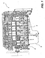
- an engine 1 comprises an engine block 2 to the bottom of which a lubricating oil sump 3 is integrally connected. Inside the sump 3 there is a suction duct 4 that is connected to the bottom of the engine block 2 of the engine 1 by means of flanges and bolts (illustrated in greater detail below).
- FIG 2 shows the sump 3 and suction duct 4 of the engine of Figure 1 in greater detail.
- the suction duct 4 comprises a first rigid duct 5 that is connected to the pump at the bottom of the engine block 2 by means of a flange and the relevant bolts (not illustrated).
- the first duct 5 is connected to a second rigid duct 6 by means of flanges 7.
- the second duct 6 has a supporting bracket 8 that is also fixed to the bottom of the engine block 2.
- the purpose of the bracket 8 is to increase the fatigue strength of the duct 6.
- the suction inlet typically incorporates a straining and filtering element to remove any solid bodies and impurities (not illustrated in the drawing).
- FIG 3 a partial and schematic illustration of the suction duct according to the present invention it is shown. For the sake of clarity same parts will have same numbers.
- the suction duct consists of a single tubular member or a pipe 4 that is flexible, and it is made of a suitable material which can be already known in the art.
- the pipe 4 has a fitting 21 for the removable coupling and complementary to the suction inlet of the oil pump, the fitting 21 being a bayonet, or screw joint type.
- the suction inlet 9 comprises a substantially cylindrical body with a suction area having a multiplicity of openings 10 in proximity to the bottom region of the sump 3.
- multiplicity of openings 10 constitute themselves an area in which any solid bodies and impurities that may have been deposited on the bottom of the sump 3 are strained or filtered to the pump.
- the pipe 4 is connected to the inlet 9 by means of the coupling 22.
- the pipe 4 is connected to the suction inlet of the pump on the engine block 2 by means of the coupling 21, and at last the sump 3 is connected to the engine block 2.
- a first advantage consists of the fact that the suction pipe comprises a single pipe 4 and there is thus no risk of leaks or intermediate breakages that could result in loss of efficiency.
- a second advantage consists of the fact that the suction pipe 4 is made of a flexible material and is thus not subject to fatigue stress that could undermine its integrity and shorten its working life.
- connection of the pipe 4 to the engine block 2 requires the use of fewer threaded connections, making connection simpler and reducing machining and assembly times.
- a further advantage consists of the fact that the assembly of the suction pipe 4 and subsequent assembly of the oil sump 3 on the engine block 2 are simplified, reducing the costs and time involved.
- Another advantage consists of the fact that, since the suction pipe 4 is more reliable, relevant repairs and engine maintenance operations can be carried out at longer intervals once the suction pipe is in use.
- Another main advantage concerns the logistics associated with the proposed solution, whereby there are fewer parts for subsequent assembly, as the sump according to this invention is supplied with the suction pipe already assembled, and less space is required at the assembly plant, since the area at the side of the line usually taken up by the suction ducts container(s) is no longer necessary.
Landscapes
- Engineering & Computer Science (AREA)
- Mechanical Engineering (AREA)
- General Engineering & Computer Science (AREA)
- Lubrication Details And Ventilation Of Internal Combustion Engines (AREA)
- Lubrication Of Internal Combustion Engines (AREA)
Description
- This invention relates to an oil suction duct for internal combustion engines and, more precisely, relates to an oil suction duct of the type designed to be installed atbottom of the oil sump of an internal combustion engine.
- In internal combustion engines, the presence of a lubricating oil pan or "sump" which is usually arranged at the bottom of the engine block, to collect and contain all of the lubricating oil, it is already known in the art. Such engines also comprise a pump driven by the engine itself that sucks the lubricating oil from the sump and delivers the same into a multiplicity of lubrication ducts where the oil is subsequently collected again into said sump.
- The lubricating oil is sucked from the sump by means of a duct, i.e. the so called suction duct, that sucks in the oil from the lowest part of the sump and delivers said oil towards the pump. Said suction duct usually has a suction inlet that is arranged in proximity to the bottom of the sump to where the oil flow is directed.
- An example of known suction duct is disclosed in the patent application
US 2002/0096221 A1 . In order to simplify construction and reduce costs, the suction duct is a rigid structure made of low-carbon metal, and is assembled and fixed to the bottom of the engine block by means of flanges before the oil sump is assembled. Although this is a low-cost solution, it still has some drawbacks. - A first drawback consists in that the suction pipe is made of metal and is therefore a rigid structure, which means it cannot be adapted to fit different types and shapes of oil sumps that may be used as the engine is updated and/or modified. This means that during the production of one of more engine lines, the type and/or shape of the suction duct must be changed each time the shape of the oil sump is changed, while maintaining the same shape or casting of the base of the engine block, dealing to an increase of production costs.
- Another drawback consists in that the suction duct is subject to strong vibrations, and being made of metal the same is also subject to mechanical fatigue, therefore the duct can easily break.
- In order to overcome the aforesaid drawback, there is provided the applying of reinforcing structural members to the suction duct so that it can be anchored at several points to the bottom of the engine block, increasing its strength. However, this solution has the drawback of requiring more work to tighten the bolts or similar devices when mounting and assembling the engine.
- Furthermore, the use of additional reinforcements on the suction pipe results in increasing production time and costs.
- Therefore, the object of the present invention is to solve the above described drawbacks by providing a suction duct for internal combustion engines that can readily be adapted for installation on different oil sump versions.
- Another object of the present invention is to provide a suction duct for internal combustion engines that is not subject to fatigue stress caused by the vibrations of the engine, thus being more reliable.
- A further object of the present invention is to provide a suction duct for internal combustion engines that is easier to assemble compared to the suction duct known in the prior art.
- The present invention thus provides to a suction duct for internal combustion engines according to
claim 1. - A detailed description of a preferred embodiment of the suction duct according to the invention will be now provided, given as a non limiting example, with reference to the annexed drawings, wherein:
-
figure 1 is a schematic view of a longitudinal section of an engine block incorporating a suction duct according to the state of the art; -
figure 2 is a schematic and partial view of an oil sump incorporating a suction duct according to the state of the art, and -
figure 3 is a schematic and partial view of an oil sump incorporating the suction duct according to this invention. - With reference now to
Figure 1 there is shown an internal combustion engine block that incorporates a suction duct of the type already known in the art. Accordingly, anengine 1 comprises anengine block 2 to the bottom of which a lubricatingoil sump 3 is integrally connected. Inside thesump 3 there is asuction duct 4 that is connected to the bottom of theengine block 2 of theengine 1 by means of flanges and bolts (illustrated in greater detail below). -
Figure 2 shows thesump 3 andsuction duct 4 of the engine ofFigure 1 in greater detail. More precisely, thesuction duct 4 comprises a firstrigid duct 5 that is connected to the pump at the bottom of theengine block 2 by means of a flange and the relevant bolts (not illustrated). Thefirst duct 5 is connected to a second rigid duct 6 by means offlanges 7. - When necessary, the second duct 6 has a supporting
bracket 8 that is also fixed to the bottom of theengine block 2. The purpose of thebracket 8 is to increase the fatigue strength of the duct 6. - At the end of the duct 6 there is a lubricating
oil suction inlet 9. The suction inlet typically incorporates a straining and filtering element to remove any solid bodies and impurities (not illustrated in the drawing). - With reference now to
figure 3 , a partial and schematic illustration of the suction duct according to the present invention it is shown. For the sake of clarity same parts will have same numbers. - According to the invention, the suction duct consists of a single tubular member or a
pipe 4 that is flexible, and it is made of a suitable material which can be already known in the art. At the end of thepipe 4 on the side which is connected to the oil pump of theengine block 2, thepipe 4 has afitting 21 for the removable coupling and complementary to the suction inlet of the oil pump, thefitting 21 being a bayonet, or screw joint type. - On the other hand, at the suction end of the
pipe 4 which corresponds to the bottom of thesump 3 there is asuction inlet 9 that is rendered integral connected to the bottom of thesump 3 by means of a welding. Thesuction inlet 9 comprises a substantially cylindrical body with a suction area having a multiplicity ofopenings 10 in proximity to the bottom region of thesump 3. - On top of said cylindrical body of the
inlet 9 there is afitting element 22 for the removable coupling of thepipe 4, thecoupling 22 being complementary and of the bayonet or screw type. - Attention must be drawn to the fact that the multiplicity of
openings 10 constitute themselves an area in which any solid bodies and impurities that may have been deposited on the bottom of thesump 3 are strained or filtered to the pump. - To assemble the suction duct, first the
pipe 4 is connected to theinlet 9 by means of thecoupling 22. Second, thepipe 4 is connected to the suction inlet of the pump on theengine block 2 by means of thecoupling 21, and at last thesump 3 is connected to theengine block 2. - The advantages of the
suction pipe 4 according to this invention will be apparent to the person skilled in the art. - A first advantage consists of the fact that the suction pipe comprises a
single pipe 4 and there is thus no risk of leaks or intermediate breakages that could result in loss of efficiency. - A second advantage consists of the fact that the
suction pipe 4 is made of a flexible material and is thus not subject to fatigue stress that could undermine its integrity and shorten its working life. - Another advantage consists of the fact that the connection of the
pipe 4 to theengine block 2 requires the use of fewer threaded connections, making connection simpler and reducing machining and assembly times. - A further advantage consists of the fact that the assembly of the
suction pipe 4 and subsequent assembly of theoil sump 3 on theengine block 2 are simplified, reducing the costs and time involved. - Another advantage consists of the fact that, since the
suction pipe 4 is more reliable, relevant repairs and engine maintenance operations can be carried out at longer intervals once the suction pipe is in use. - Another main advantage concerns the logistics associated with the proposed solution, whereby there are fewer parts for subsequent assembly, as the sump according to this invention is supplied with the suction pipe already assembled, and less space is required at the assembly plant, since the area at the side of the line usually taken up by the suction ducts container(s) is no longer necessary.
Claims (1)
- An internal combustion engine (1) comprising an engine block (2), an oil sump (3), and a suction, duct comprising:- a flexible pipe (4);- first connecting means (21) to the engine block (2) mounted at one end of said pipe (4);- second connecting means (22) mounted at the opposite end of said pipe (4); and- a suction inlet (9) between the sump (3) and said second connecting means (22),wherein:- said first connecting means comprises a coupling (21) of the threaded or bayonet type;- said second connecting means comprises a coupling (22) of the threaded or bayonet type;- said suction inclet (9) compring a cylindrical body (9) having a suction area having a multiplicity of openings (10) in proximity to the bottom of the sump (3), the top of said cylindrical body (9) comprising a complementary fitting element for the coupling with said second connecting means, said suction inlet (9) being integrally connected to the bottom of said sump (3) by welding.
Applications Claiming Priority (1)
| Application Number | Priority Date | Filing Date | Title |
|---|---|---|---|
| ITMI20050316 ITMI20050316A1 (en) | 2005-03-02 | 2005-03-02 | OIL JUICE FOR ENDOTHERMIC MOTORS |
Publications (3)
| Publication Number | Publication Date |
|---|---|
| EP1698764A2 EP1698764A2 (en) | 2006-09-06 |
| EP1698764A3 EP1698764A3 (en) | 2009-04-15 |
| EP1698764B1 true EP1698764B1 (en) | 2013-03-06 |
Family
ID=34956721
Family Applications (1)
| Application Number | Title | Priority Date | Filing Date |
|---|---|---|---|
| EP05112227A Expired - Lifetime EP1698764B1 (en) | 2005-03-02 | 2005-12-15 | Oil suction duct for internal combustion engines |
Country Status (3)
| Country | Link |
|---|---|
| EP (1) | EP1698764B1 (en) |
| ES (1) | ES2410586T3 (en) |
| IT (1) | ITMI20050316A1 (en) |
Families Citing this family (1)
| Publication number | Priority date | Publication date | Assignee | Title |
|---|---|---|---|---|
| ITUB20151211A1 (en) * | 2015-08-25 | 2015-11-25 | Mdb Srl | SELF-DIRECTIONAL OIL FISHING SYSTEM CONTAINED IN THE OIL CUP AND CONNECTED TO THE INTERNAL COMBUSTION ENGINE LUBRICATION CIRCUIT |
Citations (1)
| Publication number | Priority date | Publication date | Assignee | Title |
|---|---|---|---|---|
| DE19925354C1 (en) * | 1999-06-02 | 2000-08-03 | Daimler Chrysler Ag | Oil sump for an internal combustion motor is fitted to the crankcase in an oil sealed mounting with elastic bellows and is supported by an auxiliary carrier |
Family Cites Families (4)
| Publication number | Priority date | Publication date | Assignee | Title |
|---|---|---|---|---|
| DE3022443C2 (en) * | 1980-06-14 | 1983-04-14 | Bayerische Motoren Werke AG, 8000 München | Suction pipe for the lubricating oil circuit of an internal combustion engine |
| JP2002054418A (en) * | 2000-08-11 | 2002-02-20 | Piolax Inc | Oil strainer, and method of manufacturing same |
| JP2002106316A (en) * | 2000-09-29 | 2002-04-10 | Piolax Inc | Oil strainer |
| US6523561B2 (en) * | 2001-01-24 | 2003-02-25 | Federal-Mogul World Wide, Inc. | Snap-together filter system for transmission oil pan and method of manufacture |
-
2005
- 2005-03-02 IT ITMI20050316 patent/ITMI20050316A1/en unknown
- 2005-12-15 EP EP05112227A patent/EP1698764B1/en not_active Expired - Lifetime
- 2005-12-15 ES ES05112227T patent/ES2410586T3/en not_active Expired - Lifetime
Patent Citations (1)
| Publication number | Priority date | Publication date | Assignee | Title |
|---|---|---|---|---|
| DE19925354C1 (en) * | 1999-06-02 | 2000-08-03 | Daimler Chrysler Ag | Oil sump for an internal combustion motor is fitted to the crankcase in an oil sealed mounting with elastic bellows and is supported by an auxiliary carrier |
Also Published As
| Publication number | Publication date |
|---|---|
| ITMI20050316A1 (en) | 2006-09-03 |
| EP1698764A3 (en) | 2009-04-15 |
| ES2410586T3 (en) | 2013-07-02 |
| EP1698764A2 (en) | 2006-09-06 |
Similar Documents
| Publication | Publication Date | Title |
|---|---|---|
| US6705270B1 (en) | Oil pan module for internal combustion engines | |
| US11209124B2 (en) | Power frame and lubrication system for a reciprocating pump assembly | |
| US5190120A (en) | Flushing apparatus for vehicle oil pump pickup tube and screen | |
| JPS61106952A (en) | lightweight internal combustion engine | |
| CN100392218C (en) | Engine and method for producing the engine | |
| US20100147253A1 (en) | Oil Pan | |
| US20160130995A1 (en) | Oil pan design for drawing two sumps from a single drain plug | |
| EP2379196B1 (en) | Sealing grommet for fluid filters | |
| EP1698764A2 (en) | Oil suction duct for internal combustion engines | |
| JP2010507745A (en) | Internal combustion engine with cylinder crankcase and V-type cylinder arrangement | |
| US7204224B2 (en) | Engine block structure | |
| JP4572166B2 (en) | Oil strainer | |
| US5810571A (en) | High performance oil pump | |
| JP2005083231A (en) | Fuel filter | |
| EP1731725A2 (en) | Oil pan for automotive engines and method of making same | |
| WO1997033084A1 (en) | Crankcase for piston engines, especially v-engines | |
| JP2015194099A (en) | Internal combustion engine | |
| WO2016140672A1 (en) | Oil pan with integral lube suction and stiffening passage | |
| US7155996B2 (en) | Lubrication system for a transmission gear mechanism | |
| CN114576203B (en) | Oil pump and engine | |
| CN200958401Y (en) | Double-pump lubricating system of single-cylinder diesel engine | |
| JPH034733Y2 (en) | ||
| CN214118343U (en) | Engine cylinder block structure and engine | |
| EP3513055B1 (en) | Filter housing made of plastic and filter system | |
| CN100538025C (en) | Engine block structure |
Legal Events
| Date | Code | Title | Description |
|---|---|---|---|
| PUAI | Public reference made under article 153(3) epc to a published international application that has entered the european phase |
Free format text: ORIGINAL CODE: 0009012 |
|
| AK | Designated contracting states |
Kind code of ref document: A2 Designated state(s): AT BE BG CH CY CZ DE DK EE ES FI FR GB GR HU IE IS IT LI LT LU LV MC NL PL PT RO SE SI SK TR |
|
| AX | Request for extension of the european patent |
Extension state: AL BA HR MK YU |
|
| PUAL | Search report despatched |
Free format text: ORIGINAL CODE: 0009013 |
|
| AK | Designated contracting states |
Kind code of ref document: A3 Designated state(s): AT BE BG CH CY CZ DE DK EE ES FI FR GB GR HU IE IS IT LI LT LU LV MC NL PL PT RO SE SI SK TR |
|
| AX | Request for extension of the european patent |
Extension state: AL BA HR MK YU |
|
| 17P | Request for examination filed |
Effective date: 20091014 |
|
| 17Q | First examination report despatched |
Effective date: 20091112 |
|
| AKX | Designation fees paid |
Designated state(s): AT BE BG CH CY CZ DE DK EE ES FI FR GB GR HU IE IS IT LI LT LU LV MC NL PL PT RO SE SI SK TR |
|
| RAP1 | Party data changed (applicant data changed or rights of an application transferred) |
Owner name: NUOVA IMMOBILIARE NOVE S.P.A. |
|
| RAP1 | Party data changed (applicant data changed or rights of an application transferred) |
Owner name: FPT INDUSTRIAL S.P.A. |
|
| GRAP | Despatch of communication of intention to grant a patent |
Free format text: ORIGINAL CODE: EPIDOSNIGR1 |
|
| GRAS | Grant fee paid |
Free format text: ORIGINAL CODE: EPIDOSNIGR3 |
|
| GRAA | (expected) grant |
Free format text: ORIGINAL CODE: 0009210 |
|
| AK | Designated contracting states |
Kind code of ref document: B1 Designated state(s): AT BE BG CH CY CZ DE DK EE ES FI FR GB GR HU IE IS IT LI LT LU LV MC NL PL PT RO SE SI SK TR |
|
| REG | Reference to a national code |
Ref country code: GB Ref legal event code: FG4D |
|
| REG | Reference to a national code |
Ref country code: CH Ref legal event code: EP Ref country code: AT Ref legal event code: REF Ref document number: 599749 Country of ref document: AT Kind code of ref document: T Effective date: 20130315 |
|
| REG | Reference to a national code |
Ref country code: IE Ref legal event code: FG4D |
|
| REG | Reference to a national code |
Ref country code: DE Ref legal event code: R096 Ref document number: 602005038410 Country of ref document: DE Effective date: 20130502 |
|
| REG | Reference to a national code |
Ref country code: CH Ref legal event code: NV Representative=s name: N&G PATENT SERVICES SA, CH |
|
| REG | Reference to a national code |
Ref country code: SE Ref legal event code: TRGR |
|
| REG | Reference to a national code |
Ref country code: ES Ref legal event code: FG2A Ref document number: 2410586 Country of ref document: ES Kind code of ref document: T3 Effective date: 20130702 |
|
| REG | Reference to a national code |
Ref country code: AT Ref legal event code: MK05 Ref document number: 599749 Country of ref document: AT Kind code of ref document: T Effective date: 20130306 |
|
| PG25 | Lapsed in a contracting state [announced via postgrant information from national office to epo] |
Ref country code: BG Free format text: LAPSE BECAUSE OF FAILURE TO SUBMIT A TRANSLATION OF THE DESCRIPTION OR TO PAY THE FEE WITHIN THE PRESCRIBED TIME-LIMIT Effective date: 20130606 Ref country code: LT Free format text: LAPSE BECAUSE OF FAILURE TO SUBMIT A TRANSLATION OF THE DESCRIPTION OR TO PAY THE FEE WITHIN THE PRESCRIBED TIME-LIMIT Effective date: 20130306 Ref country code: AT Free format text: LAPSE BECAUSE OF FAILURE TO SUBMIT A TRANSLATION OF THE DESCRIPTION OR TO PAY THE FEE WITHIN THE PRESCRIBED TIME-LIMIT Effective date: 20130306 |
|
| REG | Reference to a national code |
Ref country code: NL Ref legal event code: VDEP Effective date: 20130306 |
|
| REG | Reference to a national code |
Ref country code: LT Ref legal event code: MG4D |
|
| PG25 | Lapsed in a contracting state [announced via postgrant information from national office to epo] |
Ref country code: LV Free format text: LAPSE BECAUSE OF FAILURE TO SUBMIT A TRANSLATION OF THE DESCRIPTION OR TO PAY THE FEE WITHIN THE PRESCRIBED TIME-LIMIT Effective date: 20130306 Ref country code: SI Free format text: LAPSE BECAUSE OF FAILURE TO SUBMIT A TRANSLATION OF THE DESCRIPTION OR TO PAY THE FEE WITHIN THE PRESCRIBED TIME-LIMIT Effective date: 20130306 Ref country code: GR Free format text: LAPSE BECAUSE OF FAILURE TO SUBMIT A TRANSLATION OF THE DESCRIPTION OR TO PAY THE FEE WITHIN THE PRESCRIBED TIME-LIMIT Effective date: 20130607 Ref country code: FI Free format text: LAPSE BECAUSE OF FAILURE TO SUBMIT A TRANSLATION OF THE DESCRIPTION OR TO PAY THE FEE WITHIN THE PRESCRIBED TIME-LIMIT Effective date: 20130306 |
|
| PG25 | Lapsed in a contracting state [announced via postgrant information from national office to epo] |
Ref country code: BE Free format text: LAPSE BECAUSE OF FAILURE TO SUBMIT A TRANSLATION OF THE DESCRIPTION OR TO PAY THE FEE WITHIN THE PRESCRIBED TIME-LIMIT Effective date: 20130306 |
|
| PG25 | Lapsed in a contracting state [announced via postgrant information from national office to epo] |
Ref country code: IS Free format text: LAPSE BECAUSE OF FAILURE TO SUBMIT A TRANSLATION OF THE DESCRIPTION OR TO PAY THE FEE WITHIN THE PRESCRIBED TIME-LIMIT Effective date: 20130706 Ref country code: SK Free format text: LAPSE BECAUSE OF FAILURE TO SUBMIT A TRANSLATION OF THE DESCRIPTION OR TO PAY THE FEE WITHIN THE PRESCRIBED TIME-LIMIT Effective date: 20130306 Ref country code: CZ Free format text: LAPSE BECAUSE OF FAILURE TO SUBMIT A TRANSLATION OF THE DESCRIPTION OR TO PAY THE FEE WITHIN THE PRESCRIBED TIME-LIMIT Effective date: 20130306 Ref country code: NL Free format text: LAPSE BECAUSE OF FAILURE TO SUBMIT A TRANSLATION OF THE DESCRIPTION OR TO PAY THE FEE WITHIN THE PRESCRIBED TIME-LIMIT Effective date: 20130306 Ref country code: RO Free format text: LAPSE BECAUSE OF FAILURE TO SUBMIT A TRANSLATION OF THE DESCRIPTION OR TO PAY THE FEE WITHIN THE PRESCRIBED TIME-LIMIT Effective date: 20130306 Ref country code: EE Free format text: LAPSE BECAUSE OF FAILURE TO SUBMIT A TRANSLATION OF THE DESCRIPTION OR TO PAY THE FEE WITHIN THE PRESCRIBED TIME-LIMIT Effective date: 20130306 Ref country code: PT Free format text: LAPSE BECAUSE OF FAILURE TO SUBMIT A TRANSLATION OF THE DESCRIPTION OR TO PAY THE FEE WITHIN THE PRESCRIBED TIME-LIMIT Effective date: 20130708 |
|
| PG25 | Lapsed in a contracting state [announced via postgrant information from national office to epo] |
Ref country code: CY Free format text: LAPSE BECAUSE OF FAILURE TO SUBMIT A TRANSLATION OF THE DESCRIPTION OR TO PAY THE FEE WITHIN THE PRESCRIBED TIME-LIMIT Effective date: 20130306 Ref country code: PL Free format text: LAPSE BECAUSE OF FAILURE TO SUBMIT A TRANSLATION OF THE DESCRIPTION OR TO PAY THE FEE WITHIN THE PRESCRIBED TIME-LIMIT Effective date: 20130306 |
|
| PLBE | No opposition filed within time limit |
Free format text: ORIGINAL CODE: 0009261 |
|
| STAA | Information on the status of an ep patent application or granted ep patent |
Free format text: STATUS: NO OPPOSITION FILED WITHIN TIME LIMIT |
|
| PG25 | Lapsed in a contracting state [announced via postgrant information from national office to epo] |
Ref country code: DK Free format text: LAPSE BECAUSE OF FAILURE TO SUBMIT A TRANSLATION OF THE DESCRIPTION OR TO PAY THE FEE WITHIN THE PRESCRIBED TIME-LIMIT Effective date: 20130306 |
|
| 26N | No opposition filed |
Effective date: 20131209 |
|
| REG | Reference to a national code |
Ref country code: DE Ref legal event code: R097 Ref document number: 602005038410 Country of ref document: DE Effective date: 20131209 |
|
| PG25 | Lapsed in a contracting state [announced via postgrant information from national office to epo] |
Ref country code: MC Free format text: LAPSE BECAUSE OF FAILURE TO SUBMIT A TRANSLATION OF THE DESCRIPTION OR TO PAY THE FEE WITHIN THE PRESCRIBED TIME-LIMIT Effective date: 20130306 Ref country code: LU Free format text: LAPSE BECAUSE OF FAILURE TO SUBMIT A TRANSLATION OF THE DESCRIPTION OR TO PAY THE FEE WITHIN THE PRESCRIBED TIME-LIMIT Effective date: 20131215 |
|
| REG | Reference to a national code |
Ref country code: IE Ref legal event code: MM4A |
|
| PG25 | Lapsed in a contracting state [announced via postgrant information from national office to epo] |
Ref country code: IE Free format text: LAPSE BECAUSE OF NON-PAYMENT OF DUE FEES Effective date: 20131215 |
|
| PG25 | Lapsed in a contracting state [announced via postgrant information from national office to epo] |
Ref country code: TR Free format text: LAPSE BECAUSE OF FAILURE TO SUBMIT A TRANSLATION OF THE DESCRIPTION OR TO PAY THE FEE WITHIN THE PRESCRIBED TIME-LIMIT Effective date: 20130306 |
|
| PG25 | Lapsed in a contracting state [announced via postgrant information from national office to epo] |
Ref country code: HU Free format text: LAPSE BECAUSE OF FAILURE TO SUBMIT A TRANSLATION OF THE DESCRIPTION OR TO PAY THE FEE WITHIN THE PRESCRIBED TIME-LIMIT; INVALID AB INITIO Effective date: 20051215 |
|
| REG | Reference to a national code |
Ref country code: FR Ref legal event code: PLFP Year of fee payment: 11 |
|
| REG | Reference to a national code |
Ref country code: FR Ref legal event code: PLFP Year of fee payment: 12 |
|
| REG | Reference to a national code |
Ref country code: FR Ref legal event code: PLFP Year of fee payment: 13 |
|
| PGFP | Annual fee paid to national office [announced via postgrant information from national office to epo] |
Ref country code: GB Payment date: 20181221 Year of fee payment: 14 |
|
| PGFP | Annual fee paid to national office [announced via postgrant information from national office to epo] |
Ref country code: SE Payment date: 20181228 Year of fee payment: 14 |
|
| REG | Reference to a national code |
Ref country code: SE Ref legal event code: EUG |
|
| REG | Reference to a national code |
Ref country code: CH Ref legal event code: PL |
|
| GBPC | Gb: european patent ceased through non-payment of renewal fee |
Effective date: 20191215 |
|
| PG25 | Lapsed in a contracting state [announced via postgrant information from national office to epo] |
Ref country code: GB Free format text: LAPSE BECAUSE OF NON-PAYMENT OF DUE FEES Effective date: 20191215 Ref country code: SE Free format text: LAPSE BECAUSE OF NON-PAYMENT OF DUE FEES Effective date: 20191216 |
|
| PG25 | Lapsed in a contracting state [announced via postgrant information from national office to epo] |
Ref country code: CH Free format text: LAPSE BECAUSE OF NON-PAYMENT OF DUE FEES Effective date: 20191231 Ref country code: LI Free format text: LAPSE BECAUSE OF NON-PAYMENT OF DUE FEES Effective date: 20191231 |
|
| REG | Reference to a national code |
Ref country code: ES Ref legal event code: FD2A Effective date: 20210526 |
|
| PG25 | Lapsed in a contracting state [announced via postgrant information from national office to epo] |
Ref country code: ES Free format text: LAPSE BECAUSE OF NON-PAYMENT OF DUE FEES Effective date: 20191216 |
|
| P01 | Opt-out of the competence of the unified patent court (upc) registered |
Effective date: 20230519 |
|
| PGFP | Annual fee paid to national office [announced via postgrant information from national office to epo] |
Ref country code: IT Payment date: 20231201 Year of fee payment: 19 Ref country code: FR Payment date: 20231226 Year of fee payment: 19 |
|
| PGFP | Annual fee paid to national office [announced via postgrant information from national office to epo] |
Ref country code: DE Payment date: 20231227 Year of fee payment: 19 |
|
| REG | Reference to a national code |
Ref country code: DE Ref legal event code: R119 Ref document number: 602005038410 Country of ref document: DE |
|
| PG25 | Lapsed in a contracting state [announced via postgrant information from national office to epo] |
Ref country code: DE Free format text: LAPSE BECAUSE OF NON-PAYMENT OF DUE FEES Effective date: 20250701 |
|
| PG25 | Lapsed in a contracting state [announced via postgrant information from national office to epo] |
Ref country code: IT Free format text: LAPSE BECAUSE OF NON-PAYMENT OF DUE FEES Effective date: 20241215 |
|
| PG25 | Lapsed in a contracting state [announced via postgrant information from national office to epo] |
Ref country code: FR Free format text: LAPSE BECAUSE OF NON-PAYMENT OF DUE FEES Effective date: 20241231 |