EP1698546A2 - Wiring connection structure for bicycle - Google Patents
Wiring connection structure for bicycle Download PDFInfo
- Publication number
- EP1698546A2 EP1698546A2 EP06110458A EP06110458A EP1698546A2 EP 1698546 A2 EP1698546 A2 EP 1698546A2 EP 06110458 A EP06110458 A EP 06110458A EP 06110458 A EP06110458 A EP 06110458A EP 1698546 A2 EP1698546 A2 EP 1698546A2
- Authority
- EP
- European Patent Office
- Prior art keywords
- wiring
- connection
- electrical
- connection terminal
- cover member
- Prior art date
- Legal status (The legal status is an assumption and is not a legal conclusion. Google has not performed a legal analysis and makes no representation as to the accuracy of the status listed.)
- Withdrawn
Links
Images


Classifications
-
- H—ELECTRICITY
- H02—GENERATION; CONVERSION OR DISTRIBUTION OF ELECTRIC POWER
- H02G—INSTALLATION OF ELECTRIC CABLES OR LINES, OR OF COMBINED OPTICAL AND ELECTRIC CABLES OR LINES
- H02G15/00—Cable fittings
- H02G15/08—Cable junctions
- H02G15/18—Cable junctions protected by sleeves, e.g. for communication cable
- H02G15/1806—Heat shrinkable sleeves
-
- B—PERFORMING OPERATIONS; TRANSPORTING
- B62—LAND VEHICLES FOR TRAVELLING OTHERWISE THAN ON RAILS
- B62J—CYCLE SADDLES OR SEATS; AUXILIARY DEVICES OR ACCESSORIES SPECIALLY ADAPTED TO CYCLES AND NOT OTHERWISE PROVIDED FOR, e.g. ARTICLE CARRIERS OR CYCLE PROTECTORS
- B62J11/00—Supporting arrangements specially adapted for fastening specific devices to cycles, e.g. supports for attaching maps
- B62J11/10—Supporting arrangements specially adapted for fastening specific devices to cycles, e.g. supports for attaching maps for mechanical cables, hoses, pipes or electric wires, e.g. cable guides
- B62J11/19—Supporting arrangements specially adapted for fastening specific devices to cycles, e.g. supports for attaching maps for mechanical cables, hoses, pipes or electric wires, e.g. cable guides specially adapted for electric wires
-
- B—PERFORMING OPERATIONS; TRANSPORTING
- B62—LAND VEHICLES FOR TRAVELLING OTHERWISE THAN ON RAILS
- B62K—CYCLES; CYCLE FRAMES; CYCLE STEERING DEVICES; RIDER-OPERATED TERMINAL CONTROLS SPECIALLY ADAPTED FOR CYCLES; CYCLE AXLE SUSPENSIONS; CYCLE SIDECARS, FORECARS, OR THE LIKE
- B62K23/00—Rider-operated controls specially adapted for cycles, i.e. means for initiating control operations, e.g. levers, grips
- B62K23/02—Rider-operated controls specially adapted for cycles, i.e. means for initiating control operations, e.g. levers, grips hand actuated
-
- B—PERFORMING OPERATIONS; TRANSPORTING
- B62—LAND VEHICLES FOR TRAVELLING OTHERWISE THAN ON RAILS
- B62M—RIDER PROPULSION OF WHEELED VEHICLES OR SLEDGES; POWERED PROPULSION OF SLEDGES OR SINGLE-TRACK CYCLES; TRANSMISSIONS SPECIALLY ADAPTED FOR SUCH VEHICLES
- B62M25/00—Actuators for gearing speed-change mechanisms specially adapted for cycles
- B62M25/08—Actuators for gearing speed-change mechanisms specially adapted for cycles with electrical or fluid transmitting systems
-
- H—ELECTRICITY
- H01—ELECTRIC ELEMENTS
- H01R—ELECTRICALLY-CONDUCTIVE CONNECTIONS; STRUCTURAL ASSOCIATIONS OF A PLURALITY OF MUTUALLY-INSULATED ELECTRICAL CONNECTING ELEMENTS; COUPLING DEVICES; CURRENT COLLECTORS
- H01R4/00—Electrically-conductive connections between two or more conductive members in direct contact, i.e. touching one another; Means for effecting or maintaining such contact; Electrically-conductive connections having two or more spaced connecting locations for conductors and using contact members penetrating insulation
- H01R4/10—Electrically-conductive connections between two or more conductive members in direct contact, i.e. touching one another; Means for effecting or maintaining such contact; Electrically-conductive connections having two or more spaced connecting locations for conductors and using contact members penetrating insulation effected solely by twisting, wrapping, bending, crimping, or other permanent deformation
- H01R4/18—Electrically-conductive connections between two or more conductive members in direct contact, i.e. touching one another; Means for effecting or maintaining such contact; Electrically-conductive connections having two or more spaced connecting locations for conductors and using contact members penetrating insulation effected solely by twisting, wrapping, bending, crimping, or other permanent deformation by crimping
- H01R4/183—Electrically-conductive connections between two or more conductive members in direct contact, i.e. touching one another; Means for effecting or maintaining such contact; Electrically-conductive connections having two or more spaced connecting locations for conductors and using contact members penetrating insulation effected solely by twisting, wrapping, bending, crimping, or other permanent deformation by crimping for cylindrical elongated bodies, e.g. cables having circular cross-section
- H01R4/184—Electrically-conductive connections between two or more conductive members in direct contact, i.e. touching one another; Means for effecting or maintaining such contact; Electrically-conductive connections having two or more spaced connecting locations for conductors and using contact members penetrating insulation effected solely by twisting, wrapping, bending, crimping, or other permanent deformation by crimping for cylindrical elongated bodies, e.g. cables having circular cross-section comprising a U-shaped wire-receiving portion
- H01R4/185—Electrically-conductive connections between two or more conductive members in direct contact, i.e. touching one another; Means for effecting or maintaining such contact; Electrically-conductive connections having two or more spaced connecting locations for conductors and using contact members penetrating insulation effected solely by twisting, wrapping, bending, crimping, or other permanent deformation by crimping for cylindrical elongated bodies, e.g. cables having circular cross-section comprising a U-shaped wire-receiving portion combined with a U-shaped insulation-receiving portion
-
- H—ELECTRICITY
- H01—ELECTRIC ELEMENTS
- H01R—ELECTRICALLY-CONDUCTIVE CONNECTIONS; STRUCTURAL ASSOCIATIONS OF A PLURALITY OF MUTUALLY-INSULATED ELECTRICAL CONNECTING ELEMENTS; COUPLING DEVICES; CURRENT COLLECTORS
- H01R13/00—Details of coupling devices of the kinds covered by groups H01R12/70 or H01R24/00 - H01R33/00
- H01R13/02—Contact members
- H01R13/10—Sockets for co-operation with pins or blades
- H01R13/11—Resilient sockets
- H01R13/113—Resilient sockets co-operating with pins or blades having a rectangular transverse section
-
- Y—GENERAL TAGGING OF NEW TECHNOLOGICAL DEVELOPMENTS; GENERAL TAGGING OF CROSS-SECTIONAL TECHNOLOGIES SPANNING OVER SEVERAL SECTIONS OF THE IPC; TECHNICAL SUBJECTS COVERED BY FORMER USPC CROSS-REFERENCE ART COLLECTIONS [XRACs] AND DIGESTS
- Y10—TECHNICAL SUBJECTS COVERED BY FORMER USPC
- Y10S—TECHNICAL SUBJECTS COVERED BY FORMER USPC CROSS-REFERENCE ART COLLECTIONS [XRACs] AND DIGESTS
- Y10S439/00—Electrical connectors
- Y10S439/932—Heat shrink material
Definitions
- the present invention relates to a wiring connection structure, and more particularly to a wiring connection structure for a bicycle for electrically connecting a first electrical wiring connected to a first electrical component mounted to a frame of the bicycle including a handle and a second electrical wiring mounted to a second electrical component.
- Recent bicycles have incorporated many electrical components besides a lamp.
- electrical components such as an electric drive force assist device for assisting a drive force from pedals or an electric shift device for electrically or pneumatically performing ashiftoperation have been widely used.
- Many electrical components for controlling or operating these electrical components have been also used.
- a conventional wiring connection structure for connecting these electrical components terminals attached to electric wirings are connected to a connection terminal mount provided in an electrical component by screws or male and female fitting (for example, see Japanese Patent Laid-Open No. 2004-159490 (FIGS. 5 and 7)).
- the electrical wiring is placed in an exposed manner along a frame, and connects, for example, a shift switch provided in a handle and a display portion, or the displayportion anda control portionprovided in the middle of the frame.
- the electrical wiring is connected to the connection terminal mount provided in the electrical component, and thus it is difficult to make the structure waterproof.
- the terminal mount may be exposed to the outside to cause poor insulation or falling off of the wiring resulting from corrosion by moisture.
- the electrical wiring is placed in the exposed manner along the frame, and thus the electrical wiring may be caught by an obstacle to be cut or damaged.
- the electrical wiring is inserted into the frame.
- An object of the present invention is to provide a wiring connection structure for electrically connecting two electrical components that is easily made waterproof and can prevent poor insulation or falling off of a wiring.
- Another object of the present invention is to provide a wiring connection structure for electrically connecting two electrical components that facilitates insertion of a wiring into a frame.
- a wiring connection structure for a bicycle according to a first object of the invention is a wiring connection structure for a bicycle for electrically connecting a first electrical wiring connected to a first electrical component mounted to a frame of the bicycle including a handle and a second electrical wiring connected to a second electrical component, including: a first connection terminal; a second connection terminal; and a tubular cover member.
- the first connection terminal is a terminal electrically connectable to the first electrical wiring.
- the second connection terminal is a terminal electrically connectable to the second electrical wiring and the first connection terminal.
- the cover member is a heat-shrinkable synthetic resin member covering at least both the connection terminals.
- the cover member covers and heats at least both the connection terminals, preferably both the connection terminals and part of the electrical wirings connected thereto.
- the cover member shrinks along the shape of both the connection terminals connected, covers both the connection terminals, and comes into contact with both the connection terminals and both the electrical wirings. This prevents both the connection terminals from being detached, and prevents a liquid from entering the connection terminals, thereby achieving waterproof effect.
- both the connection terminals are insulated and become nonconductive even if the connection terminals come into contact wi th a conductive member .
- the heat-shrinkable synthetic resin cover member covers at least both the connection terminals, and thus both the connection terminals connected are covered with the cover member and heated to allow the cover member to shrink along the shape of both the connection terminals. This facilitates providing a waterproof structure and prevents poor insulation or falling off of the wirings.
- the first and second electrical wirings are previously connected to the first and second electrical components, and then the first and second electrical wirings are drawn out of the frame from positions to which the electrical components are mounted through the inside of the frame, the two electrical wirings drawn out are connected using the first and second connection terminals and then accommodated in the frame, thereby facilitating the insertion of the electrical wirings into the frame.
- both the connection terminals are covered with the heat-shrinking synthetic resin cover member, thereby maintaining insulation and waterproof properties and preventing the connection terminals or the wirings from being detached.
- the first connection terminal includes a first crimp portion to which the first electrical wiring can be crimped, and a first connection portion placed next to the first crimp portion and connectable to the second connection terminal by male and female fitting
- the second connection terminal includes a second crimp portion to which the second electrical wiring can be crimped, and a second connection portion placed next to the second crimp portion and connectable to the first connection terminal by male and female fitting
- the cover member has sufficient length to cover at least the first and second crimp portions and the first and second connection portions with both the connection terminals being connected.
- the two connection terminals constituted by crimp terminals to which the electrical wirings are crimped are reliably covered with the cover member, and part of the electrical wirings are also covered with the cover member to further improve the waterproof property.
- the first and second connection terminals and the cover member can be accommodated in the frame.
- all components can be accommodated in the frame, and thus both the electrical wirings can be inserted into the frame from the positions to which the electrical components are mounted, drawn out of the frame and connected using both the connection terminals, and then accommodated in the frame, thereby facilitating the insertion of the electrical wirings into the frame.
- the first electrical component is a shift operation portion having a shift operation switch mounted to the handle
- the second electrical component is a shift control portion that outputs a shift signal to a shift device by an on/off operation of the switch mounted to the handle
- the first and second connection terminals and the cover member can be accommodated in the handle.
- the shift operation portion as the first electrical component and the shift control portion as the second electrical component can be easily connected in the handle.
- the cover member is made of transparent polyolefin resin.
- the polyolefin resin that is relatively low in cost and versatile is used to cover both the connection terminals at low costs.
- the heat-shrinkable synthetic resin cover member covers at least both the connection terminals, and thus both the connection terminals connected are covered with the cover member and heated to allow the cover member to shrink along the shape of both the connection terminals. This facilitates providing a waterproof structure and prevents poor insulation or falling off of the wirings.
- the first and second electrical wirings are previously connected to the first and second electrical components, and then drawn out of the frame from the positions to which the electrical components are mounted through the inside of the frame, the two electrical wirings drawn out are connected using the first and second connection terminals and then accommodated in the frame, thereby facilitating the insertion of the electrical wirings into the frame.
- both the connection terminals are covered with the heat-shrinking synthetic resin cover member, thereby maintaining insulation and waterproof properties and preventing the connection terminals or the wirings from being detached.
- a bicycle adopting an embodiment of the present invention is a mountain bike with front and rear suspensions, and includes a frame 1 having a frame body 2 with a rear suspension 13r, a front fork 3 with a front suspension 13f, and a handle portion 4 (an example of a handle), a drive portion 5 including front and rear shift devices 8 and 9, a front wheel 6 mounted to the front fork 3, a rear wheel 7 to which a hub dynamo 10 is mounted, and a control device 11 (FIG. 3) for controllingportions including the front and rear shift devices 8 and 9.
- the frame body 2 of the frame 1 is created by welding an odd-form rectangular pipe. Portions including a saddle 18 and the drive portion 5 are mounted to the frame body 2.
- the front fork 3 is oscillably mounted around a tilted shaft in front of the frame body 2.
- the handle portion 4 includes a handle stem 12 secured to an upper portion of the front fork 3, and a handlebar 15 secured to the handle stem 12.
- Brake levers 16 and grips 17 are mounted to opposite ends of the handlebar 15.
- a switch unit (an example of a first electrical component) 23a having rear shift switches 20a and 20b for a manual shift operation of the rear shift device 9 and an operation switch 21a for switching an operation mode between an automatic shift mode and a manual shift mode, and a switch unit (an example of the first electrical component) 23b having front shift switches 20c and 20d for a manual shift operation of the front shift device 8 and an operation switch 21b for manually switching the degree of stiffness of the suspensions 13f and 13r are mounted to the inside of portions to which the brake levers 16 are mounted.
- the shift switch 20a is a switch for shifting down a rear derailleur 26r described later stepwise in a manual shift mode
- the shift switch 20b is a switch for shifting up the rear derailleur 26r stepwise
- the shift switch 20c is a switch for shifting down a front derailleur 26f described later stepwise in the manual shift mode
- the shift switch 20d is a switch for shifting up the front derailleur 26f stepwise.
- the drive portion 5 has a crank 27 provided in a lower portion (a hanger portion) of the frame body 2, and the externally mounted front and rear shift devices 8 and 9.
- the front shift device 8 has three sprockets F1 to F3 mounted to the crank 27 and the front derailleur 26f mounted to the frame body 2.
- the rear shift device 9 has a multistage gear 25 having, for example, eight sprockets R1 to R8, and the rear derailleur 26r mounted to a rear portion of the frame body 2.
- the crank 27 has a gear crank 27a to which the three sprockets F1 to F3 are mounted and a left crank 27b.
- the drive portion 5 has a chain 29 wound around any of the sprockets F1 to F3 and R1 to R8 of the gear crank 27a and the multistage gear 25.
- the number of teeth is successively increased from the sprocket F1 having the smallest number of teeth, and the sprocket F3 having the largest number of teeth is placed on the outermost side.
- the number of teeth is successively decreased from the sprocket R1 having the largest number of teeth, and the sprocket R8 having the smallest number of teeth is placed on the outermost side.
- the number of sprockets R1 to R8 are not precisely shown for simplicity of the drawing.
- a rotation detector (not shown) for detecting a rotation of the crank 27 is mounted to the center of rotation on the side of the left crank 27b.
- the rotation detector has a lead switch 24 (FIG. 3) and a magnet (not shown) spaced in a rotation direction of the crank 27 on the side of the center of rotation of the lead switch 24, and four pulses are output from the lead switch 24 for each rotation of the crank 27.
- the rotation detector is provided so that a shift operation is performed only when the crank 27 rotates because the externally mounted shift device cannot be shifted without the rotation of the crank 27.
- the hub dynamo 10 of the rear wheel 7 is a hub to which a brake disk of a disc brake and a freewheel to which the multistage gear 25 is mounted can be mounted, and has an AC generator 19 (FIG. 3) therein that generates electric power by rotation of the rear wheel 7.
- the control device 11 controls the shift devices 8 and 9 and the suspensions 13f and 13r according to the operations of the shift switches 20a to 20d and the operation switches 21a and 21b, and automatically controls them according to the speed.
- the control device 11 (an example of a second electrical component) has three control units: first, second, and third control units 30 to 32.
- the first control unit 30 is connected to the AC generator 19.
- the first control unit 30 is driven by electric power generated by the AC generator 19, and controls the front derailleur 26f, the rear derailleur 26r, and the rear suspension 13r with the supplied electric power.
- the first control unit 30 is connected to the second control unit 31, and supplies a control signal on the electric power to the second control unit 31 or the third control unit 32. Specifically, the supplied electric power is turned on/off according to the control signal to output the control signal on the electric power.
- the second control unit 31 controls the front suspension 13f according to a control signal sent from the first control unit 30, and mediates operation information of the switches 20a to 20d, 21a, and 21b to the first control unit 30.
- the third control unit 32 is detachably mounted to the second control unit 31.
- the third control unit 32 has a liquid crystal display portion 56 that can display traveling information, and controls the display on the liquid crystal display portion 56 according to the control signal output from the first control unit 30.
- the liquid crystal display portion 56 displays traveling information such as a vehicle speed, a traveling distance, or a shift position.
- the first control unit 30 is mounted to, for example, the hanger portion in the lower portion of the frame body 2, and provided adjacent to the rotation detector and the front derailleur 26f.
- the first control unit 30 controls the shift devices 8 and 9 and the rear suspension 13r according to the operation mode.
- the first control unit 30 controls the shift of the shift devices 8 and 9 according to the speed and the degree of stiffness of the rear suspension 13r between high and low according to the speed.
- the first control unit 30 controls the shift devices 8 and 9 and the rear suspension 13r according to operations of the shift switches 20a to 20d and the operation switch 21b.
- a speed signal is output to the second control unit 31 and the third control unit 32 as a control signal.
- the first control unit 30 has a first control portion 35 constituted by a microcomputer including a CPU, a memory, an I/O interface, or the like.
- a waveform shaping circuit 36 for generating a speed signal according to a pulse output from the AC generator 19, a charge control circuit 33, a first power storage element 38a, a lead switch 24 of the rotation detector, a power supply communication circuit 34, and a power on/off switch 28 are connected to the first control portion 35.
- a motor driver (FMD) 39f of the front derailleur 26f, amotordriver (RMD) 39r of therearderailleur26r, anoperation position sensor (FLS) 41f of the front derailleur 26f, an operation position sensor (RLS) 41r of the rear derailleur 26r, and a motor driver (RSD) 43r of the rear suspension 13r are also connected to the first control portion 35.
- Traveling data such as various traveling information and control data required for control are stored in the memory in the first control portion 35.
- Electric power from a second power storage element 38b connected to the first power storage element 38a via a diode 42 is supplied to the first control portion 35.
- the diode 42 is provided to pass an electric current in one direction only from the first power storage element 38a to the second power storage element 38b. This prevents backflow from the second power storage element 38b to the first power storage element 38a .
- the first power storage element 38a is mainly used as power supply for electrical equipment having high power consumption and large electric capacity such as the motor drivers 39f, 39r, 43f, and 43r, or the suspensions 13f and 13r or the deraille 26f and 26r having motors driven by the motor drivers 39f, 39r, 43f, and 43r.
- the first power storage element 38a is also used as power supply for a second control portion 45 described later.
- the second power storage element 38b is used as power supply for electrical equipment having low power consumption and small electric capacity such as the first control portion 35, a third control portion 55 described later, or the liquid crystal display portion 56.
- the first and second power storage elements 38a and 38b are constituted by large capacity capacitors such as electric double layer capacitors, and store DC power output from the AC generator 19 and rectified by the charge control circuit 33 .
- the power storage elements 38a and 38b may be constituted by secondary batteries such as nickel-cadmium batteries, lithium ion batteries, or nickel hydrogen batteries, instead of the capacitors.
- the charge control circuit 33 includes a rectifier circuit 37 that rectifies the electric power output from the AC generator 19 and generates the DC power, and a charge on/off switch 40 for turning on/off the electric power output from the rectifier circuit 37 according to a voltage signal from the first control portion 35.
- the charge on/off switch 40 is for preventing the first power storage element 38a from storing electric power of an excessive voltage.
- the voltage of the first power storage element 38a is monitored by the first control portion 35, and the first control portion 35 outputs a voltage signal for turning off the charge on/off switch 40 when the monitored voltage reaches a predetermined voltage (for example, 7 volt) or more to open the charge on/off switch 40.
- the first control portion 35 outputs a voltage signal for turning on the charge on/off switch 40 when the monitored voltage reaches a predetermined voltage (for example, 5.5 volt) or less to close the charge on/off switch 40.
- the power supply communication circuit 34 is also connected to the second power storage element 38b.
- the power supply communication circuit 34 turns on/off electric power supplied from the second power storage element 38b according to a control signal depending on information from the first control portion 35 on a speed, a distance, a shift stage, an automatic or manual operation, or the degree of stiffness of the suspension to supply electric power including the control signal to the second control unit 31.
- the power on/off switch 28 is also connected to the first power storage element 38a.
- the power on/off switch 28 is provided to turn on/off the electric power supplied from the first power storage element 38a to the motor driver 43f of the front suspension 13f and the second control unit 31.
- the power on/off switch 28 is turned off by a signal from the first control portion 35 when control of the degree of stiffness of the front and rear suspensions 13f and 13r is finished, and turned on when the control is started. This prevents unnecessary consumption of electric power by the first power storage element 38a.
- the motor drivers 39f, 39r, 43f, and 43r output drive signals for driving the motors 44f and 44r provided in the derailleurs 26f and 26r and the motors (not shown) provided in the suspensions 13f and 13r to the motors according to the control signal.
- the second control unit 31 is mounted by a bracket 49 securable to the handlebar 15 of the handle portion 4.
- the second control unit 31 has the second control portion 45 constituted by the microcomputer as shown in FIG. 4.
- a first receiving circuit 46 and the motor driver (FSD) 43f of the front suspension 13f are connected to the second control portion 45.
- the first receiving circuit 46 is connected to the power supply communication circuit 34 of the first control unit 30, and extracts the control signal included in the electric power and output the signal to the second control portion 45 .
- the power supply communication circuit 34 is also connected to the third power storage element 38c.
- the third power storage element 38c uses a relatively small capacity capacitor such as an electrolytic capacitor, and is provided to smooth the electric power turned on/off according to the control signal.
- a buffer amplifier 48 is connected to the third power storage element 38c.
- the buffer amplifier 48 is an amplifier that can maintain an input/output voltage at a constant level, and is provided to stabilize an analog voltage signal from the shift switches 20a and 20b and the operation switches 21a and 21b.
- the second control unit 31 is operated by the electric power from the first power storage element 38a, and controls the front suspension 13f according to the operation mode based on the control signal on the electric power of the second power storage element 38b. Specifically, in the automatic mode, the second control unit 31 switches the degree of stiffness of the front suspension 13f according to the speed, and in the manual shift mode, the second control unit 31 switches the degree of stiffness of the front suspension 13f according to the operation of the operation switch 21b. As described above, the second control portion 45 is operated by the power on/off switch 28 only when the suspension is controlled.
- the third control unit 32 is a so-called cycle computer, and is detachably mounted to the second control unit 31.
- a battery 59 such as a button battery is mounted to the third control unit 32 so that electric power can be also supplied from the battery 59. This allows the third control unit 32 to be operated even if the third control unit 32 is detached from the second control unit 31.
- various initial setting such as setting of a wheel diameter can be performed and various data such as a traveling distance or a traveling time can be stored.
- the third control unit 32 has the third control portion 55 constituted by the microcomputer.
- the liquid crystal display portion 56, a back light 58, the battery 59, a second receiving circuit 64, and a fourth power storage element 38d are connected to the third control portion 55.
- the liquid crystal display portion 56 can display various traveling information such as a speed, cadence, a traveling distance, a shift position, or the state of suspensions, and is illuminated by the back light 58.
- An electric power stabilizing circuit 57 stabilizes electric power including anon/off signal by, for example, smoothing even if the electric power is turned on/off to supply the control signal. This prevents flickering of the back light 58 even if the on/off control signal is on the electric power.
- the second receiving circuit 64 is connected in parallel with the first receiving circuit 46, and extract a control signal included in the electric power from the second power storage element 38b and outputs the signal to the third control portion 55.
- the fourth power storage element 38d is constituted by, for example, an electrolytic capacitor, and provided to store the electric power supplied from the second power storage element 38b to reduce influence of the on/off control signal.
- the fourth power storage element 38d is connected in parallel with the second receiving circuit 64 and connected to the third control portion 55 and the electric power stabilizing circuit 57.
- the AC generator 19 of the hub dynamo 10 generates electric power when the bicycle travels, the electric power is fed to the first control unit 30 and stored in the first and second power storage elements 38a and 38b.
- the AC generator 19 is provided in the rear wheel 7, and thus the first and second power storage elements 38a and 38b can be charged by rotating pedals with a stand being raised, even if the amount of charge is insufficient.
- rotating the pedals for adjusting the shift device allows easy charging, and facilitates an operation such as setting of the liquid crystal display portion 56 even if the amount of charge is insufficient.
- the first control unit 30 is provided in the hanger portion, and is close to the AC generator 19. Thus, a short power supply cable may be used to increase efficiency of transmission of signals and electric power supply.
- a signal of a different analog voltage is output to the first control portion 35 via the buffer amplifier 48, and the first control portion 35 generates signals for controlling the deraille 26f and 26r, signals for controlling the suspensions 13f and 13, or a signal for changing the mode.
- the signal for controlling the front suspension 13f is output to the power supply communication circuit 34, turns on/off the electric power like the speed signal, and is output to the second control portion 45 to control the front suspension 13f in the second control portion 45.
- a 3-wire first electrical wiring 50 is connected to the switch unit 23a.
- the first electrical wiring 50 is connected to the shift switches 20a and 20b and the operation switch 21a in the switch unit 23a.
- a first cord 50a of the first electrical wiring 50 is connected to one end of the operation switch 21a
- a second cord 50b is connected to one ends of the shift switches 20a and 20b via resistances with different values.
- a third cord 50c is a common wire, and connected to the other ends of the operation switch 21a and the shift switches 20a and 20b.
- Such connection causes an analog signal according to the on/off operation of the operation switch 21a is output from the first cord 50a to the buffer amplifier 48, and a signal of a different analog voltage according to the on/off operation of the shift switches 20a and 20b is output from the second cord 50c to the buf fer ampl i f ier 48.
- the first electrical wiring 50 is inserted into the handlebar 15 via a through hole formed to pass from the switch unit 23a to the handlebar 15 through inner and outer peripheries and drawn out from an end surface of the handlebar 15. The same first electrical wiring is also connected to the switch unit 23b.
- a second electrical wiring 51 electrically connected to the first electrical wiring 50 by a wiring connection structure 60 is connected to the second control unit 31 mounted to the bracket 49.
- the second electrical wiring 51 is also a 3-wire wiring and connected to the buffer amplifier 48.
- the wiring connection structure 60 electrically connects the first electrical wiring 50 connected to the switch unit 23a mounted to the handlebar 15 and the second electrical wiring 51 connected to the second control unit 31.
- the wiring connection structure 60 has a first connection terminal 61 electrically connectable to the cords 50a, 50b, and 50c of the first electrical wiring 50, a second connection terminal 62 electrically connectable to cords 51a, 51b, and 51c of the second electrical wiring 51 and the first connection terminal 61, and a heat-shrinkable synthetic resin tubular cover member 63 covering at least both the connection terminals 61 and 62.
- the wiring connection structure 60 is shown in which the first cord 50a of the first electrical wiring 50 and the first cord 51a of the second electrical wiring 51 are electrically connected, but other cords and a wiring connection structure connecting the cords have the same structures.
- the first electrical wiring and the second electrical wiring are connected to the switch unit 23b and the second control unit 31, and these electrical wirings are connected by a wiring connection structure 60 having the same configuration.
- connection terminals 61 and 62 are crimp terminals for male and female fitting, and in this embodiment, the first connection terminal 61 is a socket type (female) connection terminal, and the second connection terminal is a plug type (male) connection terminal. Both the connection terminals 61 and 62 are formed by press machining, for example, a phosphor bronze plate, and tinned.
- the first connection terminal 61 has a first crimp portion 61a to which the first cord 50a of the first electrical wiring 50 can be crimped, a socket-shaped first connection portion 61b placed next to the first crimp portion 61a and connectable to the second connection terminal 62, and a first covering and securing portion 61c for securing a cover portion 50d of the first cord 50a.
- the first covering and securing portion 61c is placednext to the first crimp portion 61a on the opposite side to the first connection portion 61b.
- the first crimp portion 61a electrically connects a core wire 50e of the first cord 50a by folding a plate by a crimp tool.
- the second connection terminal 62 includes a second crimp portion 62a to which the first cord 51a of the second electrical wiring 51 can be crimped, and a plug-shaped tapered second connection portion 62b placed next to the second crimp portion 62a and inserted into and electrically connectable to the first connection portion 61b of the first connection terminal 61, and a second covering and securing portion 62c for securing a cover portion 51d of the first cord 51a.
- the second covering and securing portion 62c is placed next to the second crimp portion 62a on the opposite side to the second connection portion 62b.
- the second crimp portion 62a electrically connects a core wire 51e of the first cord 51a by folding a plate by a crimp tool.
- the cover member 63 is, for example, a heat-shrinkable transparent polyolefin resin tube, and has sufficient length to cover the first and second crimp portions 61a and 62a, the first and second connection portions 61b and 62b, the first and second covering and securing portions 61c and 62c, and connection portions of, for example, about 2 mm to 20 mm of the first and second electrical wirings 50 and 51, with both the connection terminals being connected, as shown in FIG. 6. Blowing hot air at, for example, about 110°C on the cover member 63 causes the cover member 63 to shrink with heat substantially along the shape of the connection terminals 61 and 62 and the cords 50a and 51a as shown in FIG. 6.
- connection operation For connecting the first electrical wiring 50 and the second electrical wiring 51 with the wiring connection structure 60 thus configured, the following connection operation is performed.
- through holes (not shown) through which the electrical wirings are inserted are previously bored in an outer peripheral surface of the handlebar 15 near portions to which the second control unit 31 and the switch units 23a and 23b are mounted. Then, the first electrical wire 50 connected to the switch unit 23a is passed into the handlebar 15 through the through hole, and drawn out from the end surface of the handlebar 15. Similarly, the second electrical wiring 51 connected to the second control unit 31 is passed into the handlebar 15 through the through hole, and drawn out from the end surface of the handlebar 15.
- the first connection terminal 61 is crimped to the cords 50a to 50c of the first electrical wiring 50
- the second connection terminal 62 is crimped to the cords 51a to 51c of the second electrical wiring 51.
- the cover member 63 before heat shrinkage is mounted to any of the cords to connect the connection terminals 61 and 62. After the connection, the connection terminals 61 and 62 and the connection portions of the cords are covered with the cover member 63.
- the hot air is used to cause the cover member 63 to shrink with heat along the shape of the connection terminals and the cords and come into close contact with outer diameters thereof.
- the electrical wirings connected are accommodated in the handlebar 15, and the grips 17 are mounted to the handlebar 15 to finish the wiring.
- the heat-shrinkable synthetic resin cover member covers at least both the connection terminals.
- the connected connection terminals are covered with the cover member and heated to allow the cover member to shrink substantially along the shape of the connection terminals. This facilitates providing a waterproof structure and prevents poor insulation or falling off of the wirings.
- the first and second electrical wirings 50 and 51 are previously connected to the switch unit 23a and the second control unit 31, and then drawn out of the handlebar 15 that constitutes the frame 1 from the positions to which the switch unit 23a and the second control unit 31 are mounted through the inside of the handlebar 15, and the two first electrical wirings 50 and 51 drawn out are connected using the first and second connection terminals 61 and 62, and then accommodated in the handlebar 15, thereby facilitating the insertion of the electrical wirings into the handlebar 15.
- both the connection terminals 61 and 62 are covered with the heat-shrinking synthetic resin cover member 63, thereby maintaining insulation and waterproof properties and preventing the connection terminals 61 and 62 or the electrical wirings 50 and 51 from being detached.
Landscapes
- Engineering & Computer Science (AREA)
- Mechanical Engineering (AREA)
- Chemical & Material Sciences (AREA)
- Combustion & Propulsion (AREA)
- Transportation (AREA)
- Connector Housings Or Holding Contact Members (AREA)
- Motorcycle And Bicycle Frame (AREA)
- Electric Propulsion And Braking For Vehicles (AREA)
- Cable Accessories (AREA)
- Control Of Transmission Device (AREA)
- Switch Cases, Indication, And Locking (AREA)
Abstract
Description
- The present invention relates to a wiring connection structure, and more particularly to a wiring connection structure for a bicycle for electrically connecting a first electrical wiring connected to a first electrical component mounted to a frame of the bicycle including a handle and a second electrical wiring mounted to a second electrical component.
- Recent bicycles have incorporated many electrical components besides a lamp. For example, electrical components such as an electric drive force assist device for assisting a drive force from pedals or an electric shift device for electrically or pneumatically performing ashiftoperation have been widely used. Many electrical components for controlling or operating these electrical components have been also used. In a conventional wiring connection structure for connecting these electrical components, terminals attached to electric wirings are connected to a connection terminal mount provided in an electrical component by screws or male and female fitting (for example, see Japanese Patent Laid-Open No. 2004-159490 (FIGS. 5 and 7)). In the conventional wiring connection structure, the electrical wiring is placed in an exposed manner along a frame, and connects, for example, a shift switch provided in a handle and a display portion, or the displayportion anda control portionprovided in the middle of the frame.
- In the conventional wiring connection structure, the electrical wiring is connected to the connection terminal mount provided in the electrical component, and thus it is difficult to make the structure waterproof. Thus, in the conventional wiring connection structure, the terminal mount may be exposed to the outside to cause poor insulation or falling off of the wiring resulting from corrosion by moisture.
- Also, in the conventional wiring connection structure, the electrical wiring is placed in the exposed manner along the frame, and thus the electrical wiring may be caught by an obstacle to be cut or damaged. In order to prevent this from happening, it is supposed that the electrical wiring is inserted into the frame. However, it is difficult to insert the electrical wiring connected to the terminal mount outside the frame into the frame.
- An object of the present invention is to provide a wiring connection structure for electrically connecting two electrical components that is easily made waterproof and can prevent poor insulation or falling off of a wiring.
- Another object of the present invention is to provide a wiring connection structure for electrically connecting two electrical components that facilitates insertion of a wiring into a frame.
- A wiring connection structure for a bicycle according to a first object of the invention is a wiring connection structure for a bicycle for electrically connecting a first electrical wiring connected to a first electrical component mounted to a frame of the bicycle including a handle and a second electrical wiring connected to a second electrical component, including: a first connection terminal; a second connection terminal; and a tubular cover member. The first connection terminal is a terminal electrically connectable to the first electrical wiring. The second connection terminal is a terminal electrically connectable to the second electrical wiring and the first connection terminal. The cover member is a heat-shrinkable synthetic resin member covering at least both the connection terminals.
- In the wiring connection structure, with the first electrical wiring being previously connected to the first electrical component and the second electrical wiring being previously connected to the second electrical component, the first electrical wiring is connected to the first connection terminal and the second electrical wiring is connected to the second connection terminal. Then, with both the terminals being connected, the cover member covers and heats at least both the connection terminals, preferably both the connection terminals and part of the electrical wirings connected thereto. Thus, the cover member shrinks along the shape of both the connection terminals connected, covers both the connection terminals, and comes into contact with both the connection terminals and both the electrical wirings. This prevents both the connection terminals from being detached, and prevents a liquid from entering the connection terminals, thereby achieving waterproof effect. Also, both the connection terminals are insulated and become nonconductive even if the connection terminals come into contact wi th a conductive member . Here, the heat-shrinkable synthetic resin cover member covers at least both the connection terminals, and thus both the connection terminals connected are covered with the cover member and heated to allow the cover member to shrink along the shape of both the connection terminals. This facilitates providing a waterproof structure and prevents poor insulation or falling off of the wirings.
- The first and second electrical wirings are previously connected to the first and second electrical components, and then the first and second electrical wirings are drawn out of the frame from positions to which the electrical components are mounted through the inside of the frame, the two electrical wirings drawn out are connected using the first and second connection terminals and then accommodated in the frame, thereby facilitating the insertion of the electrical wirings into the frame. At this time, both the connection terminals are covered with the heat-shrinking synthetic resin cover member, thereby maintaining insulation and waterproof properties and preventing the connection terminals or the wirings from being detached.
- For the wiring connection structure for a bicycle according to a second object of the invention, in the structure according to first object, the first connection terminal includes a first crimp portion to which the first electrical wiring can be crimped, and a first connection portion placed next to the first crimp portion and connectable to the second connection terminal by male and female fitting, the second connection terminal includes a second crimp portion to which the second electrical wiring can be crimped, and a second connection portion placed next to the second crimp portion and connectable to the first connection terminal by male and female fitting, and the cover member has sufficient length to cover at least the first and second crimp portions and the first and second connection portions with both the connection terminals being connected. In this case, the two connection terminals constituted by crimp terminals to which the electrical wirings are crimped are reliably covered with the cover member, and part of the electrical wirings are also covered with the cover member to further improve the waterproof property.
- For the wiring connection structure for a bicycle according to a third object of the invention, in the structure according to the first or second object, the first and second connection terminals and the cover member can be accommodated in the frame. In this case, all components can be accommodated in the frame, and thus both the electrical wirings can be inserted into the frame from the positions to which the electrical components are mounted, drawn out of the frame and connected using both the connection terminals, and then accommodated in the frame, thereby facilitating the insertion of the electrical wirings into the frame.
- For the wiring connection structure for a bicycle according to a fourth object of the invention , in the structure according to the first object, the first electrical component is a shift operation portion having a shift operation switch mounted to the handle, the second electrical component is a shift control portion that outputs a shift signal to a shift device by an on/off operation of the switch mounted to the handle, and the first and second connection terminals and the cover member can be accommodated in the handle. In this case, the shift operation portion as the first electrical component and the shift control portion as the second electrical component can be easily connected in the handle.
- For the wiring connection structure for a bicycle according to a fifth object of the invention, in the structure according to any of the first to fourth objects, the cover member is made of transparent polyolefin resin. In this case, the polyolefin resin that is relatively low in cost and versatile is used to cover both the connection terminals at low costs.
- According to the present invention, the heat-shrinkable synthetic resin cover member covers at least both the connection terminals, and thus both the connection terminals connected are covered with the cover member and heated to allow the cover member to shrink along the shape of both the connection terminals. This facilitates providing a waterproof structure and prevents poor insulation or falling off of the wirings.
- The first and second electrical wirings are previously connected to the first and second electrical components, and then drawn out of the frame from the positions to which the electrical components are mounted through the inside of the frame, the two electrical wirings drawn out are connected using the first and second connection terminals and then accommodated in the frame, thereby facilitating the insertion of the electrical wirings into the frame. At this time, both the connection terminals are covered with the heat-shrinking synthetic resin cover member, thereby maintaining insulation and waterproof properties and preventing the connection terminals or the wirings from being detached.
-
- FIG. 1 is a side view of a bicycle adopting an embodiment of the present invention;
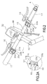
- FIG. 2 is an enlarged perspective view of a handle portion thereof;
- FIG. 2A is an enlarged detail A of Fig. 2.
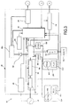
- FIG. 3 is a block diagram of part of a configuration of a control device;
- FIG. 4 is a block diagram of the remaining part of the configuration of the control device;
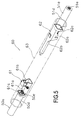
- FIG. 5 is an exploded perspective view of a configuration of a wiring connection structure according to the present invention before connection; and
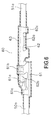
- FIG. 6 is a side view, partially in section, of a connection state of the wiring connection structure.
-
- 1 frame
- 4 handle portion (an example of a handle)
- 11 control device (an example of a second electrical component)
- 15 handlebar (an example of a configuration of a handle) 23a switch unit (an example of a first electrical component) 31 second control unit (an example of a configuration of a second electrical component)
- 50 first connection wiring
- 51 second connection wiring
- 60 wiring connection structure
- 61 first connection terminal
- 62 second connection terminal
- 63 cover member
- In FIG. 1, a bicycle adopting an embodiment of the present invention is a mountain bike with front and rear suspensions, and includes a
frame 1 having aframe body 2 with arear suspension 13r, afront fork 3 with afront suspension 13f, and a handle portion 4 (an example of a handle), adrive portion 5 including front andrear shift devices front wheel 6 mounted to thefront fork 3, arear wheel 7 to which ahub dynamo 10 is mounted, and a control device 11 (FIG. 3) for controllingportions including the front andrear shift devices - The
frame body 2 of theframe 1 is created by welding an odd-form rectangular pipe. Portions including asaddle 18 and thedrive portion 5 are mounted to theframe body 2. Thefront fork 3 is oscillably mounted around a tilted shaft in front of theframe body 2. - As shown in FIG. 2, the
handle portion 4 includes ahandle stem 12 secured to an upper portion of thefront fork 3, and ahandlebar 15 secured to thehandle stem 12. Brake levers 16 and grips 17 are mounted to opposite ends of thehandlebar 15. A switch unit (an example of a first electrical component) 23a having rear shift switches 20a and 20b for a manual shift operation of therear shift device 9 and anoperation switch 21a for switching an operation mode between an automatic shift mode and a manual shift mode, and a switch unit (an example of the first electrical component) 23b having front shift switches 20c and 20d for a manual shift operation of thefront shift device 8 and anoperation switch 21b for manually switching the degree of stiffness of thesuspensions shift switch 20a is a switch for shifting down arear derailleur 26r described later stepwise in a manual shift mode, and theshift switch 20b is a switch for shifting up the rear derailleur 26r stepwise. Theshift switch 20c is a switch for shifting down afront derailleur 26f described later stepwise in the manual shift mode, and theshift switch 20d is a switch for shifting up thefront derailleur 26f stepwise. - The
drive portion 5 has acrank 27 provided in a lower portion (a hanger portion) of theframe body 2, and the externally mounted front andrear shift devices front shift device 8 has three sprockets F1 to F3 mounted to the crank 27 and thefront derailleur 26f mounted to theframe body 2. Therear shift device 9 has amultistage gear 25 having, for example, eight sprockets R1 to R8, and therear derailleur 26r mounted to a rear portion of theframe body 2. Thecrank 27 has a gear crank 27a to which the three sprockets F1 to F3 are mounted and a left crank 27b. Thedrive portion 5 has achain 29 wound around any of the sprockets F1 to F3 and R1 to R8 of the gear crank 27a and themultistage gear 25. - For the sprockets F1 to F3 on the front side, the number of teeth is successively increased from the sprocket F1 having the smallest number of teeth, and the sprocket F3 having the largest number of teeth is placed on the outermost side. For the sprockets R1 to R8 on the rear side, the number of teeth is successively decreased from the sprocket R1 having the largest number of teeth, and the sprocket R8 having the smallest number of teeth is placed on the outermost side. In FIG. 1, the number of sprockets R1 to R8 are not precisely shown for simplicity of the drawing.
- A rotation detector (not shown) for detecting a rotation of the
crank 27 is mounted to the center of rotation on the side of the left crank 27b. The rotation detector has a lead switch 24 (FIG. 3) and a magnet (not shown) spaced in a rotation direction of thecrank 27 on the side of the center of rotation of thelead switch 24, and four pulses are output from thelead switch 24 for each rotation of thecrank 27. The rotation detector is provided so that a shift operation is performed only when thecrank 27 rotates because the externally mounted shift device cannot be shifted without the rotation of thecrank 27. - The
hub dynamo 10 of therear wheel 7 is a hub to which a brake disk of a disc brake and a freewheel to which themultistage gear 25 is mounted can be mounted, and has an AC generator 19 (FIG. 3) therein that generates electric power by rotation of therear wheel 7. - The
control device 11 controls theshift devices suspensions - As shown in FIGS. 3 and 4, the control device 11 (an example of a second electrical component) has three control units: first, second, and
third control units 30 to 32. Thefirst control unit 30 is connected to theAC generator 19. Thefirst control unit 30 is driven by electric power generated by theAC generator 19, and controls thefront derailleur 26f, therear derailleur 26r, and therear suspension 13r with the supplied electric power. Thefirst control unit 30 is connected to thesecond control unit 31, and supplies a control signal on the electric power to thesecond control unit 31 or thethird control unit 32. Specifically, the supplied electric power is turned on/off according to the control signal to output the control signal on the electric power. - The
second control unit 31 controls thefront suspension 13f according to a control signal sent from thefirst control unit 30, and mediates operation information of theswitches 20a to 20d, 21a, and 21b to thefirst control unit 30. - The
third control unit 32 is detachably mounted to thesecond control unit 31. Thethird control unit 32 has a liquidcrystal display portion 56 that can display traveling information, and controls the display on the liquidcrystal display portion 56 according to the control signal output from thefirst control unit 30. The liquidcrystal display portion 56 displays traveling information such as a vehicle speed, a traveling distance, or a shift position. - The
first control unit 30 is mounted to, for example, the hanger portion in the lower portion of theframe body 2, and provided adjacent to the rotation detector and thefront derailleur 26f. Thefirst control unit 30 controls theshift devices rear suspension 13r according to the operation mode. Specifically, in the automatic mode, thefirst control unit 30 controls the shift of theshift devices rear suspension 13r between high and low according to the speed. In the manual mode, thefirst control unit 30 controls theshift devices rear suspension 13r according to operations of the shift switches 20a to 20d and theoperation switch 21b. Also, a speed signal is output to thesecond control unit 31 and thethird control unit 32 as a control signal. - The
first control unit 30 has afirst control portion 35 constituted by a microcomputer including a CPU, a memory, an I/O interface, or the like. Awaveform shaping circuit 36 for generating a speed signal according to a pulse output from theAC generator 19, acharge control circuit 33, a firstpower storage element 38a, alead switch 24 of the rotation detector, a powersupply communication circuit 34, and a power on/offswitch 28 are connected to thefirst control portion 35. A motor driver (FMD) 39f of thefront derailleur 26f, amotordriver (RMD) 39r of therearderailleur26r, anoperation position sensor (FLS) 41f of thefront derailleur 26f, an operation position sensor (RLS) 41r of therear derailleur 26r, and a motor driver (RSD) 43r of therear suspension 13r are also connected to thefirst control portion 35. - Traveling data such as various traveling information and control data required for control are stored in the memory in the
first control portion 35. Electric power from a secondpower storage element 38b connected to the firstpower storage element 38a via adiode 42 is supplied to thefirst control portion 35. Thediode 42 is provided to pass an electric current in one direction only from the firstpower storage element 38a to the secondpower storage element 38b. This prevents backflow from the secondpower storage element 38b to the firstpower storage element 38a . The firstpower storage element 38a is mainly used as power supply for electrical equipment having high power consumption and large electric capacity such as themotor drivers suspensions derailleurs motor drivers power storage element 38a is also used as power supply for asecond control portion 45 described later. The secondpower storage element 38b is used as power supply for electrical equipment having low power consumption and small electric capacity such as thefirst control portion 35, athird control portion 55 described later, or the liquidcrystal display portion 56. - The first and second
power storage elements AC generator 19 and rectified by thecharge control circuit 33 . Thepower storage elements - The
charge control circuit 33 includes arectifier circuit 37 that rectifies the electric power output from theAC generator 19 and generates the DC power, and a charge on/offswitch 40 for turning on/off the electric power output from therectifier circuit 37 according to a voltage signal from thefirst control portion 35. The charge on/offswitch 40 is for preventing the firstpower storage element 38a from storing electric power of an excessive voltage. The voltage of the firstpower storage element 38a is monitored by thefirst control portion 35, and thefirst control portion 35 outputs a voltage signal for turning off the charge on/offswitch 40 when the monitored voltage reaches a predetermined voltage (for example, 7 volt) or more to open the charge on/offswitch 40. Thefirst control portion 35 outputs a voltage signal for turning on the charge on/offswitch 40 when the monitored voltage reaches a predetermined voltage (for example, 5.5 volt) or less to close the charge on/offswitch 40. - The power
supply communication circuit 34 is also connected to the secondpower storage element 38b. The powersupply communication circuit 34 turns on/off electric power supplied from the secondpower storage element 38b according to a control signal depending on information from thefirst control portion 35 on a speed, a distance, a shift stage, an automatic or manual operation, or the degree of stiffness of the suspension to supply electric power including the control signal to thesecond control unit 31. - The power on/off
switch 28 is also connected to the firstpower storage element 38a. The power on/offswitch 28 is provided to turn on/off the electric power supplied from the firstpower storage element 38a to themotor driver 43f of thefront suspension 13f and thesecond control unit 31. The power on/offswitch 28 is turned off by a signal from thefirst control portion 35 when control of the degree of stiffness of the front andrear suspensions power storage element 38a. - The
motor drivers motors derailleurs suspensions - As shown in FIG. 2, the
second control unit 31 is mounted by abracket 49 securable to thehandlebar 15 of thehandle portion 4. Thesecond control unit 31 has thesecond control portion 45 constituted by the microcomputer as shown in FIG. 4. Afirst receiving circuit 46 and the motor driver (FSD) 43f of thefront suspension 13f are connected to thesecond control portion 45. Thefirst receiving circuit 46 is connected to the powersupply communication circuit 34 of thefirst control unit 30, and extracts the control signal included in the electric power and output the signal to thesecond control portion 45 . The powersupply communication circuit 34 is also connected to the thirdpower storage element 38c. The thirdpower storage element 38c uses a relatively small capacity capacitor such as an electrolytic capacitor, and is provided to smooth the electric power turned on/off according to the control signal. Abuffer amplifier 48 is connected to the thirdpower storage element 38c. Thebuffer amplifier 48 is an amplifier that can maintain an input/output voltage at a constant level, and is provided to stabilize an analog voltage signal from the shift switches 20a and 20b and the operation switches 21a and 21b. - The
second control unit 31 is operated by the electric power from the firstpower storage element 38a, and controls thefront suspension 13f according to the operation mode based on the control signal on the electric power of the secondpower storage element 38b. Specifically, in the automatic mode, thesecond control unit 31 switches the degree of stiffness of thefront suspension 13f according to the speed, and in the manual shift mode, thesecond control unit 31 switches the degree of stiffness of thefront suspension 13f according to the operation of theoperation switch 21b. As described above, thesecond control portion 45 is operated by the power on/offswitch 28 only when the suspension is controlled. - The
third control unit 32 is a so-called cycle computer, and is detachably mounted to thesecond control unit 31. Abattery 59 such as a button battery is mounted to thethird control unit 32 so that electric power can be also supplied from thebattery 59. This allows thethird control unit 32 to be operated even if thethird control unit 32 is detached from thesecond control unit 31. Thus, various initial setting such as setting of a wheel diameter can be performed and various data such as a traveling distance or a traveling time can be stored. - As shown in FIG. 4, the
third control unit 32 has thethird control portion 55 constituted by the microcomputer. The liquidcrystal display portion 56, aback light 58, thebattery 59, asecond receiving circuit 64, and a fourthpower storage element 38d are connected to thethird control portion 55. The liquidcrystal display portion 56 can display various traveling information such as a speed, cadence, a traveling distance, a shift position, or the state of suspensions, and is illuminated by theback light 58. An electricpower stabilizing circuit 57 stabilizes electric power including anon/off signal by, for example, smoothing even if the electric power is turned on/off to supply the control signal. This prevents flickering of the back light 58 even if the on/off control signal is on the electric power. - The
second receiving circuit 64 is connected in parallel with thefirst receiving circuit 46, and extract a control signal included in the electric power from the secondpower storage element 38b and outputs the signal to thethird control portion 55. The fourthpower storage element 38d is constituted by, for example, an electrolytic capacitor, and provided to store the electric power supplied from the secondpower storage element 38b to reduce influence of the on/off control signal. The fourthpower storage element 38d is connected in parallel with thesecond receiving circuit 64 and connected to thethird control portion 55 and the electricpower stabilizing circuit 57. - For the
control device 11 having such a configuration, theAC generator 19 of thehub dynamo 10 generates electric power when the bicycle travels, the electric power is fed to thefirst control unit 30 and stored in the first and secondpower storage elements AC generator 19 is provided in therear wheel 7, and thus the first and secondpower storage elements crystal display portion 56 even if the amount of charge is insufficient. - The
first control unit 30 is provided in the hanger portion, and is close to theAC generator 19. Thus, a short power supply cable may be used to increase efficiency of transmission of signals and electric power supply. - When the operation switches 21a and 21b or the shift switches 20a to 20dare operated, a signal of a different analog voltage is output to the
first control portion 35 via thebuffer amplifier 48, and thefirst control portion 35 generates signals for controlling thederailleurs suspensions 13f and 13, or a signal for changing the mode. Among the signals, the signal for controlling thefront suspension 13f is output to the powersupply communication circuit 34, turns on/off the electric power like the speed signal, and is output to thesecond control portion 45 to control thefront suspension 13f in thesecond control portion 45. - As shown in an enlarged manner in a portion A in FIG. 2, a 3-wire first
electrical wiring 50 is connected to theswitch unit 23a. The firstelectrical wiring 50 is connected to the shift switches 20a and 20b and theoperation switch 21a in theswitch unit 23a. Specifically, afirst cord 50a of the firstelectrical wiring 50 is connected to one end of theoperation switch 21a, and asecond cord 50b is connected to one ends of the shift switches 20a and 20b via resistances with different values. Athird cord 50c is a common wire, and connected to the other ends of theoperation switch 21a and the shift switches 20a and 20b. Such connection causes an analog signal according to the on/off operation of theoperation switch 21a is output from thefirst cord 50a to thebuffer amplifier 48, and a signal of a different analog voltage according to the on/off operation of the shift switches 20a and 20b is output from thesecond cord 50c to the buf fer ampl i fier 48. The firstelectrical wiring 50 is inserted into thehandlebar 15 via a through hole formed to pass from theswitch unit 23a to thehandlebar 15 through inner and outer peripheries and drawn out from an end surface of thehandlebar 15. The same first electrical wiring is also connected to theswitch unit 23b. - A second
electrical wiring 51 electrically connected to the firstelectrical wiring 50 by awiring connection structure 60 is connected to thesecond control unit 31 mounted to thebracket 49. The secondelectrical wiring 51 is also a 3-wire wiring and connected to thebuffer amplifier 48. - The
wiring connection structure 60 electrically connects the firstelectrical wiring 50 connected to theswitch unit 23a mounted to thehandlebar 15 and the secondelectrical wiring 51 connected to thesecond control unit 31. As shown in FIG. 5, thewiring connection structure 60 has afirst connection terminal 61 electrically connectable to thecords electrical wiring 50, asecond connection terminal 62 electrically connectable tocords electrical wiring 51 and thefirst connection terminal 61, and a heat-shrinkable synthetic resintubular cover member 63 covering at least both theconnection terminals wiring connection structure 60 is shown in which thefirst cord 50a of the firstelectrical wiring 50 and thefirst cord 51a of the secondelectrical wiring 51 are electrically connected, but other cords and a wiring connection structure connecting the cords have the same structures. As described above, the first electrical wiring and the second electrical wiring are connected to theswitch unit 23b and thesecond control unit 31, and these electrical wirings are connected by awiring connection structure 60 having the same configuration. - Both the
connection terminals first connection terminal 61 is a socket type (female) connection terminal, and the second connection terminal is a plug type (male) connection terminal. Both theconnection terminals - The
first connection terminal 61 has afirst crimp portion 61a to which thefirst cord 50a of the firstelectrical wiring 50 can be crimped, a socket-shapedfirst connection portion 61b placed next to thefirst crimp portion 61a and connectable to thesecond connection terminal 62, and a first covering and securingportion 61c for securing acover portion 50d of thefirst cord 50a. The first covering and securingportion 61c is placednext to thefirst crimp portion 61a on the opposite side to thefirst connection portion 61b. Thefirst crimp portion 61a electrically connects acore wire 50e of thefirst cord 50a by folding a plate by a crimp tool. - The
second connection terminal 62 includes asecond crimp portion 62a to which thefirst cord 51a of the secondelectrical wiring 51 can be crimped, and a plug-shaped taperedsecond connection portion 62b placed next to thesecond crimp portion 62a and inserted into and electrically connectable to thefirst connection portion 61b of thefirst connection terminal 61, and a second covering and securingportion 62c for securing acover portion 51d of thefirst cord 51a. The second covering and securingportion 62c is placed next to thesecond crimp portion 62a on the opposite side to thesecond connection portion 62b. Thesecond crimp portion 62a electrically connects acore wire 51e of thefirst cord 51a by folding a plate by a crimp tool. - The
cover member 63 is, for example, a heat-shrinkable transparent polyolefin resin tube, and has sufficient length to cover the first andsecond crimp portions second connection portions portions electrical wirings cover member 63 causes thecover member 63 to shrink with heat substantially along the shape of theconnection terminals cords - For connecting the first
electrical wiring 50 and the secondelectrical wiring 51 with thewiring connection structure 60 thus configured, the following connection operation is performed. - First, through holes (not shown) through which the electrical wirings are inserted are previously bored in an outer peripheral surface of the
handlebar 15 near portions to which thesecond control unit 31 and theswitch units electrical wire 50 connected to theswitch unit 23a is passed into thehandlebar 15 through the through hole, and drawn out from the end surface of thehandlebar 15. Similarly, the secondelectrical wiring 51 connected to thesecond control unit 31 is passed into thehandlebar 15 through the through hole, and drawn out from the end surface of thehandlebar 15. Then, core wires are exposed of thecords 50a to 50c and 51a to 51c of the first and secondelectrical wirings first connection terminal 61 is crimped to thecords 50a to 50c of the firstelectrical wiring 50, and thesecond connection terminal 62 is crimped to thecords 51a to 51c of the secondelectrical wiring 51. Then, thecover member 63 before heat shrinkage is mounted to any of the cords to connect theconnection terminals connection terminals cover member 63. Then, the hot air is used to cause thecover member 63 to shrink with heat along the shape of the connection terminals and the cords and come into close contact with outer diameters thereof. Finally, the electrical wirings connected are accommodated in thehandlebar 15, and thegrips 17 are mounted to thehandlebar 15 to finish the wiring. - Here, the heat-shrinkable synthetic resin cover member covers at least both the connection terminals. Thus, the connected connection terminals are covered with the cover member and heated to allow the cover member to shrink substantially along the shape of the connection terminals. This facilitates providing a waterproof structure and prevents poor insulation or falling off of the wirings.
- The first and second
electrical wirings switch unit 23a and thesecond control unit 31, and then drawn out of thehandlebar 15 that constitutes theframe 1 from the positions to which theswitch unit 23a and thesecond control unit 31 are mounted through the inside of thehandlebar 15, and the two firstelectrical wirings second connection terminals handlebar 15, thereby facilitating the insertion of the electrical wirings into thehandlebar 15. At this time, both theconnection terminals resin cover member 63, thereby maintaining insulation and waterproof properties and preventing theconnection terminals electrical wirings -
- (a) In the above described embodiment, the
switch unit 23a and thesecond control unit 31 mounted to thehandlebar 15 are illustrated as the electrical components mounted to the frame, but an electrical component connected to the wiring connection structure according to the present invention may be of any type as long as the electrical component is mountable to the frame. - (b) In the above described embodiment, the connection terminals connected by the male and female fitting are illustrated, but a connection structure of the connection terminals is not limited to the male and female fitting. For example, a structure with connection terminals being connected by a screw or caulking may be used. The connection structure of the connection terminal to the electrical wiring is not limited to the crimp, but a connection structure by a screw or soldering may be used.
- List of cited reference numerals
- FIG. 2
- #1
- PORTION A
- FIG. 3
- 24
- LEAD SWITCH
- 28
- POWER ON/OFF SWITCH
- 33
- CHARGE CONTROL CIRCUIT
- 34
- POWER SUPPLY COMMUNICATION CIRCUIT
- 35
- FIRST CONTROL PORTION
- 36
- WAVEFORM SHAPING CIRCUIT
- 37
- RECTIFIER CIRCUIT
- 38a
- FIRST POWER STORAGE ELEMENT
- 38b
- SECOND POWER STORAGE ELEMENT
- 40
- CHARGE ON/OFF SWITCH
- FIG. 4
- 20a to 20d
- SHIFT SWITCH
- 21a, 21b
- OPERATION SWITCH
- 38c
- THIRD POWER STORAGE ELEMENT
- 38d
- FOURTH POWER STORAGE ELEMENT
- 45
- SECOND CONTROL PORTION
- 46
- FIRST RECEIVING CIRCUIT
- 55
- THIRD CONTROL PORTION
- 56
- LIQUID CRYSTAL DISPLAY PORTION
- 57
- ELECTRIC POWER STABILIZING CIRCUIT
- 58
- BACK LIGHT
- 59
- BATTERY
- 64
- SECOND RECEIVING CIRCUIT
Claims (5)
- A wiring connection structure for a bicycle for electrically connecting a first electrical wiring connected to a first electrical component mounted to a frame of the bicycle including a handle and a second electrical wiring connected to a second electrical component, comprising:a first connection terminal (61) electrically connectable to said first electrical wiring (50);a second connection terminal (62) electrically connectable to said second electrical wiring (51) and said first connection terminal; anda heat-shrinkable synthetic resin tubular cover member (63) covering at least both said connection terminals.
- The wiring connection structure for a bicycle according to claim 1, wherein said first connection terminal (61) includes a first crimp portion (61a) to which said first electrical wiring can be crimped, and a first connection portion (61b) placed next to said first crimp portion and connectable to said second connection terminal by male and female fitting,
said second connection terminal (62) includes a second crimp portion (62a) to which said second electrical wiring can be crimped, and a second connection portion (62b) placed next to said second crimp portion and connectable to said first connection terminal by male and female fitting, and
said cover member (63) has sufficient length to cover at least said first and second crimp portions and said first and second connection portions with both said connection terminals being connected. - The wiring connection structure for a bicycle according to claim 1 or 2, wherein said first and second connection terminals (61, 62) and said cover member (63) can be accommodated in said frame.
- The wiring connection structure for a bicycle according to claim 3, wherein said first electrical component is a shift operation portion having a shift operation switch (20a-20d) mounted to said handle, said second electrical component is a shift control portion (11) that outputs a shift signal to a shift device by an on/off operation of said switch mounted to said handle, and
said first and second connection terminals and said cover member can be accommodated in said handle (4). - The wiring connection structure for a bicycle according to any one of claims 1 to 4, wherein said cover member (63) is made of transparent polyolefin resin.
Applications Claiming Priority (1)
| Application Number | Priority Date | Filing Date | Title |
|---|---|---|---|
| JP2005055516A JP2006244743A (en) | 2005-03-01 | 2005-03-01 | Wiring connection structure for bicycle |
Publications (2)
| Publication Number | Publication Date |
|---|---|
| EP1698546A2 true EP1698546A2 (en) | 2006-09-06 |
| EP1698546A3 EP1698546A3 (en) | 2008-10-29 |
Family
ID=36570405
Family Applications (1)
| Application Number | Title | Priority Date | Filing Date |
|---|---|---|---|
| EP06110458A Withdrawn EP1698546A3 (en) | 2005-03-01 | 2006-02-27 | Wiring connection structure for bicycle |
Country Status (6)
| Country | Link |
|---|---|
| US (1) | US7354320B2 (en) |
| EP (1) | EP1698546A3 (en) |
| JP (1) | JP2006244743A (en) |
| CN (1) | CN100511851C (en) |
| BR (1) | BRPI0600549A (en) |
| TW (1) | TWI288726B (en) |
Cited By (3)
| Publication number | Priority date | Publication date | Assignee | Title |
|---|---|---|---|---|
| EP2105377A3 (en) * | 2008-03-24 | 2009-11-11 | Shimano, Inc. | Bar end electric shifter |
| CN102742083A (en) * | 2010-02-05 | 2012-10-17 | 古河电气工业株式会社 | Crimp terminal, connection structure, and method of manufacturing crimp terminal |
| US8297143B2 (en) | 2009-05-19 | 2012-10-30 | Shimano Inc. | Electrical bicycle shift control device |
Families Citing this family (17)
| Publication number | Priority date | Publication date | Assignee | Title |
|---|---|---|---|---|
| JP3950875B2 (en) * | 2004-07-28 | 2007-08-01 | 株式会社シマノ | Bicycle electrical wiring support structure |
| DE102007008740B3 (en) * | 2007-02-22 | 2008-07-24 | Siemens Ag | Electrical connector has spike protection with partly metallic housing, which has cable-lateral and plug-lateral end, and dielectric material sleeve surrounds total connector |
| ITMI20071352A1 (en) * | 2007-07-06 | 2009-01-07 | Campagnolo Srl | INSTRUMENTATION KIT OF A BICYCLE AND BICYCLE INCLUDING SUCH A KIT |
| KR101297192B1 (en) * | 2008-11-10 | 2013-08-19 | 삼성전자주식회사 | Image forming apparatus, chip, and chip package |
| JP5299262B2 (en) * | 2009-12-24 | 2013-09-25 | 日立電線株式会社 | Connection structure |
| US8655548B2 (en) * | 2011-03-31 | 2014-02-18 | Shimano Inc. | Bicycle component control apparatus |
| US8402664B1 (en) * | 2011-10-28 | 2013-03-26 | Shimano Inc. | Electric control device |
| TWI487644B (en) * | 2013-01-09 | 2015-06-11 | Nat Univ Chung Hsing | Bike with brain wave controllable speed changing system |
| TWI487646B (en) * | 2013-01-09 | 2015-06-11 | Nat Univ Chung Hsing | Bike with vocal controllable speed changing system |
| US20140252746A1 (en) * | 2013-03-06 | 2014-09-11 | Specialized Bicycle Components, Inc. | Bicycle electronic display and shift lever mount |
| US9215847B2 (en) | 2013-06-11 | 2015-12-22 | Wesley Allen Bainter | Apparatus for anchoring an irrigation tower |
| DE102013014091B4 (en) * | 2013-08-27 | 2023-05-11 | Dt Swiss Ag | Suspension control for a two-wheeler and method |
| US10046826B2 (en) * | 2015-08-27 | 2018-08-14 | Tektro Technology Corporation | Dual control lever and bicycle control assembly |
| JP2018052356A (en) * | 2016-09-29 | 2018-04-05 | 株式会社シマノ | Bicycle control device |
| JP6965072B2 (en) * | 2017-09-15 | 2021-11-10 | ヤマハ発動機株式会社 | Bicycle and stem assembly |
| CN110165464A (en) * | 2019-06-01 | 2019-08-23 | 上海晗普新材料科技有限公司 | A kind of pyrocondensation socket terminal |
| CN115472982B (en) * | 2021-06-11 | 2023-07-21 | 浙江晶科能源有限公司 | Shell of energy storage battery, energy storage battery and energy storage system |
Citations (3)
| Publication number | Priority date | Publication date | Assignee | Title |
|---|---|---|---|---|
| GB799370A (en) * | 1956-05-18 | 1958-08-06 | Ward Goldstone Ltd | Improvements in or relating to electric two-part couplings |
| JP2000251966A (en) * | 1999-03-01 | 2000-09-14 | Yazaki Corp | Electronic control unit for wiring harness installation |
| JP2004159490A (en) | 2002-09-12 | 2004-06-03 | Shimano Inc | Power supply for bicycle |
Family Cites Families (18)
| Publication number | Priority date | Publication date | Assignee | Title |
|---|---|---|---|---|
| JPS5985017U (en) * | 1982-11-29 | 1984-06-08 | 住友電気工業株式会社 | Half-split heat shrinkable sleeve fixing tool |
| US4778948A (en) * | 1983-08-04 | 1988-10-18 | Raychem Limited | Cable joint |
| US4760372A (en) * | 1987-04-17 | 1988-07-26 | Watson Harry D | Bicycle indicator system |
| US4965410A (en) * | 1989-02-06 | 1990-10-23 | Minnesota Mining And Manufacturing Company | Dam for shield terminators |
| GB9002629D0 (en) * | 1990-02-06 | 1990-04-04 | Raychem Pontoise Sa | Electrical connection |
| JP2005053363A (en) * | 2003-08-05 | 2005-03-03 | Shimano Inc | Hollow structural component part bicycle |
| US5267869A (en) * | 1992-12-14 | 1993-12-07 | General Motors Corporation | Ignition cable assembly and method of making same |
| US5370412A (en) * | 1993-08-10 | 1994-12-06 | Chou; Ming-Fu | Ergonomically superior bicycle meter assembly |
| JP3368655B2 (en) * | 1994-02-25 | 2003-01-20 | スズキ株式会社 | Electric tricycle |
| JPH08213082A (en) * | 1994-10-21 | 1996-08-20 | Whitaker Corp:The | Electric terminal and electric connector using the same |
| US6017989A (en) * | 1997-04-01 | 2000-01-25 | The Standard Products Company | Exterior automotive component of an elastomeric modified polyolefin material having pleasing appearance |
| JP3080222B2 (en) * | 1997-06-24 | 2000-08-21 | 株式会社シマノ | Bicycle flat cable connector |
| JP3382832B2 (en) * | 1997-11-27 | 2003-03-04 | 川崎重工業株式会社 | Mounted four-wheel rough terrain vehicle |
| US6648686B2 (en) * | 2000-11-30 | 2003-11-18 | Shimano Inc. | Electrical connector |
| US6523772B2 (en) * | 2001-05-29 | 2003-02-25 | Shimano Inc. | Electric device with cord retainer for bicycle |
| CA2355972C (en) * | 2001-08-24 | 2009-11-17 | Shawcor Ltd. | Ionomer-insulated electrical connectors |
| JP3645876B2 (en) * | 2002-08-30 | 2005-05-11 | 株式会社シマノ | Bicycle electrical equipment control device |
| US6983949B2 (en) * | 2004-05-19 | 2006-01-10 | Shimano Inc. | Bicycle headset structure |
-
2005
- 2005-03-01 JP JP2005055516A patent/JP2006244743A/en active Pending
-
2006
- 2006-01-10 TW TW095100921A patent/TWI288726B/en not_active IP Right Cessation
- 2006-02-13 CN CNB2006100042692A patent/CN100511851C/en not_active Expired - Fee Related
- 2006-02-24 BR BRPI0600549-7A patent/BRPI0600549A/en not_active IP Right Cessation
- 2006-02-27 US US11/363,862 patent/US7354320B2/en not_active Expired - Fee Related
- 2006-02-27 EP EP06110458A patent/EP1698546A3/en not_active Withdrawn
Patent Citations (3)
| Publication number | Priority date | Publication date | Assignee | Title |
|---|---|---|---|---|
| GB799370A (en) * | 1956-05-18 | 1958-08-06 | Ward Goldstone Ltd | Improvements in or relating to electric two-part couplings |
| JP2000251966A (en) * | 1999-03-01 | 2000-09-14 | Yazaki Corp | Electronic control unit for wiring harness installation |
| JP2004159490A (en) | 2002-09-12 | 2004-06-03 | Shimano Inc | Power supply for bicycle |
Cited By (8)
| Publication number | Priority date | Publication date | Assignee | Title |
|---|---|---|---|---|
| EP2105377A3 (en) * | 2008-03-24 | 2009-11-11 | Shimano, Inc. | Bar end electric shifter |
| US7908940B2 (en) | 2008-03-24 | 2011-03-22 | Shimano Inc. | Bar end electric shifter |
| EP2500255A1 (en) * | 2008-03-24 | 2012-09-19 | Shimano Inc. | Bar end electric shifter |
| US8297143B2 (en) | 2009-05-19 | 2012-10-30 | Shimano Inc. | Electrical bicycle shift control device |
| TWI383919B (en) * | 2009-05-19 | 2013-02-01 | Shimano Kk | Electrical bicycle shift control device |
| CN102742083A (en) * | 2010-02-05 | 2012-10-17 | 古河电气工业株式会社 | Crimp terminal, connection structure, and method of manufacturing crimp terminal |
| EP2533364A4 (en) * | 2010-02-05 | 2014-06-18 | Furukawa Electric Co Ltd | CRIMPING TERMINAL, CONNECTING STRUCTURE, AND METHOD FOR MANUFACTURING CRIMPING TERMINAL |
| CN102742083B (en) * | 2010-02-05 | 2015-05-20 | 古河电气工业株式会社 | Crimp terminal, connection structure, and method of manufacturing crimp terminal |
Also Published As
| Publication number | Publication date |
|---|---|
| CN1829003A (en) | 2006-09-06 |
| BRPI0600549A (en) | 2007-07-17 |
| US7354320B2 (en) | 2008-04-08 |
| EP1698546A3 (en) | 2008-10-29 |
| TWI288726B (en) | 2007-10-21 |
| CN100511851C (en) | 2009-07-08 |
| TW200637762A (en) | 2006-11-01 |
| JP2006244743A (en) | 2006-09-14 |
| US20060211282A1 (en) | 2006-09-21 |
Similar Documents
| Publication | Publication Date | Title |
|---|---|---|
| US7354320B2 (en) | Wiring connection structure for bicycle | |
| US7147238B2 (en) | Bicycle part with a partitioned chamber | |
| US6835069B2 (en) | Apparatus for wiring bicycle electrical components | |
| EP1398266B1 (en) | Bicycle power supply | |
| EP1520773B1 (en) | Electrical component holder for bicycle | |
| US6418041B1 (en) | Bicycle power supply | |
| US7410278B2 (en) | Bicycle light assembly with auxiliary output connector | |
| JP3727315B2 (en) | Bicycle power supply | |
| EP1463013A2 (en) | Bicycle information processing apparatus with memory protection | |
| EP1452431A1 (en) | Bicycle display apparatus with distributed processing | |
| TWI785123B (en) | Wireless components for bicycles | |
| EP2452866A1 (en) | Derailleuer cable detecting assembly for an electric-auxiliary bicycle | |
| EP1452440B1 (en) | Bicycle shift control apparatus | |
| CN110316312B (en) | Assembly for human powered vehicle | |
| EP3470316A1 (en) | Grip for a bike | |
| JP2008001229A (en) | Gear shift control device for bicycle and gear shift control method for bicycle | |
| TW200415070A (en) | Electronic control device for bicycle | |
| EP1391375B1 (en) | Power stabilizing apparatus for a bicycle electrical component | |
| EP0686549A1 (en) | Charging connector mounting structure of motor-assisted bicycle | |
| US12116085B1 (en) | Component for human-powered vehicle | |
| CN112478031A (en) | Power supply apparatus for human powered vehicle | |
| JPH08183490A (en) | Vehicle battery storage device |
Legal Events
| Date | Code | Title | Description |
|---|---|---|---|
| PUAI | Public reference made under article 153(3) epc to a published international application that has entered the european phase |
Free format text: ORIGINAL CODE: 0009012 |
|
| AK | Designated contracting states |
Kind code of ref document: A2 Designated state(s): AT BE BG CH CY CZ DE DK EE ES FI FR GB GR HU IE IS IT LI LT LU LV MC NL PL PT RO SE SI SK TR |
|
| AX | Request for extension of the european patent |
Extension state: AL BA HR MK YU |
|
| PUAL | Search report despatched |
Free format text: ORIGINAL CODE: 0009013 |
|
| AK | Designated contracting states |
Kind code of ref document: A3 Designated state(s): AT BE BG CH CY CZ DE DK EE ES FI FR GB GR HU IE IS IT LI LT LU LV MC NL PL PT RO SE SI SK TR |
|
| AX | Request for extension of the european patent |
Extension state: AL BA HR MK YU |
|
| 17P | Request for examination filed |
Effective date: 20090211 |
|
| AKX | Designation fees paid |
Designated state(s): DE IT |
|
| 17Q | First examination report despatched |
Effective date: 20110714 |
|
| STAA | Information on the status of an ep patent application or granted ep patent |
Free format text: STATUS: THE APPLICATION IS DEEMED TO BE WITHDRAWN |
|
| 18D | Application deemed to be withdrawn |
Effective date: 20120515 |