EP1698306B1 - Surgical introducer - Google Patents
Surgical introducer Download PDFInfo
- Publication number
- EP1698306B1 EP1698306B1 EP05257767A EP05257767A EP1698306B1 EP 1698306 B1 EP1698306 B1 EP 1698306B1 EP 05257767 A EP05257767 A EP 05257767A EP 05257767 A EP05257767 A EP 05257767A EP 1698306 B1 EP1698306 B1 EP 1698306B1
- Authority
- EP
- European Patent Office
- Prior art keywords
- head
- acetabular cup
- cup
- rim
- holding element
- Prior art date
- Legal status (The legal status is an assumption and is not a legal conclusion. Google has not performed a legal analysis and makes no representation as to the accuracy of the status listed.)
- Expired - Lifetime
Links
Images


Classifications
-
- A—HUMAN NECESSITIES
- A61—MEDICAL OR VETERINARY SCIENCE; HYGIENE
- A61F—FILTERS IMPLANTABLE INTO BLOOD VESSELS; PROSTHESES; DEVICES PROVIDING PATENCY TO, OR PREVENTING COLLAPSING OF, TUBULAR STRUCTURES OF THE BODY, e.g. STENTS; ORTHOPAEDIC, NURSING OR CONTRACEPTIVE DEVICES; FOMENTATION; TREATMENT OR PROTECTION OF EYES OR EARS; BANDAGES, DRESSINGS OR ABSORBENT PADS; FIRST-AID KITS
- A61F2/00—Filters implantable into blood vessels; Prostheses, i.e. artificial substitutes or replacements for parts of the body; Appliances for connecting them with the body; Devices providing patency to, or preventing collapsing of, tubular structures of the body, e.g. stents
- A61F2/02—Prostheses implantable into the body
- A61F2/30—Joints
- A61F2/46—Special tools for implanting artificial joints
- A61F2/4603—Special tools for implanting artificial joints for insertion or extraction of endoprosthetic joints or of accessories thereof
- A61F2/4609—Special tools for implanting artificial joints for insertion or extraction of endoprosthetic joints or of accessories thereof of acetabular cups
-
- A—HUMAN NECESSITIES
- A61—MEDICAL OR VETERINARY SCIENCE; HYGIENE
- A61F—FILTERS IMPLANTABLE INTO BLOOD VESSELS; PROSTHESES; DEVICES PROVIDING PATENCY TO, OR PREVENTING COLLAPSING OF, TUBULAR STRUCTURES OF THE BODY, e.g. STENTS; ORTHOPAEDIC, NURSING OR CONTRACEPTIVE DEVICES; FOMENTATION; TREATMENT OR PROTECTION OF EYES OR EARS; BANDAGES, DRESSINGS OR ABSORBENT PADS; FIRST-AID KITS
- A61F2/00—Filters implantable into blood vessels; Prostheses, i.e. artificial substitutes or replacements for parts of the body; Appliances for connecting them with the body; Devices providing patency to, or preventing collapsing of, tubular structures of the body, e.g. stents
- A61F2/02—Prostheses implantable into the body
- A61F2/30—Joints
- A61F2/32—Joints for the hip
- A61F2/34—Acetabular cups
-
- A—HUMAN NECESSITIES
- A61—MEDICAL OR VETERINARY SCIENCE; HYGIENE
- A61F—FILTERS IMPLANTABLE INTO BLOOD VESSELS; PROSTHESES; DEVICES PROVIDING PATENCY TO, OR PREVENTING COLLAPSING OF, TUBULAR STRUCTURES OF THE BODY, e.g. STENTS; ORTHOPAEDIC, NURSING OR CONTRACEPTIVE DEVICES; FOMENTATION; TREATMENT OR PROTECTION OF EYES OR EARS; BANDAGES, DRESSINGS OR ABSORBENT PADS; FIRST-AID KITS
- A61F2/00—Filters implantable into blood vessels; Prostheses, i.e. artificial substitutes or replacements for parts of the body; Appliances for connecting them with the body; Devices providing patency to, or preventing collapsing of, tubular structures of the body, e.g. stents
- A61F2/02—Prostheses implantable into the body
- A61F2/30—Joints
- A61F2/46—Special tools for implanting artificial joints
- A61F2/4603—Special tools for implanting artificial joints for insertion or extraction of endoprosthetic joints or of accessories thereof
-
- A—HUMAN NECESSITIES
- A61—MEDICAL OR VETERINARY SCIENCE; HYGIENE
- A61F—FILTERS IMPLANTABLE INTO BLOOD VESSELS; PROSTHESES; DEVICES PROVIDING PATENCY TO, OR PREVENTING COLLAPSING OF, TUBULAR STRUCTURES OF THE BODY, e.g. STENTS; ORTHOPAEDIC, NURSING OR CONTRACEPTIVE DEVICES; FOMENTATION; TREATMENT OR PROTECTION OF EYES OR EARS; BANDAGES, DRESSINGS OR ABSORBENT PADS; FIRST-AID KITS
- A61F2/00—Filters implantable into blood vessels; Prostheses, i.e. artificial substitutes or replacements for parts of the body; Appliances for connecting them with the body; Devices providing patency to, or preventing collapsing of, tubular structures of the body, e.g. stents
- A61F2/02—Prostheses implantable into the body
- A61F2/30—Joints
- A61F2002/30001—Additional features of subject-matter classified in A61F2/28, A61F2/30 and subgroups thereof
- A61F2002/30316—The prosthesis having different structural features at different locations within the same prosthesis; Connections between prosthetic parts; Special structural features of bone or joint prostheses not otherwise provided for
- A61F2002/30535—Special structural features of bone or joint prostheses not otherwise provided for
- A61F2002/30589—Sealing means
-
- A—HUMAN NECESSITIES
- A61—MEDICAL OR VETERINARY SCIENCE; HYGIENE
- A61F—FILTERS IMPLANTABLE INTO BLOOD VESSELS; PROSTHESES; DEVICES PROVIDING PATENCY TO, OR PREVENTING COLLAPSING OF, TUBULAR STRUCTURES OF THE BODY, e.g. STENTS; ORTHOPAEDIC, NURSING OR CONTRACEPTIVE DEVICES; FOMENTATION; TREATMENT OR PROTECTION OF EYES OR EARS; BANDAGES, DRESSINGS OR ABSORBENT PADS; FIRST-AID KITS
- A61F2/00—Filters implantable into blood vessels; Prostheses, i.e. artificial substitutes or replacements for parts of the body; Appliances for connecting them with the body; Devices providing patency to, or preventing collapsing of, tubular structures of the body, e.g. stents
- A61F2/02—Prostheses implantable into the body
- A61F2/30—Joints
- A61F2/30767—Special external or bone-contacting surface, e.g. coating for improving bone ingrowth
- A61F2/30771—Special external or bone-contacting surface, e.g. coating for improving bone ingrowth applied in original prostheses, e.g. holes or grooves
- A61F2002/30795—Blind bores, e.g. of circular cross-section
-
- A—HUMAN NECESSITIES
- A61—MEDICAL OR VETERINARY SCIENCE; HYGIENE
- A61F—FILTERS IMPLANTABLE INTO BLOOD VESSELS; PROSTHESES; DEVICES PROVIDING PATENCY TO, OR PREVENTING COLLAPSING OF, TUBULAR STRUCTURES OF THE BODY, e.g. STENTS; ORTHOPAEDIC, NURSING OR CONTRACEPTIVE DEVICES; FOMENTATION; TREATMENT OR PROTECTION OF EYES OR EARS; BANDAGES, DRESSINGS OR ABSORBENT PADS; FIRST-AID KITS
- A61F2/00—Filters implantable into blood vessels; Prostheses, i.e. artificial substitutes or replacements for parts of the body; Appliances for connecting them with the body; Devices providing patency to, or preventing collapsing of, tubular structures of the body, e.g. stents
- A61F2/02—Prostheses implantable into the body
- A61F2/30—Joints
- A61F2/30767—Special external or bone-contacting surface, e.g. coating for improving bone ingrowth
- A61F2/30771—Special external or bone-contacting surface, e.g. coating for improving bone ingrowth applied in original prostheses, e.g. holes or grooves
- A61F2002/30795—Blind bores, e.g. of circular cross-section
- A61F2002/308—Blind bores, e.g. of circular cross-section oblong
-
- A—HUMAN NECESSITIES
- A61—MEDICAL OR VETERINARY SCIENCE; HYGIENE
- A61F—FILTERS IMPLANTABLE INTO BLOOD VESSELS; PROSTHESES; DEVICES PROVIDING PATENCY TO, OR PREVENTING COLLAPSING OF, TUBULAR STRUCTURES OF THE BODY, e.g. STENTS; ORTHOPAEDIC, NURSING OR CONTRACEPTIVE DEVICES; FOMENTATION; TREATMENT OR PROTECTION OF EYES OR EARS; BANDAGES, DRESSINGS OR ABSORBENT PADS; FIRST-AID KITS
- A61F2/00—Filters implantable into blood vessels; Prostheses, i.e. artificial substitutes or replacements for parts of the body; Appliances for connecting them with the body; Devices providing patency to, or preventing collapsing of, tubular structures of the body, e.g. stents
- A61F2/02—Prostheses implantable into the body
- A61F2/30—Joints
- A61F2/30767—Special external or bone-contacting surface, e.g. coating for improving bone ingrowth
- A61F2/30771—Special external or bone-contacting surface, e.g. coating for improving bone ingrowth applied in original prostheses, e.g. holes or grooves
- A61F2002/30795—Blind bores, e.g. of circular cross-section
- A61F2002/30807—Plurality of blind bores
-
- A—HUMAN NECESSITIES
- A61—MEDICAL OR VETERINARY SCIENCE; HYGIENE
- A61F—FILTERS IMPLANTABLE INTO BLOOD VESSELS; PROSTHESES; DEVICES PROVIDING PATENCY TO, OR PREVENTING COLLAPSING OF, TUBULAR STRUCTURES OF THE BODY, e.g. STENTS; ORTHOPAEDIC, NURSING OR CONTRACEPTIVE DEVICES; FOMENTATION; TREATMENT OR PROTECTION OF EYES OR EARS; BANDAGES, DRESSINGS OR ABSORBENT PADS; FIRST-AID KITS
- A61F2/00—Filters implantable into blood vessels; Prostheses, i.e. artificial substitutes or replacements for parts of the body; Appliances for connecting them with the body; Devices providing patency to, or preventing collapsing of, tubular structures of the body, e.g. stents
- A61F2/02—Prostheses implantable into the body
- A61F2/30—Joints
- A61F2/30767—Special external or bone-contacting surface, e.g. coating for improving bone ingrowth
- A61F2/30771—Special external or bone-contacting surface, e.g. coating for improving bone ingrowth applied in original prostheses, e.g. holes or grooves
- A61F2002/30795—Blind bores, e.g. of circular cross-section
- A61F2002/30807—Plurality of blind bores
- A61F2002/30808—Plurality of blind bores parallel
-
- A—HUMAN NECESSITIES
- A61—MEDICAL OR VETERINARY SCIENCE; HYGIENE
- A61F—FILTERS IMPLANTABLE INTO BLOOD VESSELS; PROSTHESES; DEVICES PROVIDING PATENCY TO, OR PREVENTING COLLAPSING OF, TUBULAR STRUCTURES OF THE BODY, e.g. STENTS; ORTHOPAEDIC, NURSING OR CONTRACEPTIVE DEVICES; FOMENTATION; TREATMENT OR PROTECTION OF EYES OR EARS; BANDAGES, DRESSINGS OR ABSORBENT PADS; FIRST-AID KITS
- A61F2/00—Filters implantable into blood vessels; Prostheses, i.e. artificial substitutes or replacements for parts of the body; Appliances for connecting them with the body; Devices providing patency to, or preventing collapsing of, tubular structures of the body, e.g. stents
- A61F2/02—Prostheses implantable into the body
- A61F2/30—Joints
- A61F2/30767—Special external or bone-contacting surface, e.g. coating for improving bone ingrowth
- A61F2/30771—Special external or bone-contacting surface, e.g. coating for improving bone ingrowth applied in original prostheses, e.g. holes or grooves
- A61F2002/3082—Grooves
-
- A—HUMAN NECESSITIES
- A61—MEDICAL OR VETERINARY SCIENCE; HYGIENE
- A61F—FILTERS IMPLANTABLE INTO BLOOD VESSELS; PROSTHESES; DEVICES PROVIDING PATENCY TO, OR PREVENTING COLLAPSING OF, TUBULAR STRUCTURES OF THE BODY, e.g. STENTS; ORTHOPAEDIC, NURSING OR CONTRACEPTIVE DEVICES; FOMENTATION; TREATMENT OR PROTECTION OF EYES OR EARS; BANDAGES, DRESSINGS OR ABSORBENT PADS; FIRST-AID KITS
- A61F2/00—Filters implantable into blood vessels; Prostheses, i.e. artificial substitutes or replacements for parts of the body; Appliances for connecting them with the body; Devices providing patency to, or preventing collapsing of, tubular structures of the body, e.g. stents
- A61F2/02—Prostheses implantable into the body
- A61F2/30—Joints
- A61F2/46—Special tools for implanting artificial joints
- A61F2002/4685—Special tools for implanting artificial joints by means of vacuum
-
- A—HUMAN NECESSITIES
- A61—MEDICAL OR VETERINARY SCIENCE; HYGIENE
- A61F—FILTERS IMPLANTABLE INTO BLOOD VESSELS; PROSTHESES; DEVICES PROVIDING PATENCY TO, OR PREVENTING COLLAPSING OF, TUBULAR STRUCTURES OF THE BODY, e.g. STENTS; ORTHOPAEDIC, NURSING OR CONTRACEPTIVE DEVICES; FOMENTATION; TREATMENT OR PROTECTION OF EYES OR EARS; BANDAGES, DRESSINGS OR ABSORBENT PADS; FIRST-AID KITS
- A61F2250/00—Special features of prostheses classified in groups A61F2/00 - A61F2/26 or A61F2/82 or A61F9/00 or A61F11/00 or subgroups thereof
- A61F2250/0058—Additional features; Implant or prostheses properties not otherwise provided for
- A61F2250/0069—Sealing means
- A61F2250/007—O-rings
Definitions
- the present invention relates to a surgical introducing tool for an acetabular cup, and to a head for the tool which can hold the acetabular cup.
- the closest prior art is FR-A-2809305 , which defines the preamble of claim 1.
- the present invention seeks to provide a solution to this problem.
- a head for a surgical introducing tool as defined in claim 1.
- a surgical introducing tool for an acetabular cup comprising a shaft having a handle at one end, and a head in accordance with the first aspect of the invention at the other end of the shaft.
- an acetabular cup in combination with a head according to the first aspect of the invention, the cup having one or more formations adapted to accept the or each said retaining element of the head, wherein the or each formation is an elongate slot having closed ends and being formed in a rim of the cup.
- a surgical introducing tool 10 which comprises a shaft 12 having a handle 14 at one end and a head 16 at the other end.
- the shaft 12 in this case, is non-rectilinear, being cranked to promote simplified access to a patient's acetabulum during use, particularly during minimal access surgery.
- the shaft 12 may be rectilinear.
- the head 16 includes a base plate 18, cup holding element 20 provided centrally on one major surface 18a of the base plate 18, and a plurality of retaining elements 22.
- the cup holding element 20 is dimensioned to be a complementary or substantially complementary fit with an articulating inner surface 24 of a known acetabular cup 26, as can be understood from Figure 2 .
- a head air passage 28 passes centrally through the base plate 18, from the other major surface 18 b , into the cup holding element 20.
- the head air passage 28, in the cup holding element 20 branches into three sub-passages 30 which open out on the surface 20a of the cup holding element 20, at positions which are spaced from each other and which are generally remote from the base plate 18.
- the cup holding element 20 also includes an O-ring seal 32 which extends around the cup holding element 20 at a position adjacent to the equatorial diameter of the cup 26.
- the O-ring seal 32 is thus located between the base plate 18 and openings 34 of the air sub-passages 30.
- the base plate 18 is dimensioned to overlap the cup holding element 20, thereby providing a flange 36 which extends around the cup holding element 20.
- the retaining elements 22 project from the flange 36, in spaced relationship to both the cup holding element 20 and each other.
- three retaining elements 22 are provided (only two being shown in Figures 1 and 2 ), and are spaced equiangularly around the cup holding element 20.
- the retaining elements 22 project from the flange 36 in parallel with each other, and extend arcuately along the surface of the flange 36.
- the head 16 is screwthreadingly engagable, or otherwise modularly connectable, at the base plate 18 with the end of the shaft 12 opposite the handle 14. This allows preoperative and intra-operative changing of the head 16 to one of different dimensions, for example when a different size of acetabular cup is required.
- the head may be permanently connected to the shaft.
- the shaft 12 includes an internal air passage 40 which extends partway along the longitudinal extent of the shaft 12.
- the shaft air passage 40 opens out at the end 42 of the shaft 12 opposite the handle 14, and exits through a side 44 of the shaft 12 partway between the ends. Opening 46 of the shaft air passage 40 in the end 42 of the shaft 12 is positioned to align with opening 48 of the head air passage 28 on the base plate 18 of the head 16.
- One or more seals are provided which, when the head 16 is engaged with the shaft 12, enables the head- and shaft- air passages 28 and 40 to fluid-tightly communicate and thus form a continuous air passage through the tool 10.
- the exit of the shaft air passage 40 through the side 44 of the shaft 12 is via a nipple connector 50 integrally formed on the shaft 12.
- the nipple connector 50 enables connection of a suction line from remote air suction device (not shown).
- the shaft 12 also includes a vent arrangement 52 for the shaft air passage 40.
- the vent arrangement 52 comprises a branch passage 54 which leads from the shaft air passage 40 and opens out on the side 44 of the shaft 12, and an air-tight cap 56 or stop which covers an opening 58 on the shaft 12 to the branch passage 54.
- the air-tight cap 56 is provided on a pivotable lever 60 which can be operated via a user's thumb, for example.
- the lever 60 is urged, typically by a spring 62, to assume a condition whereby the air-tight cap 56 normally seals the opening 58 to the branch passage 54.
- an acetabular cup 26 of suitable size is urged onto the cup holding element 20 and retaining elements 22 until rim 66 abuts the base plate 18.
- the cup holding element 20 is dimensioned so that the O-ring seal 32 forms a fluid-tight interference fit on the articulating inner surface 24 of the acetabular cup 26, and the retaining elements 22 are received as close or tolerance fits in respective openings or slots 64 in the rim 66 of the acetabular cup 26. See Figure 2 .
- An air line of an air suction device which is usually available in theatre, is connected to the nipple connector 50 and a vacuum is generated in the space between the articulating inner surface 24 of the acetabular cup 26, the cup holding element 20, and the O-ring seal 32.
- the acetabular cup 26 is thus securely held by the introducing tool 10.
- the acetabular cup 26 is introduced into the patient's body and positioned by impaction in the acetabulum. Once located, the surgeon can move the handle 14 of the tool 10 in a reciprocating manner, in other words angularly displace the longitudinal axis of the tool, to position the cup 26 at the optimum angle. During this tilting movement, and since the acetabular cup 26 will now be held securely in the patient's acetabulum, slight relative angular displacement of polar axis P1 of the head 16 and polar axis P2 of the cup 26 occurs. This results in slight separation or tilting of the head 16 / base plate 18 from the cup 26.
- the retaining elements 22 of the head 16 consequently move in the openings or slots 64 in the rim 66 of the acetabular cup 26. See Figure 3 .
- Each retaining element 22, when titled due to the slight separation, will tend to bind on the interior surfaces 68 of its respective rim slot 64, thus preventing excessive movement which would otherwise cause the fluid-tight seal generated by the O-ring seal 32 to break. Breakage of the fluid-tight seal causes a loss of vacuum and the acetabular cup 26 to be no longer securely gripped by the tool 10.
- the pivotable lever 60 on the shaft 12 is operated to lift the air-tight cap 56 and release the vacuum between the cup holding element 20 and the articulating inner surface 24 of the cup 26.
- the tool 10 can then be easily removed from the cup 26.
- Figure 4 shows a second embodiment of a head 116 of the present invention. Similar references refer to similar parts, and further detailed description is omitted.
- the head 116 includes a base plate 118, cup holding element 120, and retaining elements 122, as in the first embodiment.
- the base plate 118 is non-circular, having equi-angularly spaced radially inwardly projecting recesses 170 around the circumference.
- the number of recesses 170 corresponds to the number of retaining elements 122. In this case, three recesses 170 are provided, which produces three flanges 136 from which the retaining elements 122 extend.
- the cup holding element 120 is not correspondingly recessed, due to an interference equatorial or substantially equatorial fit being required between an O-ring seal 132 of the cup holding element 120 and an articulating inner surface 124 of an acetabular cup 126.
- the recesses 170 in the base plate 118 allows a user of a tool 110 to see at least a rim 166 of the acetabular cup 126. This is particularly beneficial during introduction and location of the cup 126 into a patient's acetabulum.
- FIGS. 5 and 6 show a third embodiment of a head 216 of the present invention. Similar references refer to similar parts, and further detailed description is omitted.
- a single retaining element 222 is provided on a flange 236 of head 216.
- the retaining element 222 is spaced radially outwards from a cup holding element 220, and extends continuously in a circumferential direction to surround the cup holding element 220.
- An acetabular cup (not shown) has a complementarily or substantially complementarily shaped continuous opening, being a slot or channel, formed in a rim of the cup, a continuous inner shoulder formed adjacent to the rim, or a continuous outer shoulder formed adjacent to the rim, depending on the spacing of the retaining element 222 from the cup holding element 220.
- the retaining element 222 could be a continuous opening, in other words a slot or channel, formed in flange 236 of the head 216, and the acetabular cup therefore has a complementarily or substantially complementarily shaped projection positioned as described above.
- two radially spaced concentric continuous retaining elements could be utilised.
- Complementarily or substantially complementarily shaped formations, being openings or projections, adapted to accept the retaining elements are therefore provided on the acetabular cup.
- Figures 7 and 8 show a fourth embodiment of a head 316 and an embodiment of an acetabular cup 326. Similar references refer to similar parts, and further detailed description is omitted.
- the acetabular cup 326 includes one or more radially inner shoulders 372 adjacent to rim 366.
- one or more retaining elements 322 is/are suitably spaced from cup holding element 320 to closely fit the or each shoulder 372.
- Figures 9 and 10 show a fifth embodiment of a head 416 and another embodiment of an acetabular cup 426. Similar references refer to similar parts, and further detailed description is omitted.
- the acetabular cup 426 includes one or more radially outer shoulders 474 adjacent to rim 466.
- one or more retaining elements 422 is/are suitably spaced from cup holding element 420 to closely fit the or each outer shoulder 474.
- the acetabular cup can, additionally or alternatively, include one or more projections at or adjacent to the inner edge of the rim or the outer edge of the rim, and the or each respective retaining element of the head would therefore be an opening.
- Figures 11 and 12 show a sixth embodiment of a head 516, and another embodiment of an acetabular cup 526. Similar references refer to similar parts, and further detailed description is omitted.
- the acetabular cup 526 includes radially inner and outer shoulders 572 and 574 adjacent to rim 566.
- retaining elements 522a and 522b are suitably spaced from cup holding element 520 to closely fit the shoulders 572 and 574.
- Retaining element 522a is spaced radially outwardly relative to the retaining element 522b.
- one or more projections could, additionally or alternatively, be included at or adjacent to inner and outer edges of the rim of the acetabular cup, and the respective retaining elements of the head would therefore be openings.
- FIGS 13 and 14 show a seventh embodiment of a head 616. Similar references refer to similar parts, and further detailed description is omitted.
- one or more retaining elements 622 is/are integrally formed with cup holding element 620 and extend from flange 636.
- Acetabular cup 626 includes one or more corresponding radially inner shoulders 672 adjacent to rim 666. In use, the or each retaining element 622 radially projects from cup holding element 620 to closely fit the or each inner shoulder 672.
- one or more of the retaining elements could be spaced from the flange of the head.
- the retaining elements described above also prevent relative rotational displacement of the head and the cup.
- retaining elements Any suitable number of retaining elements, and therefore corresponding recesses, can be provided. Thus, only a single retaining element may be required.
- the retaining elements are described as being tongues, the retaining elements can be pins or any other suitably shaped projection.
- the or each opening, which includes a shoulder and a recess, when in the acetabular cup may be a slot, channel, or any close- or tolerance- fitting complementarily shaped opening.
- the rim of the acetabular cup can include one or more projections, instead of, or additionally to, the openings or slots.
- the retaining elements will be, or include, openings or slots formed in the flange or flanges of the base plate. These corresponding openings or slots will be dimensioned to closely fit the or each projection on the cup.
- the retaining element or elements of the head have a close or tolerance fit with the or each corresponding formation on or adjacent to the rim of the cup, in at least a radial direction of the cup holding element.
- the cup holding element described above can be any shape providing an interference fit is provided to enable formation of the vacuum seal by the O-ring seal. Regardless of shape, the cup holding element will still inherently have a polar axis.
- any suitable number of passages including a single sub-passage, can be utilised.
- Any suitable vent arrangement can be provided.
Landscapes
- Health & Medical Sciences (AREA)
- Transplantation (AREA)
- Orthopedic Medicine & Surgery (AREA)
- Heart & Thoracic Surgery (AREA)
- Life Sciences & Earth Sciences (AREA)
- Oral & Maxillofacial Surgery (AREA)
- Engineering & Computer Science (AREA)
- Biomedical Technology (AREA)
- Physical Education & Sports Medicine (AREA)
- Vascular Medicine (AREA)
- Cardiology (AREA)
- Animal Behavior & Ethology (AREA)
- General Health & Medical Sciences (AREA)
- Public Health (AREA)
- Veterinary Medicine (AREA)
- Prostheses (AREA)
- Materials For Medical Uses (AREA)
- Paper (AREA)
Abstract
Description
- The present invention relates to a surgical introducing tool for an acetabular cup, and to a head for the tool which can hold the acetabular cup. The closest prior art is
FR-A-2809305 - It is known from
US3859992 andFR2797180 - However, a specific problem with these known arrangements, and also with most other kinds of acetabular cup introducing tools, is that a surgeon will typically tilt the tool in different directions, once the acetabular cup has been placed in the patient's acetabulum, to reposition the cup at the optimum angle. Especially with the introducers using vacuum to hold the cup to the tool, this tilting movement results in the cup breaking free from the tool due to the relative angular displacement of the longitudinal axis of the tool and the polar axis of the cup.
- The present invention seeks to provide a solution to this problem.
- According to a first aspect of the present invention, there is provided a head for a surgical introducing tool as defined in claim 1.
- Preferably and/or optional features of the first aspect of the invention are set forth in claims 2 to 10, inclusive.
- According to a second aspect of the invention, there is provided a surgical introducing tool for an acetabular cup, the tool comprising a shaft having a handle at one end, and a head in accordance with the first aspect of the invention at the other end of the shaft.
- Preferable and/or optional features of the second aspect of the invention are set forth in
claims 12 to 14, inclusive. - According to a third aspect of the invention, there is provided an acetabular cup in combination with a head according to the first aspect of the invention, the cup having one or more formations adapted to accept the or each said retaining element of the head, wherein the or each formation is an elongate slot having closed ends and being formed in a rim of the cup.
- Preferable and/or optional features of the third aspect of the invention are set forth in
claims 16 to 20, inclusive. - The invention will now be more particularly described, by way of example only, with reference to the accompanying drawings, in which :
-
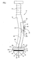
Figure 1 is a diagrammatic elevational view of one embodiment of a surgical introducing tool for an acetabular cup, in accordance with the second aspect of the invention, and having a first embodiment of a head in accordance with the first aspect of the invention; -
Figure 2 is an enlarged view of the head shown inFigure 1 , and an acetabular cup; -
Figure 3 is a scrap pictorial view showing exaggerated relative angular displacement between the polar axis of the head and the polar axis of the cup, when engaged; -
Figure 4 is a diagrammatic plan view from above of a second embodiment of a head, in accordance with the first aspect of the invention; -
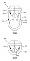
Figure 5 is a diagrammatic elevational view of a third embodiment of a head, in accordance with the first aspect of the invention; -
Figure 6 is a diagrammatic plan view from below of the head shown inFigure 5 ; -
Figure 7 is a diagrammatic elevational view of a fourth embodiment of a head, in accordance with the first aspect of the invention, shown being offered towards an embodiment of an acetabular cup, in accordance with the third aspect of the invention; -
Figure 8 is a view similar to that shown inFigure 7 with the head and acetabular cup engaged; -
Figure 9 is a diagrammatic elevational view of a fifth embodiment of a head, in accordance with the first aspect of the invention, shown being offered towards another embodiment of an acetabular cup, in accordance with the third aspect of the invention; -
Figure 10 is a view similar to that shown inFigure 9 with the head and acetabular cup engaged; -
Figure 11 is a diagrammatic elevational view of a sixth embodiment of a head, in accordance with the first aspect of the invention, shown being offered towards a further embodiment of an acetabular cup, in accordance with the third aspect of the invention; -
Figure 12 is a view similar to that shown inFigure 11 with the head and acetabular cup engaged; -
Figure 13 is a diagrammatic elevational view of a seventh embodiment of a head, in accordance with the first aspect of the invention, shown being offered towards an embodiment of an acetabular cup, in accordance with the third aspect of the invention; and -
Figure 14 is a view similar to that shown inFigure 13 with the head and acetabular cup engaged. - Referring firstly to
Figures 1 to 3 , there is shown a surgical introducingtool 10 which comprises ashaft 12 having ahandle 14 at one end and ahead 16 at the other end. - The
shaft 12, in this case, is non-rectilinear, being cranked to promote simplified access to a patient's acetabulum during use, particularly during minimal access surgery. However, theshaft 12 may be rectilinear. - The
head 16 includes abase plate 18,cup holding element 20 provided centrally on onemajor surface 18a of thebase plate 18, and a plurality of retainingelements 22. - The
cup holding element 20 is dimensioned to be a complementary or substantially complementary fit with an articulatinginner surface 24 of a knownacetabular cup 26, as can be understood fromFigure 2 . Ahead air passage 28 passes centrally through thebase plate 18, from the othermajor surface 18b, into thecup holding element 20. Thehead air passage 28, in thecup holding element 20, branches into threesub-passages 30 which open out on thesurface 20a of thecup holding element 20, at positions which are spaced from each other and which are generally remote from thebase plate 18. - The
cup holding element 20 also includes an O-ring seal 32 which extends around thecup holding element 20 at a position adjacent to the equatorial diameter of thecup 26. The O-ring seal 32 is thus located between thebase plate 18 andopenings 34 of theair sub-passages 30. - The
base plate 18 is dimensioned to overlap thecup holding element 20, thereby providing aflange 36 which extends around thecup holding element 20. The retainingelements 22 project from theflange 36, in spaced relationship to both thecup holding element 20 and each other. In this embodiment, threeretaining elements 22 are provided (only two being shown inFigures 1 and2 ), and are spaced equiangularly around thecup holding element 20. - The
retaining elements 22 project from theflange 36 in parallel with each other, and extend arcuately along the surface of theflange 36. - The
head 16 is screwthreadingly engagable, or otherwise modularly connectable, at thebase plate 18 with the end of theshaft 12 opposite thehandle 14. This allows preoperative and intra-operative changing of thehead 16 to one of different dimensions, for example when a different size of acetabular cup is required. However, the head may be permanently connected to the shaft. - The
shaft 12 includes aninternal air passage 40 which extends partway along the longitudinal extent of theshaft 12. Theshaft air passage 40 opens out at theend 42 of theshaft 12 opposite thehandle 14, and exits through aside 44 of theshaft 12 partway between the ends.Opening 46 of theshaft air passage 40 in theend 42 of theshaft 12 is positioned to align with opening 48 of thehead air passage 28 on thebase plate 18 of thehead 16. One or more seals (not shown) are provided which, when thehead 16 is engaged with theshaft 12, enables the head- and shaft-air passages tool 10. - The exit of the
shaft air passage 40 through theside 44 of theshaft 12 is via anipple connector 50 integrally formed on theshaft 12. Thenipple connector 50 enables connection of a suction line from remote air suction device (not shown). - The
shaft 12 also includes avent arrangement 52 for theshaft air passage 40. In this embodiment, thevent arrangement 52 comprises abranch passage 54 which leads from theshaft air passage 40 and opens out on theside 44 of theshaft 12, and an air-tight cap 56 or stop which covers anopening 58 on theshaft 12 to thebranch passage 54. The air-tight cap 56 is provided on apivotable lever 60 which can be operated via a user's thumb, for example. Thelever 60 is urged, typically by aspring 62, to assume a condition whereby the air-tight cap 56 normally seals the opening 58 to thebranch passage 54. - In use, and once the
head 16 is attached to theshaft 12, anacetabular cup 26 of suitable size is urged onto thecup holding element 20 and retainingelements 22 untilrim 66 abuts thebase plate 18. Thecup holding element 20 is dimensioned so that the O-ring seal 32 forms a fluid-tight interference fit on the articulatinginner surface 24 of theacetabular cup 26, and theretaining elements 22 are received as close or tolerance fits in respective openings orslots 64 in therim 66 of theacetabular cup 26. SeeFigure 2 . - An air line of an air suction device, which is usually available in theatre, is connected to the
nipple connector 50 and a vacuum is generated in the space between the articulatinginner surface 24 of theacetabular cup 26, thecup holding element 20, and the O-ring seal 32. Theacetabular cup 26 is thus securely held by the introducingtool 10. - The
acetabular cup 26 is introduced into the patient's body and positioned by impaction in the acetabulum. Once located, the surgeon can move thehandle 14 of thetool 10 in a reciprocating manner, in other words angularly displace the longitudinal axis of the tool, to position thecup 26 at the optimum angle. During this tilting movement, and since theacetabular cup 26 will now be held securely in the patient's acetabulum, slight relative angular displacement of polar axis P1 of thehead 16 and polar axis P2 of thecup 26 occurs. This results in slight separation or tilting of thehead 16 /base plate 18 from thecup 26. Theretaining elements 22 of thehead 16 consequently move in the openings orslots 64 in therim 66 of theacetabular cup 26. SeeFigure 3 . Each retainingelement 22, when titled due to the slight separation, will tend to bind on theinterior surfaces 68 of itsrespective rim slot 64, thus preventing excessive movement which would otherwise cause the fluid-tight seal generated by the O-ring seal 32 to break. Breakage of the fluid-tight seal causes a loss of vacuum and theacetabular cup 26 to be no longer securely gripped by thetool 10. - Once the surgeon is satisfied that the
acetabular cup 26 is securely located in the patient's acetabulum, thepivotable lever 60 on theshaft 12 is operated to lift the air-tight cap 56 and release the vacuum between thecup holding element 20 and the articulatinginner surface 24 of thecup 26. Thetool 10 can then be easily removed from thecup 26. - Obviously, the closer the tolerance of the fit between the retaining
elements 22 and therespective slots 64 in therim 66 of theacetabular cup 26, the less relative movement impartable therebetween, and the less relative angular displacement between the longitudinal axis of thetool 10 / polar axis P1 of thehead 16 and the polar axis P2 of thecup 26. -
Figure 4 shows a second embodiment of ahead 116 of the present invention. Similar references refer to similar parts, and further detailed description is omitted. - The
head 116 includes abase plate 118,cup holding element 120, and retainingelements 122, as in the first embodiment. Thebase plate 118, however, is non-circular, having equi-angularly spaced radially inwardly projectingrecesses 170 around the circumference. The number ofrecesses 170 corresponds to the number of retainingelements 122. In this case, threerecesses 170 are provided, which produces threeflanges 136 from which the retainingelements 122 extend. - The
cup holding element 120 is not correspondingly recessed, due to an interference equatorial or substantially equatorial fit being required between an O-ring seal 132 of thecup holding element 120 and an articulatinginner surface 124 of anacetabular cup 126. - The
recesses 170 in thebase plate 118 allows a user of atool 110 to see at least arim 166 of theacetabular cup 126. This is particularly beneficial during introduction and location of thecup 126 into a patient's acetabulum. -
Figures 5 and 6 show a third embodiment of ahead 216 of the present invention. Similar references refer to similar parts, and further detailed description is omitted. - In this embodiment, only a
single retaining element 222 is provided on aflange 236 ofhead 216. The retainingelement 222 is spaced radially outwards from acup holding element 220, and extends continuously in a circumferential direction to surround thecup holding element 220. - An acetabular cup (not shown) has a complementarily or substantially complementarily shaped continuous opening, being a slot or channel, formed in a rim of the cup, a continuous inner shoulder formed adjacent to the rim, or a continuous outer shoulder formed adjacent to the rim, depending on the spacing of the retaining
element 222 from thecup holding element 220. - In a modification, the retaining
element 222 could be a continuous opening, in other words a slot or channel, formed inflange 236 of thehead 216, and the acetabular cup therefore has a complementarily or substantially complementarily shaped projection positioned as described above. - In a further modification, two radially spaced concentric continuous retaining elements could be utilised. Complementarily or substantially complementarily shaped formations, being openings or projections, adapted to accept the retaining elements are therefore provided on the acetabular cup.
-
Figures 7 and 8 show a fourth embodiment of ahead 316 and an embodiment of anacetabular cup 326. Similar references refer to similar parts, and further detailed description is omitted. - In this embodiment, the
acetabular cup 326 includes one or more radiallyinner shoulders 372 adjacent torim 366. In use, one ormore retaining elements 322 is/are suitably spaced fromcup holding element 320 to closely fit the or eachshoulder 372. -
Figures 9 and 10 show a fifth embodiment of ahead 416 and another embodiment of anacetabular cup 426. Similar references refer to similar parts, and further detailed description is omitted. - In this embodiment, the
acetabular cup 426 includes one or more radiallyouter shoulders 474 adjacent torim 466. In use, one ormore retaining elements 422 is/are suitably spaced fromcup holding element 420 to closely fit the or eachouter shoulder 474. - In the fourth and fifth embodiments, it is envisaged that the acetabular cup can, additionally or alternatively, include one or more projections at or adjacent to the inner edge of the rim or the outer edge of the rim, and the or each respective retaining element of the head would therefore be an opening.
-
Figures 11 and 12 show a sixth embodiment of ahead 516, and another embodiment of anacetabular cup 526. Similar references refer to similar parts, and further detailed description is omitted. - The
acetabular cup 526 includes radially inner andouter shoulders rim 566. In use, retainingelements cup holding element 520 to closely fit theshoulders element 522a is spaced radially outwardly relative to the retainingelement 522b. - Similarly to the earlier embodiments, in a modification, one or more projections could, additionally or alternatively, be included at or adjacent to inner and outer edges of the rim of the acetabular cup, and the respective retaining elements of the head would therefore be openings.
-
Figures 13 and 14 show a seventh embodiment of ahead 616. Similar references refer to similar parts, and further detailed description is omitted. - In this embodiment, one or
more retaining elements 622 is/are integrally formed withcup holding element 620 and extend fromflange 636.Acetabular cup 626 includes one or more corresponding radiallyinner shoulders 672 adjacent torim 666. In use, the or each retainingelement 622 radially projects fromcup holding element 620 to closely fit the or eachinner shoulder 672. - It is envisaged that, in a modification to this embodiment, one or more of the retaining elements could be spaced from the flange of the head.
- Except in the case of a continuous retaining element, the retaining elements described above also prevent relative rotational displacement of the head and the cup.
- Any suitable number of retaining elements, and therefore corresponding recesses, can be provided. Thus, only a single retaining element may be required.
- Although the retaining elements are described as being tongues, the retaining elements can be pins or any other suitably shaped projection. The or each opening, which includes a shoulder and a recess, when in the acetabular cup may be a slot, channel, or any close- or tolerance- fitting complementarily shaped opening.
- As mentioned, it is possible that the rim of the acetabular cup can include one or more projections, instead of, or additionally to, the openings or slots. In this case, the retaining elements will be, or include, openings or slots formed in the flange or flanges of the base plate. These corresponding openings or slots will be dimensioned to closely fit the or each projection on the cup.
- The retaining element or elements of the head have a close or tolerance fit with the or each corresponding formation on or adjacent to the rim of the cup, in at least a radial direction of the cup holding element.
- The cup holding element described above can be any shape providing an interference fit is provided to enable formation of the vacuum seal by the O-ring seal. Regardless of shape, the cup holding element will still inherently have a polar axis.
- Although three air sub-passages are suggested in the cup holding element, any suitable number of passages, including a single sub-passage, can be utilised.
- Any suitable vent arrangement can be provided.
- It is thus possible to provide a head for a surgical introducing tool that more securely holds an acetabular cup during insertion. It is also possible to provide a head for a surgical introducing tool which prevents or limits relative angular displacement of the longitudinal axis of the tool and the polar axis of the acetabular cup.
Claims (20)
- A head for a surgical introducing tool (10;110), the head (16; 116;216;316,416-,516;616) comprising:a cup holding element (20;120;220;320;420;520;620) for releasably holding an acetabular cup (26;126;326;426;526;626), the holding element (20;120;220;320;420;520;620) including a seal (32;132) and an air passage (28) by which the acetabular cup (26; 126;326;426;526;626) can be held to the head (16;116;216;316;416;516;616) by vacuum; anda retaining element (22;122;222;322;422;522;622) for preventing undesirable release of the acetabular cup (26;126;326;426;526;626) from the holding element (20;120;220;320;420;520;620), the retaining element (22;122;222;322;422;522;622) being positioned radially outwardly relative to the holding element (20;120;220;320;420;520;620), characterised in that the retaining element (22,122,222,322,422,522,622) is configured to be received in an opening in or adjacent to the rim of the acetabular cup or to receive a projection on or adjacent to the rim of the acetabular cup,so that, in use, relative angular displacement of polar axes (P1, P2) of the head (16;116;216;316;416;516;616) and the acetabular cup (26;126;326;426;526;626) is prevented or limited by the retaining element (22;122;222;322;422;522,622) while the cup (26,126;326;426,526;626) is held by the holding element (20;120;220;320;420;520;620), so as to prevent the cup (26;126;326;426;526;626) from being accidentally released from the holding element (20;120;220;320;420;520;620).
- A head as claimed in claim 1, wherein the head (16;116;216;316;416;516;616) includes a flange (36;136;236;636) on or in which the retaining element (22;122;222;322;422;522;622) is positioned in spaced relationship to the holding element (20;120;220;320;420;520;620).
- A head as claimed in claim 1, wherein the head (16;116;216;316;416;516;616) includes a flange (36;136;236;636) from which the retaining element (22;122;222;322;422;522;622) extends, and the retaining element (22;122;222;322;422;522;622) is integrally formed with the holding element (20; 120;220;320;420;520;620).
- A head as claimed in claim 2 or claim 3, wherein the flange (36;636) surrounds the holding element (20;320;420;520;620), and a plurality of said retaining elements (22;322;422;522;622) are positioned on or in the flange (36;636).
- A head as claimed in claim 2 or claim 3, wherein the flange (236) surrounds the holding element (220), and a single continuous retaining element (222) is positioned on or in the flange (236).
- A head as claimed in claim 2 or claim 3, wherein a plurality of flanges (136) are provided angularly spaced around the holding element (120), a said retaining element (122) being positioned on or in each flange (136).
- A head as claimed in any one of the preceding claims, wherein a further retaining element (522a) is positioned radially outwardly relative to the first said retaining element (522b).
- A head as claimed in any one of the preceding claims, wherein the head includes one or more recesses which project radially inwards.
- A head as claimed in any one of the preceding claims, wherein the holding element (20;120;220;320;420;520;620) is dimensioned to be an interference fit in at least a portion of the space defined by the articulating inner surface (24;124;224) of the acetabular cup (26;126;326;426;526;626).
- A head as claimed in any one of the preceding claims, wherein the, each or at least one retaining element (22;122;222;322;422;522;622) is a projection or an opening.
- A surgical introducing tool (10;110) for an acetabular cup (26;126;326;426;526;626), the tool (10;110) comprising a shaft (12) having a handle (14) at one end, and a head (16;116;216;316;416;516;616) as claimed in any one of the preceding claims at the other end of the shaft.
- A surgical introducing tool as claimed in claim 11, wherein the head (16;116;216;316;416;516;616) is releasably engaged with the said other end of the shaft (12).
- A surgical introducing tool as claimed in claim 11 or claim 12, wherein an air passage (40) is formed in the shaft (12), one end of the air passage (40) fluidly communicating with the air passage (28) in the head (16; 116;216;316;416;516;616), and the other end being connectable to an air suction device.
- A surgical introducing tool as claimed in claim 13, further comprising a vent arrangement (52) for admitting air to the shaft air passage (40).
- An acetabular cup (26;126;326;426;526;626) in combination with a head (16;116;216;316;416;516;616) for a surgical introducing tool as claimed in any one of claims 1 to 10, the cup having one or more formations (64) adapted to accept the or each said retaining element (22;122;222;322;422;522;622) of the head (16;116;216;316;416;516;616), wherein the or each formation (64) is not an elongate slot having closed ends and being formed in a rim of the cup.
- An acetabular cup in combination with a head for a surgical introducing tool as claimed in claim 15, wherein the or each formation (64) is an opening formed in a rim (66;166) of the acetabular cup (26;126), a radially inner shoulder (372;572;672) formed adjacent to the rim (366;566;666) of the acetabular cup (326;526;626), and/or a radially outer shoulder (474;574) formed adjacent to the rim (466;566) of the acetabular cup (426;526).
- An acetabular cup in combination with a head for a surgical introducing tool as claimed in claim 16, wherein a plurality of rim openings, inner shoulders and in combination with a head for a surgical introducing tool or outer shoulders are provided.
- An acetabular cup in combination with a head for a surgical introducing tool as claimed in claim 16, wherein a single rim opening, inner shoulder and/or outer shoulder is provided.
- An acetabular cup in combination with a head for a surgical introducing tool as claimed in claim 18, wherein the single rim opening, inner shoulder, and/or outer shoulder is continuous.
- An acetabular cup in combination with a head for a surgical introducing tool as claimed in claim 15, wherein the, each or at least one formation is a projection formed on the rim of the acetabular cup, the projection being provided on or adjacent to an inner edge of the rim, on or adjacent to an outer edge of the rim, and/or partway between inner and outer edges of the rim.
Applications Claiming Priority (1)
| Application Number | Priority Date | Filing Date | Title |
|---|---|---|---|
| GB0504123A GB2423715A (en) | 2005-03-01 | 2005-03-01 | Surgical introducer |
Publications (2)
| Publication Number | Publication Date |
|---|---|
| EP1698306A1 EP1698306A1 (en) | 2006-09-06 |
| EP1698306B1 true EP1698306B1 (en) | 2008-02-20 |
Family
ID=34430370
Family Applications (1)
| Application Number | Title | Priority Date | Filing Date |
|---|---|---|---|
| EP05257767A Expired - Lifetime EP1698306B1 (en) | 2005-03-01 | 2005-12-16 | Surgical introducer |
Country Status (6)
| Country | Link |
|---|---|
| US (1) | US20060229630A1 (en) |
| EP (1) | EP1698306B1 (en) |
| AT (1) | ATE386486T1 (en) |
| DE (1) | DE602005004890T2 (en) |
| ES (1) | ES2300955T3 (en) |
| GB (1) | GB2423715A (en) |
Families Citing this family (17)
| Publication number | Priority date | Publication date | Assignee | Title |
|---|---|---|---|---|
| GB0302409D0 (en) * | 2003-02-03 | 2003-03-05 | Depuy Int Ltd | A cup component of an orthopaedics joint prosthesis |
| FR2876278B1 (en) | 2004-10-13 | 2007-10-26 | Thomas Gradel | COTYL APPLICATION INSTRUMENTS |
| US8425526B2 (en) * | 2006-10-17 | 2013-04-23 | Smith & Nephew, Inc. | Adjustable impactor |
| FR2916960B1 (en) * | 2007-06-11 | 2010-09-03 | Herve Arnould | CUPLE FOR COTYLOID IMPLANT |
| US8702805B2 (en) * | 2008-07-21 | 2014-04-22 | Harutaro Trabish | Acetabulum surgical resurfacing aid |
| US9613794B2 (en) * | 2008-07-30 | 2017-04-04 | John Becker | Extending light bulb replacing tool |
| GB2473610A (en) * | 2009-09-16 | 2011-03-23 | Corin Ltd | Surgical introducing tool kit |
| EP2596763B1 (en) | 2011-11-25 | 2014-01-08 | Waldemar Link GmbH & Co. KG | Tool for setting or removing joint components of artificial joint sockets, in particular for hip joint prostheses |
| US20140094821A1 (en) * | 2012-09-28 | 2014-04-03 | Depuy Products, Inc. | Impactor for Securing an Implant to a Bone Surface |
| FR3004339B1 (en) * | 2013-04-12 | 2015-05-15 | Groupe Lepine | METHOD OF PACKAGING AND STERILE PACKAGING OF A COTYLOID CUP OF HIP PROSTHESIS |
| GB201317287D0 (en) | 2013-09-30 | 2013-11-13 | Depuy Ireland Ltd | An instrument for positioning a cup component of an orthopaedic joint prosthesis |
| GB2529203B (en) * | 2014-08-13 | 2016-09-28 | James Wallace Mcminn Derek | Acetabular cup prosthesis |
| FR3026293B1 (en) * | 2014-09-25 | 2016-10-21 | Groupe Lepine | ASSEMBLY COMPRISING A CUP-SHAPED IMPLANT AND A PREHIBITOR OF THE IMPLANT, AND METHOD FOR PRODUCING THE SAME |
| ITUB20152433A1 (en) * | 2015-07-23 | 2017-01-23 | Amil S R L | DEVICE AND METHOD OF SOCKET AND POSITIONING OF PROSTHETIC PARTS |
| US10588756B2 (en) | 2017-03-31 | 2020-03-17 | DePuy Synthes Products, Inc. | System and method for implanting an acetabular prosthetic component |
| US10596011B2 (en) | 2018-01-31 | 2020-03-24 | Depuy Ireland Unlimited Company | Orthopaedic surgical instrument and method for positioning an acetabular prosthetic component |
| DE102022107977A1 (en) | 2022-04-04 | 2023-10-05 | Fraunhofer-Gesellschaft zur Förderung der angewandten Forschung eingetragener Verein | System for joining joint implant components |
Family Cites Families (10)
| Publication number | Priority date | Publication date | Assignee | Title |
|---|---|---|---|---|
| US3859992A (en) * | 1973-06-06 | 1975-01-14 | Harlan C Amstutz | Vacuum-operated acetabular cup holder and positioner |
| US5171243A (en) * | 1991-02-13 | 1992-12-15 | Pfizer Hospital Products Group, Inc. | Acetabular cup positioning insert |
| DE19722923B4 (en) * | 1997-02-06 | 2008-04-10 | Ceramtec Ag Innovative Ceramic Engineering | Tool for inserting a ceramic insert shell in a metallic outer shell of a two-part socket prosthesis |
| DE29823658U1 (en) * | 1998-06-22 | 1999-09-30 | ESKA Implants GmbH & Co., 23556 Lübeck | Instrument for inserting an inlay and inserting it into the base of a pelvic socket of an artificial hip joint |
| US6152930A (en) * | 1998-10-28 | 2000-11-28 | Depuy Orthopaedics, Inc. | Acetabular cup extraction system |
| FR2797180B1 (en) * | 1999-07-21 | 2004-04-02 | Groupe Lepine | ASSEMBLY COMPRISING AT LEAST ONE COTYLOID CUP AND AN ANCILLARY TOOL FOR THE PLACEMENT OF THIS CUP |
| GB9918884D0 (en) * | 1999-08-10 | 1999-10-13 | Novarticulate Bv | Method and apparatus for delivering cement to bones |
| FR2809305B1 (en) * | 2000-05-26 | 2003-04-04 | Amplitude | ANCILLARY INSTRUMENT FOR LAYING A COTYLOIDIAN CUP FOR A HIP JOINT PROSTHESIS |
| US20050137603A1 (en) * | 2003-11-12 | 2005-06-23 | Kevin Belew | Acetabular cup positioning instrument |
| US7931656B2 (en) * | 2004-01-05 | 2011-04-26 | Paramount Medical Instruments, L.L.C. | Acetabular shell impactor |
-
2005
- 2005-03-01 GB GB0504123A patent/GB2423715A/en active Pending
- 2005-12-16 ES ES05257767T patent/ES2300955T3/en not_active Expired - Lifetime
- 2005-12-16 EP EP05257767A patent/EP1698306B1/en not_active Expired - Lifetime
- 2005-12-16 DE DE602005004890T patent/DE602005004890T2/en not_active Expired - Lifetime
- 2005-12-16 AT AT05257767T patent/ATE386486T1/en not_active IP Right Cessation
-
2006
- 2006-01-13 US US11/331,000 patent/US20060229630A1/en not_active Abandoned
Also Published As
| Publication number | Publication date |
|---|---|
| DE602005004890T2 (en) | 2009-02-12 |
| US20060229630A1 (en) | 2006-10-12 |
| DE602005004890D1 (en) | 2008-04-03 |
| ES2300955T3 (en) | 2008-06-16 |
| ATE386486T1 (en) | 2008-03-15 |
| GB2423715A (en) | 2006-09-06 |
| EP1698306A1 (en) | 2006-09-06 |
| GB0504123D0 (en) | 2005-04-06 |
Similar Documents
| Publication | Publication Date | Title |
|---|---|---|
| EP1698306A1 (en) | Surgical introducer | |
| EP2033599B1 (en) | Modular bone implant, tools and method | |
| US7993348B2 (en) | Curved acetabular positioner, impactor and reamer handle | |
| US4795469A (en) | Threaded acetabular cup and method | |
| US7025721B2 (en) | Endoscope channel cap | |
| US8500744B2 (en) | Cap and activation tool | |
| ES2235241T3 (en) | COUPLINGS FOR MEDICAL CANULAS. | |
| ES2384073T3 (en) | Improvements in or related to tube couplings | |
| EP2198808B1 (en) | Liner for a joint prosthesis component | |
| US9050110B2 (en) | Medical device | |
| US8075551B2 (en) | Surgical coupling device | |
| US20100137870A1 (en) | Acetabular liner inserter guide | |
| JP2024504835A (en) | Trial neck and method | |
| US6512348B1 (en) | Battery aligner insertion apparatus and method | |
| US12345352B2 (en) | Fluid transfer device and method of use for same | |
| EP3811879A1 (en) | Milling head for a milling tool for prosthetic surgery operations and corresponding milling tool | |
| EP1661521B1 (en) | Gripping member for biomedical needle | |
| US20180325696A1 (en) | Holder For An Acetabular Cup Implant | |
| GB2473610A (en) | Surgical introducing tool kit | |
| GB2347864A (en) | Attachment for an acetabular cup in a dysplastic acetabulum | |
| EP3485821A1 (en) | Orthopaedic reamer system | |
| US20240269587A1 (en) | Closure element for drainage opening of filter system, filter housing part of filter system, filter element, and filter system | |
| CN115916117A (en) | Improved retainer for acetabular cup implants | |
| AU2004218735B2 (en) | Modular bone implant, tools, and method |
Legal Events
| Date | Code | Title | Description |
|---|---|---|---|
| PUAI | Public reference made under article 153(3) epc to a published international application that has entered the european phase |
Free format text: ORIGINAL CODE: 0009012 |
|
| AK | Designated contracting states |
Kind code of ref document: A1 Designated state(s): AT BE BG CH CY CZ DE DK EE ES FI FR GB GR HU IE IS IT LI LT LU LV MC NL PL PT RO SE SI SK TR |
|
| AX | Request for extension of the european patent |
Extension state: AL BA HR MK YU |
|
| 17P | Request for examination filed |
Effective date: 20070125 |
|
| 17Q | First examination report despatched |
Effective date: 20070223 |
|
| AKX | Designation fees paid |
Designated state(s): AT BE BG CH CY CZ DE DK EE ES FI FR GB GR HU IE IS IT LI LT LU LV MC NL PL PT RO SE SI SK TR |
|
| GRAP | Despatch of communication of intention to grant a patent |
Free format text: ORIGINAL CODE: EPIDOSNIGR1 |
|
| GRAS | Grant fee paid |
Free format text: ORIGINAL CODE: EPIDOSNIGR3 |
|
| GRAA | (expected) grant |
Free format text: ORIGINAL CODE: 0009210 |
|
| AK | Designated contracting states |
Kind code of ref document: B1 Designated state(s): AT BE BG CH CY CZ DE DK EE ES FI FR GB GR HU IE IS IT LI LT LU LV MC NL PL PT RO SE SI SK TR |
|
| REG | Reference to a national code |
Ref country code: GB Ref legal event code: FG4D |
|
| REG | Reference to a national code |
Ref country code: CH Ref legal event code: EP |
|
| REG | Reference to a national code |
Ref country code: IE Ref legal event code: FG4D |
|
| REF | Corresponds to: |
Ref document number: 602005004890 Country of ref document: DE Date of ref document: 20080403 Kind code of ref document: P |
|
| REG | Reference to a national code |
Ref country code: ES Ref legal event code: FG2A Ref document number: 2300955 Country of ref document: ES Kind code of ref document: T3 |
|
| PG25 | Lapsed in a contracting state [announced via postgrant information from national office to epo] |
Ref country code: IS Free format text: LAPSE BECAUSE OF FAILURE TO SUBMIT A TRANSLATION OF THE DESCRIPTION OR TO PAY THE FEE WITHIN THE PRESCRIBED TIME-LIMIT Effective date: 20080620 Ref country code: FI Free format text: LAPSE BECAUSE OF FAILURE TO SUBMIT A TRANSLATION OF THE DESCRIPTION OR TO PAY THE FEE WITHIN THE PRESCRIBED TIME-LIMIT Effective date: 20080220 |
|
| NLV1 | Nl: lapsed or annulled due to failure to fulfill the requirements of art. 29p and 29m of the patents act | ||
| PG25 | Lapsed in a contracting state [announced via postgrant information from national office to epo] |
Ref country code: AT Free format text: LAPSE BECAUSE OF FAILURE TO SUBMIT A TRANSLATION OF THE DESCRIPTION OR TO PAY THE FEE WITHIN THE PRESCRIBED TIME-LIMIT Effective date: 20080220 |
|
| PG25 | Lapsed in a contracting state [announced via postgrant information from national office to epo] |
Ref country code: SI Free format text: LAPSE BECAUSE OF FAILURE TO SUBMIT A TRANSLATION OF THE DESCRIPTION OR TO PAY THE FEE WITHIN THE PRESCRIBED TIME-LIMIT Effective date: 20080220 Ref country code: LV Free format text: LAPSE BECAUSE OF FAILURE TO SUBMIT A TRANSLATION OF THE DESCRIPTION OR TO PAY THE FEE WITHIN THE PRESCRIBED TIME-LIMIT Effective date: 20080220 Ref country code: PL Free format text: LAPSE BECAUSE OF FAILURE TO SUBMIT A TRANSLATION OF THE DESCRIPTION OR TO PAY THE FEE WITHIN THE PRESCRIBED TIME-LIMIT Effective date: 20080220 Ref country code: BE Free format text: LAPSE BECAUSE OF FAILURE TO SUBMIT A TRANSLATION OF THE DESCRIPTION OR TO PAY THE FEE WITHIN THE PRESCRIBED TIME-LIMIT Effective date: 20080220 |
|
| ET | Fr: translation filed | ||
| PG25 | Lapsed in a contracting state [announced via postgrant information from national office to epo] |
Ref country code: SE Free format text: LAPSE BECAUSE OF FAILURE TO SUBMIT A TRANSLATION OF THE DESCRIPTION OR TO PAY THE FEE WITHIN THE PRESCRIBED TIME-LIMIT Effective date: 20080520 Ref country code: CZ Free format text: LAPSE BECAUSE OF FAILURE TO SUBMIT A TRANSLATION OF THE DESCRIPTION OR TO PAY THE FEE WITHIN THE PRESCRIBED TIME-LIMIT Effective date: 20080220 Ref country code: NL Free format text: LAPSE BECAUSE OF FAILURE TO SUBMIT A TRANSLATION OF THE DESCRIPTION OR TO PAY THE FEE WITHIN THE PRESCRIBED TIME-LIMIT Effective date: 20080220 Ref country code: PT Free format text: LAPSE BECAUSE OF FAILURE TO SUBMIT A TRANSLATION OF THE DESCRIPTION OR TO PAY THE FEE WITHIN THE PRESCRIBED TIME-LIMIT Effective date: 20080721 Ref country code: DK Free format text: LAPSE BECAUSE OF FAILURE TO SUBMIT A TRANSLATION OF THE DESCRIPTION OR TO PAY THE FEE WITHIN THE PRESCRIBED TIME-LIMIT Effective date: 20080220 Ref country code: SK Free format text: LAPSE BECAUSE OF FAILURE TO SUBMIT A TRANSLATION OF THE DESCRIPTION OR TO PAY THE FEE WITHIN THE PRESCRIBED TIME-LIMIT Effective date: 20080220 |
|
| PG25 | Lapsed in a contracting state [announced via postgrant information from national office to epo] |
Ref country code: RO Free format text: LAPSE BECAUSE OF FAILURE TO SUBMIT A TRANSLATION OF THE DESCRIPTION OR TO PAY THE FEE WITHIN THE PRESCRIBED TIME-LIMIT Effective date: 20080220 |
|
| PLBE | No opposition filed within time limit |
Free format text: ORIGINAL CODE: 0009261 |
|
| STAA | Information on the status of an ep patent application or granted ep patent |
Free format text: STATUS: NO OPPOSITION FILED WITHIN TIME LIMIT |
|
| 26N | No opposition filed |
Effective date: 20081121 |
|
| PG25 | Lapsed in a contracting state [announced via postgrant information from national office to epo] |
Ref country code: LT Free format text: LAPSE BECAUSE OF FAILURE TO SUBMIT A TRANSLATION OF THE DESCRIPTION OR TO PAY THE FEE WITHIN THE PRESCRIBED TIME-LIMIT Effective date: 20080220 |
|
| PG25 | Lapsed in a contracting state [announced via postgrant information from national office to epo] |
Ref country code: EE Free format text: LAPSE BECAUSE OF FAILURE TO SUBMIT A TRANSLATION OF THE DESCRIPTION OR TO PAY THE FEE WITHIN THE PRESCRIBED TIME-LIMIT Effective date: 20080220 Ref country code: BG Free format text: LAPSE BECAUSE OF FAILURE TO SUBMIT A TRANSLATION OF THE DESCRIPTION OR TO PAY THE FEE WITHIN THE PRESCRIBED TIME-LIMIT Effective date: 20080520 |
|
| PG25 | Lapsed in a contracting state [announced via postgrant information from national office to epo] |
Ref country code: MC Free format text: LAPSE BECAUSE OF NON-PAYMENT OF DUE FEES Effective date: 20081231 Ref country code: CY Free format text: LAPSE BECAUSE OF FAILURE TO SUBMIT A TRANSLATION OF THE DESCRIPTION OR TO PAY THE FEE WITHIN THE PRESCRIBED TIME-LIMIT Effective date: 20080220 |
|
| PGFP | Annual fee paid to national office [announced via postgrant information from national office to epo] |
Ref country code: ES Payment date: 20091222 Year of fee payment: 5 |
|
| PGFP | Annual fee paid to national office [announced via postgrant information from national office to epo] |
Ref country code: FR Payment date: 20100108 Year of fee payment: 5 Ref country code: IE Payment date: 20100222 Year of fee payment: 5 Ref country code: IT Payment date: 20091221 Year of fee payment: 5 |
|
| PGFP | Annual fee paid to national office [announced via postgrant information from national office to epo] |
Ref country code: DE Payment date: 20091222 Year of fee payment: 5 |
|
| PG25 | Lapsed in a contracting state [announced via postgrant information from national office to epo] |
Ref country code: LU Free format text: LAPSE BECAUSE OF NON-PAYMENT OF DUE FEES Effective date: 20081216 Ref country code: HU Free format text: LAPSE BECAUSE OF FAILURE TO SUBMIT A TRANSLATION OF THE DESCRIPTION OR TO PAY THE FEE WITHIN THE PRESCRIBED TIME-LIMIT Effective date: 20080821 |
|
| REG | Reference to a national code |
Ref country code: CH Ref legal event code: PL |
|
| PG25 | Lapsed in a contracting state [announced via postgrant information from national office to epo] |
Ref country code: TR Free format text: LAPSE BECAUSE OF FAILURE TO SUBMIT A TRANSLATION OF THE DESCRIPTION OR TO PAY THE FEE WITHIN THE PRESCRIBED TIME-LIMIT Effective date: 20080220 |
|
| PG25 | Lapsed in a contracting state [announced via postgrant information from national office to epo] |
Ref country code: LI Free format text: LAPSE BECAUSE OF NON-PAYMENT OF DUE FEES Effective date: 20091231 Ref country code: CH Free format text: LAPSE BECAUSE OF NON-PAYMENT OF DUE FEES Effective date: 20091231 Ref country code: GR Free format text: LAPSE BECAUSE OF FAILURE TO SUBMIT A TRANSLATION OF THE DESCRIPTION OR TO PAY THE FEE WITHIN THE PRESCRIBED TIME-LIMIT Effective date: 20080521 |
|
| PGFP | Annual fee paid to national office [announced via postgrant information from national office to epo] |
Ref country code: GB Payment date: 20101110 Year of fee payment: 6 |
|
| REG | Reference to a national code |
Ref country code: FR Ref legal event code: ST Effective date: 20110831 |
|
| PG25 | Lapsed in a contracting state [announced via postgrant information from national office to epo] |
Ref country code: IE Free format text: LAPSE BECAUSE OF NON-PAYMENT OF DUE FEES Effective date: 20101216 Ref country code: FR Free format text: LAPSE BECAUSE OF NON-PAYMENT OF DUE FEES Effective date: 20110103 |
|
| REG | Reference to a national code |
Ref country code: DE Ref legal event code: R119 Ref document number: 602005004890 Country of ref document: DE Effective date: 20110701 |
|
| PG25 | Lapsed in a contracting state [announced via postgrant information from national office to epo] |
Ref country code: DE Free format text: LAPSE BECAUSE OF NON-PAYMENT OF DUE FEES Effective date: 20110701 |
|
| PG25 | Lapsed in a contracting state [announced via postgrant information from national office to epo] |
Ref country code: IT Free format text: LAPSE BECAUSE OF NON-PAYMENT OF DUE FEES Effective date: 20101216 |
|
| REG | Reference to a national code |
Ref country code: ES Ref legal event code: FD2A Effective date: 20120206 |
|
| PG25 | Lapsed in a contracting state [announced via postgrant information from national office to epo] |
Ref country code: ES Free format text: LAPSE BECAUSE OF NON-PAYMENT OF DUE FEES Effective date: 20101217 |
|
| GBPC | Gb: european patent ceased through non-payment of renewal fee |
Effective date: 20111216 |
|
| PG25 | Lapsed in a contracting state [announced via postgrant information from national office to epo] |
Ref country code: GB Free format text: LAPSE BECAUSE OF NON-PAYMENT OF DUE FEES Effective date: 20111216 |