EP1697709B1 - Device and method for sensing and displaying convexo concave - Google Patents
Device and method for sensing and displaying convexo concave Download PDFInfo
- Publication number
- EP1697709B1 EP1697709B1 EP04808178A EP04808178A EP1697709B1 EP 1697709 B1 EP1697709 B1 EP 1697709B1 EP 04808178 A EP04808178 A EP 04808178A EP 04808178 A EP04808178 A EP 04808178A EP 1697709 B1 EP1697709 B1 EP 1697709B1
- Authority
- EP
- European Patent Office
- Prior art keywords
- convex
- concave surface
- surface curvature
- exhibiting
- sensing
- Prior art date
- Legal status (The legal status is an assumption and is not a legal conclusion. Google has not performed a legal analysis and makes no representation as to the accuracy of the status listed.)
- Ceased
Links
Images



Classifications
-
- G—PHYSICS
- G01—MEASURING; TESTING
- G01B—MEASURING LENGTH, THICKNESS OR SIMILAR LINEAR DIMENSIONS; MEASURING ANGLES; MEASURING AREAS; MEASURING IRREGULARITIES OF SURFACES OR CONTOURS
- G01B5/00—Measuring arrangements characterised by the use of mechanical techniques
-
- A—HUMAN NECESSITIES
- A61—MEDICAL OR VETERINARY SCIENCE; HYGIENE
- A61B—DIAGNOSIS; SURGERY; IDENTIFICATION
- A61B5/00—Measuring for diagnostic purposes; Identification of persons
- A61B5/0048—Detecting, measuring or recording by applying mechanical forces or stimuli
- A61B5/0053—Detecting, measuring or recording by applying mechanical forces or stimuli by applying pressure, e.g. compression, indentation, palpation, grasping, gauging
-
- A—HUMAN NECESSITIES
- A61—MEDICAL OR VETERINARY SCIENCE; HYGIENE
- A61B—DIAGNOSIS; SURGERY; IDENTIFICATION
- A61B5/00—Measuring for diagnostic purposes; Identification of persons
- A61B5/44—Detecting, measuring or recording for evaluating the integumentary system, e.g. skin, hair or nails
- A61B5/441—Skin evaluation, e.g. for skin disorder diagnosis
- A61B5/442—Evaluating skin mechanical properties, e.g. elasticity, hardness, texture, wrinkle assessment
-
- A—HUMAN NECESSITIES
- A61—MEDICAL OR VETERINARY SCIENCE; HYGIENE
- A61B—DIAGNOSIS; SURGERY; IDENTIFICATION
- A61B5/00—Measuring for diagnostic purposes; Identification of persons
- A61B5/68—Arrangements of detecting, measuring or recording means, e.g. sensors, in relation to patient
- A61B5/6801—Arrangements of detecting, measuring or recording means, e.g. sensors, in relation to patient specially adapted to be attached to or worn on the body surface
- A61B5/6802—Sensor mounted on worn items
- A61B5/6804—Garments; Clothes
- A61B5/6806—Gloves
-
- A—HUMAN NECESSITIES
- A61—MEDICAL OR VETERINARY SCIENCE; HYGIENE
- A61B—DIAGNOSIS; SURGERY; IDENTIFICATION
- A61B8/00—Diagnosis using ultrasonic, sonic or infrasonic waves
-
- A—HUMAN NECESSITIES
- A61—MEDICAL OR VETERINARY SCIENCE; HYGIENE
- A61B—DIAGNOSIS; SURGERY; IDENTIFICATION
- A61B2562/00—Details of sensors; Constructional details of sensor housings or probes; Accessories for sensors
- A61B2562/02—Details of sensors specially adapted for in-vivo measurements
-
- B—PERFORMING OPERATIONS; TRANSPORTING
- B33—ADDITIVE MANUFACTURING TECHNOLOGY
- B33Y—ADDITIVE MANUFACTURING, i.e. MANUFACTURING OF THREE-DIMENSIONAL [3D] OBJECTS BY ADDITIVE DEPOSITION, ADDITIVE AGGLOMERATION OR ADDITIVE LAYERING, e.g. BY 3D PRINTING, STEREOLITHOGRAPHY OR SELECTIVE LASER SINTERING
- B33Y80/00—Products made by additive manufacturing
Definitions
- the present invention relates to a convex or concave surface curvature amplifying device and a convex or concave surface curvature detecting method using it, to be used for detecting a convex or concave surface curvature of an object such as a surface of a steel plate.
- US 4, 657, 021 and US 4, 793, 354 disclose means for easily detecting or sensing the convex or concave surface curvature of the object.
- the detecting means is a touch enhancing pad comprised of two flexible sheets, and a small amount of lubricant oil sealed between the two sheets.
- the touch enhancing pad In using the touch enhancing pad, with one sheet being contacted and rested on a surface of a subject, the other sheet in contact with the finger is moved together with the finger. As a result, movement of the lubricant oil reduces influence of friction between the subj ect and the fingertip, whereby the convex or concave surface curvature of the object can be clearly detected by smooth moving of the finger-tip.
- This touch enhancing pad has been put into the market by the name of "BSE (Breast Self-Examination) Pad", and is approved by FDA as a self-examination assisting tool for the breast cancer. Generally, the tactile sensing of the finger may get dull on the condition that some intervening material is interposed between the surface of the object and the finger tip.
- This pad can, without using the complex mechatronics technique, detect the convex or concave surface curvature of the object clearly. However, it can hardly detect the small or fine convex or concave surface curvature, and is not practical as the tool to detect the convex or concave surface curvature of the object extensively. Further, though it has a simple construction that the lubricant oil is sealed between the two sheets, it has to be feared that the lubricant oil is leaked by the damage of the sheet.
- the technique for detecting the convex or concave surface curvature of the object has been required in many fields.
- the subject surface of the object
- the former type is not suitable for the extensive inspection of the object.
- the latter type suffers from dispersion of the detected result due to luster and blot existing on the surface of the object.
- the both types require expensive apparatus and much time for setting. Therefore, in the strain inspection of a steel plate of manufacturing process in practice, for example, vehicle manufacturing process, skilled workers detect the convex or concave surface curvature by hand.
- the transducexer comprises a helical coil from two interposed electrical conductors which are electrically isolated from each other.
- the coil is bonded along one side over its entire length to a flexible non-extensible support surface, whereby flexion of the support surface causes a change in the length of the coil between said one side, which retains its original length and a side opposite to said one side.
- This relative change in length between opposite sides causes a change in capacitance between the two conductors.
- a tactile transducer to provide a tactile display or serve as a tactile input sensor.
- Paired contactors having contactor tips separated by a gap are connected to an actuator or sensor. Variations in the gap distance can create a tactile experience through skin stretch, or provide tactile input in sensor made.
- US 6, 179, 790 B1 there is known a method for detecting breast cancer wherein a sensor array is pressed against tissue. It is described to translate the sensor array over the tissue to allow the user to increase breast area coverage with less exam time.
- the object of the invention is to provide a convex or concave surface curvature amplifying device which has a simple construction and can exhibit a convex or concave surface curvature by amplifying a sense of a convex or concave surface curvature of the object and to a convex or concave surface curvature detecting method which detects the convex or concave surface curvature of the object by using the convex or concave surface curvature amplifying device.
- the object of the invention is attained by a convex or concave surface curvature amplifying device according to claim 1 or a convex or concave surface curvature detecting method according to claim 9. Further developments of the invention are characterized in the dependent claims.
- a convex or concave surface curvature amplifying device for exhibiting a convex or concave surface curvature by amplifying a sense of a convex or concave surface curvature of an object of the present invention comprises a sensing member comprising a flexible sheet able to contact with the surface of the object and to deform along the surface of the object; and an exhibiting member (for transducing a surface curvature) that is formed on a surface of the flexible sheet and has a deformation resistance smaller than that of the flexible sheet in at least one of directions orthogonal to a direction of thickness of the flexible sheet.
- the convex or concave surface curvature amplifying device is able to exhibit or transduce the convex or concave surface curvature by that the exhibiting member exactly amplifies the sense of the convex or concave surface curvature of the obj ect, which is sensed by the sheet member.
- the convex or concave surface curvature amplifying device has a simple configuration comprising the sensing member and exhibiting member so that breakdown or breakage hardly happens and the cost is low.
- a convex or concave surface curvature amplifying device of the present invention senses a convex or concave surface curvature of an object to exhibit or transduce it with amplification.
- a sheet having a constant composition and a constant thickness is contacted with a surface of an object at one surface (a lower surface, for example), the sheet deforms or deflects along the convex or concave surface curvature of the object. In the deflection, expansion and contraction occur in an upper and a lower surfaces of the sheet.
- an intermediate or neutral surface M not expanding and contracting exists in the sheet 110.
- the upper surface of the sheet goes away from the intermediate surface M, that is as thickness of the sheet becomes larger, expansion/contraction amount of the sheet upper surface becomes larger.
- thickness of the sheet is desirably increased to make deformed amount of the sheet upper surface larger.
- the convex or concave surface curvature amplifying device of the present invention is comprised of a sensing member, and an exhibiting member.
- the sensing member is comprising a flexible sheet to be able to contact with the surface of the object and to deform along the surface of the object.
- the exhibiting member is formed on a surface of the flexible sheet. Deformation resistance of the exhibiting member is smaller than that of the flexible sheet in at least one of directions orthogonal to a direction of thickness (extended or spread direction) of the flexible sheet.
- the sensing member constructing the convex or concave surface curvature amplifying device When the sensing member constructing the convex or concave surface curvature amplifying device is mechanically contacted with the object at one surface (hereinafter, briefly called “lower surface of the sensing member”), it deforms following to the object surface due to flexibility thereof.
- the exhibiting member on the other surface of the sensing member hereinafter briefly called “upper surface of the sensing member” also deforms.
- Deformation resistance of the exhibiting member in at least one direction in the spread direction is smaller than that of the sensing member in the same direction.
- the flexibility of the sensing member is not degraded even if the thickness of the convex or concave surface curvature amplifying device is large as a whole.
- the exhibiting member can effectively exhibit the convex or concave surface curvature of the object sensed with amplification.
- a convex or concave surface curvature amplifying device is shown schematically in the two-dimensional space. It is comprised of a sensing member 111, and an exhibiting member 121 formed on the sensing member 111.
- a deformation resistance of the exhibiting member 121 in the spread direction of the sensing member 111 is small.
- the exhibiting member 121 includes plural pin-like protrusions 126 extending in the thickness direction (up-down direction in Figure 2 ), and separated equidistantly in the spread direction (lateral direction in Figure 2 ). Namely, the deformation resistance of the exhibiting member 121 in the lateral direction is smaller than that of the sensing member 111 in the same direction.
- the convex or concave surface curvature amplifying device put on a flat (standard) surface is shown by a dotted line, while that put on an inclined surface (inclined angle: ⁇ ) is shown by a solid line.
- the convex or concave surface curvature amplifying device is put on the inclined surface, the protrusions 126 of the exhibiting member 121 deform or incline in a normal direction and a tangential direction of the standard surface.
- the neutral surface M exists in the sensing member 111 and thickness of the sensing member 111 is extremely small, deformation or inclination of the protrusions 126 in the tangential direction is proportional to product of the inclined angle ⁇ of the inclined surface Ob, and thickness T of the convex or concave surface curvature amplifying device.
- thickness T is sum of thickness of the sensing member 111 and length of the protrusions 126. Inclination of the protrusions 126 in the normal direction is equal to height H of the inclined surface Ob.
- the convex or concave surface curvature amplifying device of the present invention comprised of the sensing member and the exhibiting member, the thicker or longer exhibiting member can amplify and exhibit convex or concave surface curvature of the object sensed by the sensing member accurately.
- convex or concave surface curvature amplifying device deformation resistance of the exhibiting member in at least one direction in the spread direction is smaller than that of the sensing member in the same direction.
- the convex or concave surface curvature amplifying device convenient to effectively senses convex or concave surface curvature of the object , amplifies and exhibits the sensed convex or concave surface curvature can be obtained.
- ratio between thickness of the sensing member and length of the exhibiting member can range from 1:10 to 1:100.
- the sensing member has flexibility to deform following (tracing) along the object surface. This is because the lower surface of the sensing member is contacted (touched) with the object surface, or it is pressed onto the object surface.
- the elastic modulus of the sensing member ranges from 500 to 3000 MPa, 1500 to 2500 MPa is more preferable.
- the sensing member can be made of resin such as polyethyleneterephthalate (PET), polyacetal or polycarbonate.
- PET polyethyleneterephthalate
- Preferable thickness of the sensingmember ranges from 0.05 to 0.5 mm, depending on the elastic modulus.
- the convex or concave surface curvature amplifying device in which the elastic modulus and thickness of the sensing member are selected in the above ranges, can easily deform following the object surface at one surface thereof.
- the convex or concave surface curvature amplifying device is effectively used to sense the convex or concave surface curvature of the object. Thanks to small expansion and contraction of the sensing member in the thickness direction, the sensing member can hold the spatial information of the convex or concave surface curvature of the object to transmit as the information in the thickness direction.
- the friction between the lower surface of it and the obj ect surface is preferably considered.
- Small friction is preferable to obtain smooth and easy sliding of the convex or concave surface curvature amplifying device on the object surface (to be explained later).
- the material of the sensing member increases the friction
- another member which can reduce the friction but does not decrease flexibility of the sensing member can be added on the lower surface of the sensing member.
- a film or a tape made of material different from the material of sensing member can be adopted.
- the exhibiting member of the convex or concave surface curvature amplifying device of the present invention is formed on the other surface (for example upper surface) opposite to that surface (for example lower surface) of the sensing member that is in contact with the object. It can be formed integrally with the sensing member.
- the exhibiting member has a deformation resistance smaller than that of the flexible sheet in at least one of directions orthogonal to a direction of thickness of the flexible sheet. Material and shape of the exhibiting member not reducing flexibility of the sensing member are preferably selected.
- the exhibiting member has a rigidity not generating expansion and contraction, when the surface of the exhibiting member is compressed in the thickness direction of the convex or concave surface curvature amplifying device.
- the material of the exhibiting member an anisotropy material of which the deformation resistance differs depending on the deforming direction is preferably adopted.
- a reinforced fiber plastic and a high function resin can be exemplified.
- the exhibiting member can have plural-layer construction. In such exhibiting member, plural layers having the deformation resistance of which direction and value are different from that of the sensing member can be adopted. Also, the direction and value of the deforming resistance can be gradually varied from the one surface to the other surface. In such case, selecting the deformation resistance at the front surface of the exhibiting member smaller is preferable.
- the exhibiting member can be made of foam, and a sheet provided with plural holes.
- the exhibiting member is constructed by the sheet having plural holes extending in a direction of the thickness thereof.
- the convex or concave surface curvature amplifying device is comprised of a sensing member 113, and a exhibiting member 130 constructed by the sheet. They are integrally constructed by resin material.
- the exhibiting member 130 is provided with plural vertical dead ended holes 103 extending vertically from the upper surface thereof.
- the vertical holes 103 make the deformation resistance of the exhibiting member 130 in the spread direction of sensing member smaller than that of the sensing member 113 in the same direction.
- the sensing member 113 and the exhibiting member 130 separately formed can be fixed integral each other.
- the holes can be formed in a direction to make a predetermined angle relative to the thickness direction of the sensing member.
- the exhibiting member is preferably comprised of plural protrusions spaced to each other and formed on the surface of the flexible sheet.
- the exhibiting member preferably has rigidity not to be expanded or contracted in the length direction thereof even when tip ends of the protrusions (surface of the exhibiting member) are pressed, and to maintain the angle of the protrusions relative to the sensing member constant. With inclination of the protrusions by the predetermined angle, the tip ends of the protrusions displace or shift by the predetermined amount, to thereby amplify and to exhibit the convex or concave surface curvature of the object detected by the sensing member.
- the preferable elastic modulus of the protrusions ranges from 1500 to 5000 MPa, and 2000 to 4000 MPa is more preferable.
- the protrusions can be made of resin such as PET, polyacetal, ploycarbonate and acryl etc., and metal such as aluminum etc.
- the protrusions having such range of the elastic modulus do not degrade the flexibility of the sensing member.
- a cone shape and pyramid shape, a column shape and cylinder shape, and plate shape and napping shape can exhibit the convex or concave surface curvature amplifying effect.
- the tip end of the protrusion can have a sharp shape, flat shape and curved shape.
- a hemisphere tip end is preferable.
- the protrusions can be arranged at random, but arranging the protrusion by the predetermined interval in the two-dimensional space is preferable. In view of shape and size of the protrusions, the interval of 0.5 to 2.0 mm is preferable.
- the protrusions can position at cross points of grids, and can be arranged in parallel to each other, or to cross with each other. For example, in the protrusions constructed by the plural plates arranged in parallel each other, the deformation resistance in the spread direction of the sensing member, and orthogonal to the arranged direction of the protrusions can be made smaller.
- the protrusions constructed by the plural columns arranged by the predetermined interval can decrease the deformation resistance in the spread direction of the sensing member.
- the plural protrusions are preferably arranged so that the tip ends thereof are directed in parallel. In such arrangement, all of the protrusions displace by the same amount relative to the convex or concave surface curvature of the object, to amplify the convex or concave surface curvature.
- the plural protrusions are constructed by the columns extending in the thickness direction of the sensing member, the expansion or contraction hardly occurs even if the tip ends thereof are compressed, whereby the convex or concave surface curvature amplifying device is contacted with the object.
- such protrusions easily hold vertical posture so that the exhibiting member surface (tip end of the plural protrusions) can accurately amplify and exhibit the convex or concave surface curvature of the object.
- the amplifying effect increases.
- length of the protrusion can preferably selected longer, so long as no expansion or contraction occurs during usage.
- the preferable length of the protrusion is not less than 2.5 mm.
- the length of 3 to 6 mm is more preferable.
- the column-shaped and cone-shaped protrusions preferably has diameter of 1 to 1.5 mm at a connecting part between the protrusion and the sensing member. The protrusions having such diameter do not reduce flexibility of the sensing member.
- Selecting the material and thickness of the sensing member and the exhibiting member, and selecting the shape of the exhibiting member can vary the amount of the deformation resistance and deformed degree of the exhibiting member.
- value of the flexibility of the sensing member and the amplifying operation of the convex or concave surface curvature amplifying device can be varied.
- the material, thickness and shape can be selected in view of the quality (resolution of convex or concave surface curvature) and usage.
- Also filling in the hollow space of the hole (for example, vertical hole 103 of Fig. 3 ) and space formed between the adjacent protrusions of the exhibiting member with variousfilling material can adjust the deformation resistance of the exhibiting member.
- the sensing member and the exhibiting member independently prepared can be joined, or the sensing member and the exhibiting member can be made integral by one body of the same material.
- preferable elastic modulus is 1500 to 3000 MPa, and 2400 to 2500 MPa is more preferable.
- various forming method using the molds and stereolithography can be adopted.
- the exhibiting member preferably has a strain sensing tool for detecting strain thereof.
- a strain gauge can be exemplified.
- the strain gauge of an electrical resistance type can convert the physical deformation of the exhibiting member to the electrical signal.
- the strain sensing tool sensing deformation of the exhibiting member surface can sense the convex or concave surface curvature of the object in the higher accuracy, because the convex or concave surface curvature of the object is amplified by the exhibiting member surface.
- the strain sensing tool can be disposed at any position where it can sense deformation of the exhibiting member.
- This convex or concave surface curvature detecting method is comprised of a contacting step, and a detecting step.
- the contacting step the sensing member is contacted with a surface of the object and the flexible sheet of the sensing member is deformed along the surface of the object.
- the detecting step the convex or concave surface curvature is detected by sensing a deformation of the exhibiting member induced in the contacting step.
- the exhibiting member formed on the sensing member deforms following to the convex or concave surface curvature of the object sensed by the sensing member.
- the exhibiting member deforms corresponding to surface shape of the object (flat or inclined, refer to Figure 2 ).
- Sensing deformation of the exhibiting member on the condition that the sensing member is contacted with the convex or concave surface curvature of the object can detect the convex or concave surface curvature of the object.
- the convex or concave surface curvature detecting method can also detect convex or concave surface curvature within the object comprised of a convex or concave surface curvature portion, and a surface portion covering it.
- the sensing member of the convex or concave surface curvature amplifying device is pressed onto the obj ect and is deformed along the surface of the object.
- the convex or concave surface curvature amplifying device can, in the detecting step, detect the convex or concave surface curvature of the convex or concave surface curvature portion.
- the convex or concave surface curvature detecting method can detect a small foreign matter enteredbelow the flexible thing such as the sheet, and lump in the skin.
- the convex or concave surface curvature amplifying device contacted with the surface of the object is slid, thereby an amount of the deformation of the exhibiting member is induced to depend on time.
- the detecting step a variation of a time-dependent amount of the deformation of the exhibiting member is sensed by a tactile sense.
- sensing method by the tactile will be explained.
- a human skin having the tactile is comprised of three layers of different softness. They are arranged in the order of a epidermis (surface skin), dermis and hypodermic tissue from outside . Inside of the human skin where no hair is grown, there are four feeling receptive organs (Meissner's corpuscle, Merkel disk receptor , Pacinian corpuscle and Ruffini ending). They convert the strain information of the skin tissue to the electrical pulse, then the electrical pulse is transmitted to a central nervous system to generate the skin feeling.
- Meissner's corpuscle positioned at boundary between the epidermis and the dermis, has high spatial resolution due to narrow receptive field, and has quick adaptation. It contributes, when a palm of hand or a finger is contacted with the object surface to follow it, to separate the feeling stimulus resulting from the convex or concave surface curvature of the object. Thus, the position and shape of the convex or concave surface curvature are sensed.
- the convex or concave surface curvature amplifying device is used to detect the convex or concave surface curvature of the object, amplifying the stimulus reached to Meissner's corpuscle is effective.
- the Meissner's corpuscle in recognizing the convex or concave surface curvature of the object, generates the electrical pulse corresponding to strain variation relative to lapse of time, not corresponding to the absolute amount of strain.
- the time dependent strain variation in the shearing direction is suitable stimulus for the Meissner's corpuscle, has been well-known.
- the convex or concave surface curvature amplifying device is compressed onto the object surface by the skin such as the palm of hand having the tactile sensing to be mechanically contacted thereto.
- the convex or concave surface curvature amplifying device is slid together with the hand on the object surface so that displacement in the tangential and normal directions of the exhibiting member surface varies as the time passes.
- time dependent displacement variation in the tangential direction acted onto the skin is transmitted to Meissner corpuscle in the skin, as the strain variation in the shearing direction which is suitable stimulus for the Meissner's corpuscle.
- the tangential displacement or inclination on the exhibiting member surface is proportional to inclination of the object surface and thickness of the convex or concave surface curvature amplifying device, it is transmitted to the Meissner's corpuscle after being amplified by length of the exhibiting member. For this reason, when the convex or concave surface curvature of the object is detected by the tactile sense, sliding the convex or concave surface curvature amplifying device contacted with the object convexo concave by the hand is preferable.
- the time dependent strain variation in the shearing direction easily generates in the skin.
- Such strain variation is resulted from displacement variation of the tip ends of protrusions in the tangential direction. This is because the tangential displacement dispersedly applied at the tip ends of the protrusions to the skin easily generates the shearing strain.
- the tangential displacement is determined corresponding to height of the convex or concave surface curvature of the object.
- the information of time dependent displacement variation is converted to the strain variation of the Meissner's corpuscle in the shearing direction.
- shape (inclination and height) of the object can be amplified and converted to strain variation in the shearing direction effectively at the position of Meissner ' s corpuscle by displacement variation of the exhibiting member surface of the convex or concave surface curvature amplifying device.
- the palm of hand etc. is slid, on the object surface via the convex or concave surface curvature amplifying device having the sensing member of which lower surface is of the low friction.
- the friction between the sensing member and the object surface reduces to prevent a stick-slip vibration which may get dull the feeling. Reducing the friction which may become noise and the contacting stimulus resulting from vibration can make the sensation of the convex or concave surface curvature clearer.
- the tip ends of the exhibiting member constructed by the plural protrusions contribute to prevent slippage between the convex or concave surface curvature amplifying device and the skin.
- the convex or concave surface curvature detecting method using the detecting method by the tactile sensing can be applied to a surface inspection of deformation existing on a surface of steel plate, in the vehicle manufacturing and ship-building.
- the surface inspection has been carried out conventionally by the skilled worker by moving the palm of hand along the steel plate surface.
- the convex or concave surface curvature amplifying device used in the convex or concave surface curvature detecting method is portable due to the simple construction thereof. In the working spot where work gloves are indispensable, the convex or concave surface curvature amplifying device can be used by building it in the work glove. Thus, usage of the convex or concave surface curvature amplifying device is enlarged.
- the convex or concave surface curvature amplifying device and the convex or concave surface curvature detecting method can be utilized in a training of beginners who are working at the surface inspection. In the conventional training, the beginners should continue to trace the object surface until they detect the surface strain even when it seems flat for them.
- the convex or concave surface curvature amplifying device and the convex or concave surface curvature detecting method of the present invention capable of sensing the extremely small surface convex or concave surface curvature can acquire experience (scent) about position, size and shape of the surface convex or concave surface curvature easily.
- the surface inspection using the acquired experiences enables sensing of the small convex or concave surface curvature of the object without the convex or concave surface curvature amplifying device.
- training effect of the tactile ability for the training workers is improved, so that the surface detecting skill can be succeeded via the convex or concave surface curvature amplifying device of the present invention.
- the convex or concave surface curvature amplifying device can adjust the convex or concave surface curvature amplifying degree thereof by changing of the material and thickness thereof, and construction of the exhibiting member.
- the beginner can increase the training efficiency by properly selecting various kinds of the convex or concave surface curvature amplifying device according to the trained level.
- the different kinds of convex or concave surface curvature amplifying devices having different amplifying degree can be used for every kinds of the vehicle.
- the inspection level can be easily set corresponding to the kinds of vehicles.
- the convex or concave surface curvature position exhibiting device is comprisedof a sensing-and-exhibitingmember, andacontrolling member.
- the sensing-and-exhibiting member comprises a sensing portion and an exhibiting portion.
- the sensing portion comprises plural deformation sensing device of sensing a deformation thereof caused by a convex or concave surface curvature of the object.
- the exhibiting portion comprises plural light emitters and located opposite to the sensing portion.
- the controlling member controls the light emitters to emit light depending on a result of sensing by the deformation sensing device.
- the sensing portion and the exhibiting portion are disposed by the front and rear relation. Accordingly, operator can visually recognize the detected position on the object surface by the emitted light of the exhibiting portion. Any position sensor for measuring the position where the convex or concave surface curvature is detected need not be provided.
- the convex or concave surface curvature position exhibiting device is slid on the object surface in high speed so that the sensing portion sense the convex or concave surface curvature, the exhibiting portions continuously emit the light corresponding to the detected convex or concave surface curvature.
- the light of the light emitters remain in the operator's retina as the residual image of light, whereby the operator can visually recognize the convex or concave surface curvature position on the object surface.
- the deformation sensing device of the sensing portion there is no restriction for the deformation sensing device of the sensing portion, so long as it can sense the convex or concave surface curvature of the object by the relative movement between the sensing portion and the object surface.
- the conventional sensor such as the strain gauge and the PVDF sensor
- the above mentionedconvex or concave surface curvature amplifying device can be exemplified, as the deformation sensing device.
- the plural deformation sensing devices can be arranged in the sheet-shape to form the sensing portion.
- the controlling member for causing the light emitter to emit the light preferably has the thresholds set in advance. Based on comparison of the threshold with the degree of detected convex or concave surface curvature, it judges presence/absence of the convex or concave surface curvature to control put-on/put-off of the light emitter.
- the value of threshold sensitivity of convex or concave surface curvature position exhibiting device can be adjusted arbitrarily.
- the color and intensity of the emitted light of the light emitter can be changed corresponding to the detected degree.
- the sensing portion and the exhibiting portion preferably have sheet shape.
- the sensing portion contacting with the object surface preferably has the softness to follow to the object surface.
- the resin sheet such as the nylon and vinyl, and the fiber sheet such as the fabric and felt can be exemplified.
- the sensing-and-exhibiting member preferably has the shape so that the operator can use it by the hand. It can have the bag-shape in which the sensing portion positions at the palm side of hand, while the exhibiting portion positions at the back side of hand.
- the deformation sensing device and the light emitters respectively at the palm side and the back side of the bag-shaped body such as the work glove and the vinyl glove hand can realize the portable sensing-and-exhibiting member.
- Plural deformation sensing devices can be arranged at random on the sensing portion by the predetermined pattern to cover the whole surface of it, or by the predetermined intervals.
- the plural deformation sensing devices are preferably arranged in the same pattern as the plural light emitters mentioned above.
- the controlling member preferably has a controlling portion to cause some of the light emitters, arranged in the same pattern as the plural deformation sensing devices, to emit the light.
- the light emitter corresponding to the deformation sensing device having detected the convex or concave surface curvature emits the light to exhibit the convex or concave surface curvature position accurately.
- the convex or concave surface curvature position exhibiting method of the present invention is comprised of a relative moving step, a detecting step and an exhibiting step.
- the deformation sensing device and the object are moved relatively on the condition that the deformation sensing device is contacted with a surface of the object.
- the detecting step detects the convex or concave surface curvature by that the deformation sensing device senses a deformation thereof caused by a convex or concave surface curvature of the object.
- the relative movement makes the position detection of convex or concave surface curvature in larger area possible.
- deformation sensing device there is no restriction of deformation sensing device so long as it can detect the convex or concave surface curvature on the object.
- the convex or concave surface curvature amplifying device mentioned above can be exemplified.
- the deformation sensing device and the convex or concave surface curvature position exhibiting device above mentioned can be used.
- the deformation sensing device contacted with the object surface is preferably slid or moved.
- the deformation sensing device can be slid relative to the object mechanically, but sliding it manually is preferable.
- the position of convex or concave surface curvature on the object surface is time-dependently exhibited by emitting light depending on the detected result in the relative moving step and the detecting step. Thanks to the time-dependent light emission, position of the convex or concave surface curvature can be accurately judged.
- the convex or concave surface curvature position exhibiting method can additionally include a judging step. It judges presence/absence of the exhibiting in the exhibiting step, based on the degree of convex or concave surface curvature detected in the relative moving step and the detecting step.
- the judging step contributes to find out the bad or rough surface by the predetermined surface accuracy.
- a position of a convex or concave surface curvature on a surface of the object is preferably exhibited on the surface of the object by emitting light at the position where the convex or concave surface curvature exists.
- the exhibiting step preferably exhibits (emits light) at the position just above the convex or concave surface curvature of the object. Arranging the light emitter at the same position as the deformation sensing device enables the operator to visually recognize the accurate position of the convex or concave surface curvature.
- the deformation sensing device having the light emitter as a exhibiting tool, and the convex or concave surface curvature position exhibiting device above mentioned can be used.
- the plural light emitters emit the light continuously, whereby the operator can visually recognize position of the convex or concave surface curvature.
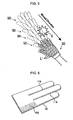
- Figure 4 shows the back side of hand of the convex or concave surface curvature position exhibiting device, while right part shows the palm side of hand of it.
- Figure 5 shows the convex or concave surface curvature position exhibiting method using the convex or concave surface curvature detected position exhibiting device.
- the sensing-and-exhibiting member 50 preferably has the bag-shape including two sheets 51 and 52 each having the shape of human hand shape.
- the operator can wear the sensing-and-exhibiting member 50 on the hand.
- the sheet 51 (sensing portion) positioned at the palm side of hand is provided with plural sensors S' as the deformation sensing device on an outer surface thereof by the constant interval.
- the plural sensors which sense same direction are arranged on the line.
- the sensors S' are comprised of the above deformation sensing device, they are preferably arranged in the direction extending from a wrist to fingertip.
- the light emitters L' preferably comprised the exhibiting portion, are arranged by the same mode of the sensors S'.
- the light emitters L' corresponding to the sensors S' having detected the convex or concave surface curvature are to be lighted. Some of the sensors and some of the light emitters are added reference S 1 ' to S 15 ', and L 1 ', to L 15 ' in Figure 10. Sn' on the palm side of hand (sheet 51) and Ln' on the back side of hand (sheet 52) are corresponded to each other. For example, when the sensor S 1 ' detects the convex or concave surface curvature, the light emitter L 1 ' emits the light.
- the sensor S 1 ', S 2 ' - and the light emitters L 1 ', L 2 ' - operate similarly.
- the operator wears the sensing-and-exhibiting member 50 on the right hand, for example.
- the sensing-and-exhibiting member 50 is moved, with the sheet 51 being contacted with the object surface, in the direction from the fingertip to the wrist as shown by the arrow in Figure 11.
- Plural light emitters L' are put on/off continuously.
- the light emitters L' passing over the convex or concave surface curvature emit the light (refer to the mark E), which enables the operator to visually recognize the position of convex or concave surface curvature.
- FIG. 6 show the whole convex or concave surface curvature amplifying device of the embodiment
- Figure 7 is a partially enlarged plan view of the same
- Figure 8 is a cross-section along line X-X' in Figure 7
- Figure 9 is an explanatory view for explaining convex or concave surface curvature detection by the convex or concave surface curvature amplifying device.
- the convex or concave surface curvature amplifying device is comprised of a sheet-like base portion 101 operating as the sensing member, and plural protrusions 102 formed integral with the base portion 101 to operate as the exhibiting member 120.
- the base portion 101 has the thickness of 0.3 mm, the width of 60.0 mm, and length (max.) of 133.5 mm. Two slits 115 extending longitudinally from one end are formed in parallel (refer to Figure 12). Thus, the base portion 101 is divided into the first portion, second portion and third portion on which the forefinger, the middle finger and the ringfinger are rested respectively. For operation, the convexo concave amplifying device is pushed by the fronts of three fingers and the central portion of the palm of hand.
- the plural protrusions 102 are formed on an upper surface as a whole (refer to Figure 14). They are positioned at the cross points of the triangular grids of which side has length of about 1.7 mm.
- Each protrusion 102 has a small column shape of which diameter is 1 mm and height is 3.2 mm, and upstanding in the thickness direction of the base portion 101.
- the top portion of the protrusion has a semispherical shape of which diameter is 1 mm.
- the convex or concave surface curvature amplifying device having the base portion 101 and the plural protrusions 102 is made of the photo-curing resin of which elastic modulus is 2400 MPa and formed by the stereolithography device.
- a tape (not shown) for reducing the friction is attached.
- the convex or concave surface curvature amplifying device For detecting the convex or concave surface curvature by the finger and the palm, the convex or concave surface curvature amplifying device is pressed onto the object surface by the pressure of 0.01 to 0.02 MPa, and is reciprocately slid by the speed of 100 mm/sec.
- the convex or concave surface curvature amplifying device of the embodiment can easily and clearly detect the convex curvature which can be hardly detected by the polyethylene film.
- the simulation using the finite element method (FEM) the time dependent variation of strain transmitted to the Meissner's corpuscle in the shearing direction is amplified by 20 times by the convex or concave surface curvature amplifying device, compared with the case by the bare hand.
Landscapes
- Health & Medical Sciences (AREA)
- Life Sciences & Earth Sciences (AREA)
- Physics & Mathematics (AREA)
- Medical Informatics (AREA)
- Surgery (AREA)
- Pathology (AREA)
- Veterinary Medicine (AREA)
- Engineering & Computer Science (AREA)
- Biomedical Technology (AREA)
- Heart & Thoracic Surgery (AREA)
- Biophysics (AREA)
- Molecular Biology (AREA)
- Public Health (AREA)
- Animal Behavior & Ethology (AREA)
- General Health & Medical Sciences (AREA)
- Dermatology (AREA)
- Nuclear Medicine, Radiotherapy & Molecular Imaging (AREA)
- Radiology & Medical Imaging (AREA)
- General Physics & Mathematics (AREA)
- Measurement Of Length, Angles, Or The Like Using Electric Or Magnetic Means (AREA)
Abstract
Description
- The present invention relates to a convex or concave surface curvature amplifying device and a convex or concave surface curvature detecting method using it, to be used for detecting a convex or concave surface curvature of an object such as a surface of a steel plate.
- In the following, a background art of a convex or concave surface curvature amplifying device and a convex or concave surface curvature detecting method using it will be explained. In a field of a tactile substitution and an artificial reality, many studies have been made for exhibiting an artificial feeling for human. For example, a tactile sensing exhibiting system whose sensing portion and displaying portion are disposed on the two sides thereof has been developed. An optical sensor reading a printed matter and a touch sensor are disposed as the sensing portion. For the displaying portion, a method of exhibiting the artificial tactile sensing by electrically stimulating a tactile receptor is adapted. Thus, this tactile sensing exhibiting system can exhibit the feeling of touching the thing which the user can not feel by himself.
- However, the resolution and the sensitivity of the sensing portion and the displaying portion are insufficient. Also, the tactile sensing exhibiting system using a complex mechatronics technique is apt to invite trouble due to the complex structure. Thus, much time and labor are required for the maintenance. Further, sensing portion and the display portion can hardly be downsized.
US 4, 657, 021 andUS 4, 793, 354 disclose means for easily detecting or sensing the convex or concave surface curvature of the object. The detecting means is a touch enhancing pad comprised of two flexible sheets, and a small amount of lubricant oil sealed between the two sheets. In using the touch enhancing pad, with one sheet being contacted and rested on a surface of a subject, the other sheet in contact with the finger is moved together with the finger. As a result, movement of the lubricant oil reduces influence of friction between the subj ect and the fingertip, whereby the convex or concave surface curvature of the object can be clearly detected by smooth moving of the finger-tip. This touch enhancing pad has been put into the market by the name of "BSE (Breast Self-Examination) Pad", and is approved by FDA as a self-examination assisting tool for the breast cancer. Generally, the tactile sensing of the finger may get dull on the condition that some intervening material is interposed between the surface of the object and the finger tip. This pad can, without using the complex mechatronics technique, detect the convex or concave surface curvature of the object clearly. However, it can hardly detect the small or fine convex or concave surface curvature, and is not practical as the tool to detect the convex or concave surface curvature of the object extensively. Further, though it has a simple construction that the lubricant oil is sealed between the two sheets, it has to be feared that the lubricant oil is leaked by the damage of the sheet. - The technique for detecting the convex or concave surface curvature of the object has been required in many fields. In the convex or concave surface curvature detecting method, the subject (surface of the object) has been inspected by contacting for example a dialogue type sensor (contact type), or by an image processing (non-contact type). However, the former type is not suitable for the extensive inspection of the object. The latter type suffers from dispersion of the detected result due to luster and blot existing on the surface of the object. Further, the both types require expensive apparatus and much time for setting. Therefore, in the strain inspection of a steel plate of manufacturing process in practice, for example, vehicle manufacturing process, skilled workers detect the convex or concave surface curvature by hand. However, difference in degree of skill brings different result of the detection. In addition, long period is required for the workers to acquire the skill of detecting the convex or concave surface curvature. For this reason, the detecting method which can be carried out cheaply and which can detect the convex or concave surface curvature easily has been required.
- From
WO 00/66970 A US 6,445,284 B1 , there is known a tactile transducer to provide a tactile display or serve as a tactile input sensor. Paired contactors having contactor tips separated by a gap are connected to an actuator or sensor. Variations in the gap distance can create a tactile experience through skin stretch, or provide tactile input in sensor made. FromUS 6, 179, 790 B1 , there is known a method for detecting breast cancer wherein a sensor array is pressed against tissue. It is described to translate the sensor array over the tissue to allow the user to increase breast area coverage with less exam time. By taking the above circumstances into consideration, the object of the invention is to provide a convex or concave surface curvature amplifying device which has a simple construction and can exhibit a convex or concave surface curvature by amplifying a sense of a convex or concave surface curvature of the object and to a convex or concave surface curvature detecting method which detects the convex or concave surface curvature of the object by using the convex or concave surface curvature amplifying device. - The object of the invention is attained by a convex or concave surface curvature amplifying device according to
claim 1 or a convex or concave surface curvature detecting method according to claim 9. Further developments of the invention are characterized in the dependent claims. - A convex or concave surface curvature amplifying device for exhibiting a convex or concave surface curvature by amplifying a sense of a convex or concave surface curvature of an object of the present invention comprises a sensing member comprising a flexible sheet able to contact with the surface of the object and to deform along the surface of the object; and an exhibiting member (for transducing a surface curvature) that is formed on a surface of the flexible sheet and has a deformation resistance smaller than that of the flexible sheet in at least one of directions orthogonal to a direction of thickness of the flexible sheet. According to this construction, the convex or concave surface curvature amplifying device is able to exhibit or transduce the convex or concave surface curvature by that the exhibiting member exactly amplifies the sense of the convex or concave surface curvature of the obj ect, which is sensed by the sheet member. Without the use of a complex mechatronics technique, the convex or concave surface curvature amplifying device has a simple configuration comprising the sensing member and exhibiting member so that breakdown or breakage hardly happens and the cost is low.
-
-
Figure 1(a) schematically shows elasticity (expansion and contraction) occurred when the conventional sheet contact with the convex surface of an object, 1(b) shows elasticity occurred when the conventional sheet contact with the concave surface curvature of the object; -
Figure 2 schematically shows deformation of the sensing member and the exhibiting member when the convex or concave surface curvature amplifying device of the present invention is in contact with the flat surface (shown by the dotted line) and the inclined surface (shown by the solid line); -
Figure 3 (I) is an enlarged cross-sectional view along a line V-V' inFigure 3(II), and Figure 3(II) is an enlarged cross-sectional view along a line W-W' inFigure 3(I) ; -
Figure 4 are the plane views showing one example of a convex or concave surface curvature position exhibiting device when it is viewed from the back side of hand (left figure) and from the palm side of hand (right figure); -
Figure 5 is an explanatory view showing the convex or concave surface curvature position exhibiting method by the convex or concave surface curvature position exhibiting device; -
Figure 6 is a concept view showing the whole convex or concave surface curvature amplifying device according to an embodiment; -
Figure 7 is an enlarged plan view of the convex or concave surface curvature amplifying device ofFigure 6 ; -
Figure 8 is a cross-sectional view along a line X-X' inFigure 7 ; -
Figure 9 partially shows detecting manner for detecting the convex or concave surface curvature of the object by the convex or concave surface curvature amplifying device of the embodiment; - In the following, best modes of a convex or concave surface curvature amplifying device and a convex or concave surface curvature detecting method of the present invention, will be explained with
Figures 1 to 3 . Further, a convex or concave surface curvature position exhibiting device and a convex or concave surface curvature position exhibiting method will be explained withFigures 4 and5 . - A convex or concave surface curvature amplifying device of the present invention senses a convex or concave surface curvature of an object to exhibit or transduce it with amplification. When a sheet having a constant composition and a constant thickness is contacted with a surface of an object at one surface (a lower surface, for example), the sheet deforms or deflects along the convex or concave surface curvature of the object. In the deflection, expansion and contraction occur in an upper and a lower surfaces of the sheet. Concretely, as shown in
Figure 1 schematically, when thesheet 110 is mechanically adapted to (contactedwith) the convex surface of the object, expansion occurs in theupper surface 110u while contraction occurs in thelower surface 110d (refer toFigure 1(a) ). When thesheet 110 is mechanically contacted with the concave surface, reversed phenomenon occurs (refer toFigure (1b )). - In both cases, an intermediate or neutral surface M not expanding and contracting exists in the
sheet 110. As the upper surface of the sheet goes away from the intermediate surface M, that is as thickness of the sheet becomes larger, expansion/contraction amount of the sheet upper surface becomes larger. Thus, for exhibiting the convex or concave surface curvature detected on the upper surface with amplification, thickness of the sheet is desirably increased to make deformed amount of the sheet upper surface larger. - However, in the general sheet which is isotropic and has constant thickness, flexibility is lowered when the sheet thickness is increased (bending rigidity is proportional to cube of thickness) . For this reason, the thicker sheet which is hardly mechanically contacted with the obj ect surface (surface of the obj ect) at the lower surface thereof, can not sense the the convex or concave surface curvature of the object accurately. If the sheet of lower elastic modulus is used, it is compressed in the thickness direction by pressing force applied. Thus, the convex or concave surface curvature detected by the lower surface is hardly transmitted to the upper surface.
- In view of the above, the convex or concave surface curvature amplifying device of the present invention is comprised of a sensing member, and an exhibiting member. The sensing member is comprising a flexible sheet to be able to contact with the surface of the object and to deform along the surface of the object. The exhibiting member is formed on a surface of the flexible sheet. Deformation resistance of the exhibiting member is smaller than that of the flexible sheet in at least one of directions orthogonal to a direction of thickness (extended or spread direction) of the flexible sheet.
- When the sensing member constructing the convex or concave surface curvature amplifying device is mechanically contacted with the object at one surface (hereinafter, briefly called "lower surface of the sensing member"), it deforms following to the object surface due to flexibility thereof. The exhibiting member on the other surface of the sensing member (hereinafter briefly called "upper surface of the sensing member") also deforms.
- Deformation resistance of the exhibiting member in at least one direction in the spread direction is smaller than that of the sensing member in the same direction. Thus, the flexibility of the sensing member is not degraded even if the thickness of the convex or concave surface curvature amplifying device is large as a whole. As a result, the exhibiting member can effectively exhibit the convex or concave surface curvature of the object sensed with amplification. In the following, the principle will be explained concretely.
- In
Figure 2 , a convex or concave surface curvature amplifying device is shown schematically in the two-dimensional space. It is comprised of asensing member 111, and an exhibitingmember 121 formed on thesensing member 111. A deformation resistance of the exhibitingmember 121 in the spread direction of thesensing member 111 is small. The exhibitingmember 121 includes plural pin-like protrusions 126 extending in the thickness direction (up-down direction inFigure 2 ), and separated equidistantly in the spread direction (lateral direction inFigure 2 ). Namely, the deformation resistance of the exhibitingmember 121 in the lateral direction is smaller than that of thesensing member 111 in the same direction. - In
Figure 2 , the convex or concave surface curvature amplifying device put on a flat (standard) surface is shown by a dotted line, while that put on an inclined surface (inclined angle:θ) is shown by a solid line. When the convex or concave surface curvature amplifying device is put on the inclined surface, theprotrusions 126 of the exhibitingmember 121 deform or incline in a normal direction and a tangential direction of the standard surface. Provided that the neutral surface M exists in thesensing member 111 and thickness of thesensing member 111 is extremely small, deformation or inclination of theprotrusions 126 in the tangential direction is proportional to product of the inclined angle θ of the inclined surface Ob, and thickness T of the convex or concave surface curvature amplifying device. Here, thickness T is sum of thickness of thesensing member 111 and length of theprotrusions 126. Inclination of theprotrusions 126 in the normal direction is equal to height H of the inclined surface Ob. - Summing up, thanks to the convex or concave surface curvature amplifying device of the present invention comprised of the sensing member and the exhibiting member, the thicker or longer exhibiting member can amplify and exhibit convex or concave surface curvature of the object sensed by the sensing member accurately.
- In the convex or concave surface curvature amplifying device, deformation resistance of the exhibiting member in at least one direction in the spread direction is smaller than that of the sensing member in the same direction. The intermediate surface M at which no expansion or contraction occurs, positions remote from the surface of exhibiting member. For this reason, convex or concave surface curvature of the object sensed by the sensing member can be effectively amplified by the exhibiting member to be exhibited on the surface thereof.
- Further, thanks to the above structure, even if thickness or length from the intermediate surface M to the exhibiting member surface is selected larger, flexibility of sensing member does not decrease, and the amplifying effect of the exhibiting member increases.
- By selecting thickness of the sensing member smaller and the thickness of the exhibiting member larger, the convex or concave surface curvature amplifying device convenient to effectively senses convex or concave surface curvature of the object , amplifies and exhibits the sensed convex or concave surface curvature can be obtained. For example, ratio between thickness of the sensing member and length of the exhibiting member can range from 1:10 to 1:100.
- In the convex or concave surface curvature amplifying device of the present invention, the sensing member has flexibility to deform following (tracing) along the object surface. This is because the lower surface of the sensing member is contacted (touched) with the object surface, or it is pressed onto the object surface. Preferable the elastic modulus of the sensing member ranges from 500 to 3000 MPa, 1500 to 2500 MPa is more preferable. For realizing such elastic modulus, the sensing member can be made of resin such as polyethyleneterephthalate (PET), polyacetal or polycarbonate. Preferable thickness of the sensingmember ranges from 0.05 to 0.5 mm, depending on the elastic modulus.
- The convex or concave surface curvature amplifying device in which the elastic modulus and thickness of the sensing member are selected in the above ranges, can easily deform following the object surface at one surface thereof. Thus, the convex or concave surface curvature amplifying device is effectively used to sense the convex or concave surface curvature of the object. Thanks to small expansion and contraction of the sensing member in the thickness direction, the sensing member can hold the spatial information of the convex or concave surface curvature of the object to transmit as the information in the thickness direction. When selecting material of the sensing member, the friction between the lower surface of it and the obj ect surface is preferably considered. Small friction is preferable to obtain smooth and easy sliding of the convex or concave surface curvature amplifying device on the object surface (to be explained later). If the material of the sensing member increases the friction, another member which can reduce the friction but does not decrease flexibility of the sensing member, can be added on the lower surface of the sensing member. For such added member, a film or a tape made of material different from the material of sensing member can be adopted.
- The exhibiting member of the convex or concave surface curvature amplifying device of the present invention is formed on the other surface (for example upper surface) opposite to that surface (for example lower surface) of the sensing member that is in contact with the object. It can be formed integrally with the sensing member.
- The exhibiting member has a deformation resistance smaller than that of the flexible sheet in at least one of directions orthogonal to a direction of thickness of the flexible sheet. Material and shape of the exhibiting member not reducing flexibility of the sensing member are preferably selected. The exhibiting member has a rigidity not generating expansion and contraction, when the surface of the exhibiting member is compressed in the thickness direction of the convex or concave surface curvature amplifying device.
- As the material of the exhibiting member, an anisotropy material of which the deformation resistance differs depending on the deforming direction is preferably adopted. A reinforced fiber plastic and a high function resin can be exemplified. In addition to the single layer construction of the exhibiting member (the convex or concave surface curvature amplifying device has the double construction of the sensing member and the exhibiting member), the exhibiting member can have plural-layer construction. In such exhibiting member, plural layers having the deformation resistance of which direction and value are different from that of the sensing member can be adopted. Also, the direction and value of the deforming resistance can be gradually varied from the one surface to the other surface. In such case, selecting the deformation resistance at the front surface of the exhibiting member smaller is preferable.
- The exhibiting member can be made of foam, and a sheet provided with plural holes. In the convex or concave surface curvature amplifying device schematically shown in
Figure 3 , the exhibiting member is constructed by the sheet having plural holes extending in a direction of the thickness thereof. The convex or concave surface curvature amplifying device is comprised of asensing member 113, and a exhibitingmember 130 constructed by the sheet. They are integrally constructed by resin material. The exhibitingmember 130 is provided with plural vertical dead endedholes 103 extending vertically from the upper surface thereof. Thevertical holes 103 make the deformation resistance of the exhibitingmember 130 in the spread direction of sensing member smaller than that of thesensing member 113 in the same direction. The sensingmember 113 and the exhibitingmember 130 separately formed can be fixed integral each other. The holes can be formed in a direction to make a predetermined angle relative to the thickness direction of the sensing member. - The exhibiting member is preferably comprised of plural protrusions spaced to each other and formed on the surface of the flexible sheet. The exhibiting member preferably has rigidity not to be expanded or contracted in the length direction thereof even when tip ends of the protrusions (surface of the exhibiting member) are pressed, and to maintain the angle of the protrusions relative to the sensing member constant. With inclination of the protrusions by the predetermined angle, the tip ends of the protrusions displace or shift by the predetermined amount, to thereby amplify and to exhibit the convex or concave surface curvature of the object detected by the sensing member. The preferable elastic modulus of the protrusions ranges from 1500 to 5000 MPa, and 2000 to 4000 MPa is more preferable. For realizing such value of elastic modulus, the protrusions can be made of resin such as PET, polyacetal, ploycarbonate and acryl etc., and metal such as aluminum etc. The protrusions having such range of the elastic modulus do not degrade the flexibility of the sensing member.
- There is no restriction for shape of the protrusions. A cone shape and pyramid shape, a column shape and cylinder shape, and plate shape and napping shape can exhibit the convex or concave surface curvature amplifying effect. The tip end of the protrusion can have a sharp shape, flat shape and curved shape. When the protrusion has the cone shape or the column shape, a hemisphere tip end is preferable.
- There is no restriction for arrangement of the protrusions. They can be arranged at random, but arranging the protrusion by the predetermined interval in the two-dimensional space is preferable. In view of shape and size of the protrusions, the interval of 0.5 to 2.0 mm is preferable. The protrusions can position at cross points of grids, and can be arranged in parallel to each other, or to cross with each other. For example, in the protrusions constructed by the plural plates arranged in parallel each other, the deformation resistance in the spread direction of the sensing member, and orthogonal to the arranged direction of the protrusions can be made smaller.
- The protrusions constructed by the plural columns arranged by the predetermined interval can decrease the deformation resistance in the spread direction of the sensing member.
- The plural protrusions are preferably arranged so that the tip ends thereof are directed in parallel. In such arrangement, all of the protrusions displace by the same amount relative to the convex or concave surface curvature of the object, to amplify the convex or concave surface curvature. For example, when the plural protrusions are constructed by the columns extending in the thickness direction of the sensing member, the expansion or contraction hardly occurs even if the tip ends thereof are compressed, whereby the convex or concave surface curvature amplifying device is contacted with the object. Also, such protrusions easily hold vertical posture so that the exhibiting member surface (tip end of the plural protrusions) can accurately amplify and exhibit the convex or concave surface curvature of the object.
- As thickness of the convex or concave surface curvature amplifying device becomes larger, that is as the protrusions become longer, the amplifying effect increases. For this reason, length of the protrusion can preferably selected longer, so long as no expansion or contraction occurs during usage. In view of the shape and material, the preferable length of the protrusion is not less than 2.5 mm. The length of 3 to 6 mm is more preferable. The column-shaped and cone-shaped protrusions preferably has diameter of 1 to 1.5 mm at a connecting part between the protrusion and the sensing member. The protrusions having such diameter do not reduce flexibility of the sensing member.
- Selecting the material and thickness of the sensing member and the exhibiting member, and selecting the shape of the exhibiting member, can vary the amount of the deformation resistance and deformed degree of the exhibiting member. Thus, value of the flexibility of the sensing member and the amplifying operation of the convex or concave surface curvature amplifying device can be varied. The material, thickness and shape can be selected in view of the quality (resolution of convex or concave surface curvature) and usage. Also filling in the hollow space of the hole (for example,
vertical hole 103 ofFig. 3 ) and space formed between the adjacent protrusions of the exhibiting member with variousfilling material can adjust the deformation resistance of the exhibiting member. The sensing member and the exhibiting member independently prepared can be joined, or the sensing member and the exhibiting member can be made integral by one body of the same material. In the latter case, preferable elastic modulus is 1500 to 3000 MPa, and 2400 to 2500 MPa is more preferable. For the manufacturing of the sensing member and exhibiting member, various forming method using the molds and stereolithography can be adopted. - The exhibiting member preferably has a strain sensing tool for detecting strain thereof. For example, a strain gauge can be exemplified. The strain gauge of an electrical resistance type can convert the physical deformation of the exhibiting member to the electrical signal. The strain sensing tool sensing deformation of the exhibiting member surface can sense the convex or concave surface curvature of the object in the higher accuracy, because the convex or concave surface curvature of the object is amplified by the exhibiting member surface. The strain sensing tool can be disposed at any position where it can sense deformation of the exhibiting member.
- This convex or concave surface curvature detecting method is comprised of a contacting step, and a detecting step. In the contacting step, the sensing member is contacted with a surface of the object and the flexible sheet of the sensing member is deformed along the surface of the object. In the detecting step, the convex or concave surface curvature is detected by sensing a deformation of the exhibiting member induced in the contacting step.
- As partially explained in the above, the exhibiting member formed on the sensing member deforms following to the convex or concave surface curvature of the object sensed by the sensing member. The exhibiting member deforms corresponding to surface shape of the object (flat or inclined, refer to
Figure 2 ). Sensing deformation of the exhibiting member on the condition that the sensing member is contacted with the convex or concave surface curvature of the object can detect the convex or concave surface curvature of the object. - The convex or concave surface curvature detecting method can also detect convex or concave surface curvature within the object comprised of a convex or concave surface curvature portion, and a surface portion covering it. In the contacting step, the sensing member of the convex or concave surface curvature amplifying device is pressed onto the obj ect and is deformed along the surface of the object. The convex or concave surface curvature amplifying device can, in the detecting step, detect the convex or concave surface curvature of the convex or concave surface curvature portion. Thus, the convex or concave surface curvature detecting method can detect a small foreign matter enteredbelow the flexible thing such as the sheet, and lump in the skin.
- There is no restriction for the sensing deformation of the exhibiting member. However, in the contacting step, the convex or concave surface curvature amplifying device contacted with the surface of the object is slid, thereby an amount of the deformation of the exhibiting member is induced to depend on time. In the detecting step, a variation of a time-dependent amount of the deformation of the exhibiting member is sensed by a tactile sense. Hereinafter, sensing method by the tactile will be explained.
- A human skin having the tactile is comprised of three layers of different softness. They are arranged in the order of a epidermis (surface skin), dermis and hypodermic tissue from outside . Inside of the human skin where no hair is grown, there are four feeling receptive organs (Meissner's corpuscle, Merkel disk receptor , Pacinian corpuscle and Ruffini ending). They convert the strain information of the skin tissue to the electrical pulse, then the electrical pulse is transmitted to a central nervous system to generate the skin feeling.
- These feeling receptive organs are positioned at different depth from the surface skin, and are characterized by size of receptive field (area on the skin surface where receptive organs receive the stimulus) and speed to adaptation. Among the four feeling receptive organs, Meissner's corpuscle positioned at boundary between the epidermis and the dermis, has high spatial resolution due to narrow receptive field, and has quick adaptation. It contributes, when a palm of hand or a finger is contacted with the object surface to follow it, to separate the feeling stimulus resulting from the convex or concave surface curvature of the object. Thus, the position and shape of the convex or concave surface curvature are sensed. When the convex or concave surface curvature amplifying device is used to detect the convex or concave surface curvature of the object, amplifying the stimulus reached to Meissner's corpuscle is effective.
- The Meissner's corpuscle, in recognizing the convex or concave surface curvature of the object, generates the electrical pulse corresponding to strain variation relative to lapse of time, not corresponding to the absolute amount of strain. Through structural analysis of Meissner's corpuscle, the time dependent strain variation in the shearing direction is suitable stimulus for the Meissner's corpuscle, has been well-known.
- In the contacting step, the convex or concave surface curvature amplifying device is compressed onto the object surface by the skin such as the palm of hand having the tactile sensing to be mechanically contacted thereto. The convex or concave surface curvature amplifying device is slid together with the hand on the object surface so that displacement in the tangential and normal directions of the exhibiting member surface varies as the time passes. In the detecting step, time dependent displacement variation in the tangential direction acted onto the skin is transmitted to Meissner corpuscle in the skin, as the strain variation in the shearing direction which is suitable stimulus for the Meissner's corpuscle.
- As partially explained, because the tangential displacement or inclination on the exhibiting member surface is proportional to inclination of the object surface and thickness of the convex or concave surface curvature amplifying device, it is transmitted to the Meissner's corpuscle after being amplified by length of the exhibiting member. For this reason, when the convex or concave surface curvature of the object is detected by the tactile sense, sliding the convex or concave surface curvature amplifying device contacted with the object convexo concave by the hand is preferable.
- When the exhibiting member of the convex or concave surface curvature amplifying device is constructed by the protrusions, the time dependent strain variation in the shearing direction easily generates in the skin. Such strain variation is resulted from displacement variation of the tip ends of protrusions in the tangential direction. This is because the tangential displacement dispersedly applied at the tip ends of the protrusions to the skin easily generates the shearing strain. The tangential displacement is determined corresponding to height of the convex or concave surface curvature of the object. The information of time dependent displacement variation is converted to the strain variation of the Meissner's corpuscle in the shearing direction.
- For the above reason, according to the convex or concave surface curvature detecting method, shape (inclination and height) of the object can be amplified and converted to strain variation in the shearing direction effectively at the position of Meissner ' s corpuscle by displacement variation of the exhibiting member surface of the convex or concave surface curvature amplifying device.
- Further, according to the convex or concave surface curvature detecting method, the palm of hand etc. is slid, on the object surface via the convex or concave surface curvature amplifying device having the sensing member of which lower surface is of the low friction. As a result, the friction between the sensing member and the object surface reduces to prevent a stick-slip vibration which may get dull the feeling. Reducing the friction which may become noise and the contacting stimulus resulting from vibration can make the sensation of the convex or concave surface curvature clearer. The tip ends of the exhibiting member constructed by the plural protrusions contribute to prevent slippage between the convex or concave surface curvature amplifying device and the skin.
- The convex or concave surface curvature detecting method using the detecting method by the tactile sensing, can be applied to a surface inspection of deformation existing on a surface of steel plate, in the vehicle manufacturing and ship-building. The surface inspection has been carried out conventionally by the skilled worker by moving the palm of hand along the steel plate surface. The convex or concave surface curvature amplifying device used in the convex or concave surface curvature detecting method is portable due to the simple construction thereof. In the working spot where work gloves are indispensable, the convex or concave surface curvature amplifying device can be used by building it in the work glove. Thus, usage of the convex or concave surface curvature amplifying device is enlarged.
- The convex or concave surface curvature amplifying device and the convex or concave surface curvature detecting method can be utilized in a training of beginners who are working at the surface inspection. In the conventional training, the beginners should continue to trace the object surface until they detect the surface strain even when it seems flat for them. The convex or concave surface curvature amplifying device and the convex or concave surface curvature detecting method of the present invention capable of sensing the extremely small surface convex or concave surface curvature can acquire experience (scent) about position, size and shape of the surface convex or concave surface curvature easily.
- The surface inspection using the acquired experiences enables sensing of the small convex or concave surface curvature of the object without the convex or concave surface curvature amplifying device. Thus, training effect of the tactile ability for the training workers is improved, so that the surface detecting skill can be succeeded via the convex or concave surface curvature amplifying device of the present invention.
- As partially explained, the convex or concave surface curvature amplifying device can adjust the convex or concave surface curvature amplifying degree thereof by changing of the material and thickness thereof, and construction of the exhibiting member. The beginner can increase the training efficiency by properly selecting various kinds of the convex or concave surface curvature amplifying device according to the trained level. In the surface inspection of the vehicle manufacturing, the different kinds of convex or concave surface curvature amplifying devices having different amplifying degree can be used for every kinds of the vehicle. Thus, the inspection level can be easily set corresponding to the kinds of vehicles.
- The convex or concave surface curvature position exhibiting device is comprisedof a sensing-and-exhibitingmember, andacontrolling member.
- The sensing-and-exhibiting member comprises a sensing portion and an exhibiting portion. The sensing portion comprises plural deformation sensing device of sensing a deformation thereof caused by a convex or concave surface curvature of the object. The exhibiting portion comprises plural light emitters and located opposite to the sensing portion. The controlling member controls the light emitters to emit light depending on a result of sensing by the deformation sensing device.
- In the sensing-and-exhibiting member, the sensing portion and the exhibiting portion are disposed by the front and rear relation. Accordingly, operator can visually recognize the detected position on the object surface by the emitted light of the exhibiting portion. Any position sensor for measuring the position where the convex or concave surface curvature is detected need not be provided. When the convex or concave surface curvature position exhibiting device is slid on the object surface in high speed so that the sensing portion sense the convex or concave surface curvature, the exhibiting portions continuously emit the light corresponding to the detected convex or concave surface curvature. The light of the light emitters remain in the operator's retina as the residual image of light, whereby the operator can visually recognize the convex or concave surface curvature position on the object surface.
- There is no restriction for the deformation sensing device of the sensing portion, so long as it can sense the convex or concave surface curvature of the object by the relative movement between the sensing portion and the object surface. In addition to the conventional sensor such as the strain gauge and the PVDF sensor, the above mentionedconvex or concave surface curvature amplifying device can be exemplified, as the deformation sensing device. The plural deformation sensing devices can be arranged in the sheet-shape to form the sensing portion.
- There is no restriction for the exhibiting portion, so long as it can emit the light. The light emitters which can emit the light of high visible characteristic sufficiently strongly, such as the light emitting diode, is preferably used.
- The controlling member for causing the light emitter to emit the light preferably has the thresholds set in advance. Based on comparison of the threshold with the degree of detected convex or concave surface curvature, it judges presence/absence of the convex or concave surface curvature to control put-on/put-off of the light emitter. By changing the value of threshold, sensitivity of convex or concave surface curvature position exhibiting device can be adjusted arbitrarily. The color and intensity of the emitted light of the light emitter can be changed corresponding to the detected degree.
- There is no restriction of the material and shape for the sensing portion and the exhibiting portion. They preferably have sheet shape. The sensing portion contacting with the object surface preferably has the softness to follow to the object surface. Concretely, the resin sheet such as the nylon and vinyl, and the fiber sheet such as the fabric and felt can be exemplified. The sensing-and-exhibiting member preferably has the shape so that the operator can use it by the hand. It can have the bag-shape in which the sensing portion positions at the palm side of hand, while the exhibiting portion positions at the back side of hand. For example, arranging the deformation sensing device and the light emitters respectively at the palm side and the back side of the bag-shaped body such as the work glove and the vinyl glove hand can realize the portable sensing-and-exhibiting member. There is no restriction of arrangement of the deformation sensing device so long as it is fixed to one surface of the sensing portion. Plural deformation sensing devices can be arranged at random on the sensing portion by the predetermined pattern to cover the whole surface of it, or by the predetermined intervals. The plural deformation sensing devices are preferably arranged in the same pattern as the plural light emitters mentioned above. The controlling member preferably has a controlling portion to cause some of the light emitters, arranged in the same pattern as the plural deformation sensing devices, to emit the light. Thus, the light emitter corresponding to the deformation sensing device having detected the convex or concave surface curvature, emits the light to exhibit the convex or concave surface curvature position accurately.
- The convex or concave surface curvature position exhibiting method of the present invention is comprised of a relative moving step, a detecting step and an exhibiting step.
- In the relative moving step, the deformation sensing device and the object are moved relatively on the condition that the deformation sensing device is contacted with a surface of the object. The detecting step detects the convex or concave surface curvature by that the deformation sensing device senses a deformation thereof caused by a convex or concave surface curvature of the object. The relative movement makes the position detection of convex or concave surface curvature in larger area possible.
- There is no restriction of deformation sensing device so long as it can detect the convex or concave surface curvature on the object. In addition to the conventional sensors such as the strain sensor and the PVDF sensor, the convex or concave surface curvature amplifying device mentioned above can be exemplified. For carrying out the convex or concave surface curvature detecting step, the deformation sensing device and the convex or concave surface curvature position exhibiting device above mentioned can be used. The deformation sensing device contacted with the object surface is preferably slid or moved. The deformation sensing device can be slid relative to the object mechanically, but sliding it manually is preferable.
- In the exhibiting step, the position of convex or concave surface curvature on the object surface is time-dependently exhibited by emitting light depending on the detected result in the relative moving step and the detecting step. Thanks to the time-dependent light emission, position of the convex or concave surface curvature can be accurately judged.
- The convex or concave surface curvature position exhibiting method can additionally include a judging step. It judges presence/absence of the exhibiting in the exhibiting step, based on the degree of convex or concave surface curvature detected in the relative moving step and the detecting step. When the convex or concave surface curvature position exhibiting method is applied to the surface inspection of the steel plate, the judging step contributes to find out the bad or rough surface by the predetermined surface accuracy.
- In the exhibiting step, a position of a convex or concave surface curvature on a surface of the object is preferably exhibited on the surface of the object by emitting light at the position where the convex or concave surface curvature exists. The exhibiting step preferably exhibits (emits light) at the position just above the convex or concave surface curvature of the object. Arranging the light emitter at the same position as the deformation sensing device enables the operator to visually recognize the accurate position of the convex or concave surface curvature.
- For carrying out the convex or concave surface curvature position exhibiting method, the deformation sensing device having the light emitter as a exhibiting tool, and the convex or concave surface curvature position exhibiting device above mentioned can be used. In sliding the convex or concave surface curvature position exhibiting device on the obj ect surface, the plural light emitters emit the light continuously, whereby the operator can visually recognize position of the convex or concave surface curvature. One example of the convex or concave surface curvature position exhibiting method of the present invention will be explained with reference to
Figures 4 and5 . Left part ofFigure 4 shows the back side of hand of the convex or concave surface curvature position exhibiting device, while right part shows the palm side of hand of it.Figure 5 shows the convex or concave surface curvature position exhibiting method using the convex or concave surface curvature detected position exhibiting device. - The sensing-and-exhibiting
member 50 preferably has the bag-shape including twosheets member 50 on the hand. The sheet 51 (sensing portion) positioned at the palm side of hand is provided with plural sensors S' as the deformation sensing device on an outer surface thereof by the constant interval. When the detecting area is extended in one direction, the plural sensors which sense same direction are arranged on the line. When the sensors S' are comprised of the above deformation sensing device, they are preferably arranged in the direction extending from a wrist to fingertip. By moving the sensing-and-exhibitingmember 50 in the direction where the sensors are arranged, the convex or concave surface curvature can be detected (to be explained later). - On the sheet 52 (exhibiting portion) positioned at the back side of hand is preferably provided with plural light emitters L' on an outer surface thereof. The light emitters L' preferably comprised the exhibiting portion, are arranged by the same mode of the sensors S'.
- The light emitters L' corresponding to the sensors S' having detected the convex or concave surface curvature are to be lighted. Some of the sensors and some of the light emitters are added reference S1' to S15', and L1', to L15' in Figure 10. Sn' on the palm side of hand (sheet 51) and Ln' on the back side of hand (sheet 52) are corresponded to each other. For example, when the sensor S1' detects the convex or concave surface curvature, the light emitter L1' emits the light. The sensor S1', S2' - and the light emitters L1', L2' - operate similarly.
- In detecting the object convex or concave surface curvature, the operator wears the sensing-and-exhibiting
member 50 on the right hand, for example. The sensing-and-exhibitingmember 50 is moved, with thesheet 51 being contacted with the object surface, in the direction from the fingertip to the wrist as shown by the arrow in Figure 11. Plural light emitters L' are put on/off continuously. Here, the light emitters L' passing over the convex or concave surface curvature emit the light (refer to the mark E), which enables the operator to visually recognize the position of convex or concave surface curvature. - Even when the sensing-and-exhibiting
member 50 is slid quickly, the residual image of light remaining on the operator retina makes the position recognition possible. - An embodiment of a convex or concave surface curvature amplifying device of the present invention will be explained with reference to
Figures 6 to 9 .Figure 6 show the whole convex or concave surface curvature amplifying device of the embodiment,Figure 7 is a partially enlarged plan view of the sameFigure 8 is a cross-section along line X-X' inFigure 7, and Figure 9 is an explanatory view for explaining convex or concave surface curvature detection by the convex or concave surface curvature amplifying device. - The convex or concave surface curvature amplifying device is comprised of a sheet-
like base portion 101 operating as the sensing member, andplural protrusions 102 formed integral with thebase portion 101 to operate as the exhibitingmember 120. - The
base portion 101 has the thickness of 0.3 mm, the width of 60.0 mm, and length (max.) of 133.5 mm. Twoslits 115 extending longitudinally from one end are formed in parallel (refer to Figure 12). Thus, thebase portion 101 is divided into the first portion, second portion and third portion on which the forefinger, the middle finger and the ringfinger are rested respectively. For operation, the convexo concave amplifying device is pushed by the fronts of three fingers and the central portion of the palm of hand. - The
plural protrusions 102 are formed on an upper surface as a whole (refer to Figure 14). They are positioned at the cross points of the triangular grids of which side has length of about 1.7 mm. Eachprotrusion 102 has a small column shape of which diameter is 1 mm and height is 3.2 mm, and upstanding in the thickness direction of thebase portion 101. The top portion of the protrusion has a semispherical shape of which diameter is 1 mm. - The convex or concave surface curvature amplifying device having the
base portion 101 and theplural protrusions 102 is made of the photo-curing resin of which elastic modulus is 2400 MPa and formed by the stereolithography device. On a lower surface of thebase portion 101, a tape (not shown) for reducing the friction is attached. - Next, the detecting method for detecting a surface Os of the object O by the above convexo concave amplifying device will be explained, with reference to
Figure 9 which only shows the top portion of the convex or concave surface curvature amplifying device. Convex or concave surface curvature is detected at the remaining portion of the finger, and the palm of the hand similarly. In the detecting, thebase portion 101 is pressed onto the surface Os of object O, and the finger front P is pressed onto theprotrusions 102. The finger is moved in the arbitrary direction (in the arrow direction inFigure 9 ), to slide the convex or concave surface curvature amplifying device on the surface Os. Being pressed by the normal tracing force, thebase portion 101 bends following to the shape of surface Os. As a result, deformation occurs at the tip ends 122 of theprotrusion 102, corresponding to shape variation of the surface Os. - For detecting the convex or concave surface curvature by the finger and the palm, the convex or concave surface curvature amplifying device is pressed onto the object surface by the pressure of 0.01 to 0.02 MPa, and is reciprocately slid by the speed of 100 mm/sec.
- Plural persons (A to G) carried out the detection by the above convexo concave amplifying device. On the upper surface of sample object, the convex having the height of 0.04 mm and the diameter of 10 mm is formed. As the comparison sample, detecting test is carried out similarly by the film made of polyethylene having the thickness of 0.013 mm. In the Table 1 showing the test result, the mark ⊚ means clear detection of the convex, and the mark O means barely detection of the same. The mark × means no convex can be detected.
[Table 1] A B C D E F G Comparative Sample × ○ ○ × × × × Embodiment ⊚ ⊚ ⊚ ⊚ ⊚ ⊚ ⊚ - As apparent from the Table 1, the convex or concave surface curvature amplifying device of the embodiment can easily and clearly detect the convex curvature which can be hardly detected by the polyethylene film. According to the simulation using the finite element method (FEM), the time dependent variation of strain transmitted to the Meissner's corpuscle in the shearing direction is amplified by 20 times by the convex or concave surface curvature amplifying device, compared with the case by the bare hand.
- The skilled workers having the excellent tactile sensing carried out the surface inspection test of the steel plate by using the convex or concave surface curvature amplifying device. They commented "sensitivity seems to be amplified clearly", "small strain conventionally overlooked can be detected", "the workglove requires many times tracing but bringing unclear feeling, whereas the convex or concave surface curvature amplifying device brings clear sensing only by few times tracings", and "small pressing force of the convex or concave surface curvature amplifying device can reduce the fatigue".
Claims (11)
- A convex or concave surface curvature amplifying device for exhibiting a convex or concave surface curvature by amplifying a sense of a convex or concave surface curvature of an object (O), comprising:a sensing member (101; 111; 113) comprising a flexible sheet able to contact with the surface of the object (O) and to deform along the surface of the object (O); andan exhibiting member (121; 120; 130) that is formed on a surface of the flexible sheet ,characterized in thatthe exhibiting member (121; 120) comprises plural protrusions (102; 126) spaced from each other and formed on the surface of the flexible sheet
andthe exhibiting member (121; 120) has a deformation resistance smaller than that of the flexible sheet in at least one of directions orthogonal to a direction of thickness of the flexible sheet. - A convex or concave surface curvature amplifying device for exhibiting a convex or concave surface curvature by amplifying a sense of a convex or concave surface curvature of an object (O), comprising:a sensing member (101; 111; 113) comprising a flexible sheet able to contact with the surface of the object (O) and to deform along the surface of the object (O); andan exhibiting member (121; 120; 130) that is formed on a surface of the flexible sheet ,characterized in thatthe exhibiting member (130) is a sheet having plural holes (103) extending in a direction of thickness thereof andthe exhibiting member (121; 120) has a deformation resistance smaller than that of the flexible sheet in at least one of directions orthogonal to a direction of thickness of the flexible sheet.
- A convex or concave surface curvature amplifying device according to claim 1, wherein the protrusions (102; 126) are plates parallel to each other.
- A convex or concave surface curvature amplifying device according to claim 1, wherein the protrusions (102; 126) are columns.
- A convex or concave surface curvature amplifying device according to claim 1 or 2, wherein the exhibiting member (130) is made of foam.
- A convex or concave surface curvature amplifying device according to either one of claims 1 through 5, wherein the sensing member (101; 111; 113) or the exhibiting member (121; 120; 130) is made of resin.
- A convex or concave surface curvature amplifying device according to either one of claims 1 through 6, wherein the exhibiting member (121; 120; 130) further comprises a strain sensing tool for detecting a strain of the exhibiting member (121; 120; 130).
- A convex or concave surface curvature amplifying device according to claim 7, wherein the strain sensing tool is a strain gauge.
- A convex or concave surface curvature detecting method for detecting a convex or concave surface curvature of an object (O), comprising
a process of using a convex or concave surface curvature amplifying device according to any one of claims 1 to 8, wherein the process comprises a contacting step of contacting the sensing member (101; 111; 113) with a surface of the object (O) and deforming the flexible sheet of the sensing member (101; 111; 113) along the surface of the object (O), and
a detecting step of detecting the convex or concave surface curvature by sensing a deformation of the exhibiting member (121; 120; 130) induced in the contacting step. - A convex or concave surface curvature detecting method according to claim 9, wherein the convex or concave surface curvature amplifying device in contact with the surface of the object (O) is slid in the contacting step, thereby an amount of the deformation of the exhibiting member (121; 120; 130) is induced to depend on time, and
a variation of a time-dependent amount of the deformation of the exhibiting member (121; 120; 130) is sensed by a tactile sense in the detecting step. - A convex or concave surface curvative detecting method according to claim 9 or 10, wherein the object (O) comprises:a surface portion having flexibility; anda convex or concave surface curvature portion having a convex or concave surface curvature covered by the surface portion, whereinthe flexible sheet is pressed onto the surface of the object (O) and is deformed along the surface of the object (O) in the contacting step, and the convex orconcave surface curvature of the convex or concave surface curvature portion is detected in the detecting step.
Applications Claiming Priority (3)
| Application Number | Priority Date | Filing Date | Title |
|---|---|---|---|
| JP2003435068A JP4446734B2 (en) | 2003-12-26 | 2003-12-26 | Convex and concave amplifying member and concave and convex detecting method using concave and convex amplifying member |
| JP2004106923A JP4522130B2 (en) | 2004-03-31 | 2004-03-31 | Deformation detection member |
| PCT/JP2004/019828 WO2005064299A2 (en) | 2003-12-26 | 2004-12-27 | Device and method for sensing and displaying convexo concave |
Publications (3)
| Publication Number | Publication Date |
|---|---|
| EP1697709A2 EP1697709A2 (en) | 2006-09-06 |
| EP1697709B1 true EP1697709B1 (en) | 2012-01-18 |
| EP1697709B8 EP1697709B8 (en) | 2012-03-28 |
Family
ID=34742156
Family Applications (1)
| Application Number | Title | Priority Date | Filing Date |
|---|---|---|---|
| EP04808178A Ceased EP1697709B8 (en) | 2003-12-26 | 2004-12-27 | Convex or concave surface curvature amplifying device and convex or concave surface curvature detecting method using the same |
Country Status (4)
| Country | Link |
|---|---|
| US (1) | US7685886B2 (en) |
| EP (1) | EP1697709B8 (en) |
| KR (1) | KR100876635B1 (en) |
| WO (1) | WO2005064299A2 (en) |
Families Citing this family (23)
| Publication number | Priority date | Publication date | Assignee | Title |
|---|---|---|---|---|
| PL1963161T3 (en) * | 2005-12-23 | 2012-07-31 | Amsted Rail Co Inc | Railroad train monitoring system |
| US7698962B2 (en) * | 2006-04-28 | 2010-04-20 | Amsted Rail Company, Inc. | Flexible sensor interface for a railcar truck |
| USD607111S1 (en) | 2007-03-05 | 2009-12-29 | Liv International USA, Inc. | Breast self examination pad |
| US8495919B1 (en) * | 2008-09-19 | 2013-07-30 | Fort Wayne Metals Research Products Corporation | Test apparatus and method for determining at least one characteristic of a plurality of test specimens |
| US8915151B2 (en) * | 2009-06-05 | 2014-12-23 | Sungkyunkwan University Foundation For Corporate Collaboration | Active skin for conformable tactile interface |
| KR101623575B1 (en) * | 2009-07-21 | 2016-06-08 | 주식회사 디랙스 | Muscle exercise and measurement system capable of liner motion and rotational motion |
| EP2506802A4 (en) * | 2009-12-01 | 2014-12-24 | Hollstien David Stuart | Non-invasive implant rupture detection system |
| US10555697B2 (en) | 2011-10-17 | 2020-02-11 | Massachusetts Institute Of Technology | Digital image correlation for measuring skin strain and deformation |
| US9149224B1 (en) * | 2011-10-17 | 2015-10-06 | Massachusetts Institute Of Technology | System and method for measuring skin movement and strain and related techniques |
| WO2014072869A1 (en) * | 2012-11-06 | 2014-05-15 | Koninklijke Philips N.V. | Sensor for moving equipment |
| KR101533974B1 (en) * | 2014-07-02 | 2015-07-10 | 성균관대학교산학협력단 | Sensor and Method for Manufacturing the Sensor |
| JP6555589B2 (en) * | 2016-06-22 | 2019-08-07 | 株式会社アイペック | Jig for displacement measurement |
| US9977046B2 (en) * | 2016-08-08 | 2018-05-22 | The United States Of America As Represented By The Secretary Of The Navy | Pinch contact switch for determining bending surface states |
| US12371077B2 (en) | 2018-01-24 | 2025-07-29 | Amsted Rail Company, Inc. | Sensing method, system and assembly for railway assets |
| US11180170B2 (en) | 2018-01-24 | 2021-11-23 | Amsted Rail Company, Inc. | Discharge gate sensing method, system and assembly |
| US10527249B2 (en) | 2018-05-31 | 2020-01-07 | North American Lighting, Inc. | Vehicle lamp and projection lens |
| EP4137374B1 (en) | 2018-07-12 | 2024-10-09 | Amsted Rail Company, Inc. | Brake monitoring systems for railcars |
| CN110728036B (en) * | 2019-09-24 | 2023-05-12 | 神通科技集团股份有限公司 | Pre-deformation method for grid support piece of water falling groove |
| CN111272062A (en) * | 2020-03-26 | 2020-06-12 | 内蒙古自治区交通建设工程质量监督局 | Strain gauge |
| KR102317028B1 (en) * | 2020-06-26 | 2021-10-25 | 재단법인대구경북과학기술원 | Device for Measuring Friction |
| CN112504135B (en) * | 2020-11-30 | 2022-06-24 | 深圳市科曼医疗设备有限公司 | Height detection device and detection method thereof |
| CN112880536A (en) * | 2021-01-13 | 2021-06-01 | 湖南文理学院 | Computer hardware detection platform based on variable area of gasbag |
| CN113720572B (en) * | 2021-06-22 | 2024-02-09 | 北京临近空间飞行器系统工程研究所 | Flexible skin multidimensional deformation test tool |
Family Cites Families (27)
| Publication number | Priority date | Publication date | Assignee | Title |
|---|---|---|---|---|
| JPS51112379A (en) | 1975-03-28 | 1976-10-04 | Konan Camera Kenkyusho:Kk | Equipment for measuring pressing pressure distribution |
| JPS5689036A (en) | 1979-12-22 | 1981-07-20 | Nippon Telegr & Teleph Corp <Ntt> | Detector for stress in earth |
| JPS61104347A (en) | 1984-10-22 | 1986-05-22 | Sony Corp | Disc device |
| US4657021A (en) | 1985-04-24 | 1987-04-14 | Earl Wright Company | Touch enhancing pad |
| US4793354A (en) | 1987-10-20 | 1988-12-27 | Inventive Products, Inc. | Touch enhancement |
| JPH01165405A (en) | 1987-12-22 | 1989-06-29 | Asahi Glass Co Ltd | Cutting of lightweight cellular concrete |
| JPH02132302A (en) | 1988-11-14 | 1990-05-21 | Toshiba Corp | Ruggedness detection sensor |
| JP2923086B2 (en) | 1991-06-26 | 1999-07-26 | 三菱重工業株式会社 | External force measuring device for shield excavator |
| JPH05296709A (en) | 1992-04-16 | 1993-11-09 | Fanuc Ltd | Distribution type tactile sensor |
| JPH06102980A (en) | 1992-09-24 | 1994-04-15 | Olympus Optical Co Ltd | Tactual sense presentation device |
| JP3177364B2 (en) | 1993-10-30 | 2001-06-18 | 科学技術振興事業団 | Probe for simultaneous measurement of stress in two directions |
| JPH0862061A (en) | 1994-08-19 | 1996-03-08 | Nissan Motor Co Ltd | Strain detector |
| JPH08327309A (en) | 1995-03-27 | 1996-12-13 | Yokohama Rubber Co Ltd:The | Strain-measuring apparatus |
| JPH0926367A (en) | 1995-07-12 | 1997-01-28 | Yokogawa Electric Corp | Strain detection sensor |
| US5685658A (en) | 1995-12-06 | 1997-11-11 | Paint Trix Inc. | Dynamically pivoting multiple roller-brush spray applicator |
| JPH10141910A (en) | 1996-11-15 | 1998-05-29 | Yokohama Rubber Co Ltd:The | Strain measuring instrument |
| US5989199A (en) * | 1996-11-27 | 1999-11-23 | Assurance Medical, Inc. | Tissue examination |
| US6179790B1 (en) | 1997-10-20 | 2001-01-30 | Assurance Medical, Inc. | Layer of material for use with tissue examination device |
| US5946727A (en) | 1998-08-14 | 1999-09-07 | Inventive Products, Inc. | Touch enhancing mitt |
| AUPQ004799A0 (en) | 1999-04-29 | 1999-05-20 | Cimmino, Alberto | Electronic transducer for measuring flexion |
| JP2001153811A (en) | 1999-11-25 | 2001-06-08 | Mitsubishi Rayon Co Ltd | Defect inspection equipment |
| US6445284B1 (en) * | 2000-05-10 | 2002-09-03 | Juan Manuel Cruz-Hernandez | Electro-mechanical transducer suitable for tactile display and article conveyance |
| JP2002113685A (en) | 2000-10-10 | 2002-04-16 | Ricoh Co Ltd | Contact type shape sensing robot hand |
| WO2002037466A1 (en) | 2000-11-02 | 2002-05-10 | Essential Reality, Inc | Electronic user worn interface device |
| JP4094222B2 (en) | 2000-12-20 | 2008-06-04 | 株式会社リコー | Shape recognition sensor, robot hand, and shape recognition method |
| JP2004358634A (en) | 2003-06-06 | 2004-12-24 | Akito Sano | Soft finger with built-in tactile sensor |
| JP4446734B2 (en) | 2003-12-26 | 2010-04-07 | 明人 佐野 | Convex and concave amplifying member and concave and convex detecting method using concave and convex amplifying member |
-
2004
- 2004-12-27 WO PCT/JP2004/019828 patent/WO2005064299A2/en not_active Ceased
- 2004-12-27 EP EP04808178A patent/EP1697709B8/en not_active Ceased
- 2004-12-27 KR KR1020067012637A patent/KR100876635B1/en not_active Expired - Fee Related
- 2004-12-27 US US10/584,627 patent/US7685886B2/en not_active Expired - Lifetime
Also Published As
| Publication number | Publication date |
|---|---|
| KR20060117975A (en) | 2006-11-17 |
| WO2005064299A3 (en) | 2006-04-06 |
| US20070186642A1 (en) | 2007-08-16 |
| KR100876635B1 (en) | 2009-01-09 |
| US7685886B2 (en) | 2010-03-30 |
| EP1697709B8 (en) | 2012-03-28 |
| WO2005064299A2 (en) | 2005-07-14 |
| EP1697709A2 (en) | 2006-09-06 |
Similar Documents
| Publication | Publication Date | Title |
|---|---|---|
| EP1697709B8 (en) | Convex or concave surface curvature amplifying device and convex or concave surface curvature detecting method using the same | |
| Chen et al. | Tactile sensors for friction estimation and incipient slip detection—Toward dexterous robotic manipulation: A review | |
| KR102536546B1 (en) | Finger-mounted device with sensors and haptics | |
| US10365172B2 (en) | Tactile sensor that includes two sheets each having at least either flexibility or elasticity | |
| JP5187856B2 (en) | Tactile sensor | |
| Kontarinis et al. | A tactile shape sensing and display system for teleoperated manipulation | |
| CN1898541B (en) | Device and method for detecting and displaying convexity and concaveness | |
| Makikawa et al. | Flexible fabric Sensor toward a humanoid robot's skin: fabrication, characterization, and perceptions | |
| Maeno et al. | Analysis and design of a tactile sensor detecting strain distribution inside an elastic finger | |
| KR101881252B1 (en) | Haptic display apparatus for bidirectional tactile interface | |
| Kyung et al. | Design of an integrated tactile display system | |
| Chen et al. | Compliant multi-layer tactile sensing for enhanced identification of human touch | |
| Roke et al. | The effects of laterotactile information on lump localization through a teletaction system | |
| JP5424380B2 (en) | Pulse wave measuring device | |
| EP3629922B1 (en) | A point-of-care hand tremor detection system | |
| De Rossi et al. | Skin-like sensor arrays | |
| Hergenhan et al. | Prototype of a haptic display for the evaluation of sensible haptic feedback in remote palpation | |
| KR101931285B1 (en) | Pressurizing apparatus for generating tactile stimulation | |
| JP2009198475A (en) | Three dimensional tactile sensor and three dimensional tactile sensing method utilizing elastomer property | |
| KR20220147853A (en) | Tactile sensor array to measure force vector by combining fiber-based and film-based sensors | |
| Hidaka et al. | Development of an elastic tactile sensor emulating human fingers for tele-presentation systems | |
| JP4522130B2 (en) | Deformation detection member | |
| KR102019793B1 (en) | An apparatus for inputtng 3-dimensional motion using flexible material and a method for inputtng 3-dimensional motion | |
| WO2023234270A1 (en) | Unevenness imparting member | |
| KR102916197B1 (en) | Pressure sensor apparatus of robot finger |
Legal Events
| Date | Code | Title | Description |
|---|---|---|---|
| PUAI | Public reference made under article 153(3) epc to a published international application that has entered the european phase |
Free format text: ORIGINAL CODE: 0009012 |
|
| PUAK | Availability of information related to the publication of the international search report |
Free format text: ORIGINAL CODE: 0009015 |
|
| 17P | Request for examination filed |
Effective date: 20060620 |
|
| AK | Designated contracting states |
Kind code of ref document: A2 Designated state(s): AT BE BG CH CY CZ DE DK EE ES FI FR GB GR HU IE IS IT LI LT LU MC NL PL PT RO SE SI SK TR |
|
| AX | Request for extension of the european patent |
Extension state: AL BA HR LV MK YU |
|
| RIN1 | Information on inventor provided before grant (corrected) |
Inventor name: FUJIMOTO, HIDEO Inventor name: TAKESUE, NAOYUKI Inventor name: MOCHIYAMA, HIROMI Inventor name: SANO, AKIHITO Inventor name: KIKUUWE, RYO |
|
| 17Q | First examination report despatched |
Effective date: 20061227 |
|
| DAX | Request for extension of the european patent (deleted) | ||
| RBV | Designated contracting states (corrected) |
Designated state(s): DE FR GB |
|
| GRAP | Despatch of communication of intention to grant a patent |
Free format text: ORIGINAL CODE: EPIDOSNIGR1 |
|
| GRAS | Grant fee paid |
Free format text: ORIGINAL CODE: EPIDOSNIGR3 |
|
| GRAA | (expected) grant |
Free format text: ORIGINAL CODE: 0009210 |
|
| RAP1 | Party data changed (applicant data changed or rights of an application transferred) |
Owner name: SANO, AKIHITO Owner name: TOYOTA JIDOSHA KABUSHIKI KAISHA Owner name: MOCHIYAMA, HIROMI Owner name: TAKESUE, NAOYUKI Owner name: KIKUUWE, RYO Owner name: FUJIMOTO, HIDEO |
|
| RIN1 | Information on inventor provided before grant (corrected) |
Inventor name: TAKESUE, NAOYUKI Inventor name: MOCHIYAMA, HIROMI Inventor name: SANO, AKIHITO Inventor name: FUJIMOTO, HIDEO Inventor name: KIKUUWE, RYO |
|
| AK | Designated contracting states |
Kind code of ref document: B1 Designated state(s): DE FR GB |
|
| REG | Reference to a national code |
Ref country code: GB Ref legal event code: FG4D |
|
| RAP2 | Party data changed (patent owner data changed or rights of a patent transferred) |
Owner name: FUJIMOTO, HIDEO Owner name: SANO, AKIHITO Owner name: TOYOTA JIDOSHA KABUSHIKI KAISHA Owner name: MOCHIYAMA, HIROMI Owner name: KIKUUWE, RYO Owner name: TAKESUE, NAOYUKI |
|
| RTI2 | Title (correction) |
Free format text: CONVEX OR CONCAVE SURFACE CURVATURE AMPLIFYING DEVICE AND CONVEX OR CONCAVE SURFACE CURVATURE DETECTING METHOD USING THE SAME |
|
| REG | Reference to a national code |
Ref country code: DE Ref legal event code: R096 Ref document number: 602004036218 Country of ref document: DE Effective date: 20120308 |
|
| PLBE | No opposition filed within time limit |
Free format text: ORIGINAL CODE: 0009261 |
|
| STAA | Information on the status of an ep patent application or granted ep patent |
Free format text: STATUS: NO OPPOSITION FILED WITHIN TIME LIMIT |
|
| 26N | No opposition filed |
Effective date: 20121019 |
|
| REG | Reference to a national code |
Ref country code: DE Ref legal event code: R097 Ref document number: 602004036218 Country of ref document: DE Effective date: 20121019 |
|
| REG | Reference to a national code |
Ref country code: FR Ref legal event code: PLFP Year of fee payment: 12 |
|
| REG | Reference to a national code |
Ref country code: FR Ref legal event code: PLFP Year of fee payment: 13 |
|
| REG | Reference to a national code |
Ref country code: FR Ref legal event code: PLFP Year of fee payment: 14 |
|
| PGFP | Annual fee paid to national office [announced via postgrant information from national office to epo] |
Ref country code: DE Payment date: 20211102 Year of fee payment: 18 Ref country code: FR Payment date: 20211115 Year of fee payment: 18 Ref country code: GB Payment date: 20211104 Year of fee payment: 18 |
|
| REG | Reference to a national code |
Ref country code: DE Ref legal event code: R119 Ref document number: 602004036218 Country of ref document: DE |
|
| GBPC | Gb: european patent ceased through non-payment of renewal fee |
Effective date: 20221227 |
|
| PG25 | Lapsed in a contracting state [announced via postgrant information from national office to epo] |
Ref country code: GB Free format text: LAPSE BECAUSE OF NON-PAYMENT OF DUE FEES Effective date: 20221227 Ref country code: DE Free format text: LAPSE BECAUSE OF NON-PAYMENT OF DUE FEES Effective date: 20230701 |
|
| PG25 | Lapsed in a contracting state [announced via postgrant information from national office to epo] |
Ref country code: FR Free format text: LAPSE BECAUSE OF NON-PAYMENT OF DUE FEES Effective date: 20221231 |