EP1697201B1 - Method and computer product in a steering arrangement for a vehicle - Google Patents
Method and computer product in a steering arrangement for a vehicle Download PDFInfo
- Publication number
- EP1697201B1 EP1697201B1 EP04801699A EP04801699A EP1697201B1 EP 1697201 B1 EP1697201 B1 EP 1697201B1 EP 04801699 A EP04801699 A EP 04801699A EP 04801699 A EP04801699 A EP 04801699A EP 1697201 B1 EP1697201 B1 EP 1697201B1
- Authority
- EP
- European Patent Office
- Prior art keywords
- steering
- gear ratio
- vehicle
- servo device
- control method
- Prior art date
- Legal status (The legal status is an assumption and is not a legal conclusion. Google has not performed a legal analysis and makes no representation as to the accuracy of the status listed.)
- Not-in-force
Links
Images
Classifications
-
- B—PERFORMING OPERATIONS; TRANSPORTING
- B62—LAND VEHICLES FOR TRAVELLING OTHERWISE THAN ON RAILS
- B62D—MOTOR VEHICLES; TRAILERS
- B62D5/00—Power-assisted or power-driven steering
- B62D5/04—Power-assisted or power-driven steering electrical, e.g. using an electric servo-motor connected to, or forming part of, the steering gear
- B62D5/0457—Power-assisted or power-driven steering electrical, e.g. using an electric servo-motor connected to, or forming part of, the steering gear characterised by control features of the drive means as such
- B62D5/0481—Power-assisted or power-driven steering electrical, e.g. using an electric servo-motor connected to, or forming part of, the steering gear characterised by control features of the drive means as such monitoring the steering system, e.g. failures
- B62D5/0484—Power-assisted or power-driven steering electrical, e.g. using an electric servo-motor connected to, or forming part of, the steering gear characterised by control features of the drive means as such monitoring the steering system, e.g. failures for reaction to failures, e.g. limp home
-
- B—PERFORMING OPERATIONS; TRANSPORTING
- B62—LAND VEHICLES FOR TRAVELLING OTHERWISE THAN ON RAILS
- B62D—MOTOR VEHICLES; TRAILERS
- B62D1/00—Steering controls, i.e. means for initiating a change of direction of the vehicle
- B62D1/02—Steering controls, i.e. means for initiating a change of direction of the vehicle vehicle-mounted
- B62D1/16—Steering columns
- B62D1/166—Means changing the transfer ratio between steering wheel and steering gear
-
- B—PERFORMING OPERATIONS; TRANSPORTING
- B62—LAND VEHICLES FOR TRAVELLING OTHERWISE THAN ON RAILS
- B62D—MOTOR VEHICLES; TRAILERS
- B62D5/00—Power-assisted or power-driven steering
- B62D5/008—Changing the transfer ratio between the steering wheel and the steering gear by variable supply of energy, e.g. by using a superposition gear
-
- B—PERFORMING OPERATIONS; TRANSPORTING
- B62—LAND VEHICLES FOR TRAVELLING OTHERWISE THAN ON RAILS
- B62D—MOTOR VEHICLES; TRAILERS
- B62D5/00—Power-assisted or power-driven steering
- B62D5/06—Power-assisted or power-driven steering fluid, i.e. using a pressurised fluid for most or all the force required for steering a vehicle
- B62D5/30—Safety devices, e.g. alternate emergency power supply or transmission means to ensure steering upon failure of the primary steering means
Landscapes
- Engineering & Computer Science (AREA)
- Chemical & Material Sciences (AREA)
- Combustion & Propulsion (AREA)
- Transportation (AREA)
- Mechanical Engineering (AREA)
- Steering Control In Accordance With Driving Conditions (AREA)
- Steering-Linkage Mechanisms And Four-Wheel Steering (AREA)
- Steering Controls (AREA)
Abstract
Description
- The present invention relates to a vehicle steering gear ratio control method for a steering arrangement, comprising a steering element connected to at least one wheel of the vehicle, with the steering angle of the said wheel of the vehicle being controlled in response to a movement of the steering element according to the preamble of
claim 1. The invention also relates to a computer program and a computer program product of a vehicle steering gear ratio control method according to the preamble ofclaims 11 to 13. - Steering arrangements in heavy vehicles, such as buses and lorries, are normally provided with servo steering in order to make steering of the wheels easier. Said servo steering comprises for this purpose a hydraulic pump, that is driven by the vehicle's propulsion motor, that pumps hydraulic oil that urges the steering in the direction in which the driver of the vehicle turns the vehicle's steering wheel. The ratio between the number of revolutions that the driver must turn the steering wheel e.g. between full steering lock positions from right to left is called the "gear ratio" - a high gear ratio thus means that relatively many revolutions of the steering wheel are required between the full lock positions. In a vehicle with servo steering, a relatively low gear ratio is normally selected as this means that the steering is more direct and it is more comfortable as the steering wheel needs to be turned less, for example when parking. Against the background of the above, it will be recognized that if the function of the servo steering is reduced or lost completely for some reason, for example in the event of a breakdown of the hydraulic pump or an engine stoppage, the resistance to turning of the steering wheel will be very high, which makes continued driving of the vehicle difficult. In order to solve this, a steering wheel is normally used with a relatively large diameter which is easier to turn than a steering wheel with a small diameter in the event of the function of the servo steering being reduced or lost. This results, however, in the disadvantage that the steering feels less direct and that the steering wheel takes up a relatively large amount of the limited space that constitutes the space for the driver.
- Other types of servo steering are variants of so-called electrical servo steering, that is where the power from an electric motor is transferred to the steering arrangement in order to make steering of the wheels of the vehicle easier and in this way, as described above, to enable a relatively low gear ratio to be selected in combination with a steering wheel with a relatively small diameter. This results in the same problem as that which can arise with the hydraulic servo steering described above, that is to say if the function of the servo steering is reduced or lost completely for some reason, for example in the event of a fault in the electric motor, the resistance to turning of the steering wheel becomes very high, which makes continued driving of the vehicle difficult.
- Variable gear ratio steering arrangements are e.g. known from
US 5 205 371A ,US 2001 0027895A1 ,US 6041884A orUS 4956590A . - A first object of the invention is to achieve a vehicle steering gear ratio control method that enables a steering wheel with a relatively small diameter to be used in combination with a relatively low gear ratio, even on heavy vehicles such as buses and lorries, without the resistance to turning of the steering wheel being too high, and thereby making continued driving of the vehicle difficult, if the function of the servo steering is reduced or lost completely for some reason.
- This object is achieved by the invention described in
claim 1. Preferred embodiments of the invention are described in the dependent claims. - Thus the invention relates to a vehicle steering gear ratio control method , comprising a steering element connected to at least one wheel of the vehicle, with the steering angle of the said wheel of the vehicle being controlled in response to a movement of the steering element, with the function of a servo device connected to the steering arrangement being detected and with the gear ratio between the said movement of the steering element and the steering angle of the wheel of the vehicle being controlled in response to the function of the said servo device.
- By function is meant here to what extent the servo device makes easier or reduces the force or turning moment that is required in order to achieve a certain movement of the steering element that is required in order to achieve a certain steering angle.
- An additional object of the invention is to compensate for the force that must be applied to the steering element in order to achieve a required steering angle upon the detection of reduced function of the servo device, by the gear ratio being increased by a factor corresponding to the said reduction in function of the servo device, so that the said force is less than a predetermined maximum level. By this means, it is possible to continue to drive the vehicle to its final destination, after which the vehicle is to be taken into the workshop for faultfinding, repairs and resetting of the gear ratio to a normal position.
- According to an embodiment of the present invention, the gear ratio is increased by a predetermined factor from a normal ratio to a higher ratio that corresponds to the servo device being completely out of action.
- Accordingly, a simple device is required for controlling the said gear ratio.
- According to an alternative embodiment of the present invention, the gear ratio is increased in steps, from a normal ratio to a higher ratio corresponding to the detected reduction in function of the servo device. The said stepwise increase is preferably carried out in three or more steps. By this means, it is possible to make a good match of the gear ratio and it is thereby possible to compensate for the force that must be applied to the steering element in order to achieve a required steering angle of the wheels of the vehicle.
- According to a further embodiment of the present invention, the gear ratio is varied steplessly, from the said normal ratio to a maximally increased ratio. By this means, it is possible to compensate precisely for the force that must be applied to the steering element in order to achieve a required steering angle of the wheels of the vehicle in relation to the function of the servo device detected at each given moment.
- According to an embodiment, the gear ratio is increased from the said normal ratio to a maximally increased ratio that corresponds to the function of the servo device being lost completely, by a factor in the range 1.25 to 2.25.
- According to an embodiment of the present invention, the function of the servo device is detected by a pressure sensor that detects the hydraulic pressure at the outlet of the hydraulic pump. Additional or alternative pressure sensors can also be arranged in other places in the hydraulic system in order, in this way, to provide a good indication of the function of the servo device.
- According to an alternative embodiment of the present invention, the function of an electrical servo device, comprising an electric motor, is detected by the speed and/or the power consumption of the motor being used as an indicator of the function of the servo device.
- Additional advantages and objects of the invention can be understood from the following patent claims and the following description.
- In the following, the invention will be described with reference to preferred embodiments and the attached drawings, in which
-
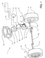
Figure 1 shows a schematic perspective view of a steering arrangement for a vehicle according to the present invention, -
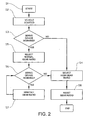
Figure 2 shows a flow chart that describes the method for a vehicle with a steering arrangement according to the present invention, and -
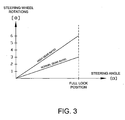
Figure 3 shows the steering angle as a function of the number of rotations of the steering wheel, with the servo device working and a normal gear ratio, and with the servo device not working and thus with a high gear ratio, according to the present invention. -
Figure 1 shows a schematic view of an example of asteering arrangement 1 for a heavy vehicle, for example in the form of a bus or a lorry. Thesteering arrangement 1 comprises asteering wheel 2 which is connected, via anupper steering column 3a, to avariable transmission 4 which, in turn, is connected, via alower steering column 3b, to asteering gear 5 of the worm gear type where thelower part 6 of thesteering column 3b is designed as a worm that is in engagement with a corresponding worm wheel on asteering shaft 7. Anarm 8 is arranged on thesteering shaft 7, which arm is, in turn, connected to arod 10 arranged between thewheels 9 of the vehicle, which rod 10 transfers movements of the steering wheel θ to movements of the wheels α via adrag link 11 and steeringarms 12. In addition, aservo device 13 driven by the vehicle's propulsion motor (not shown), in the form of a hydraulic pump, is connected to thesteering gear 5 viahydraulic pipes variable transmission 4 is carried out by a centralelectronic control unit 16, hereafter called an ECU, which sends a signal to the saidtransmission 4 in response to the function of the saidservo device 13, with the function, for example, being indicated by a pressure sensor for detecting the hydraulic pressure at the outlet of the hydraulic pump. Additional or alternative pressure sensors can also be arranged in other places in the hydraulic system in order, in this way, to give a good indication of the function of the servo device. In addition, in an electrical servo device, the speed and/or the power consumption of the electric motor can be used as an indicator of the function of the servo device. -
Figure 2 shows a schematic illustration of a flow chart that describes the vehicle steering gear ratio control method. The method starts S1 when the driver starts S2 the vehicle. The ECU detects S3 the function of the servo device. If the servo device is not working, the ECU selects S4 a high gear ratio by sending a signal to the variable transmission whereupon this is controlled so that a high gear ratio is obtained. By high gear ratio is meant here that the gear ratio is increased from a normal ratio by a factor in the range 1.2 to 3.5, preferably 1.25 to 2.25. If, however, the servo device is working, the ECU selects S5 a normal gear ratio in the said variable transmission. Thereafter, the ECU continually detects S6 the function of the servo device and maintains S7 the gear ratio as long as the servo device is working. If, for some reason, during operation, the servo device is no longer working, the ECU selects S4 a high gear ratio, as described above. Resetting of the gear ratio S8, after the servo device has not been working, is carried out after checks have been carried out in accordance with a predetermined routine. The method is thereby ended. -
Figure 3 shows examples of how the gear ratio affects the number of rotations of the steering wheel that are required between full lock positions. The lower line corresponds to a desired normal gear ratio where three rotations of the steering wheel are required between full lock positions, while the upper line shows a high gear ratio, in this case increased by a factor of two, which thus means that six rotations of the steering wheel are required in order to achieve the said movement between full lock positions. When, as described above, the gear ratio is varied in steps, this corresponds to lines (not shown) between the lines illustrated and when the gear ratio is varied steplessly, this corresponds to the area between the lines, that is to say the gear ratio can assume all values between the lines. - Other embodiments are also possible: For example, a steering gear of the rack and pinion type can be used instead of the steering gear of the worm gear type described above. In addition, the variable transmission can be integrated in said steering gear.
Claims (13)
- A vehicle steering gear ratio control method for a steering arrangement (1) comprising a steering element (2) connected to at least one wheel (9) of the vehicle, wherein a steering angle (α) of said wheel (9) of the vehicle being controlled in response to a movement (θ) of the steering element (2), wherein
said method includes the steps of:- detecting a function of a servo device (13, 14, 15) connected to the steering arrangement (1);- controlling a gear ratio between said movement (θ) of the steering element (2) and the steering angle (α) of the wheel (9) of the vehicle in response to the functioning of said servo device (13, 14, 15),characterized in that
said gear ratio is increased from a normal ratio to a higher ratio when reduced functioning of the servo device (13, 14, 15) is detected, and
said gear ratio is increased from said normal ratio to said higher ratio by a factor in a range of 1.25 to 2.25, when it is detected that the functioning of the servo device (13, 14, 15) has been reduced. - A vehicle steering gear ratio control method for a steering arrangement (1) as claimed in claim 1, characterized in that said gear ratio is increased in steps, preferably in at least three steps, from said normal ratio to said higher ratio.
- A vehicle steering gear ratio control method for a steering arrangement (1) as claimed in claim 1, characterized in that said control of the gear ratio is carried out steplessly, from said normal ratio to said higher ratio.
- A vehicle steering gear ratio control method for a steering arrangement (1) as claimed in any one of claims 1 to 3, characterized in that said gear ratio is increased by a factor corresponding to a detected reduction in functioning of the servo device (13, 14, 15) with a force that is applied to the steering element (2) in order to achieve a required steering angle (α) being compensated so that said force is less than a predetermined maximum level at which it is possible to continue to drive the vehicle.
- A vehicle steering gear ratio control method for a steering arrangement (1) as claimed in any one of the preceding claims, characterized in that said control of the gear ratio is carried out in a variable transmission (4).
- A vehicle steering gear ratio control method for a steering arrangement (1) as claimed in any one of the preceding claims, characterized in that the function of the servo device (13, 14, 15) is detected by detectioning of an oil pressure from a hydraulic pump comprised in the servo device (13,14,15).
- A vehicle steering gear ratio control method for a steering arrangement (1) as claimed in any one of the preceding claims, characterized in that said detection of functioning of the servo device (13, 14, 15) is carried out by detecting a speed of rotation of a shaft of an electric motor comprised in the servo device (13, 14, 15).
- A vehicle steering gear ratio control method for a steering arrangement (1) as claimed in any one of the preceding claims, characterized in that said detection of functioning of the servo device (13, 14, 15) is carried out by detecting a power consumption of an electric motor shaft comprised in the servo device (13, 14, 15).
- A vehicle steering gear ratio control method for a steering arrangement (1) as claimed in any one of the preceding claims, characterized in that the vehicle is a heavy vehicle, such as a bus or a lorry.
- A vehicle steering gear ratio control method for a steering arrangement (1) as claimed in any one of the preceding claims, characterized in that the steering clement (2) is a steering wheel.
- A computer program comprising program code for carrying out all the steps of a vehicle steering gear ratio control according to any one of claims 1-10 when said program is executed by a computer.
- A computer program product comprising program code stored on a medium that can be read by a computer, for carrying out all the steps of a vehicle steering gear ratio control according to any one of claims 1-10 when said computer program is executed by a computer.
- A computer program product that can be downloaded directly into an internal memory in a digital computer, comprising a computer program for carrying out all the steps of a vehicle steering gear ratio control according to any one of claims 1-10 when said computer program is executed by said computer.
Applications Claiming Priority (2)
| Application Number | Priority Date | Filing Date | Title |
|---|---|---|---|
| SE0303449A SE526240C2 (en) | 2003-12-17 | 2003-12-17 | Method and computer product of a control system of a vehicle |
| PCT/SE2004/001776 WO2005058670A1 (en) | 2003-12-17 | 2004-12-01 | Method and computer product in a steering arrangement for a vehicle |
Publications (2)
| Publication Number | Publication Date |
|---|---|
| EP1697201A1 EP1697201A1 (en) | 2006-09-06 |
| EP1697201B1 true EP1697201B1 (en) | 2009-05-06 |
Family
ID=30768768
Family Applications (1)
| Application Number | Title | Priority Date | Filing Date |
|---|---|---|---|
| EP04801699A Not-in-force EP1697201B1 (en) | 2003-12-17 | 2004-12-01 | Method and computer product in a steering arrangement for a vehicle |
Country Status (6)
| Country | Link |
|---|---|
| US (1) | US20060225947A1 (en) |
| EP (1) | EP1697201B1 (en) |
| AT (1) | ATE430679T1 (en) |
| DE (1) | DE602004021027D1 (en) |
| SE (1) | SE526240C2 (en) |
| WO (1) | WO2005058670A1 (en) |
Families Citing this family (6)
| Publication number | Priority date | Publication date | Assignee | Title |
|---|---|---|---|---|
| MX2008014783A (en) | 2008-02-05 | 2009-08-27 | Krueger Int Inc | Chair shell with integral hollow contoured support. |
| SE534469C2 (en) * | 2010-01-11 | 2011-09-06 | Scania Cv Ab | Device for active steering of a truck and steering device with such device |
| US9428209B2 (en) * | 2011-12-21 | 2016-08-30 | Toyota Jidosha Kabushiki Kaisha | Steering device |
| DE102013100187A1 (en) * | 2013-01-10 | 2014-07-10 | Zf Lenksysteme Gmbh | Steering system in a vehicle with electric servomotor |
| US20160200349A1 (en) * | 2015-01-09 | 2016-07-14 | Paccar Inc | Steering system having dual steering ratios |
| EP3533688B1 (en) * | 2016-12-05 | 2022-09-07 | Xuzhou Heavy Machinery Co., Ltd. | Active steering system for use in hoisting machinery, and hoisting machinery |
Family Cites Families (17)
| Publication number | Priority date | Publication date | Assignee | Title |
|---|---|---|---|---|
| JPS61166772A (en) * | 1985-01-21 | 1986-07-28 | Nissan Motor Co Ltd | Steering gear for vehicles |
| JP2694344B2 (en) * | 1988-06-17 | 1997-12-24 | 株式会社豊田中央研究所 | Vehicle steering angle control device |
| US4956590A (en) * | 1988-10-06 | 1990-09-11 | Techco Corporation | Vehicular power steering system |
| DE69007162T2 (en) * | 1989-05-17 | 1994-06-16 | Koyo Seiko Co | Motorized power steering device. |
| JP3211434B2 (en) * | 1991-12-18 | 2001-09-25 | アイシン精機株式会社 | Vehicle guidance control device |
| JP3257971B2 (en) * | 1997-09-12 | 2002-02-18 | 本田技研工業株式会社 | Electric power steering device |
| US6749040B1 (en) * | 1999-09-01 | 2004-06-15 | Delphi Technologies, Inc. | Electric power assisted rack and pinion system |
| JP3517833B2 (en) * | 2000-04-05 | 2004-04-12 | 本田技研工業株式会社 | Vehicle having variable steering angle ratio steering device and electric power steering device |
| US6520520B2 (en) * | 2000-10-31 | 2003-02-18 | Durrell U. Howard | Steering stabilizer with trimming accumulator |
| JP4419114B2 (en) * | 2000-11-14 | 2010-02-24 | 株式会社ジェイテクト | Vehicle steering system |
| US6655709B2 (en) * | 2002-01-29 | 2003-12-02 | Trw Inc. | Steer-by-wire steering apparatus with actuatable mechanism |
| DE60318919T2 (en) * | 2002-03-29 | 2009-01-29 | Advics Co., Ltd., Kariya | Vehicle control device with power steering |
| US7254470B2 (en) * | 2002-06-17 | 2007-08-07 | Delphi Technologies, Inc. | Fault tolerant torque sensor signal processing |
| JP4147836B2 (en) * | 2002-06-21 | 2008-09-10 | 株式会社ジェイテクト | Vehicle steering system |
| US7233850B2 (en) * | 2002-10-31 | 2007-06-19 | Koyo Seiko Co., Ltd. | Vehicle steering apparatus |
| US6804594B1 (en) * | 2003-03-28 | 2004-10-12 | Delphi Technologies, Inc. | Active steering for handling/stability enhancement |
| DE102004044729A1 (en) * | 2003-09-18 | 2005-04-21 | Hitachi Unisia Automotive Ltd | Power steering system |
-
2003
- 2003-12-17 SE SE0303449A patent/SE526240C2/en not_active IP Right Cessation
-
2004
- 2004-12-01 WO PCT/SE2004/001776 patent/WO2005058670A1/en not_active Application Discontinuation
- 2004-12-01 EP EP04801699A patent/EP1697201B1/en not_active Not-in-force
- 2004-12-01 DE DE602004021027T patent/DE602004021027D1/en active Active
- 2004-12-01 AT AT04801699T patent/ATE430679T1/en not_active IP Right Cessation
-
2006
- 2006-06-01 US US11/421,681 patent/US20060225947A1/en not_active Abandoned
Also Published As
| Publication number | Publication date |
|---|---|
| DE602004021027D1 (en) | 2009-06-18 |
| SE526240C2 (en) | 2005-08-02 |
| SE0303449D0 (en) | 2003-12-17 |
| SE0303449L (en) | 2005-06-18 |
| EP1697201A1 (en) | 2006-09-06 |
| US20060225947A1 (en) | 2006-10-12 |
| ATE430679T1 (en) | 2009-05-15 |
| WO2005058670A1 (en) | 2005-06-30 |
Similar Documents
| Publication | Publication Date | Title |
|---|---|---|
| US5992556A (en) | Method and apparatus for damping control of an electric assist steering system with vehicle speed signal loss feature | |
| US4909343A (en) | Electric power steering system | |
| US7322439B2 (en) | Steering apparatus for steerable vehicle | |
| US6705420B2 (en) | Steering angle ratio control system and method | |
| EP0858942B1 (en) | Steering apparatus for vehicle | |
| US8428822B2 (en) | Method of determining a steering angle in a motor vehicle | |
| EP1481874A2 (en) | Steering apparatus and method for automotive vehicle | |
| US20060225947A1 (en) | Method and computer product in a steering arrangement for a vehicle | |
| JP2525494B2 (en) | Power steering device for automobile | |
| JP4485802B2 (en) | Hydraulic servo steering device | |
| JP3935970B2 (en) | Power steering device with hydraulic power assist mechanism | |
| JPH09156526A (en) | Steering control device for vehicle | |
| US6474437B1 (en) | Power-assisted steering with hydraulic power assistance | |
| KR100192381B1 (en) | Power steering system for vehicles | |
| JP2005532218A (en) | Hydraulic power steering system | |
| US7882925B2 (en) | Vehicle steering apparatus | |
| JP6125534B2 (en) | Power steering apparatus having an angle difference sensor | |
| US8781683B2 (en) | Power steering apparatus and method | |
| US9545948B2 (en) | Hydraulically assisted power steering system | |
| US10071760B2 (en) | Adaptive front steering system for vehicle | |
| CN101827742A (en) | The power steering gear that is used for vehicle | |
| US20190270480A1 (en) | Apparatus and method for turning steerable vehicle wheels | |
| KR101104512B1 (en) | Method and Device for Controlling Rackbar Stroke with Detecting Switch of Snowchain and ECU Therefor | |
| CN1232420C (en) | Electric steering system with mechanical back-up device | |
| JP3613691B2 (en) | Vehicle steering system |
Legal Events
| Date | Code | Title | Description |
|---|---|---|---|
| PUAI | Public reference made under article 153(3) epc to a published international application that has entered the european phase |
Free format text: ORIGINAL CODE: 0009012 |
|
| 17P | Request for examination filed |
Effective date: 20060717 |
|
| AK | Designated contracting states |
Kind code of ref document: A1 Designated state(s): AT BE BG CH CY CZ DE DK EE ES FI FR GB GR HU IE IS IT LI LT LU MC NL PL PT RO SE SI SK TR |
|
| 17Q | First examination report despatched |
Effective date: 20061207 |
|
| DAX | Request for extension of the european patent (deleted) | ||
| GRAP | Despatch of communication of intention to grant a patent |
Free format text: ORIGINAL CODE: EPIDOSNIGR1 |
|
| GRAS | Grant fee paid |
Free format text: ORIGINAL CODE: EPIDOSNIGR3 |
|
| GRAA | (expected) grant |
Free format text: ORIGINAL CODE: 0009210 |
|
| AK | Designated contracting states |
Kind code of ref document: B1 Designated state(s): AT BE BG CH CY CZ DE DK EE ES FI FR GB GR HU IE IS IT LI LT LU MC NL PL PT RO SE SI SK TR |
|
| REG | Reference to a national code |
Ref country code: GB Ref legal event code: FG4D |
|
| REG | Reference to a national code |
Ref country code: CH Ref legal event code: EP |
|
| REG | Reference to a national code |
Ref country code: IE Ref legal event code: FG4D |
|
| REF | Corresponds to: |
Ref document number: 602004021027 Country of ref document: DE Date of ref document: 20090618 Kind code of ref document: P |
|
| PG25 | Lapsed in a contracting state [announced via postgrant information from national office to epo] |
Ref country code: ES Free format text: LAPSE BECAUSE OF FAILURE TO SUBMIT A TRANSLATION OF THE DESCRIPTION OR TO PAY THE FEE WITHIN THE PRESCRIBED TIME-LIMIT Effective date: 20090817 Ref country code: AT Free format text: LAPSE BECAUSE OF FAILURE TO SUBMIT A TRANSLATION OF THE DESCRIPTION OR TO PAY THE FEE WITHIN THE PRESCRIBED TIME-LIMIT Effective date: 20090506 Ref country code: PT Free format text: LAPSE BECAUSE OF FAILURE TO SUBMIT A TRANSLATION OF THE DESCRIPTION OR TO PAY THE FEE WITHIN THE PRESCRIBED TIME-LIMIT Effective date: 20090906 Ref country code: LT Free format text: LAPSE BECAUSE OF FAILURE TO SUBMIT A TRANSLATION OF THE DESCRIPTION OR TO PAY THE FEE WITHIN THE PRESCRIBED TIME-LIMIT Effective date: 20090506 Ref country code: FI Free format text: LAPSE BECAUSE OF FAILURE TO SUBMIT A TRANSLATION OF THE DESCRIPTION OR TO PAY THE FEE WITHIN THE PRESCRIBED TIME-LIMIT Effective date: 20090506 |
|
| NLV1 | Nl: lapsed or annulled due to failure to fulfill the requirements of art. 29p and 29m of the patents act | ||
| PG25 | Lapsed in a contracting state [announced via postgrant information from national office to epo] |
Ref country code: SI Free format text: LAPSE BECAUSE OF FAILURE TO SUBMIT A TRANSLATION OF THE DESCRIPTION OR TO PAY THE FEE WITHIN THE PRESCRIBED TIME-LIMIT Effective date: 20090506 Ref country code: SE Free format text: LAPSE BECAUSE OF FAILURE TO SUBMIT A TRANSLATION OF THE DESCRIPTION OR TO PAY THE FEE WITHIN THE PRESCRIBED TIME-LIMIT Effective date: 20090806 Ref country code: PL Free format text: LAPSE BECAUSE OF FAILURE TO SUBMIT A TRANSLATION OF THE DESCRIPTION OR TO PAY THE FEE WITHIN THE PRESCRIBED TIME-LIMIT Effective date: 20090506 Ref country code: NL Free format text: LAPSE BECAUSE OF FAILURE TO SUBMIT A TRANSLATION OF THE DESCRIPTION OR TO PAY THE FEE WITHIN THE PRESCRIBED TIME-LIMIT Effective date: 20090506 Ref country code: IS Free format text: LAPSE BECAUSE OF FAILURE TO SUBMIT A TRANSLATION OF THE DESCRIPTION OR TO PAY THE FEE WITHIN THE PRESCRIBED TIME-LIMIT Effective date: 20090906 |
|
| PG25 | Lapsed in a contracting state [announced via postgrant information from national office to epo] |
Ref country code: RO Free format text: LAPSE BECAUSE OF FAILURE TO SUBMIT A TRANSLATION OF THE DESCRIPTION OR TO PAY THE FEE WITHIN THE PRESCRIBED TIME-LIMIT Effective date: 20090506 Ref country code: CZ Free format text: LAPSE BECAUSE OF FAILURE TO SUBMIT A TRANSLATION OF THE DESCRIPTION OR TO PAY THE FEE WITHIN THE PRESCRIBED TIME-LIMIT Effective date: 20090506 Ref country code: EE Free format text: LAPSE BECAUSE OF FAILURE TO SUBMIT A TRANSLATION OF THE DESCRIPTION OR TO PAY THE FEE WITHIN THE PRESCRIBED TIME-LIMIT Effective date: 20090506 Ref country code: DK Free format text: LAPSE BECAUSE OF FAILURE TO SUBMIT A TRANSLATION OF THE DESCRIPTION OR TO PAY THE FEE WITHIN THE PRESCRIBED TIME-LIMIT Effective date: 20090506 |
|
| PG25 | Lapsed in a contracting state [announced via postgrant information from national office to epo] |
Ref country code: SK Free format text: LAPSE BECAUSE OF FAILURE TO SUBMIT A TRANSLATION OF THE DESCRIPTION OR TO PAY THE FEE WITHIN THE PRESCRIBED TIME-LIMIT Effective date: 20090506 Ref country code: BE Free format text: LAPSE BECAUSE OF FAILURE TO SUBMIT A TRANSLATION OF THE DESCRIPTION OR TO PAY THE FEE WITHIN THE PRESCRIBED TIME-LIMIT Effective date: 20090506 |
|
| PLBE | No opposition filed within time limit |
Free format text: ORIGINAL CODE: 0009261 |
|
| STAA | Information on the status of an ep patent application or granted ep patent |
Free format text: STATUS: NO OPPOSITION FILED WITHIN TIME LIMIT |
|
| PG25 | Lapsed in a contracting state [announced via postgrant information from national office to epo] |
Ref country code: BG Free format text: LAPSE BECAUSE OF FAILURE TO SUBMIT A TRANSLATION OF THE DESCRIPTION OR TO PAY THE FEE WITHIN THE PRESCRIBED TIME-LIMIT Effective date: 20090806 |
|
| 26N | No opposition filed |
Effective date: 20100209 |
|
| PG25 | Lapsed in a contracting state [announced via postgrant information from national office to epo] |
Ref country code: MC Free format text: LAPSE BECAUSE OF NON-PAYMENT OF DUE FEES Effective date: 20100701 |
|
| REG | Reference to a national code |
Ref country code: CH Ref legal event code: PL |
|
| REG | Reference to a national code |
Ref country code: IE Ref legal event code: MM4A |
|
| PG25 | Lapsed in a contracting state [announced via postgrant information from national office to epo] |
Ref country code: LI Free format text: LAPSE BECAUSE OF NON-PAYMENT OF DUE FEES Effective date: 20091231 Ref country code: CH Free format text: LAPSE BECAUSE OF NON-PAYMENT OF DUE FEES Effective date: 20091231 Ref country code: GR Free format text: LAPSE BECAUSE OF FAILURE TO SUBMIT A TRANSLATION OF THE DESCRIPTION OR TO PAY THE FEE WITHIN THE PRESCRIBED TIME-LIMIT Effective date: 20090807 Ref country code: IE Free format text: LAPSE BECAUSE OF NON-PAYMENT OF DUE FEES Effective date: 20091201 |
|
| PG25 | Lapsed in a contracting state [announced via postgrant information from national office to epo] |
Ref country code: LU Free format text: LAPSE BECAUSE OF NON-PAYMENT OF DUE FEES Effective date: 20091201 |
|
| PG25 | Lapsed in a contracting state [announced via postgrant information from national office to epo] |
Ref country code: HU Free format text: LAPSE BECAUSE OF FAILURE TO SUBMIT A TRANSLATION OF THE DESCRIPTION OR TO PAY THE FEE WITHIN THE PRESCRIBED TIME-LIMIT Effective date: 20091107 |
|
| PG25 | Lapsed in a contracting state [announced via postgrant information from national office to epo] |
Ref country code: TR Free format text: LAPSE BECAUSE OF FAILURE TO SUBMIT A TRANSLATION OF THE DESCRIPTION OR TO PAY THE FEE WITHIN THE PRESCRIBED TIME-LIMIT Effective date: 20090506 |
|
| PG25 | Lapsed in a contracting state [announced via postgrant information from national office to epo] |
Ref country code: CY Free format text: LAPSE BECAUSE OF FAILURE TO SUBMIT A TRANSLATION OF THE DESCRIPTION OR TO PAY THE FEE WITHIN THE PRESCRIBED TIME-LIMIT Effective date: 20090506 |
|
| PGFP | Annual fee paid to national office [announced via postgrant information from national office to epo] |
Ref country code: GB Payment date: 20131127 Year of fee payment: 10 |
|
| PGFP | Annual fee paid to national office [announced via postgrant information from national office to epo] |
Ref country code: IT Payment date: 20131210 Year of fee payment: 10 Ref country code: FR Payment date: 20131209 Year of fee payment: 10 |
|
| GBPC | Gb: european patent ceased through non-payment of renewal fee |
Effective date: 20141201 |
|
| REG | Reference to a national code |
Ref country code: FR Ref legal event code: ST Effective date: 20150831 |
|
| PG25 | Lapsed in a contracting state [announced via postgrant information from national office to epo] |
Ref country code: GB Free format text: LAPSE BECAUSE OF NON-PAYMENT OF DUE FEES Effective date: 20141201 |
|
| PG25 | Lapsed in a contracting state [announced via postgrant information from national office to epo] |
Ref country code: FR Free format text: LAPSE BECAUSE OF NON-PAYMENT OF DUE FEES Effective date: 20141231 |
|
| PG25 | Lapsed in a contracting state [announced via postgrant information from national office to epo] |
Ref country code: IT Free format text: LAPSE BECAUSE OF NON-PAYMENT OF DUE FEES Effective date: 20141201 |
|
| PGFP | Annual fee paid to national office [announced via postgrant information from national office to epo] |
Ref country code: DE Payment date: 20191230 Year of fee payment: 16 |
|
| REG | Reference to a national code |
Ref country code: DE Ref legal event code: R119 Ref document number: 602004021027 Country of ref document: DE |
|
| PG25 | Lapsed in a contracting state [announced via postgrant information from national office to epo] |
Ref country code: DE Free format text: LAPSE BECAUSE OF NON-PAYMENT OF DUE FEES Effective date: 20210701 |