EP1696152B1 - Continously varialble transmission - Google Patents
Continously varialble transmission Download PDFInfo
- Publication number
- EP1696152B1 EP1696152B1 EP06110299A EP06110299A EP1696152B1 EP 1696152 B1 EP1696152 B1 EP 1696152B1 EP 06110299 A EP06110299 A EP 06110299A EP 06110299 A EP06110299 A EP 06110299A EP 1696152 B1 EP1696152 B1 EP 1696152B1
- Authority
- EP
- European Patent Office
- Prior art keywords
- carrier
- gear
- planetary gear
- continuously variable
- sun gear
- Prior art date
- Legal status (The legal status is an assumption and is not a legal conclusion. Google has not performed a legal analysis and makes no representation as to the accuracy of the status listed.)
- Not-in-force
Links
- 230000005540 biological transmission Effects 0.000 title claims description 62
- 230000007246 mechanism Effects 0.000 claims description 109
- 238000010586 diagram Methods 0.000 description 7
- 230000007935 neutral effect Effects 0.000 description 6
- 238000005452 bending Methods 0.000 description 4
- 230000007423 decrease Effects 0.000 description 2
- 230000001133 acceleration Effects 0.000 description 1
- 230000003247 decreasing effect Effects 0.000 description 1
- 238000005516 engineering process Methods 0.000 description 1
- 238000003466 welding Methods 0.000 description 1
Images


Classifications
-
- F—MECHANICAL ENGINEERING; LIGHTING; HEATING; WEAPONS; BLASTING
- F16—ENGINEERING ELEMENTS AND UNITS; GENERAL MEASURES FOR PRODUCING AND MAINTAINING EFFECTIVE FUNCTIONING OF MACHINES OR INSTALLATIONS; THERMAL INSULATION IN GENERAL
- F16H—GEARING
- F16H37/00—Combinations of mechanical gearings, not provided for in groups F16H1/00 - F16H35/00
- F16H37/02—Combinations of mechanical gearings, not provided for in groups F16H1/00 - F16H35/00 comprising essentially only toothed or friction gearings
- F16H37/06—Combinations of mechanical gearings, not provided for in groups F16H1/00 - F16H35/00 comprising essentially only toothed or friction gearings with a plurality of driving or driven shafts; with arrangements for dividing torque between two or more intermediate shafts
- F16H37/08—Combinations of mechanical gearings, not provided for in groups F16H1/00 - F16H35/00 comprising essentially only toothed or friction gearings with a plurality of driving or driven shafts; with arrangements for dividing torque between two or more intermediate shafts with differential gearing
- F16H37/0833—Combinations of mechanical gearings, not provided for in groups F16H1/00 - F16H35/00 comprising essentially only toothed or friction gearings with a plurality of driving or driven shafts; with arrangements for dividing torque between two or more intermediate shafts with differential gearing with arrangements for dividing torque between two or more intermediate shafts, i.e. with two or more internal power paths
- F16H37/084—Combinations of mechanical gearings, not provided for in groups F16H1/00 - F16H35/00 comprising essentially only toothed or friction gearings with a plurality of driving or driven shafts; with arrangements for dividing torque between two or more intermediate shafts with differential gearing with arrangements for dividing torque between two or more intermediate shafts, i.e. with two or more internal power paths at least one power path being a continuously variable transmission, i.e. CVT
- F16H37/086—CVT using two coaxial friction members cooperating with at least one intermediate friction member
-
- F—MECHANICAL ENGINEERING; LIGHTING; HEATING; WEAPONS; BLASTING
- F16—ENGINEERING ELEMENTS AND UNITS; GENERAL MEASURES FOR PRODUCING AND MAINTAINING EFFECTIVE FUNCTIONING OF MACHINES OR INSTALLATIONS; THERMAL INSULATION IN GENERAL
- F16H—GEARING
- F16H37/00—Combinations of mechanical gearings, not provided for in groups F16H1/00 - F16H35/00
- F16H37/02—Combinations of mechanical gearings, not provided for in groups F16H1/00 - F16H35/00 comprising essentially only toothed or friction gearings
- F16H37/06—Combinations of mechanical gearings, not provided for in groups F16H1/00 - F16H35/00 comprising essentially only toothed or friction gearings with a plurality of driving or driven shafts; with arrangements for dividing torque between two or more intermediate shafts
- F16H37/08—Combinations of mechanical gearings, not provided for in groups F16H1/00 - F16H35/00 comprising essentially only toothed or friction gearings with a plurality of driving or driven shafts; with arrangements for dividing torque between two or more intermediate shafts with differential gearing
- F16H37/0833—Combinations of mechanical gearings, not provided for in groups F16H1/00 - F16H35/00 comprising essentially only toothed or friction gearings with a plurality of driving or driven shafts; with arrangements for dividing torque between two or more intermediate shafts with differential gearing with arrangements for dividing torque between two or more intermediate shafts, i.e. with two or more internal power paths
- F16H37/084—Combinations of mechanical gearings, not provided for in groups F16H1/00 - F16H35/00 comprising essentially only toothed or friction gearings with a plurality of driving or driven shafts; with arrangements for dividing torque between two or more intermediate shafts with differential gearing with arrangements for dividing torque between two or more intermediate shafts, i.e. with two or more internal power paths at least one power path being a continuously variable transmission, i.e. CVT
- F16H2037/088—Power split variators with summing differentials, with the input of the CVT connected or connectable to the input shaft
- F16H2037/0886—Power split variators with summing differentials, with the input of the CVT connected or connectable to the input shaft with switching means, e.g. to change ranges
Definitions
- the present invention relates to a continuously variable transmission which is able to obtain a wide range of output speed ratios compared with the speed ratios of a continuously variable speed-change unit, by combining a toroidal-type continuously variable speed change unit and a planetary gear mechanism and using torque circulation. More specifically, the present invention relates to a continuously variable transmission in which an input shaft and an output shaft are arranged on the same axis.
- this continuously variable transmission 1 includes a toroidal-type continuously variable speed change unit 5, a planetary gear mechanism 6, a counter gear mechanism 7, and a Low/High switching mechanism 10, all of which are arranged on a single axis between an input shaft 12 and an output shaft 13.
- the toroidal-type continuously variable speed change unit 5 includes input discs 2 and an output disc 3, as well as rollers 4 arranged between these discs such that the radial position of contact with the discs can be changed.
- the planetary gear mechanism 6 has a carrier C1 on which three pinions P1, P2, P3 are arranged in the axial direction.
- the counter gear mechanism 7 has a carrier C2 on which two pinions P4, P5 are arranged in the axial direction.
- the Low/High switching mechanism 10 includes a Low brake L that can hold an output side sun gear S4 of the counter gear mechanism against rotation, and a High clutch H interposed between a second sun gear (i.e., a High mode output gear) S2 of the planetary gear and the output shaft 13.
- the Low/High switching mechanism 10 may alternatively include a Low clutch L interposed between the carrier C2 and the output shaft 13, as shown in FIG. 6(b) , and a High clutch H interposed between the second sun gear S2 of the planetary gear and the output shaft 13 like that described above.
- this continuously variable transmission 1 1 includes a toroidal-type continuously variable speed change unit 5 and a planetary gear mechanism 6, which are similar to those described above, and a counter gear mechanism 7 1 which is a double pinion planetary gear. That is, a carrier C0 rotatably supports pinions P4, P5 which are in mesh with each other, while one pinion P4 is in mesh with a sun gear S0 and the other pinion P5 is in mesh with a ring gear R0.
- the sun gear S0 is connected to the third sun gear (i.e., the Low mode output gear) S3 of the planetary gear mechanism 6, the ring gear R0 is fixed to a case 15, and the carrier C0 is coupled to the output shaft 13 via the Low clutch L.
- the third sun gear i.e., the Low mode output gear
- the ring gear R0 is fixed to a case 15
- the carrier C0 is coupled to the output shaft 13 via the Low clutch L.
- This continuously variable transmission 1 1 operates as illustrated in the velocity diagram of FIG. 8 . That is, in a Low mode in which the Low clutch L is applied and the High clutch H is released, rotation of the input shaft 12 (e.g., engine output rotation) is transmitted to the carrier C1 of the planetary gear mechanism 6 via a hollow shaft 12a as well as reversed and transmitted to a first sun gear (i.e., an input gear) S1 via a toroidal-type continuously variable speed change unit (variator) 5. The rotation input to the carrier C 1 and the reversed speed-changed rotation of the input gear S 1 are combined while torque is circulated at the planetary gear mechanism 6, and then output from the third sun gear (i.e., the Low mode side output gear) S3.
- the third sun gear i.e., the Low mode side output gear
- the rotation of the output gear S3 is transmitted to the input sun gear S0 of the counter gear mechanism 7 1 , which is integrated with the output gear S3. That rotation is then reversed because the ring gear R0 is stationary, and output from the carrier C0. The rotation of the carrier C0 is then transmitted to the output shaft 13 via the Low clutch L which is applied. Therefore, the reverse rotation of the output gear S3 becomes forward rotation at the carrier C0 and the output shaft 13.
- another counter mechanism not shown, is provided in a differential mechanism on the downstream side in the transmission path of the continuously variable transmission 1 1 so the forward rotation of the output shaft 13 actually becomes reverse rotation output for the vehicle. That is, when the variator 5 changes from OD to UD, the output shaft (i.e., the carrier C0) 13 passes through the GN point (i.e., zero rotation) and shifts to forward rotation.
- the mode switches from Low mode to High mode when the Low clutch L is released and the High clutch H is applied.
- rotation of the second sun gear (i.e., the High mode output gear) S2 of the planetary gear mechanism 6 is output directly from the output shaft 13 via the High clutch H.
- rotation of the input shaft 12 is directly transmitted to the carrier C1 of the planetary gear mechanism 6, as well as reversed and transmitted to the first sun gear (i.e., the input gear) S1 via the toroidal-type continuously variable speed change unit (variator) 5.
- the forward rotation of the carrier C1 is combined with the reversed speed-changed rotation of the first sun gear S 1 at the planetary gear mechanism 6, and that combined rotation is output from the second sun gear S2.
- the input side gear ratio (S 1 / P1) and the output side gear ratio (S2 / P2) are values that are close or the same so an output speed is obtained in which the speed ratio (i.e., the gear ratio) of the variator 5 is off in the reverse direction by a value that substantially corresponds to the forward output speed at maximum UD of the variator 5 in the Low mode. That is, when the variator 5 is at maximum UD, the second sun gear (i.e., the output gear) S2 is at the lowest forward output speed in the High mode. As the variator 5 shifts from the UD side to the OD side, that forward output speed increases.
- the reverse rotation here actually results in forward rotation with respect to the output of the vehicle because of the other counter mechanism.
- the continuously variable transmission 1 1 shown in FIG. 7 described above is reduced in length in the axial direction by using a double pinion planetary gear in the counter gear mechanism.
- the planetary gear mechanism 6 for combining torque is configured such that three pinions are aligned in the axial direction (i.e., a three-step pinion), just like the continuously variable transmission 1 disclosed in Patent Document 1 described above (see FIG. 6 ).
- the planetary gear mechanism 6 has the carrier C1 which serially supports, in the axial direction, the three pinions P1, P2, P3, a first sun gear (i.e., the input gear) S1 which is in mesh with the first pinion P1, a second sun gear (i.e., the High mode output gear) S2 which is in mesh with the second pinion P2, and a third sun gear (i.e., the Low mode output gear) S3 which is in mesh with the third pinion P3.
- a first sun gear i.e., the input gear
- S2 which is in mesh with the first pinion P1
- a second sun gear i.e., the High mode output gear
- S3 which is in mesh with the third pinion P3.
- the carrier C1 has a carrier main body 21 a, which is formed integrally with one of the discs 2 of the toroidal-type continuously variable speed change unit (i.e., the variator 5), and a carrier cover 21b which is integrally formed with the carrier main body 21a.
- the carrier main body 21a is rotatably supported by a transmission case 22 via a bearing 24.
- a pinion shaft 23 is provided on the carrier main body 21a and the cover 21b.
- the first, second, and third pinions P1, P2, P3, which are integrally formed, are rotatably supported via either a needle bearing 29 or a bush on the shaft 23.
- a bush is also included in the concept of a bearing.
- the first sun gear S1 is formed at an end portion of a hollow shaft 25, the base portion of which is coupled to the central output disc 3 of the variator 5 (see FIGS. 6 and 7 ).
- An input shaft (core shaft) 12 is rotatably supported via a needle bearing or the like in the hollow portion of the hollow shaft 25.
- the base portion (toward the front of the vehicle) of this input shaft 12 is coupled to an engine output shaft via a damper, while the end portion (toward the rear of the vehicle) of the input shaft 12 is spline-engaged to the carrier main body 21a.
- the second sun gear S2 is formed on an intermediate shaft 26 which is connected to the High clutch H of the Low/High switching mechanism (see FIGS. 6 and 7 ).
- the third sun gear S3 is formed on a sleeve 27 which is rotatably fitted around the intermediate shaft 26. This sleeve 27 is connected to the sun gear S0 of the counter gear mechanism 7 (see FIGS. 6 and 7 ).
- the pinion shaft 23 supports all three pinions P1, P2, P3 which are integrally formed serially in the axial direction makes the pinion shaft 23 long in the axial direction, and as described above, because it makes up an IVT (infinitely variable transmission) with torque circulation, i.e., because it performs continuously shifting with the highest forward output speed in the Low mode approximately matching the lowest forward output speed in High mode when the variator 5 is at maximum UD, the gear diameter of the third pinion P3 is smaller, which means the diameter of the pinion shaft 23 also has to be smaller.
- IVT infinitetely variable transmission
- the diameter of the bearing 29 is also smaller, which means the bearing will have a shorter life span.
- the reduced diameter of the pinion shaft renders the pinion shaft insufficiently rigid, making it susceptible to bending which would increase the load on the bearing. The combination of these factors may result in insufficient precision and life span of the carrier C1.
- the three pinions P1, P2, P3 which are formed integral with one another are heavy, which results in a large centrifugal load acting on the carrier C1.
- the structure of the planetary gear mechanism 6 is disadvantageous also with respect to loads such as this centrifugal load.
- the planetary gear mechanism 6 is long in the axial direction such that even if the counter gear mechanism were shortened, the transmission would still be long in the axial direction for a continuously variable transmission.
- the present invention provides a continuously variable transmission which includes the planetary gear mechanism includes a two-step pinion and a simple planetary gear.
- the pinion shaft is short but long enough to support two rows of pinions in the axial direction.
- the bearing which rotatably supports the two rows of pinions can be large in diameter, which increases the length of the bearing life span and reduces bending of the pinion shaft and thus the load fluctuation on the bearing that results from that bending.
- the pinion weight is lightened such that the load caused by the centrifugal load is reduced. The combination of these factors improves the precision with which the pinion is supported and enables that high precision to be maintained over an extended period of time.
- the input shaft and the input disc of the toroidal speed change unit may be connected to the first carrier, the output disc of the toroidal speed change unit may be connected to the first sun gear, and the center portion of the toroidal speed change unit may be configured by two heavy shafts, thus resulting in compact and logical connective relationships.
- the present invention further provides a continuously variable transmission which includes the planetary gear mechanism such that the first carrier is connected to the ring gear of the simple planetary gear and the second sun gear is connected to the sun gear of the simple planetary gear.
- a continuously variable transmission which includes the planetary gear mechanism such that the first carrier is connected to the ring gear of the simple planetary gear and the second sun gear is connected to the sun gear of the simple planetary gear.
- the counter gear mechanism may include a double pinion planetary gear.
- the counter gear mechanism can be made shorter in the axial direction, thus making the continuously variable transmission even more compact, enabling it to be shorter in the axial direction in particular.
- the carrier of the single planetary gear of the planetary gear mechanism may be formed integral with the carrier of the counter gear mechanism.
- the planetary gear mechanism and the counter gear mechanism are inseparably connected together so as to form an overall compact and simple mechanism, thus enabling the continuously variable transmission to be more compact and reliable.
- the toroidal-type continuously variable speed change unit which receives a large force (thrust) in the axial direction, including the input shaft which is substantially integral with the input disc of the toroidal-type continuously variable speed change unit and the carrier of the planetary gear mechanism, may be supported such that thrust is cancelled out.
- the continuously variable speed change unit and the first and second sun gears may be supported such that thrust, including the thrust that acts on the first and second sun gears, is cancelled out.
- the toroidal-type continuously variable speed change unit and the planetary gear mechanism are supported as a single system such that thrust is cancelled out, which enables highly precise support to be maintained over an extended period of time, thus increasing the length of life of the continuously variable transmission.
- the thrust generated in the planetary gear mechanism caused by the helical gears acts to cancel itself out in the planetary gear mechanism by the first thrust bearing interposed between the first sun gear and the first carrier and the second thrust bearing interposed between the first carrier and the sun gear of the simple planetary gear. Therefore, for example, it is no longer necessary to provide a thrust bearing between the first carrier and the second sun gear so the number of thrust bearings can be reduced, and the continuously variable transmission can be made more compact in the axial direction.
- FIGS. 1 to 5 An example embodiment of the present invention will be described with reference to FIGS. 1 to 5 .
- An infinitely variable transmission (IVT) 1 2 includes a continuously variable speed change unit (variator) 5, a planetary gear mechanism 6 1 , a counter gear mechanism 7 1 , and a Low/High switching mechanism 10, as shown in FIG. 1 .
- the continuously variable speed change unit 5 is a full toroidal-type continuously variable speed change unit and includes two input discs 2, 2 connected to an input shaft 12, one output disc 3 connected to a hollow shaft 25, and power rollers 4, 4 that are sandwiched between the input discs and the output disc.
- the input discs 2 and the output disc 3 have arc-shaped concave grooves 2a, 3a that form part of a circle and which face each other so as to form two cavities that sandwich two rows of power rollers, such that the thrust from one of the input discs is cancelled out by the thrust from the other input disc.
- the power rollers 4, 4 are tilted by shifting them in a direction perpendicular to the shaft, and shifting is performed continuously and steplessly by changing the contact radius of the input discs 2 and the output disc 3.
- This variator 5 has a speed ratio (i.e., output speed / input speed) of -0.4 to -2.5. The speed ratio is negative (minus) because the output disc 3 rotates in the opposite direction from the input discs 2.
- the planetary gear mechanism 6 1 includes a front carrier (i.e., a first carrier) C which has two pinions P1, P2, and a Low mode simple planetary gear 11.
- This Low mode simple planetary gear 11 includes a rear carrier C0 which is in common with a double pinion planetary gear 14 of the counter gear mechanism 7 1 .
- the two pinions (i.e., the first pinion and the second pinion) P1, P2 are integrally formed and are rotatably supported on a common pinion shaft.
- the front carrier C which supports these pinions is connected to a ring gear R3 of the Low mode simple planetary gear 11.
- the front carrier C is connected to the input shaft 12 as well as to one of the input discs 2, so rotation of the input shaft 12 is transmitted.
- the first pinion P 1 is in mesh with the first sun gear S 1 that is connected to the output disc 3 of the variator 5.
- This first sun gear S 1 serves as an input gear into which speed-changed rotation from the variator 5 is input.
- the second pinion P2 is in mesh with the second sun gear S2 which serves as a High mode output gear.
- the second pinion P2 is also integrally connected to a (third) sun gear S3 of the Low mode simple planetary gear 11.
- These second and third sun gears S2, S3 are both connected to the output shaft 13 via a High clutch H of the Low/High switching mechanism 10 and thus serve as High mode output gears.
- the counter gear mechanism 7 1 includes a double pinion planetary gear 14 that has two pinions (a fourth pinion P4 and a fifth pinion P5) which are in mesh with each other.
- the carrier C0 of the double pinion planetary gear 14 is also integrally formed with the carrier of the Low mode simple planetary gear 11, as described above.
- a (second) ring gear R0 is fixed to a case 22, and a (fourth) sun gear S0 is connected to the output shaft 13 via a Low clutch L.
- This infinitely variable transmission (IVT) 1 2 operates as illustrated in the velocity diagram in FIG. 2 .
- the first and second pinions P1, P2 are common long pinions, the gear ratios S1 / P1 and S2 / P2 are changed, and the output speed and the variator output line do not overlap.
- the gear ratios (S 1 / P1) (S2 / P2) may be the same and the output speed and the variator output line may of course overlap.
- the output carrier C0 changes from reverse rotation to the gear neutral position (GN point), i.e., a position in which the output speed becomes zero and torque is endlessly released.
- GN point gear neutral position
- rotation of the output carrier C0 accelerates in the forward direction (i.e., the same direction as that in which the input shaft rotates).
- the rotation of the output carrier C0 is directly transmitted to the carrier of the counter gear mechanism 7 1 , which is a common carrier. This rotation is then reversed because the ring gear R0 is held stationary, and output from the sun gear S0. As a result, the rotation of the output carrier C0 is reversed. Reverse rotation of the output carrier C0 is output as a reverse output speed to the sun gear S0 and forward rotation of the output carrier C0 is output as a forward output speed to the sun gear S0.
- the mode switches from Low mode to High mode when the Low clutch L is released and the High clutch H is applied.
- rotation of the input shaft 12 is directly transmitted to the front carrier C of the planetary gear mechanism 6 1 , while reversed speed-changed rotation is transmitted to the first sun gear S1 from the variator 5.
- These two rotations are then combined by the planetary gear mechanism 6 1 and output from the second sun gear S2 which serves as the High mode output gear.
- the sun gear S0 and the carrier C0 of the counter gear mechanism 7 1 rotate idly because the Low clutch L is released. Therefore the ring gear R3 of the planetary gear mechanism 6 1 also rotates idly.
- the gear ratios S1 / P1 and S2 / P2 have close or the same values, so a rotation that is close to or the same as the speed-changed output rotation from the variator 5 (i.e., the variator gear ratio) is output from the second sun gear S2, and the variator gear ratio is output as a High mode forward output speed from the output shaft 13 because the High clutch H is applied.
- the speed ratio of the IVT 1 2 continuously accelerates in the reverse direction (i.e., the negative direction).
- the speed ratio of the IVT 1 2 is approximately -0.5.
- the mode switches to the High mode.
- the speed ratio of the variator 5 is at the UD end in the High mode, the speed ratio of the IVT 1 2 is the same value (i.e., approximately -0.5) that it was in the Low mode.
- the speed ratio of the IVT 1 2 accelerates continuously in the reverse direction (i.e., the negative direction) from the Low mode. The acceleration in the reverse direction continues as the variator 5 shifts farther toward OD.
- the speed ratio of the variator 5 reaches the OD end (approximately -2.5), the speed ratio of the IVT 1 2 is approximately -2.75 which is the maximum speed ratio.
- the direction of rotation of the input shaft 12 i.e., the direction of engine rotation
- the speed ratio is denoted with a plus sign.
- the variator 5 rotates in reverse due to the toroidal system, so the speed ratio thereof is negative.
- this infinitely variable transmission (IVT) 1 2 is used in a vehicle where rotation is reversed again by a counter gear in a differential mechanism, the vehicle travels in reverse when the speed ratio of the IVT 1 2 is positive, and forward when the speed ratio is negative.
- the variator 5 shifts from the OD end toward UD in the Low mode the vehicle changes from reverse travel to forward travel after passing through gear neutral (GN).
- GN gear neutral
- the vehicle then gradually accelerates and the mode switches to the High mode at the UD end of the variator 5.
- the variator 5 shifts from the UD end toward OD the vehicle continuously accelerates in the forward direction.
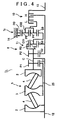
- FIG. 4 shows an infinitely variable transmission of which a portion has been modified.
- the structures of the continuously variable speed change unit (variator) 5, the planetary gear mechanism 6 1 , and the counter gear mechanism 7 1 are similar to those of the previous embodiment, but the connective relationships of the planetary gear mechanism 6 1 and the counter gear mechanism 7 1 are different. That is, the carrier C01 of the Low mode simple planetary gear 11 is connected to the sun gear S0 of the counter planetary gear 14 and the carrier C02 of the counter planetary gear 14 is connected to the output shaft 13 via the Low clutch L.
- the velocity diagram is the same as the velocity diagram shown in FIG. 2 . That is, in the Low mode, the rotation of the output carrier C01 is input to the sun gear S0 of the counter gear mechanism 7 2 . That rotation is then reversed because the ring gear R0 is fixed, and output from the carrier C02 to the output shaft 13.
- a Low brake that can hold the ring gear R0 stationary may of course also be used instead of the Low clutch.
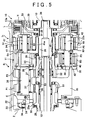
- FIG. 5 is a sectional view illustrating an example embodiment of the planetary gear mechanism 6 1 and the counter gear mechanism 7 1 according to the present invention.
- the planetary gear mechanism 6 1 has a front carrier C and a carrier C0 that is also used by the counter gear mechanism 7 1 .
- the front carrier C includes a carrier main body 33 and a carrier cover 35 which is integrally connected to the carrier main body.
- the carrier main body 33 is rotatably supported via a bearing 24 by an L-shaped plate 23 integrally attached to the transmission case 22.
- the carrier main body 33 is also connected to one of the input discs 2 of the variator 5, as well as spline-connected to the input shaft 12, which extends through the center of the variator 5, and tightened with a nut 35.
- the L-shaped plate 23 is integrally formed with a block that houses an actuator that operates the power roller 4 of the variator 5.
- the variator 5 and the planetary gear mechanism 6 1 are assembled as a sub-assembly to the L-shaped plate via the ball-bearing 24. This sub-assembly is then assembled to the case 22.
- a one-way clutch 34 is mounted adjacent to the ball-bearing 24 on the L-shaped plate 23. This one-way clutch 34 prevents reverse rotation of the input disc 2.
- a pinion shaft 36 is supported across the carrier main body 33 and the carrier cover 35.
- This pinion shaft 36 supports a first pinion P1 and a second pinion P2 arranged in the axial direction.
- the first pinion P 1 and the second pinion P2 are integrally formed and may have the same number of teeth, but in this example embodiment the number of teeth differs slightly.
- These common pinions P1, P2 are rotatably supported on the pinion shaft 36 via needle bearings 37, 37 (or bushes).
- the first pinion P1 is in mesh with the first sun gear S 1 and the second pinion P2 is in mesh with the second sun gear S2.
- the first sun gear S 1 is formed on an end portion of the hollow shaft 25.
- This hollow shaft 25 is rotatably supported around the input shaft 12 via a needle bearing 28.
- the hollow shaft 25 is also connected at the base end portion to the output disc 3 of the variator 5.
- the second sun gear S2 is formed on the base end portion of the intermediate shaft 26.
- the intermediate shaft 26 is rotatably supported at its base end portion via a needle bearing 29 around the (carrier C which is integrated with the) input shaft 12, and is connected at its tip end (i.e., the rearward) side to a clutch hub 30 of the High clutch H of the Low/High switching mechanism 10.
- a third sun gear S3 is connected to the intermediate shaft 26 by spline engagement and is prevented from slipping off by a snap ring 39.
- a ring gear R3 is integrally engaged with the carrier cover 35 of the front carrier C by a snap ring 40.
- the third sun gear S3, the ring gear R3, and the rear carrier C0 which is integral with the counter gear mechanism 7 1 together form the simple planetary gear 11 of the planetary gear mechanism 6 1 .
- the output (common) carrier C0 includes a carrier main body 41 that has a boss portion 41 a positioned in the center and on the inner radial side of the carrier C0, and front and rear carrier covers 42, 43 that form left and right side plates.
- the boss portion 41 a of the carrier main body 41 is rotatably supported via a bush 45 by the intermediate shaft 26.
- a pinion shaft 46 is non-rotatably supported between the carrier main body 41 and the carrier cover 42.
- a pinion P3 is rotatably supported on this pinion shaft 46. This pinion P3 is in mesh with the third sun gear S3 and the ring gear R3, and together these form the simple planetary gear 11.
- a first pinion shaft 47 and a second pinion shaft 49 are non-rotatably supported between the carrier main body 41 and the rear carrier cover 43.
- a fourth pinion P4 is rotatably supported on the first pinion shaft 47
- a fifth pinion P5 is rotatably supported on the second pinion shaft 49.
- These pinions P4, P5 are in mesh with each other, and one of the pinions P4 is also in mesh with the sun gear S0 while the other of the pinions P5 is in mesh with the ring gear R0. Together these form the double pinion planetary gear 14 of the counter gear mechanism 7. Further, the ring gear R0 is engaged with splines 22a that are formed on the transmission case 22 and is therefore a fixed ring gear.
- a Low clutch hub 50 is integrally formed with the sun gear S0 by welding or the like.
- the Low clutch L and High clutch H which are both wet type multiple disc clutches, are interposed between the hubs 30 and 50 and a drum 13a that is formed on the output shaft 13 (see FIG. 1 ). Together these form the Low/High switching mechanism 10.
- Thrust bearings 50, 51 are interposed between the end surface of the output shaft 13 positioned in the axial direction in the case 22 and the end surface of the sun gear S0 so as to sandwich the High clutch hub 30.
- a thrust bearing 52 is interposed between a step portion a of the intermediate shaft 26 and the carrier main body 41. These thrust bearings position the counter gear mechanism 7 1 and the Low/High switching mechanism 10 in the axial direction.
- a (first) thrust bearing 53 is interposed between the main body 33 of the carrier C which is positioned by the nut 35 on the input shaft 12, and the tip end (to the rear side of the vehicle) of the hollow shaft 25 which extends from the output disc and on which the first sun gear S1 is formed.
- a thrust bearing 55 is also interposed between a flange portion 25a of the hollow shaft 25 and the rear end of the input disc 2.
- a (second) thrust bearing 56 is interposed between the sun gear S3 and the rear end portion (i.e., the rear side surface of the carrier cover 35) of the front carrier C.
- the variator 5 and the planetary gear mechanism 6 1 are structures which are supported such that thrust is cancelled out, with the input shaft 12 and the front carrier C which is integral with the input shaft 12 in the axial direction, together with the output disc 3 and the hollow shaft 25 which is positioned in the axial direction by the thrust bearings 53, 55, 56 being a single unit.
- the pinion and sun gear (S 1 / P1) (S2 / P2) which are in mesh with each other in the planetary gear mechanism 6 1 are helical gears, so thrust forces from these act in directions such that they cancel each other out when power is being transmitted.
- the thrust generated in the first sun gear S 1 acts in the direction toward the right in the drawing (i.e., toward the rear of the vehicle) on the carrier C via the thrust bearing 53
- the thrust from the second sun gear S2 acts in the direction toward the left in the drawing (i.e., toward the front of the vehicle) on the third sun gear S3 via the intermediate shaft 26 and the snap ring 39
- the thrust forces of the first and second sun gears S1, S2 act to push against each other and therefore cancel each other out in the carrier C.
- the thrust of the second sun gear S2 acts on the carrier C via the thrust bearing 56 and the snap ring 39 that positions the third sun gear S3, a thrust bearing does not need to be provided between the second sun gear S2 and the carrier main body 33 so as to oppose the thrust bearing 53.
- the number of thrust bearings can be reduced and the continuously variable transmission can be made compact in the axial direction. Therefore, the two input discs 2, 2 are supported such that the large thrust forces (squeezing force) therebetween that are generated in the variator 5 cancel each other out, so the variator 5 and the planetary gear mechanism 6 1 are structures that are supported as a single system which cancels out the generated thrust.
- the pinion shaft 36 has a short structure (compared with the step pinion shown in FIG. 7 ) which is just long enough to support the two pinions P1, P2.
- the Low mode output gear is the simple planetary gear 11, so there is little restriction to the gear ratio for achieving the function as an IVT 1 2 and the pinion shaft 36 can have a large diameter.
- the bearing 37 can have a large diameter which increases its life span and the pinion shaft 36 has improved rigidity which reduces load fluctuations on the bearing due to bending of the shaft.
- the weight of the pinions is reduced which reduces the load caused by centrifugal load. As a result of these factors, the precision with which the pinions P1, P2 are supported can be maintained over an extended period of time.
- the variator 5 and the planetary gear mechanism 6 1 are supported as an integrated system such that the thrust forces acting on the first and second sun gears S1, S2 that are in mesh with the first and second pinions P1, P2 are cancelled out within the planetary gear mechanism 6 1 .
- the thrust load on the case 22 of the infinitely variable transmission 1 2 is also reduced.
- the counter gear mechanism 7 1 and the simple planetary gear 11 of the planetary gear mechanism 6 1 use the same carrier C0.
- the planetary gear mechanism 6 1 and the counter gear mechanism are connected in an organized manner.
- the precision of the infinitely variable transmission (IVT) is able to be improved, and the length of life is thus extended.
- the infinitely variable transmission (IVT) can be made more compact.
- a full toroidal-type continuously variable speed change unit is used.
- a half toroidal-type continuously variable speed change unit may of course also be used.
- the simple planetary gear 11 has a short, logical connective configuration, with the ring gear R3 connected to the front carrier C and the sun gear S3 connected to the second sun gear S2, but it is not limited to this configuration; other connective configurations are also possible.
- Rotation of an input shaft 12 is directly transmitted to a front carrier C of a planetary gear mechanism 6 1 , and rotation which is speed-changed and reversed by a variator 5 is transmitted to a sun gear S1.
Landscapes
- Engineering & Computer Science (AREA)
- General Engineering & Computer Science (AREA)
- Mechanical Engineering (AREA)
- Transmission Devices (AREA)
- Friction Gearing (AREA)
- Structure Of Transmissions (AREA)
Description
- The present invention relates to a continuously variable transmission which is able to obtain a wide range of output speed ratios compared with the speed ratios of a continuously variable speed-change unit, by combining a toroidal-type continuously variable speed change unit and a planetary gear mechanism and using torque circulation. More specifically, the present invention relates to a continuously variable transmission in which an input shaft and an output shaft are arranged on the same axis.
- A continuously variable transmission has been proposed which uses a toroidal-type continuously variable speed change unit and in which all of the members are arranged on a single axis (see WO Publication
WO03/100295A1 FIG. 6(a) , this continuouslyvariable transmission 1 includes a toroidal-type continuously variablespeed change unit 5, aplanetary gear mechanism 6, acounter gear mechanism 7, and a Low/High switching mechanism 10, all of which are arranged on a single axis between aninput shaft 12 and anoutput shaft 13. The toroidal-type continuously variablespeed change unit 5 includesinput discs 2 and anoutput disc 3, as well asrollers 4 arranged between these discs such that the radial position of contact with the discs can be changed. Theplanetary gear mechanism 6 has a carrier C1 on which three pinions P1, P2, P3 are arranged in the axial direction. Thecounter gear mechanism 7 has a carrier C2 on which two pinions P4, P5 are arranged in the axial direction. The Low/High switching mechanism 10 includes a Low brake L that can hold an output side sun gear S4 of the counter gear mechanism against rotation, and a High clutch H interposed between a second sun gear (i.e., a High mode output gear) S2 of the planetary gear and theoutput shaft 13. - Accordingly, when the continuously
variable transmission 1 is in a Low mode in which the Low brake L is applied and the High clutch H is released, rotation of the carrier C1 into which rotation is directly input from theinput shaft 12 combines, at theplanetary gear mechanism 6, with the rotation of an input side sun gear S1, the direction of which has been reversed and the speed of which has been changed, via the continuously variablespeed change unit 5. This combined rotation is then output to a Low mode output gear (i.e., a third sun gear) S3. The rotation of the output gear S3 is then reversed and output to theoutput shaft 13. - The Low/
High switching mechanism 10 may alternatively include a Low clutch L interposed between the carrier C2 and theoutput shaft 13, as shown inFIG. 6(b) , and a High clutch H interposed between the second sun gear S2 of the planetary gear and theoutput shaft 13 like that described above. - In this continuously variable transmission, the three pinions P1, P2, P3 of the
planetary gear mechanism 6 are aligned in series in the axial direction. In addition, the two pinions P4, P5 of thecounter gear mechanism 7 are also aligned in series in the axial direction. As a result, the continuously variable transmission is long in the axial direction. - In view of this, the inventors of the present application devised a continuously variable transmission in which the length in the axial direction is decreased by using a double pinion planetary gear for the counter gear mechanism. As shown in
FIG. 7 , this continuouslyvariable transmission 11 includes a toroidal-type continuously variablespeed change unit 5 and aplanetary gear mechanism 6, which are similar to those described above, and acounter gear mechanism 71 which is a double pinion planetary gear. That is, a carrier C0 rotatably supports pinions P4, P5 which are in mesh with each other, while one pinion P4 is in mesh with a sun gear S0 and the other pinion P5 is in mesh with a ring gear R0. The sun gear S0 is connected to the third sun gear (i.e., the Low mode output gear) S3 of theplanetary gear mechanism 6, the ring gear R0 is fixed to a case 15, and the carrier C0 is coupled to theoutput shaft 13 via the Low clutch L. - This continuously
variable transmission 11 operates as illustrated in the velocity diagram ofFIG. 8 . That is, in a Low mode in which the Low clutch L is applied and the High clutch H is released, rotation of the input shaft 12 (e.g., engine output rotation) is transmitted to the carrier C1 of theplanetary gear mechanism 6 via ahollow shaft 12a as well as reversed and transmitted to a first sun gear (i.e., an input gear) S1 via a toroidal-type continuously variable speed change unit (variator) 5. The rotation input to thecarrier C 1 and the reversed speed-changed rotation of theinput gear S 1 are combined while torque is circulated at theplanetary gear mechanism 6, and then output from the third sun gear (i.e., the Low mode side output gear) S3. - Here, because of the relationship between the input side gear ratio (
S 1 / P1) and the output side gear ratio (S3 / P3), when the continuously variable speed change unit (variator) 5 is at maximum overdrive (OD: the speed increase side), the output gear S3 rotates in the reverse direction (with the direction of rotation of theinput shaft 12 being the forward direction). When thevariator 5 shifts from OD to underdrive (UD: the speed decrease side), the output gear S3 passes through the zero rotation (GN: gear neutral) point and starts to rotate in the forward direction. When thevariator 5 is at maximum underdrive, maximum forward rotation is obtained. - The rotation of the output gear S3 is transmitted to the input sun gear S0 of the
counter gear mechanism 71, which is integrated with the output gear S3. That rotation is then reversed because the ring gear R0 is stationary, and output from the carrier C0. The rotation of the carrier C0 is then transmitted to theoutput shaft 13 via the Low clutch L which is applied. Therefore, the reverse rotation of the output gear S3 becomes forward rotation at the carrier C0 and theoutput shaft 13. When the continuouslyvariable transmission 11 is used as a transmission in an automobile, however, another counter mechanism, not shown, is provided in a differential mechanism on the downstream side in the transmission path of the continuouslyvariable transmission 11 so the forward rotation of theoutput shaft 13 actually becomes reverse rotation output for the vehicle. That is, when thevariator 5 changes from OD to UD, the output shaft (i.e., the carrier C0) 13 passes through the GN point (i.e., zero rotation) and shifts to forward rotation. - The mode switches from Low mode to High mode when the Low clutch L is released and the High clutch H is applied. In this state, rotation of the second sun gear (i.e., the High mode output gear) S2 of the
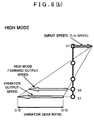
planetary gear mechanism 6 is output directly from theoutput shaft 13 via the High clutch H. As shown inFIG. 8(b) , rotation of theinput shaft 12 is directly transmitted to the carrier C1 of theplanetary gear mechanism 6, as well as reversed and transmitted to the first sun gear (i.e., the input gear) S1 via the toroidal-type continuously variable speed change unit (variator) 5. - The forward rotation of the carrier C1 is combined with the reversed speed-changed rotation of the first
sun gear S 1 at theplanetary gear mechanism 6, and that combined rotation is output from the second sun gear S2. Here, the input side gear ratio (S 1 / P1) and the output side gear ratio (S2 / P2) are values that are close or the same so an output speed is obtained in which the speed ratio (i.e., the gear ratio) of thevariator 5 is off in the reverse direction by a value that substantially corresponds to the forward output speed at maximum UD of thevariator 5 in the Low mode. That is, when thevariator 5 is at maximum UD, the second sun gear (i.e., the output gear) S2 is at the lowest forward output speed in the High mode. As thevariator 5 shifts from the UD side to the OD side, that forward output speed increases. Incidentally, the reverse rotation here actually results in forward rotation with respect to the output of the vehicle because of the other counter mechanism. - Accordingly, when the continuously
variable transmission 11 is in the Low mode and thevariator 5 is at maximum OD, maximum reverse speed is obtained. As thevariator 5 shifts to the UD side, it passes through the gear neutral (GN) point, after which forward rotation is obtained and the speed increases in the forward direction until the maximum forward output speed in the Low mode is reached when thevariator 5 is at the maximum UD position. When the continuouslyvariable transmission 11 is switched to the High mode in this state and thevariator 5 is at the maximum UD position, the lowest forward output speed in the High mode is obtained. The lowest output speed in the High mode is substantially the same as the highest output speed in the Low mode. In the High mode, the forward output speed also increases as thevariator 5 shifts in the OD direction, such that maximum forward output speed is achieved when thevariator 5 is at the maximum OD position. - Accordingly, in the continuously
variable transmission 11, when thevariator 5 shifts from the OD side to the UD side, rotation shifts from reverse rotation to forward rotation after passing through gear neutral. Then when the variator shifts from the maximum UD position toward OD, rotation continues in the forward direction and continues to increase until the maximum output speed is reached. - The continuously
variable transmission 11 shown inFIG. 7 described above is reduced in length in the axial direction by using a double pinion planetary gear in the counter gear mechanism. Theplanetary gear mechanism 6 for combining torque is configured such that three pinions are aligned in the axial direction (i.e., a three-step pinion), just like the continuouslyvariable transmission 1 disclosed inPatent Document 1 described above (seeFIG. 6 ). - As shown in
FIG. 9 , theplanetary gear mechanism 6 has the carrier C1 which serially supports, in the axial direction, the three pinions P1, P2, P3, a first sun gear (i.e., the input gear) S1 which is in mesh with the first pinion P1, a second sun gear (i.e., the High mode output gear) S2 which is in mesh with the second pinion P2, and a third sun gear (i.e., the Low mode output gear) S3 which is in mesh with the third pinion P3. The carrier C1 has a carriermain body 21 a, which is formed integrally with one of thediscs 2 of the toroidal-type continuously variable speed change unit (i.e., the variator 5), and acarrier cover 21b which is integrally formed with the carriermain body 21a. The carriermain body 21a is rotatably supported by atransmission case 22 via abearing 24. Also, apinion shaft 23 is provided on the carriermain body 21a and thecover 21b. The first, second, and third pinions P1, P2, P3, which are integrally formed, are rotatably supported via either a needle bearing 29 or a bush on theshaft 23. Here, a bush is also included in the concept of a bearing. - The first sun gear S1 is formed at an end portion of a
hollow shaft 25, the base portion of which is coupled to thecentral output disc 3 of the variator 5 (seeFIGS. 6 and7 ). An input shaft (core shaft) 12 is rotatably supported via a needle bearing or the like in the hollow portion of thehollow shaft 25. The base portion (toward the front of the vehicle) of thisinput shaft 12 is coupled to an engine output shaft via a damper, while the end portion (toward the rear of the vehicle) of theinput shaft 12 is spline-engaged to the carriermain body 21a. The second sun gear S2 is formed on anintermediate shaft 26 which is connected to the High clutch H of the Low/High switching mechanism (seeFIGS. 6 and7 ). The third sun gear S3 is formed on asleeve 27 which is rotatably fitted around theintermediate shaft 26. Thissleeve 27 is connected to the sun gear S0 of the counter gear mechanism 7 (seeFIGS. 6 and7 ). - The fact that the
pinion shaft 23 supports all three pinions P1, P2, P3 which are integrally formed serially in the axial direction makes thepinion shaft 23 long in the axial direction, and as described above, because it makes up an IVT (infinitely variable transmission) with torque circulation, i.e., because it performs continuously shifting with the highest forward output speed in the Low mode approximately matching the lowest forward output speed in High mode when thevariator 5 is at maximum UD, the gear diameter of the third pinion P3 is smaller, which means the diameter of thepinion shaft 23 also has to be smaller. - As a result, the diameter of the
bearing 29 is also smaller, which means the bearing will have a shorter life span. Further, the reduced diameter of the pinion shaft renders the pinion shaft insufficiently rigid, making it susceptible to bending which would increase the load on the bearing. The combination of these factors may result in insufficient precision and life span of the carrier C1. - Moreover, the three pinions P1, P2, P3 which are formed integral with one another are heavy, which results in a large centrifugal load acting on the carrier C1. The structure of the
planetary gear mechanism 6 is disadvantageous also with respect to loads such as this centrifugal load. - Also, because the three pinions P1, P2, P3 are aligned in series in the axial direction, the
planetary gear mechanism 6 is long in the axial direction such that even if the counter gear mechanism were shortened, the transmission would still be long in the axial direction for a continuously variable transmission. - The configuration of the continuously variable transmission shown in
FIGS. 7 and9 was undisclosed at the time of application of the present invention. - Furthermore, a continuously variable transmission according to the preamble of
claim 1 is known fromDE 100 21 912 A1 . - In view of the foregoing problem, it is the object of the present invention to provide a continuously variable transmission which is able to solve the foregoing problems using a simple planetary gear for a Low mode.
- According to the present invention, this object is solved with a continuously variable transmission having the features of
claim 1. - In detail the present invention provides a continuously variable transmission which includes the planetary gear mechanism includes a two-step pinion and a simple planetary gear. The pinion shaft is short but long enough to support two rows of pinions in the axial direction. As a result, the bearing which rotatably supports the two rows of pinions can be large in diameter, which increases the length of the bearing life span and reduces bending of the pinion shaft and thus the load fluctuation on the bearing that results from that bending. Further, the pinion weight is lightened such that the load caused by the centrifugal load is reduced. The combination of these factors improves the precision with which the pinion is supported and enables that high precision to be maintained over an extended period of time.
- Moreover, in the Low mode, power can be transmitted through the simple planetary gear, which makes it easier to set the gear ratio as an IVT. Also, increasing the number of teeth on the pinion of the first carrier makes it possible to maintain the gear strength at a small tooth width and shorten the planetary gear mechanism in the axial direction so that the continuously variable transmission can be made more compact.
- Further, the input shaft and the input disc of the toroidal speed change unit may be connected to the first carrier, the output disc of the toroidal speed change unit may be connected to the first sun gear, and the center portion of the toroidal speed change unit may be configured by two heavy shafts, thus resulting in compact and logical connective relationships.
- Additionally, the present invention further provides a continuously variable transmission which includes the planetary gear mechanism such that the first carrier is connected to the ring gear of the simple planetary gear and the second sun gear is connected to the sun gear of the simple planetary gear. As a result, the connections are succinct and logical so the length of the planetary gear mechanism is shorter in the axial direction, thereby enabling the continuously variable transmission to be made more compact as well as enabling the reliability of the continuously variable transmission to be increased.
- In addition, according to the foregoing structure, the counter gear mechanism may include a double pinion planetary gear. As a result, the counter gear mechanism can be made shorter in the axial direction, thus making the continuously variable transmission even more compact, enabling it to be shorter in the axial direction in particular.
- In addition, according to the foregoing structure, the carrier of the single planetary gear of the planetary gear mechanism may be formed integral with the carrier of the counter gear mechanism. As a result, the planetary gear mechanism and the counter gear mechanism are inseparably connected together so as to form an overall compact and simple mechanism, thus enabling the continuously variable transmission to be more compact and reliable.
- In addition, according to the foregoing structure, the toroidal-type continuously variable speed change unit, which receives a large force (thrust) in the axial direction, including the input shaft which is substantially integral with the input disc of the toroidal-type continuously variable speed change unit and the carrier of the planetary gear mechanism, may be supported such that thrust is cancelled out. Further, the continuously variable speed change unit and the first and second sun gears may be supported such that thrust, including the thrust that acts on the first and second sun gears, is cancelled out. As a result, the toroidal-type continuously variable speed change unit and the planetary gear mechanism are supported as a single system such that thrust is cancelled out, which enables highly precise support to be maintained over an extended period of time, thus increasing the length of life of the continuously variable transmission.
- In addition, according to the foregoing structure, the thrust generated in the planetary gear mechanism caused by the helical gears acts to cancel itself out in the planetary gear mechanism by the first thrust bearing interposed between the first sun gear and the first carrier and the second thrust bearing interposed between the first carrier and the sun gear of the simple planetary gear. Therefore, for example, it is no longer necessary to provide a thrust bearing between the first carrier and the second sun gear so the number of thrust bearings can be reduced, and the continuously variable transmission can be made more compact in the axial direction.
-
-
FIG. 1 is a schematic illustrating a configuration of an infinitely variable transmission according to the present invention; -
FIG. 2 is a velocity diagram, with (a) illustrating a Low mode and (b) illustrating a High mode; -
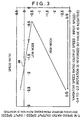
FIG. 3 is a graph showing the relationship between the speed ratio of a continuously variable speed change unit and the speed ratio of the continuously variable transmission; -
FIG. 4 is a schematic illustrating one embodiment of which a portion has been modified; -
FIG. 5 is a sectional view of a main portion of an embodiment according to the present invention; -
FIG. 6 is a schematic of related art, with (a) and (b) showing types having a portion that is different; -
FIG. 7 is a schematic showing prior technology of the present invention that was devised by the inventors which is based on the related art; -
FIG. 8 is a velocity diagram, with (a) illustrating a Low mode and (b) illustrating a High mode; and -
FIG. 9 is a sectional view showing a configuration of a main portion of the prior art. - Hereinafter, an example embodiment of the present invention will be described with reference to
FIGS. 1 to 5 . - An infinitely variable transmission (IVT) 12 includes a continuously variable speed change unit (variator) 5, a
planetary gear mechanism 61, acounter gear mechanism 71, and a Low/High switching mechanism 10, as shown inFIG. 1 . The continuously variablespeed change unit 5 is a full toroidal-type continuously variable speed change unit and includes twoinput discs input shaft 12, oneoutput disc 3 connected to ahollow shaft 25, andpower rollers input discs 2 and theoutput disc 3 have arc-shapedconcave grooves power rollers input discs 2 and theoutput disc 3. Thisvariator 5 has a speed ratio (i.e., output speed / input speed) of -0.4 to -2.5. The speed ratio is negative (minus) because theoutput disc 3 rotates in the opposite direction from theinput discs 2. - The
planetary gear mechanism 61 includes a front carrier (i.e., a first carrier) C which has two pinions P1, P2, and a Low mode simpleplanetary gear 11. This Low mode simpleplanetary gear 11 includes a rear carrier C0 which is in common with a double pinionplanetary gear 14 of thecounter gear mechanism 71. The two pinions (i.e., the first pinion and the second pinion) P1, P2 are integrally formed and are rotatably supported on a common pinion shaft. The front carrier C which supports these pinions is connected to a ring gear R3 of the Low mode simpleplanetary gear 11. The front carrier C is connected to theinput shaft 12 as well as to one of theinput discs 2, so rotation of theinput shaft 12 is transmitted. - The
first pinion P 1 is in mesh with the firstsun gear S 1 that is connected to theoutput disc 3 of thevariator 5. This firstsun gear S 1 serves as an input gear into which speed-changed rotation from thevariator 5 is input. The second pinion P2 is in mesh with the second sun gear S2 which serves as a High mode output gear. The second pinion P2 is also integrally connected to a (third) sun gear S3 of the Low mode simpleplanetary gear 11. These second and third sun gears S2, S3 are both connected to theoutput shaft 13 via a High clutch H of the Low/High switching mechanism 10 and thus serve as High mode output gears. - The
counter gear mechanism 71 includes a double pinionplanetary gear 14 that has two pinions (a fourth pinion P4 and a fifth pinion P5) which are in mesh with each other. The carrier C0 of the double pinionplanetary gear 14 is also integrally formed with the carrier of the Low mode simpleplanetary gear 11, as described above. A (second) ring gear R0 is fixed to acase 22, and a (fourth) sun gear S0 is connected to theoutput shaft 13 via a Low clutch L. - This infinitely variable transmission (IVT) 12 operates as illustrated in the velocity diagram in
FIG. 2 . In the velocity diagram inFIG. 2 , the first and second pinions P1, P2 are common long pinions, the gear ratios S1 / P1 and S2 / P2 are changed, and the output speed and the variator output line do not overlap. However, the gear ratios (S 1 / P1) (S2 / P2) may be the same and the output speed and the variator output line may of course overlap. - In the Low mode in which the Low clutch L is applied and the High clutch H is released, as shown in
FIG. 2(a) , the rotation of theinput shaft 12 which is connected to the engine output shaft is transmitted directly to the front carrier C and the ring gear R3 of theplanetary gear mechanism 61, and reversed and speed-changed rotation is transmitted to the first sun gear (i.e., the input gear) S1 via thevariator 5. The rotation of the front carrier C and the ring gear R3 and the speed-changed rotation (i.e., the variator speed ratio) of the firstsun gear S 1 are combined while torque is circulated at theplanetary gear mechanism 61 and the resultant rotation is output to the output carrier C0 of the Low mode simple planetary gear. Here, when thevariator 5 shifts from the OD side to the UD side, the output carrier C0 changes from reverse rotation to the gear neutral position (GN point), i.e., a position in which the output speed becomes zero and torque is endlessly released. When thevariator 5 shifts farther to the OD side, rotation of the output carrier C0 accelerates in the forward direction (i.e., the same direction as that in which the input shaft rotates). - The rotation of the output carrier C0 is directly transmitted to the carrier of the
counter gear mechanism 71, which is a common carrier. This rotation is then reversed because the ring gear R0 is held stationary, and output from the sun gear S0. As a result, the rotation of the output carrier C0 is reversed. Reverse rotation of the output carrier C0 is output as a reverse output speed to the sun gear S0 and forward rotation of the output carrier C0 is output as a forward output speed to the sun gear S0. - The mode switches from Low mode to High mode when the Low clutch L is released and the High clutch H is applied. In this state, rotation of the
input shaft 12 is directly transmitted to the front carrier C of theplanetary gear mechanism 61, while reversed speed-changed rotation is transmitted to the first sun gear S1 from thevariator 5. These two rotations are then combined by theplanetary gear mechanism 61 and output from the second sun gear S2 which serves as the High mode output gear. At this time, the sun gear S0 and the carrier C0 of thecounter gear mechanism 71 rotate idly because the Low clutch L is released. Therefore the ring gear R3 of theplanetary gear mechanism 61 also rotates idly. Also, the gear ratios S1 / P1 and S2 / P2 have close or the same values, so a rotation that is close to or the same as the speed-changed output rotation from the variator 5 (i.e., the variator gear ratio) is output from the second sun gear S2, and the variator gear ratio is output as a High mode forward output speed from theoutput shaft 13 because the High clutch H is applied. - The foregoing will now be explained with the graph in
FIG. 3 . That is, when the speed ratio (i.e., output speed / input speed) of thevariator 5 is at the OD end, (approximately -2.5), the infinitely variable transmission (IVT) 12 rotates at a predetermined speed ratio (approximately 0.25) in the forward direction (i.e., the positive direction). When thevariator 5 shifts continuously to the UD side, the speed ratio of theIVT 12 continuously decreases until the speed ratio of theIVT 12 becomes 0, i.e., reaches the gear neutral (GN) point, at a speed ratio near -1.8 of thevariator 5. Then, when thevariator 5 shifts continuously toward UD, the speed ratio of theIVT 12 continuously accelerates in the reverse direction (i.e., the negative direction). When thevariator 5 reaches the UD end (approximately -0.4), the speed ratio of theIVT 12 is approximately -0.5. - In this state, the mode switches to the High mode. When the speed ratio of the
variator 5 is at the UD end in the High mode, the speed ratio of theIVT 12 is the same value (i.e., approximately -0.5) that it was in the Low mode. This time, when the speed ratio of the variator shifts continuously from the UD end toward OD, the speed ratio of theIVT 12 accelerates continuously in the reverse direction (i.e., the negative direction) from the Low mode. The acceleration in the reverse direction continues as thevariator 5 shifts farther toward OD. When the speed ratio of thevariator 5 reaches the OD end (approximately -2.5), the speed ratio of theIVT 12 is approximately -2.75 which is the maximum speed ratio. - In the graph, the direction of rotation of the input shaft 12 (i.e., the direction of engine rotation) is the forward direction, so the speed ratio is denoted with a plus sign. Accordingly, the
variator 5 rotates in reverse due to the toroidal system, so the speed ratio thereof is negative. Because this infinitely variable transmission (IVT) 12 is used in a vehicle where rotation is reversed again by a counter gear in a differential mechanism, the vehicle travels in reverse when the speed ratio of theIVT 12 is positive, and forward when the speed ratio is negative. Accordingly, when thevariator 5 shifts from the OD end toward UD in the Low mode, the vehicle changes from reverse travel to forward travel after passing through gear neutral (GN). The vehicle then gradually accelerates and the mode switches to the High mode at the UD end of thevariator 5. When thevariator 5 shifts from the UD end toward OD, the vehicle continuously accelerates in the forward direction. -
FIG. 4 shows an infinitely variable transmission of which a portion has been modified. In this infinitelyvariable transmission 13, the structures of the continuously variable speed change unit (variator) 5, theplanetary gear mechanism 61, and thecounter gear mechanism 71 are similar to those of the previous embodiment, but the connective relationships of theplanetary gear mechanism 61 and thecounter gear mechanism 71 are different. That is, the carrier C01 of the Low mode simpleplanetary gear 11 is connected to the sun gear S0 of the counterplanetary gear 14 and the carrier C02 of the counterplanetary gear 14 is connected to theoutput shaft 13 via the Low clutch L. - In this example embodiment, when the Low mode output carrier C0 is replaced with the sun gear S0 and the output element S0 is replaced with the carrier C02 in
FIG. 2 , the velocity diagram is the same as the velocity diagram shown inFIG. 2 . That is, in the Low mode, the rotation of the output carrier C01 is input to the sun gear S0 of thecounter gear mechanism 72. That rotation is then reversed because the ring gear R0 is fixed, and output from the carrier C02 to theoutput shaft 13. In thecounter gear mechanisms -
FIG. 5 is a sectional view illustrating an example embodiment of theplanetary gear mechanism 61 and thecounter gear mechanism 71 according to the present invention. Theplanetary gear mechanism 61 has a front carrier C and a carrier C0 that is also used by thecounter gear mechanism 71. The front carrier C includes a carriermain body 33 and acarrier cover 35 which is integrally connected to the carrier main body. The carriermain body 33 is rotatably supported via abearing 24 by an L-shapedplate 23 integrally attached to thetransmission case 22. The carriermain body 33 is also connected to one of theinput discs 2 of thevariator 5, as well as spline-connected to theinput shaft 12, which extends through the center of thevariator 5, and tightened with anut 35. - The L-shaped
plate 23 is integrally formed with a block that houses an actuator that operates thepower roller 4 of thevariator 5. Thevariator 5 and theplanetary gear mechanism 61 are assembled as a sub-assembly to the L-shaped plate via the ball-bearing 24. This sub-assembly is then assembled to thecase 22. A one-way clutch 34 is mounted adjacent to the ball-bearing 24 on the L-shapedplate 23. This one-way clutch 34 prevents reverse rotation of theinput disc 2. - A
pinion shaft 36 is supported across the carriermain body 33 and thecarrier cover 35. Thispinion shaft 36 supports a first pinion P1 and a second pinion P2 arranged in the axial direction. Thefirst pinion P 1 and the second pinion P2 are integrally formed and may have the same number of teeth, but in this example embodiment the number of teeth differs slightly. These common pinions P1, P2 are rotatably supported on thepinion shaft 36 vianeedle bearings 37, 37 (or bushes). The first pinion P1 is in mesh with the firstsun gear S 1 and the second pinion P2 is in mesh with the second sun gear S2. - The first
sun gear S 1 is formed on an end portion of thehollow shaft 25. Thishollow shaft 25 is rotatably supported around theinput shaft 12 via aneedle bearing 28. Thehollow shaft 25 is also connected at the base end portion to theoutput disc 3 of thevariator 5. The second sun gear S2 is formed on the base end portion of theintermediate shaft 26. Theintermediate shaft 26 is rotatably supported at its base end portion via aneedle bearing 29 around the (carrier C which is integrated with the)input shaft 12, and is connected at its tip end (i.e., the rearward) side to aclutch hub 30 of the High clutch H of the Low/High switching mechanism 10. A third sun gear S3 is connected to theintermediate shaft 26 by spline engagement and is prevented from slipping off by asnap ring 39. Also, a ring gear R3 is integrally engaged with thecarrier cover 35 of the front carrier C by asnap ring 40. The third sun gear S3, the ring gear R3, and the rear carrier C0 which is integral with thecounter gear mechanism 71 together form the simpleplanetary gear 11 of theplanetary gear mechanism 61. - The output (common) carrier C0 includes a carrier
main body 41 that has aboss portion 41 a positioned in the center and on the inner radial side of the carrier C0, and front and rear carrier covers 42, 43 that form left and right side plates. Theboss portion 41 a of the carriermain body 41 is rotatably supported via abush 45 by theintermediate shaft 26. Apinion shaft 46 is non-rotatably supported between the carriermain body 41 and thecarrier cover 42. A pinion P3 is rotatably supported on thispinion shaft 46. This pinion P3 is in mesh with the third sun gear S3 and the ring gear R3, and together these form the simpleplanetary gear 11. - A
first pinion shaft 47 and asecond pinion shaft 49 are non-rotatably supported between the carriermain body 41 and therear carrier cover 43. A fourth pinion P4 is rotatably supported on thefirst pinion shaft 47, and a fifth pinion P5 is rotatably supported on thesecond pinion shaft 49. These pinions P4, P5 are in mesh with each other, and one of the pinions P4 is also in mesh with the sun gear S0 while the other of the pinions P5 is in mesh with the ring gear R0. Together these form the double pinionplanetary gear 14 of thecounter gear mechanism 7. Further, the ring gear R0 is engaged withsplines 22a that are formed on thetransmission case 22 and is therefore a fixed ring gear. A Lowclutch hub 50 is integrally formed with the sun gear S0 by welding or the like. The Low clutch L and High clutch H, which are both wet type multiple disc clutches, are interposed between thehubs drum 13a that is formed on the output shaft 13 (seeFIG. 1 ). Together these form the Low/High switching mechanism 10. -
Thrust bearings output shaft 13 positioned in the axial direction in thecase 22 and the end surface of the sun gear S0 so as to sandwich the Highclutch hub 30. Also, athrust bearing 52 is interposed between a step portion a of theintermediate shaft 26 and the carriermain body 41. These thrust bearings position thecounter gear mechanism 71 and the Low/High switching mechanism 10 in the axial direction. Further, a (first)thrust bearing 53 is interposed between themain body 33 of the carrier C which is positioned by thenut 35 on theinput shaft 12, and the tip end (to the rear side of the vehicle) of thehollow shaft 25 which extends from the output disc and on which the first sun gear S1 is formed. Athrust bearing 55 is also interposed between aflange portion 25a of thehollow shaft 25 and the rear end of theinput disc 2. In addition, a (second)thrust bearing 56 is interposed between the sun gear S3 and the rear end portion (i.e., the rear side surface of the carrier cover 35) of the front carrier C. - The
variator 5 and theplanetary gear mechanism 61 are structures which are supported such that thrust is cancelled out, with theinput shaft 12 and the front carrier C which is integral with theinput shaft 12 in the axial direction, together with theoutput disc 3 and thehollow shaft 25 which is positioned in the axial direction by thethrust bearings S 1 / P1) (S2 / P2) which are in mesh with each other in theplanetary gear mechanism 61 are helical gears, so thrust forces from these act in directions such that they cancel each other out when power is being transmitted. That is, the thrust generated in the firstsun gear S 1 acts in the direction toward the right in the drawing (i.e., toward the rear of the vehicle) on the carrier C via thethrust bearing 53, while the thrust from the second sun gear S2 acts in the direction toward the left in the drawing (i.e., toward the front of the vehicle) on the third sun gear S3 via theintermediate shaft 26 and thesnap ring 39, and further, acts in the direction toward the left in the drawing (i.e., toward the front of the vehicle) on the carrier C via thethrust bearing 56. Accordingly, the thrust forces of the first and second sun gears S1, S2 act to push against each other and therefore cancel each other out in the carrier C. Also, because the thrust of the second sun gear S2 acts on the carrier C via thethrust bearing 56 and thesnap ring 39 that positions the third sun gear S3, a thrust bearing does not need to be provided between the second sun gear S2 and the carriermain body 33 so as to oppose thethrust bearing 53. Thus, the number of thrust bearings can be reduced and the continuously variable transmission can be made compact in the axial direction. Therefore, the twoinput discs variator 5 cancel each other out, so thevariator 5 and theplanetary gear mechanism 61 are structures that are supported as a single system which cancels out the generated thrust. - The
pinion shaft 36 has a short structure (compared with the step pinion shown inFIG. 7 ) which is just long enough to support the two pinions P1, P2. Further, the Low mode output gear is the simpleplanetary gear 11, so there is little restriction to the gear ratio for achieving the function as anIVT 12 and thepinion shaft 36 can have a large diameter. As a result, the bearing 37 can have a large diameter which increases its life span and thepinion shaft 36 has improved rigidity which reduces load fluctuations on the bearing due to bending of the shaft. In addition, the weight of the pinions is reduced which reduces the load caused by centrifugal load. As a result of these factors, the precision with which the pinions P1, P2 are supported can be maintained over an extended period of time. - Also, the
variator 5 and theplanetary gear mechanism 61 are supported as an integrated system such that the thrust forces acting on the first and second sun gears S1, S2 that are in mesh with the first and second pinions P1, P2 are cancelled out within theplanetary gear mechanism 61. As a result, in combination with the thrust being cancelled out by the integrated structure of thevariator input disc 2 of the carrier C and theinput shaft 12, the thrust load on thecase 22 of the infinitelyvariable transmission 12 is also reduced. - Further, the
counter gear mechanism 71 and the simpleplanetary gear 11 of theplanetary gear mechanism 61 use the same carrier C0. As a result, theplanetary gear mechanism 61 and the counter gear mechanism are connected in an organized manner. These two factors enable the infinitelyvariable transmission 12 to be made compact in both the axial and radial directions. - According to the foregoing configuration, the precision of the infinitely variable transmission (IVT) is able to be improved, and the length of life is thus extended. In addition, the infinitely variable transmission (IVT) can be made more compact.
- In the example embodiment described above, a full toroidal-type continuously variable speed change unit is used. Alternatively, however, a half toroidal-type continuously variable speed change unit may of course also be used. Also, in the
planetary gear mechanism 61, the simpleplanetary gear 11 has a short, logical connective configuration, with the ring gear R3 connected to the front carrier C and the sun gear S3 connected to the second sun gear S2, but it is not limited to this configuration; other connective configurations are also possible.
Rotation of aninput shaft 12 is directly transmitted to a front carrier C of aplanetary gear mechanism 61, and rotation which is speed-changed and reversed by avariator 5 is transmitted to a sun gear S1. When a Low clutch L is applied, rotation of an output carrier C0 of a simpleplanetary gear 11 is transitted to acounter gear mechanism 71 via a common carrier, and output from anoutput shaft 13. When a High clutch H is applied, rotation of a sun gear S2 is transmitted to theoutput shaft 13. Thus, a pinion shaft is long and has a small diameter and the life span of the bearing is not sufficient with a planetary gear mechanism that has a three-step pinion.
Claims (10)
- A continuously variable transmission which comprises a planetary gear mechanism (6), a counter gear mechanism (7), and a Low/High switching mechanism (10), wherein:the planetary gear mechanism (6) comprises a first carrier (C) that has a first pinion (P1) and a second pinion (P2) which are arranged in the axial direction and which rotate together as a unit, a first sun gear (S1) that is in mesh with the first pinion (P1),characterized in thatthe planetary gear mechanism (6) comprises one simple planetary gear (11) which transmits rotation of the first carrier (C) and of the first sun gear (S1) to the counter gear mechanism (7), wherein the simple planetary gear (11) has a first element (R3), a second element (S3), and a third element (C0), wherein the first carrier (C) is connected to the first element (R3) of the simple planetary gear (11) and the second sun gear (S2) is connected to the second element (S3) of the simple planetary gear (11).
- The continuously variable transmission according to claim 1, wherein the second sun gear (S2) is in mesh with the second pinion (P2).
- The continuously variable transmission according to claims 1 or 2, further comprising a toroidal-type continuously variable speed change unit (5), wherein
rotation of an input shaft is input to the first carrier (C), and output rotation, which is the rotation of the input shaft (12) after the direction and speed thereof have been changed by the toroidal-type continuously variable speed change unit (5), is input to the first sun gear (S1). - The continuously variable transmission according to any of claims 1 or 3, wherein
in a Low mode according to the Low/High switching mechanism (10), rotation of the third element (C0) of the simple planetary gear (11) is reversed in direction by the counter gear mechanism (7) and output to an output shaft (13); and
in a High mode according to the Low/High switching mechanism (10), rotation of the second sun gear (S2) is output to the output shaft (13). - The continuously variable transmission according to any of claims 1, 3 or 4, wherein the first element (R3) of the simple planetary gear (11) is a ring gear (R3), the second element (S3) is a sun gear (S3), and the third element is a carrier (C0, C01).
- The continuously variable transmission according to claim 5, wherein the third carrier (C0, C01) has a third pinion (P3) that is in mesh with the ring gear (R3) and the sun gear (S3) of the simple planetary gear (11).
- The continuously variable transmission according to claim 5 or 6, wherein the counter gear mechanism (7) includes a double pinion planetary gear (14) that has a third carrier (C0) which supports fourth and fifth pinions (P4, P5) that are in mesh with each other, a fourth sun gear (S0) that is in mesh with the fourth pinion (P4), and
a second ring gear (R0) that is in mesh with the fifth pinion (P5);
the carrier (C0) of the simple planetary gear (11) in the planetary gear mechanism (6) and the third carrier (C0) are integrally formed; and,
in the Low mode, rotation of the fourth sun gear (S0) is transmitted to the output shaft (13) while the second ring gear (R0) is held against rotation. - The continuously variable transmission according to claim 5 or 6, wherein the counter gear mechanism (7) includes a double pinion planetary gear that has a third carrier (C01) which supports fourth (P4) and fifth pinions (P5) that are in mesh with each other, a fourth sun gear (S0) that is in mesh with the third pinion (C01), and a second ring gear (R0) that is in mesh with the fifth pinion (P5);
the carrier (C01) of the simple planetary gear (11) in the planetary gear mechanism (6) and the fourth sun gear (S0) are connected; and,
in the Low mode, rotation of the third carrier (C01) is transmitted to the output shaft (13) while the second ring gear (R0) is held against rotation. - The continuously variable transmission according to any one of claims 1, 3 to 8, wherein the toroidal-type continuously variable speed change unit (5) has two input discs (2), an output disc (3) positioned between these two input discs (2), and rollers (4) sandwiched between the input discs (2) and the output disc (3);
the two input discs (2), the input shaft (12), and the first carrier (C) of the planetary gear mechanism (6) are all substantially formed integrally with one another and the continuously variable speed change unit (5) and the planetary gear mechanism (6) are supported such that thrust is cancelled out; and
the first and second sun gears (S1, S2) are supported in the thrust direction via thrust bearings (53) with respect to the integrally formed first carrier (C) or input shaft (12). - The continuously variable transmission according to claim 9, wherein the first thrust (53) bearing is interposed between the first sun gear (S1) and the first carrier (C);
a second thrust bearing (56) is interposed between the first carrier (C) and the sun gear (S3) of the simple planetary gear (11); and
thrust from the first sun gear (S1) that acts on the first carrier (C) and thrust from the second sun gear (S2) that acts via the third sun gear (56) which is integrated with the second sun gear (S2) in substantially the axial direction work to push against each other with substantially the same force via the first and second thrust bearings (53, 56).
Applications Claiming Priority (1)
| Application Number | Priority Date | Filing Date | Title |
|---|---|---|---|
| JP2005047823A JP4626337B2 (en) | 2005-02-23 | 2005-02-23 | Continuously variable transmission |
Publications (3)
| Publication Number | Publication Date |
|---|---|
| EP1696152A2 EP1696152A2 (en) | 2006-08-30 |
| EP1696152A3 EP1696152A3 (en) | 2009-12-23 |
| EP1696152B1 true EP1696152B1 (en) | 2011-08-24 |
Family
ID=36101529
Family Applications (1)
| Application Number | Title | Priority Date | Filing Date |
|---|---|---|---|
| EP06110299A Not-in-force EP1696152B1 (en) | 2005-02-23 | 2006-02-22 | Continously varialble transmission |
Country Status (3)
| Country | Link |
|---|---|
| US (1) | US7335126B2 (en) |
| EP (1) | EP1696152B1 (en) |
| JP (1) | JP4626337B2 (en) |
Families Citing this family (26)
| Publication number | Priority date | Publication date | Assignee | Title |
|---|---|---|---|---|
| JP4738298B2 (en) * | 2006-09-15 | 2011-08-03 | 株式会社エクォス・リサーチ | Continuously variable transmission |
| JP4867540B2 (en) * | 2006-09-20 | 2012-02-01 | 日本精工株式会社 | Continuously variable transmission |
| GB0703351D0 (en) * | 2007-02-21 | 2007-03-28 | Torotrak Dev Ltd | Continuously variable transmission |
| JP2009079699A (en) * | 2007-09-26 | 2009-04-16 | Nsk Ltd | Continuously variable transmission |
| US8257217B2 (en) * | 2009-02-03 | 2012-09-04 | Ford Global Technologies, Llc | Infinitely variable transmission with offset output shaft |
| US8417411B2 (en) * | 2009-04-22 | 2013-04-09 | GM Global Technology Operations LLC | Torque sensor performance diagnostic systems and methods |
| US9347532B2 (en) | 2012-01-19 | 2016-05-24 | Dana Limited | Tilting ball variator continuously variable transmission torque vectoring device |
| EP2815152A1 (en) | 2012-02-15 | 2014-12-24 | Dana Limited | Transmission and driveline having a tilting ball variator continuously variable transmission |
| CN104769325A (en) | 2012-09-06 | 2015-07-08 | 德纳有限公司 | Transmission having a continuously or infinitely variable variator drive |
| US9052000B2 (en) | 2012-09-07 | 2015-06-09 | Dana Limited | Ball type CVT/IVT including planetary gear sets |
| JP6247690B2 (en) | 2012-09-07 | 2017-12-13 | デーナ リミテッド | Ball CVT with output connection power path |
| CN104769329B (en) | 2012-09-07 | 2017-06-23 | 德纳有限公司 | Ball-type continous way buncher/unlimited formula buncher |
| US9353842B2 (en) | 2012-09-07 | 2016-05-31 | Dana Limited | Ball type CVT with powersplit paths |
| US9638296B2 (en) | 2012-09-07 | 2017-05-02 | Dana Limited | Ball type CVT including a direct drive mode |
| CN104755812A (en) | 2012-09-07 | 2015-07-01 | 德纳有限公司 | Ivt based on a ball type cvp including powersplit paths |
| US10030748B2 (en) | 2012-11-17 | 2018-07-24 | Dana Limited | Continuously variable transmission |
| WO2014117167A1 (en) | 2013-01-28 | 2014-07-31 | Robert Hornblower Meyer | Continuously variable drive mechanism |
| WO2014124063A1 (en) | 2013-02-08 | 2014-08-14 | Microsoft Corporation | Pervasive service providing device-specific updates |
| WO2014159755A2 (en) | 2013-03-14 | 2014-10-02 | Dana Limited | Ball type continuously variable transmission |
| EP2971860A4 (en) | 2013-03-14 | 2016-12-28 | Dana Ltd | Transmission with cvt and ivt variator drive |
| JP2016520782A (en) | 2013-06-06 | 2016-07-14 | デーナ リミテッド | 3 mode front wheel drive and rear wheel drive continuously variable planetary transmission |
| US10088022B2 (en) | 2013-11-18 | 2018-10-02 | Dana Limited | Torque peak detection and control mechanism for a CVP |
| WO2015073883A1 (en) | 2013-11-18 | 2015-05-21 | Dana Limited | Infinite variable transmission with planetary gear set |
| US10030594B2 (en) | 2015-09-18 | 2018-07-24 | Dana Limited | Abuse mode torque limiting control method for a ball-type continuously variable transmission |
| WO2017058862A1 (en) * | 2015-10-02 | 2017-04-06 | Dana Limited | Torque control methods for vehicles having a continuously variable planetary |
| KR102494648B1 (en) * | 2016-04-12 | 2023-01-31 | 알리손 트랜스미션, 인크. | continuously variable gearbox |
Family Cites Families (3)
| Publication number | Priority date | Publication date | Assignee | Title |
|---|---|---|---|---|
| US5607372A (en) * | 1995-01-13 | 1997-03-04 | The Torax Company, Inc. | Co-axial drive for a toroidal drive type transmission |
| DE10021912A1 (en) * | 2000-05-05 | 2001-11-08 | Daimler Chrysler Ag | Drive train for motor vehicle has second planet wheel with diameter such that for stepping up of variable speed gear contact point of second planet wheel with driven element corresponds to center of rotation of second planet wheel |
| JP4330528B2 (en) * | 2002-05-28 | 2009-09-16 | トロトラク・(ディヴェロプメント)・リミテッド | Continuously variable ratio transmission |
-
2005
- 2005-02-23 JP JP2005047823A patent/JP4626337B2/en not_active Expired - Fee Related
-
2006
- 2006-02-22 EP EP06110299A patent/EP1696152B1/en not_active Not-in-force
- 2006-02-22 US US11/358,056 patent/US7335126B2/en active Active
Also Published As
| Publication number | Publication date |
|---|---|
| JP2006234041A (en) | 2006-09-07 |
| JP4626337B2 (en) | 2011-02-09 |
| EP1696152A2 (en) | 2006-08-30 |
| US7335126B2 (en) | 2008-02-26 |
| US20060189432A1 (en) | 2006-08-24 |
| EP1696152A3 (en) | 2009-12-23 |
Similar Documents
| Publication | Publication Date | Title |
|---|---|---|
| EP1696152B1 (en) | Continously varialble transmission | |
| US8142323B2 (en) | Continuously variable transmission | |
| US9568083B2 (en) | Infinitely-variable transmission for a vehicle | |
| US20040166984A1 (en) | Continuously variable transmission apparatus | |
| US6517461B2 (en) | Infinitely variable transmission | |
| JP4867540B2 (en) | Continuously variable transmission | |
| US6520884B2 (en) | Torque-split type continuously variable transmission | |
| JP4281370B2 (en) | Continuously variable transmission | |
| JP4506541B2 (en) | Continuously variable transmission | |
| US6916266B2 (en) | Torque division angle drive gearbox | |
| JP4626371B2 (en) | Continuously variable transmission | |
| JPH08285033A (en) | Belt-type continuously variable transmission | |
| JP2004211852A (en) | Continuously variable transmission | |
| JP2007051695A (en) | Vehicle driving device | |
| JP4696770B2 (en) | Continuously variable transmission | |
| JP4715794B2 (en) | Continuously variable transmission | |
| US9625019B2 (en) | Infinitely variable transmission | |
| JP4715795B2 (en) | Continuously variable transmission | |
| JP4645615B2 (en) | Continuously variable transmission | |
| JP4144166B2 (en) | Continuously variable transmission for pumping pump or generator | |
| JP2006322482A (en) | Continuously variable transmission device | |
| JP4072530B2 (en) | Power split type continuously variable transmission | |
| JP4506540B2 (en) | Continuously variable transmission | |
| JP4631876B2 (en) | Toroidal continuously variable transmission | |
| JP2005331078A (en) | Continuously variable transmission |
Legal Events
| Date | Code | Title | Description |
|---|---|---|---|
| PUAI | Public reference made under article 153(3) epc to a published international application that has entered the european phase |
Free format text: ORIGINAL CODE: 0009012 |
|
| AK | Designated contracting states |
Kind code of ref document: A2 Designated state(s): AT BE BG CH CY CZ DE DK EE ES FI FR GB GR HU IE IS IT LI LT LU LV MC NL PL PT RO SE SI SK TR |
|
| AX | Request for extension of the european patent |
Extension state: AL BA HR MK YU |
|
| PUAL | Search report despatched |
Free format text: ORIGINAL CODE: 0009013 |
|
| AK | Designated contracting states |
Kind code of ref document: A3 Designated state(s): AT BE BG CH CY CZ DE DK EE ES FI FR GB GR HU IE IS IT LI LT LU LV MC NL PL PT RO SE SI SK TR |
|
| AX | Request for extension of the european patent |
Extension state: AL BA HR MK YU |
|
| 17P | Request for examination filed |
Effective date: 20100610 |
|
| AKX | Designation fees paid |
Designated state(s): DE FR GB |
|
| GRAP | Despatch of communication of intention to grant a patent |
Free format text: ORIGINAL CODE: EPIDOSNIGR1 |
|
| RAP1 | Party data changed (applicant data changed or rights of an application transferred) |
Owner name: KABUSHIKI KAISHA EQUOS RESEARCH |
|
| GRAS | Grant fee paid |
Free format text: ORIGINAL CODE: EPIDOSNIGR3 |
|
| GRAA | (expected) grant |
Free format text: ORIGINAL CODE: 0009210 |
|
| AK | Designated contracting states |
Kind code of ref document: B1 Designated state(s): DE FR GB |
|
| REG | Reference to a national code |
Ref country code: GB Ref legal event code: FG4D |
|
| REG | Reference to a national code |
Ref country code: DE Ref legal event code: R096 Ref document number: 602006023944 Country of ref document: DE Effective date: 20111027 |
|
| PLBE | No opposition filed within time limit |
Free format text: ORIGINAL CODE: 0009261 |
|
| STAA | Information on the status of an ep patent application or granted ep patent |
Free format text: STATUS: NO OPPOSITION FILED WITHIN TIME LIMIT |
|
| 26N | No opposition filed |
Effective date: 20120525 |
|
| REG | Reference to a national code |
Ref country code: DE Ref legal event code: R097 Ref document number: 602006023944 Country of ref document: DE Effective date: 20120525 |
|
| REG | Reference to a national code |
Ref country code: FR Ref legal event code: ST Effective date: 20121031 |
|
| PG25 | Lapsed in a contracting state [announced via postgrant information from national office to epo] |
Ref country code: FR Free format text: LAPSE BECAUSE OF NON-PAYMENT OF DUE FEES Effective date: 20120229 |
|
| PGFP | Annual fee paid to national office [announced via postgrant information from national office to epo] |
Ref country code: GB Payment date: 20210210 Year of fee payment: 16 Ref country code: DE Payment date: 20210209 Year of fee payment: 16 |
|
| REG | Reference to a national code |
Ref country code: DE Ref legal event code: R119 Ref document number: 602006023944 Country of ref document: DE |
|
| GBPC | Gb: european patent ceased through non-payment of renewal fee |
Effective date: 20220222 |
|
| PG25 | Lapsed in a contracting state [announced via postgrant information from national office to epo] |
Ref country code: GB Free format text: LAPSE BECAUSE OF NON-PAYMENT OF DUE FEES Effective date: 20220222 Ref country code: DE Free format text: LAPSE BECAUSE OF NON-PAYMENT OF DUE FEES Effective date: 20220901 |