EP1696139A2 - An assembly for the threaded connection of a threaded tubular rivet and a spacer bush - Google Patents
An assembly for the threaded connection of a threaded tubular rivet and a spacer bush Download PDFInfo
- Publication number
- EP1696139A2 EP1696139A2 EP06110233A EP06110233A EP1696139A2 EP 1696139 A2 EP1696139 A2 EP 1696139A2 EP 06110233 A EP06110233 A EP 06110233A EP 06110233 A EP06110233 A EP 06110233A EP 1696139 A2 EP1696139 A2 EP 1696139A2
- Authority
- EP
- European Patent Office
- Prior art keywords
- assembly
- threaded
- bush
- zone
- tubular rivet
- Prior art date
- Legal status (The legal status is an assumption and is not a legal conclusion. Google has not performed a legal analysis and makes no representation as to the accuracy of the status listed.)
- Granted
Links
- 125000006850 spacer group Chemical group 0.000 title claims abstract description 7
- 239000000463 material Substances 0.000 description 6
- 230000000295 complement effect Effects 0.000 description 4
- 239000000853 adhesive Substances 0.000 description 3
- 230000001070 adhesive effect Effects 0.000 description 3
- 239000011248 coating agent Substances 0.000 description 1
- 238000000576 coating method Methods 0.000 description 1
- 238000002347 injection Methods 0.000 description 1
- 239000007924 injection Substances 0.000 description 1
Images




Classifications
-
- F—MECHANICAL ENGINEERING; LIGHTING; HEATING; WEAPONS; BLASTING
- F16—ENGINEERING ELEMENTS AND UNITS; GENERAL MEASURES FOR PRODUCING AND MAINTAINING EFFECTIVE FUNCTIONING OF MACHINES OR INSTALLATIONS; THERMAL INSULATION IN GENERAL
- F16B—DEVICES FOR FASTENING OR SECURING CONSTRUCTIONAL ELEMENTS OR MACHINE PARTS TOGETHER, e.g. NAILS, BOLTS, CIRCLIPS, CLAMPS, CLIPS OR WEDGES; JOINTS OR JOINTING
- F16B37/00—Nuts or like thread-engaging members
- F16B37/04—Devices for fastening nuts to surfaces, e.g. sheets, plates
- F16B37/06—Devices for fastening nuts to surfaces, e.g. sheets, plates by means of welding or riveting
- F16B37/062—Devices for fastening nuts to surfaces, e.g. sheets, plates by means of welding or riveting by means of riveting
- F16B37/065—Devices for fastening nuts to surfaces, e.g. sheets, plates by means of welding or riveting by means of riveting by deforming the material of the nut
- F16B37/067—Devices for fastening nuts to surfaces, e.g. sheets, plates by means of welding or riveting by means of riveting by deforming the material of the nut the material of the nut being deformed by a threaded member generating axial movement of the threaded part of the nut, e.g. blind rivet type
-
- F—MECHANICAL ENGINEERING; LIGHTING; HEATING; WEAPONS; BLASTING
- F16—ENGINEERING ELEMENTS AND UNITS; GENERAL MEASURES FOR PRODUCING AND MAINTAINING EFFECTIVE FUNCTIONING OF MACHINES OR INSTALLATIONS; THERMAL INSULATION IN GENERAL
- F16B—DEVICES FOR FASTENING OR SECURING CONSTRUCTIONAL ELEMENTS OR MACHINE PARTS TOGETHER, e.g. NAILS, BOLTS, CIRCLIPS, CLAMPS, CLIPS OR WEDGES; JOINTS OR JOINTING
- F16B5/00—Joining sheets or plates, e.g. panels, to one another or to strips or bars parallel to them
- F16B5/01—Joining sheets or plates, e.g. panels, to one another or to strips or bars parallel to them by means of fastening elements specially adapted for honeycomb panels
Definitions
- the present invention relates to an assembly for the threaded connection of a threaded tubular rivet and a spacer bush, which assembly is suitable in particular for a material having a sandwich type structure, in which it is necessary to provide a threaded seat.
- the object of the present invention is to provide a device for fixing a threaded tubular rivet and a spacer bush, which allows a threaded seat to be provided in a sandwich type structure, which is simple to construct and easy to use and which at the same time allows a localized increase in the structural strength of the sandwich type structure.
- the present invention achieves the above-mentioned objects by means of an assembly for the threaded connection of a threaded tubular rivet and a spacer bush having the features referred to specifically in the appended claims.
- a threaded connection assembly in accordance with the invention is positioned in a receiving seat 4 of a material 6 having a sandwich type structure.
- a blind hole is formed in the material 6 in such a manner that the assembly 2 to which the present invention relates is positioned therein without coming into contact with the blind wall of the seat 4.
- the assembly 2 comprises a support head 10, a deformation chamber 12, a first externally threaded zone 14 and a second internally threaded zone 16, a support bush 18 which co-operates with the externally threaded zone 14, and the support bush 18 has a seat or recess 20 for receiving a tool for adjustment having a shape complementary to the recess 20.
- the deformation chamber 12 is deformed by means of a positioning tool A, thereby fixing the assembly 2 to the receiving seat 4 ( Figures 2-5).
- a tool having a shape complementary to the recess 20 is used to adjust the support bush 18 by rotation until it is brought into abutment against the blind wall of the seat 4.
- the material 6 having a sandwich type structure is greatly strengthened and - by means of the internal threading 16 - it is possible to fix an element E to the assembly 2 by means of a screw or other threaded assembly device.
- connection assembly according to the invention is generally designated 2.
- the assembly 2 is positioned in a receiving seat 4 of a material 6 having a sandwich type structure.
- the receiving seat 4 is formed by a hole 7 and a hole 7' having smaller dimensions than the hole 7, which holes are arranged in the same axis.
- the assembly 2 comprises a support head 10, a deformation chamber 12, a first externally threaded zone 14 and a second internally threaded zone 16, and a support bush 18 which co-operates with the externally threaded zone 14.
- the support bush 18 has a seat or recess 20 for receiving an adjustment tool having a shape complementary to the recess 20.
- the diameter of the support bush 18 is greater than the diameter of the hole 7', as will be clearly appreciated below.
- the deformation chamber 12 is deformed by means of a positioning tool A, thereby fixing the assembly 2 to the receiving seat 4 ( Figures 10-13).
- the support bush 18 is adjusted, by means of a tool having a shape complementary to the recess 20, via the hole 7', by rotation until it is brought into abutment against the wall in which the hole 7' is formed.
- an element E it is possible for an element E to be fixed to the sandwich type structure 6 at the assembly 2 by means of a screw or other threaded assembly device, thereby obtaining flush fixing between the element E and the structure 6.
- the assembly to which the present invention relates is advantageously used for the provision of threaded seats in materials having a sandwich type structure, increasing the structural strength thereof; the mechanical fixing of the assembly does not require waiting times during use owing to the need for setting of any adhesives.
- the external part of the assembly may be entirely or partially knurled; through-holes for optional injection of adhesive after positioning may be formed in the support head, which may be of any geometric shape, and the external walls of the assembly 2 may be provided for total or partial deposit of an adhesive coating.
Landscapes
- Engineering & Computer Science (AREA)
- General Engineering & Computer Science (AREA)
- Mechanical Engineering (AREA)
- Mutual Connection Of Rods And Tubes (AREA)
- Connection Of Plates (AREA)
- Dowels (AREA)
- Joining Of Building Structures In Genera (AREA)
Abstract
Description
- The present invention relates to an assembly for the threaded connection of a threaded tubular rivet and a spacer bush, which assembly is suitable in particular for a material having a sandwich type structure, in which it is necessary to provide a threaded seat.
- The object of the present invention is to provide a device for fixing a threaded tubular rivet and a spacer bush, which allows a threaded seat to be provided in a sandwich type structure, which is simple to construct and easy to use and which at the same time allows a localized increase in the structural strength of the sandwich type structure.
- The present invention achieves the above-mentioned objects by means of an assembly for the threaded connection of a threaded tubular rivet and a spacer bush having the features referred to specifically in the appended claims.
- Further features and advantages of the present invention will become clear from the following detailed description, given purely by way of non-limiting example with reference to the appended drawings, in which:
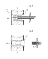
- Figures 1-8 illustrate the succession of steps for assembling a threaded connection assembly in accordance with the invention in a first embodiment thereof; and
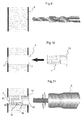
- Figures 9-16 illustrate the succession of steps for assembling a threaded connection assembly in accordance with the invention in a second embodiment thereof.
- With reference to Figures 1-8, a threaded connection assembly in accordance with the invention, generally designated 2, is positioned in a receiving
seat 4 of amaterial 6 having a sandwich type structure. - A blind hole is formed in the
material 6 in such a manner that theassembly 2 to which the present invention relates is positioned therein without coming into contact with the blind wall of theseat 4. - The
assembly 2 comprises asupport head 10, adeformation chamber 12, a first externally threadedzone 14 and a second internally threadedzone 16, asupport bush 18 which co-operates with the externally threadedzone 14, and thesupport bush 18 has a seat or recess 20 for receiving a tool for adjustment having a shape complementary to therecess 20. - Once the
assembly 2 has been positioned in thereceiving seat 4, thedeformation chamber 12 is deformed by means of a positioning tool A, thereby fixing theassembly 2 to the receiving seat 4 (Figures 2-5). - Once this has been carried out, a tool having a shape complementary to the
recess 20 is used to adjust thesupport bush 18 by rotation until it is brought into abutment against the blind wall of theseat 4. - In this manner, the
material 6 having a sandwich type structure is greatly strengthened and - by means of the internal threading 16 - it is possible to fix an element E to theassembly 2 by means of a screw or other threaded assembly device. - With reference to Figures 9-16, which illustrate an assembly for the threaded connection of a threaded tubular rivet and a spacer bush according to the invention, in a second embodiment and in which elements identical or corresponding to those of Figures 1-8 are indicated with the same reference numerals, the connection assembly according to the invention is generally designated 2.
- The
assembly 2 is positioned in a receivingseat 4 of amaterial 6 having a sandwich type structure. - The
receiving seat 4 is formed by ahole 7 and a hole 7' having smaller dimensions than thehole 7, which holes are arranged in the same axis. - The
assembly 2 comprises asupport head 10, adeformation chamber 12, a first externally threadedzone 14 and a second internally threadedzone 16, and asupport bush 18 which co-operates with the externally threadedzone 14. - The
support bush 18 has a seat or recess 20 for receiving an adjustment tool having a shape complementary to therecess 20. - The diameter of the
support bush 18 is greater than the diameter of the hole 7', as will be clearly appreciated below. - Once the
assembly 2 has been positioned in thereceiving seat 4, thedeformation chamber 12 is deformed by means of a positioning tool A, thereby fixing theassembly 2 to the receiving seat 4 (Figures 10-13). - Once this is effected, the
support bush 18 is adjusted, by means of a tool having a shape complementary to therecess 20, via the hole 7', by rotation until it is brought into abutment against the wall in which the hole 7' is formed. - Referring to the second embodiment described above, it is possible for an element E to be fixed to the
sandwich type structure 6 at theassembly 2 by means of a screw or other threaded assembly device, thereby obtaining flush fixing between the element E and thestructure 6. - The above makes clear the advantages of the assembly to which the present invention relates.
- The assembly to which the present invention relates is advantageously used for the provision of threaded seats in materials having a sandwich type structure, increasing the structural strength thereof; the mechanical fixing of the assembly does not require waiting times during use owing to the need for setting of any adhesives.
- Naturally, the principle of the invention remaining the same, the description and illustrations may be varied widely, without thereby departing from the scope of protection of the present invention.
- For example, the external part of the assembly may be entirely or partially knurled; through-holes for optional injection of adhesive after positioning may be formed in the support head, which may be of any geometric shape, and the external walls of the
assembly 2 may be provided for total or partial deposit of an adhesive coating.
Claims (2)
- An assembly for the threaded connection of a threaded tubular rivet and a spacer bush, characterized in that it comprises a support head (10), a deformation chamber (12), a first externally threaded zone (14) and a second internally threaded zone (16), a support bush (18) which co-operates with the external threading of the first zone (14), and a recess (20) which is capable of allowing the adjustment of the support bush (18).
- A method for assembly in a sandwich type structure comprising, between a first and a second wall, the assembly according to claim 1, characterized in that it comprises the steps of:- positioning the assembly (2) in a receiving seat (4);- deforming the deformation chamber (12); and- rotating the support bush (18), bringing it into abutment against the second wall. All substantially as described and illustrated and for the purposes specified.
Applications Claiming Priority (1)
| Application Number | Priority Date | Filing Date | Title |
|---|---|---|---|
| IT000124A ITTO20050124A1 (en) | 2005-02-28 | 2005-02-28 | THREADED TUBULAR RIVET THREADED COUPLING COMPLEX AND DISTANCE BUSHING. |
Publications (4)
| Publication Number | Publication Date |
|---|---|
| EP1696139A2 true EP1696139A2 (en) | 2006-08-30 |
| EP1696139A8 EP1696139A8 (en) | 2006-12-13 |
| EP1696139A3 EP1696139A3 (en) | 2009-03-25 |
| EP1696139B1 EP1696139B1 (en) | 2012-02-29 |
Family
ID=36589219
Family Applications (1)
| Application Number | Title | Priority Date | Filing Date |
|---|---|---|---|
| EP06110233A Expired - Lifetime EP1696139B1 (en) | 2005-02-28 | 2006-02-21 | An assembly for the threaded connection of a threaded tubular rivet and a spacer bush |
Country Status (3)
| Country | Link |
|---|---|
| EP (1) | EP1696139B1 (en) |
| AT (1) | ATE547635T1 (en) |
| IT (1) | ITTO20050124A1 (en) |
Family Cites Families (2)
| Publication number | Priority date | Publication date | Assignee | Title |
|---|---|---|---|---|
| BE759808A (en) * | 1969-12-04 | 1971-05-17 | Shur Lok Corp | DEVICE FORMING SPACER, ADJUSTABLE, LIKELY TO SUPPORT HIGH COMPRESSION LOADS, INTENDED FOR BLIND MOUNTING |
| US3606416A (en) * | 1970-02-11 | 1971-09-20 | Hi Shear Corp | Honeycomb fastener |
-
2005
- 2005-02-28 IT IT000124A patent/ITTO20050124A1/en unknown
-
2006
- 2006-02-21 AT AT06110233T patent/ATE547635T1/en active
- 2006-02-21 EP EP06110233A patent/EP1696139B1/en not_active Expired - Lifetime
Non-Patent Citations (1)
| Title |
|---|
| None |
Also Published As
| Publication number | Publication date |
|---|---|
| EP1696139A8 (en) | 2006-12-13 |
| EP1696139B1 (en) | 2012-02-29 |
| ITTO20050124A1 (en) | 2006-09-01 |
| ATE547635T1 (en) | 2012-03-15 |
| EP1696139A3 (en) | 2009-03-25 |
Similar Documents
| Publication | Publication Date | Title |
|---|---|---|
| US10690167B2 (en) | Attachment fitted on a single side | |
| JP6351704B2 (en) | Lightweight support structure and manufacturing method thereof, and composite sandwich panel and manufacturing method thereof | |
| CN103104581B (en) | Screw assembly element | |
| US9975166B2 (en) | Method for manufacturing caulked assembly | |
| EP1687544A1 (en) | Fastening structure, fastening method and fastening member | |
| WO2009050942A1 (en) | Method for fixing insert in plate member, and insert | |
| JP2008536070A (en) | Slide bearing, slide bearing system and assembly of slide bearing system | |
| US6502295B1 (en) | Method of the buttoning type for assembling sheets together without welding | |
| JP2002323026A (en) | Blind fastener, drive nut and assembling method of fastener device | |
| US11167401B2 (en) | Panel insert removal tool and method | |
| US20050025605A1 (en) | Locator stud and method of assembly | |
| EP1696139A2 (en) | An assembly for the threaded connection of a threaded tubular rivet and a spacer bush | |
| US9138830B2 (en) | Method for producing a fastening device | |
| CA2343622A1 (en) | Device for pressure tapping and procedure for setting it on fuselage panel of an aircraft | |
| CN105422696A (en) | Excitation-free action brake | |
| JPH09242728A (en) | Blind rivet | |
| US20130049426A1 (en) | Seat adjustment apparatus | |
| EP2873478B1 (en) | Drill hole locating tool | |
| WO2017040934A1 (en) | Flush-mount, article-retaining fastener | |
| US8230574B2 (en) | Method for inserting connecting elements in metal sheets and connection between a metal sheet and a connecting element | |
| EP4530482A1 (en) | A tolerance compensation system and a method for joining a first component and a second component | |
| JP2018532963A (en) | Thin clinch fastener | |
| US10240626B2 (en) | Method for producing a securing arrangement and securing arrangement | |
| US20080209711A1 (en) | Method for assembling at least two elements by means of a crimping rivet | |
| US8920593B2 (en) | Method for attaching a headless rivet nut to a sandwich panel |
Legal Events
| Date | Code | Title | Description |
|---|---|---|---|
| PUAI | Public reference made under article 153(3) epc to a published international application that has entered the european phase |
Free format text: ORIGINAL CODE: 0009012 |
|
| AK | Designated contracting states |
Kind code of ref document: A2 Designated state(s): AT BE BG CH CY CZ DE DK EE ES FI FR GB GR HU IE IS IT LI LT LU LV MC NL PL PT RO SE SI SK TR |
|
| AX | Request for extension of the european patent |
Extension state: AL BA HR MK YU |
|
| RAP1 | Party data changed (applicant data changed or rights of an application transferred) |
Owner name: SPECIALINSERT S.R.L. |
|
| PUAL | Search report despatched |
Free format text: ORIGINAL CODE: 0009013 |
|
| AK | Designated contracting states |
Kind code of ref document: A3 Designated state(s): AT BE BG CH CY CZ DE DK EE ES FI FR GB GR HU IE IS IT LI LT LU LV MC NL PL PT RO SE SI SK TR |
|
| AX | Request for extension of the european patent |
Extension state: AL BA HR MK YU |
|
| 17P | Request for examination filed |
Effective date: 20090925 |
|
| 17Q | First examination report despatched |
Effective date: 20091019 |
|
| AKX | Designation fees paid |
Designated state(s): AT BE BG CH CY CZ DE DK EE ES FI FR GB GR HU IE IS IT LI LT LU LV MC NL PL PT RO SE SI SK TR |
|
| GRAP | Despatch of communication of intention to grant a patent |
Free format text: ORIGINAL CODE: EPIDOSNIGR1 |
|
| GRAS | Grant fee paid |
Free format text: ORIGINAL CODE: EPIDOSNIGR3 |
|
| GRAA | (expected) grant |
Free format text: ORIGINAL CODE: 0009210 |
|
| AK | Designated contracting states |
Kind code of ref document: B1 Designated state(s): AT BE BG CH CY CZ DE DK EE ES FI FR GB GR HU IE IS IT LI LT LU LV MC NL PL PT RO SE SI SK TR |
|
| REG | Reference to a national code |
Ref country code: GB Ref legal event code: FG4D Ref country code: CH Ref legal event code: EP |
|
| REG | Reference to a national code |
Ref country code: AT Ref legal event code: REF Ref document number: 547635 Country of ref document: AT Kind code of ref document: T Effective date: 20120315 |
|
| REG | Reference to a national code |
Ref country code: IE Ref legal event code: FG4D |
|
| REG | Reference to a national code |
Ref country code: DE Ref legal event code: R096 Ref document number: 602006027885 Country of ref document: DE Effective date: 20120426 |
|
| REG | Reference to a national code |
Ref country code: NL Ref legal event code: VDEP Effective date: 20120229 |
|
| LTIE | Lt: invalidation of european patent or patent extension |
Effective date: 20120229 |
|
| PG25 | Lapsed in a contracting state [announced via postgrant information from national office to epo] |
Ref country code: NL Free format text: LAPSE BECAUSE OF FAILURE TO SUBMIT A TRANSLATION OF THE DESCRIPTION OR TO PAY THE FEE WITHIN THE PRESCRIBED TIME-LIMIT Effective date: 20120229 Ref country code: LT Free format text: LAPSE BECAUSE OF FAILURE TO SUBMIT A TRANSLATION OF THE DESCRIPTION OR TO PAY THE FEE WITHIN THE PRESCRIBED TIME-LIMIT Effective date: 20120229 Ref country code: IS Free format text: LAPSE BECAUSE OF FAILURE TO SUBMIT A TRANSLATION OF THE DESCRIPTION OR TO PAY THE FEE WITHIN THE PRESCRIBED TIME-LIMIT Effective date: 20120629 |
|
| PG25 | Lapsed in a contracting state [announced via postgrant information from national office to epo] |
Ref country code: FI Free format text: LAPSE BECAUSE OF FAILURE TO SUBMIT A TRANSLATION OF THE DESCRIPTION OR TO PAY THE FEE WITHIN THE PRESCRIBED TIME-LIMIT Effective date: 20120229 Ref country code: BE Free format text: LAPSE BECAUSE OF FAILURE TO SUBMIT A TRANSLATION OF THE DESCRIPTION OR TO PAY THE FEE WITHIN THE PRESCRIBED TIME-LIMIT Effective date: 20120229 Ref country code: PT Free format text: LAPSE BECAUSE OF FAILURE TO SUBMIT A TRANSLATION OF THE DESCRIPTION OR TO PAY THE FEE WITHIN THE PRESCRIBED TIME-LIMIT Effective date: 20120629 Ref country code: GR Free format text: LAPSE BECAUSE OF FAILURE TO SUBMIT A TRANSLATION OF THE DESCRIPTION OR TO PAY THE FEE WITHIN THE PRESCRIBED TIME-LIMIT Effective date: 20120530 Ref country code: LV Free format text: LAPSE BECAUSE OF FAILURE TO SUBMIT A TRANSLATION OF THE DESCRIPTION OR TO PAY THE FEE WITHIN THE PRESCRIBED TIME-LIMIT Effective date: 20120229 |
|
| REG | Reference to a national code |
Ref country code: AT Ref legal event code: MK05 Ref document number: 547635 Country of ref document: AT Kind code of ref document: T Effective date: 20120229 |
|
| PG25 | Lapsed in a contracting state [announced via postgrant information from national office to epo] |
Ref country code: CY Free format text: LAPSE BECAUSE OF FAILURE TO SUBMIT A TRANSLATION OF THE DESCRIPTION OR TO PAY THE FEE WITHIN THE PRESCRIBED TIME-LIMIT Effective date: 20120229 |
|
| PG25 | Lapsed in a contracting state [announced via postgrant information from national office to epo] |
Ref country code: EE Free format text: LAPSE BECAUSE OF FAILURE TO SUBMIT A TRANSLATION OF THE DESCRIPTION OR TO PAY THE FEE WITHIN THE PRESCRIBED TIME-LIMIT Effective date: 20120229 Ref country code: RO Free format text: LAPSE BECAUSE OF FAILURE TO SUBMIT A TRANSLATION OF THE DESCRIPTION OR TO PAY THE FEE WITHIN THE PRESCRIBED TIME-LIMIT Effective date: 20120229 Ref country code: DK Free format text: LAPSE BECAUSE OF FAILURE TO SUBMIT A TRANSLATION OF THE DESCRIPTION OR TO PAY THE FEE WITHIN THE PRESCRIBED TIME-LIMIT Effective date: 20120229 Ref country code: CZ Free format text: LAPSE BECAUSE OF FAILURE TO SUBMIT A TRANSLATION OF THE DESCRIPTION OR TO PAY THE FEE WITHIN THE PRESCRIBED TIME-LIMIT Effective date: 20120229 Ref country code: SI Free format text: LAPSE BECAUSE OF FAILURE TO SUBMIT A TRANSLATION OF THE DESCRIPTION OR TO PAY THE FEE WITHIN THE PRESCRIBED TIME-LIMIT Effective date: 20120229 Ref country code: SE Free format text: LAPSE BECAUSE OF FAILURE TO SUBMIT A TRANSLATION OF THE DESCRIPTION OR TO PAY THE FEE WITHIN THE PRESCRIBED TIME-LIMIT Effective date: 20120229 Ref country code: PL Free format text: LAPSE BECAUSE OF FAILURE TO SUBMIT A TRANSLATION OF THE DESCRIPTION OR TO PAY THE FEE WITHIN THE PRESCRIBED TIME-LIMIT Effective date: 20120229 |
|
| PG25 | Lapsed in a contracting state [announced via postgrant information from national office to epo] |
Ref country code: IT Free format text: LAPSE BECAUSE OF FAILURE TO SUBMIT A TRANSLATION OF THE DESCRIPTION OR TO PAY THE FEE WITHIN THE PRESCRIBED TIME-LIMIT Effective date: 20120229 Ref country code: SK Free format text: LAPSE BECAUSE OF FAILURE TO SUBMIT A TRANSLATION OF THE DESCRIPTION OR TO PAY THE FEE WITHIN THE PRESCRIBED TIME-LIMIT Effective date: 20120229 |
|
| PLBE | No opposition filed within time limit |
Free format text: ORIGINAL CODE: 0009261 |
|
| STAA | Information on the status of an ep patent application or granted ep patent |
Free format text: STATUS: NO OPPOSITION FILED WITHIN TIME LIMIT |
|
| PG25 | Lapsed in a contracting state [announced via postgrant information from national office to epo] |
Ref country code: AT Free format text: LAPSE BECAUSE OF FAILURE TO SUBMIT A TRANSLATION OF THE DESCRIPTION OR TO PAY THE FEE WITHIN THE PRESCRIBED TIME-LIMIT Effective date: 20120229 |
|
| 26N | No opposition filed |
Effective date: 20121130 |
|
| REG | Reference to a national code |
Ref country code: DE Ref legal event code: R097 Ref document number: 602006027885 Country of ref document: DE Effective date: 20121130 |
|
| PG25 | Lapsed in a contracting state [announced via postgrant information from national office to epo] |
Ref country code: ES Free format text: LAPSE BECAUSE OF FAILURE TO SUBMIT A TRANSLATION OF THE DESCRIPTION OR TO PAY THE FEE WITHIN THE PRESCRIBED TIME-LIMIT Effective date: 20120609 |
|
| PG25 | Lapsed in a contracting state [announced via postgrant information from national office to epo] |
Ref country code: BG Free format text: LAPSE BECAUSE OF FAILURE TO SUBMIT A TRANSLATION OF THE DESCRIPTION OR TO PAY THE FEE WITHIN THE PRESCRIBED TIME-LIMIT Effective date: 20120529 |
|
| PG25 | Lapsed in a contracting state [announced via postgrant information from national office to epo] |
Ref country code: MC Free format text: LAPSE BECAUSE OF NON-PAYMENT OF DUE FEES Effective date: 20130228 |
|
| REG | Reference to a national code |
Ref country code: CH Ref legal event code: PL |
|
| GBPC | Gb: european patent ceased through non-payment of renewal fee |
Effective date: 20130221 |
|
| PG25 | Lapsed in a contracting state [announced via postgrant information from national office to epo] |
Ref country code: CH Free format text: LAPSE BECAUSE OF NON-PAYMENT OF DUE FEES Effective date: 20130228 Ref country code: LI Free format text: LAPSE BECAUSE OF NON-PAYMENT OF DUE FEES Effective date: 20130228 |
|
| REG | Reference to a national code |
Ref country code: IE Ref legal event code: MM4A |
|
| PG25 | Lapsed in a contracting state [announced via postgrant information from national office to epo] |
Ref country code: IE Free format text: LAPSE BECAUSE OF NON-PAYMENT OF DUE FEES Effective date: 20130221 Ref country code: GB Free format text: LAPSE BECAUSE OF NON-PAYMENT OF DUE FEES Effective date: 20130221 |
|
| REG | Reference to a national code |
Ref country code: FR Ref legal event code: PLFP Year of fee payment: 10 |
|
| PGFP | Annual fee paid to national office [announced via postgrant information from national office to epo] |
Ref country code: FR Payment date: 20150302 Year of fee payment: 10 |
|
| PG25 | Lapsed in a contracting state [announced via postgrant information from national office to epo] |
Ref country code: TR Free format text: LAPSE BECAUSE OF FAILURE TO SUBMIT A TRANSLATION OF THE DESCRIPTION OR TO PAY THE FEE WITHIN THE PRESCRIBED TIME-LIMIT Effective date: 20120229 |
|
| PG25 | Lapsed in a contracting state [announced via postgrant information from national office to epo] |
Ref country code: LU Free format text: LAPSE BECAUSE OF NON-PAYMENT OF DUE FEES Effective date: 20130221 Ref country code: HU Free format text: LAPSE BECAUSE OF FAILURE TO SUBMIT A TRANSLATION OF THE DESCRIPTION OR TO PAY THE FEE WITHIN THE PRESCRIBED TIME-LIMIT; INVALID AB INITIO Effective date: 20060221 |
|
| PGFP | Annual fee paid to national office [announced via postgrant information from national office to epo] |
Ref country code: DE Payment date: 20150429 Year of fee payment: 10 |
|
| REG | Reference to a national code |
Ref country code: DE Ref legal event code: R119 Ref document number: 602006027885 Country of ref document: DE |
|
| REG | Reference to a national code |
Ref country code: FR Ref legal event code: ST Effective date: 20161028 |
|
| PG25 | Lapsed in a contracting state [announced via postgrant information from national office to epo] |
Ref country code: DE Free format text: LAPSE BECAUSE OF NON-PAYMENT OF DUE FEES Effective date: 20160901 Ref country code: FR Free format text: LAPSE BECAUSE OF NON-PAYMENT OF DUE FEES Effective date: 20160229 |