EP1695611A1 - Machine de fauchage/débroussaillage et d'élagage à bras articulé comprenant un tronçon amovible - Google Patents
Machine de fauchage/débroussaillage et d'élagage à bras articulé comprenant un tronçon amovible Download PDFInfo
- Publication number
- EP1695611A1 EP1695611A1 EP06290340A EP06290340A EP1695611A1 EP 1695611 A1 EP1695611 A1 EP 1695611A1 EP 06290340 A EP06290340 A EP 06290340A EP 06290340 A EP06290340 A EP 06290340A EP 1695611 A1 EP1695611 A1 EP 1695611A1
- Authority
- EP
- European Patent Office
- Prior art keywords
- articulated arm
- length
- articulated
- machine
- section
- Prior art date
- Legal status (The legal status is an assumption and is not a legal conclusion. Google has not performed a legal analysis and makes no representation as to the accuracy of the status listed.)
- Granted
Links
- 238000013138 pruning Methods 0.000 title claims description 6
- 230000001680 brushing effect Effects 0.000 claims description 4
- BASFCYQUMIYNBI-UHFFFAOYSA-N platinum Chemical compound [Pt] BASFCYQUMIYNBI-UHFFFAOYSA-N 0.000 description 2
- 238000012423 maintenance Methods 0.000 description 1
- 229910052697 platinum Inorganic materials 0.000 description 1
- 238000009966 trimming Methods 0.000 description 1
Images



Classifications
-
- E—FIXED CONSTRUCTIONS
- E02—HYDRAULIC ENGINEERING; FOUNDATIONS; SOIL SHIFTING
- E02F—DREDGING; SOIL-SHIFTING
- E02F3/00—Dredgers; Soil-shifting machines
- E02F3/04—Dredgers; Soil-shifting machines mechanically-driven
- E02F3/28—Dredgers; Soil-shifting machines mechanically-driven with digging tools mounted on a dipper- or bucket-arm, i.e. there is either one arm or a pair of arms, e.g. dippers, buckets
- E02F3/36—Component parts
- E02F3/38—Cantilever beams, i.e. booms;, e.g. manufacturing processes, forms, geometry or materials used for booms; Dipper-arms, e.g. manufacturing processes, forms, geometry or materials used for dipper-arms; Bucket-arms
-
- A—HUMAN NECESSITIES
- A01—AGRICULTURE; FORESTRY; ANIMAL HUSBANDRY; HUNTING; TRAPPING; FISHING
- A01D—HARVESTING; MOWING
- A01D34/00—Mowers; Mowing apparatus of harvesters
- A01D34/835—Mowers; Mowing apparatus of harvesters specially adapted for particular purposes
- A01D34/86—Mowers; Mowing apparatus of harvesters specially adapted for particular purposes for use on sloping ground, e.g. on embankments or in ditches
- A01D34/866—Mounting means
-
- E—FIXED CONSTRUCTIONS
- E02—HYDRAULIC ENGINEERING; FOUNDATIONS; SOIL SHIFTING
- E02F—DREDGING; SOIL-SHIFTING
- E02F3/00—Dredgers; Soil-shifting machines
- E02F3/04—Dredgers; Soil-shifting machines mechanically-driven
- E02F3/28—Dredgers; Soil-shifting machines mechanically-driven with digging tools mounted on a dipper- or bucket-arm, i.e. there is either one arm or a pair of arms, e.g. dippers, buckets
- E02F3/30—Dredgers; Soil-shifting machines mechanically-driven with digging tools mounted on a dipper- or bucket-arm, i.e. there is either one arm or a pair of arms, e.g. dippers, buckets with a dipper-arm pivoted on a cantilever beam, i.e. boom
- E02F3/306—Dredgers; Soil-shifting machines mechanically-driven with digging tools mounted on a dipper- or bucket-arm, i.e. there is either one arm or a pair of arms, e.g. dippers, buckets with a dipper-arm pivoted on a cantilever beam, i.e. boom with telescopic dipper-arm or boom
-
- E—FIXED CONSTRUCTIONS
- E02—HYDRAULIC ENGINEERING; FOUNDATIONS; SOIL SHIFTING
- E02F—DREDGING; SOIL-SHIFTING
- E02F3/00—Dredgers; Soil-shifting machines
- E02F3/04—Dredgers; Soil-shifting machines mechanically-driven
- E02F3/28—Dredgers; Soil-shifting machines mechanically-driven with digging tools mounted on a dipper- or bucket-arm, i.e. there is either one arm or a pair of arms, e.g. dippers, buckets
- E02F3/36—Component parts
- E02F3/369—Devices to connect parts of a boom or an arm
-
- E—FIXED CONSTRUCTIONS
- E02—HYDRAULIC ENGINEERING; FOUNDATIONS; SOIL SHIFTING
- E02F—DREDGING; SOIL-SHIFTING
- E02F5/00—Dredgers or soil-shifting machines for special purposes
- E02F5/28—Dredgers or soil-shifting machines for special purposes for cleaning watercourses or other ways
- E02F5/282—Dredgers or soil-shifting machines for special purposes for cleaning watercourses or other ways with rotating cutting or digging tools
Definitions
- the present invention relates to a mowing / brushing and pruning machine comprising a vehicle, a frame coupled to the vehicle, an articulated arm pivotally mounted on the frame, and an adjustable cutting tool mounted at the free end of the articulated arm.
- the present invention proposes to overcome this drawback and, for this purpose, it relates to a mowing / brushing and pruning machine having the structure indicated in the first paragraph above and which is characterized in that the articulated arm comprises an arrow and at least one balance comprising, between its articulated end arrow side and its tool-end articulated end, several sections assembled end-to-end by a removable rigid connection allowing to add or remove at will a section in order to be able to modify the geometry and size of said articulated arm.
- the removable rigid connection is made by a plate secured to the end of each of the juxtaposed sections, and perpendicular to the length thereof, the two plates being positioned between them by two cylindrical centering pins parallel to the length of the section, and assembled by several bolts distributed at their periphery;
- This particular arrangement ensures precise relative positioning of the two adjacent sections, and it allows the use of conventional tools of the agricultural mechanic and the agricultural contractor.
- a first type of removable section comprises a hinge allowing additional movement of the articulated arm, and a double-acting hydraulic cylinder for actuating this articulation.
- a second type of removable section comprises an adjustment of its length by a sliding system in translation with a double-acting hydraulic cylinder for further adjustment of the length of the articulated arm.
- This device gives the machine a modularity and a better adaptability to the type of site.
- the machine that can be seen in the drawings allows for mowing / brushing and pruning operations in a wide variety of locations, although it is more particularly intended for the maintenance of the shoulders of roads and other roads. circulation.
- It comprises a vehicle 1, a frame 2 rigidly connected to the rear of the vehicle, an articulated arm 3 pivotally mounted on the frame 2, and a rotatable cutting tool 4 mounted at the free end of the articulated arm 3.
- the articulated arm 3 consists of a pivoting block 5, a telescopic boom 6 and a rocker 7.
- the rocker 7 is an assembly of three sections 8, 9 and 10, as shown in FIG. 2.
- the section 8 located on the boom side is fixed to the central section 9, which is itself fixed to the section 10 situated tool side.
- the central section is here shown equipped with a hinge 11 actuated by a hydraulic cylinder 12; this additional articulation increases the working range of the tool installed at the end of the articulated arm.
- the central section 9 can be equipped with a sliding system with hydraulic cylinder to make it expandable and allow additional adjustment of the length of the articulated arm.
- Figure 3 shows the assembly between two plates 13 secured to the end of each section and substantially perpendicular to their length, by a plurality of bolts 14 installed at the periphery of these plates.
- one of them is equipped with two centering pins 15, cylindrical and parallel, which are engaged, during each assembly, in two corresponding bores. machined in the other platinum. This arrangement ensures the user to obtain a correct geometry at each reassembly.
- Figure 5 shows the machine after the central section 9, previously shown in Figure 2, was removed to shorten the balance 7, and in doing so, reduce the size of the machine.
Landscapes
- Engineering & Computer Science (AREA)
- Mechanical Engineering (AREA)
- Mining & Mineral Resources (AREA)
- Civil Engineering (AREA)
- General Engineering & Computer Science (AREA)
- Structural Engineering (AREA)
- Life Sciences & Earth Sciences (AREA)
- Environmental Sciences (AREA)
- Harvester Elements (AREA)
- Shovels (AREA)
Abstract
Description
- La présente invention concerne une machine de fauchage/débroussaillage et d'élagage comprenant un véhicule, un bâti attelé au véhicule, un bras articulé monté pivotant sur le bâti, et un outil de coupe orientable monté à l'extrémité libre du bras articulé.
- La plupart des machines de fauchage/débroussaillage et d'élagage actuelles comportent un bras articulé permettant à l'outil de coupe de travailler dans des zones très éloignées du véhicule.
- Pour répondre à ce problème, on a récemment proposé une gamme de machines de fauchage/débroussaillage à bras articulé dont un tronçon est à longueur réglable par coulissement actionné par un vérin hydraulique.
- L'accroissement de la portée du bras articulé impose toutefois aux constructeurs d'augmenter considérablement l'encombrement des machines.
- Cette exigence contraint actuellement les utilisateurs à refuser des travaux pour lesquels l'encombrement important de la machine rend impossible l'accès au chantier lorsque celui-ci est exigu.
- La présente invention se propose de remédier à cet inconvénient et, pour ce faire, elle a pour objet une machine de fauchage/débroussaillage et d'élagage ayant la structure indiquée au premier paragraphe ci-dessus et qui est caractérisée en ce que le bras articulé comporte une flèche et au moins un balancier comportant, entre son extrémité articulée côté flèche et son extrémité articulée côté outil, plusieurs tronçons assemblés bout à bout par une liaison rigide démontable permettant d'ajouter ou d'enlever à volonté un tronçon afin de pouvoir modifier la géométrie et l'encombrement dudit bras articulé.
- De préférence, la liaison rigide démontable est réalisée par une platine solidaire de l'extrémité de chacun des tronçons juxtaposés, et perpendiculaire à la longueur de ceux-ci, les deux platines étant positionnées entre elles par deux pions de centrage cylindriques parallèles à la longueur du tronçon, et assemblées par plusieurs boulons répartis à leur périphérie;
- Ce montage particulier assure un positionnement relatif précis des deux tronçons adjacents, et il permet l'utilisation de l'outillage conventionnel du mécanicien agricole et de l'entrepreneur de travaux agricoles.
- Selon un mode de réalisation préféré, un premier type de tronçon amovible comporte une articulation permettant un mouvement supplémentaire du bras articulé, et un vérin hydraulique double effet pour actionner cette articulation.
- Selon un autre mode de réalisation préféré, un deuxième type de tronçon amovible comporte un réglage de sa longueur par un système de coulissement en translation avec un vérin hydraulique double effet permettant un réglage supplémentaire de la longueur du bras articulé.
- Ce dispositif confère à la machine une modularité et une meilleure adaptabilité au type de chantier.
- Un mode d'exécution de la présente invention sera décrit ci-après à titre d'exemple nullement limitatif en référence aux dessins annexés dans lesquels :
- la figure 1 est une vue en perspective schématique prise de l'arrière d'une machine selon l'invention ;
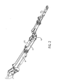
- la figure 2 est une vue partielle de la machine visible sur la figure 1, cette vue montrant la constitution du balancier en trois tronçons ;
- la figure 3 est une vue en perspective schématique et partielle montrant l'assemblage de deux tronçons du balancier;
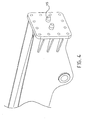
- la figure 4 est une vue en perspective schématique de l'extrémité d'un tronçon après démontage du tronçon voisin ;
- la figure 5 est une vue en perspective schématique prise de l'arrière de la machine après démontage du tronçon central.
- La machine que l'on peut voir sur les dessins permet de réaliser des opérations de fauchage/débroussaillage et d'élagage dans des endroits très divers, bien qu'elle soit plus particulièrement destinée à l'entretien des accotements des routes et autres voies de circulation.
- Elle comprend un véhicule 1, un bâti 2 relié rigidement à l'arrière du véhicule, un bras articulé 3 monté pivotant sur le bâti 2, et un outil de coupe orientable 4 monté à l'extrémité libre du bras articulé 3.
- Dans le mode de réalisation représenté, le bras articulé 3 est constitué d'un bloc pivotant 5, d'une flèche télescopique 6 et d'un balancier 7.
- Selon l'invention, le balancier 7 est un assemblage de trois tronçons 8, 9 et 10, comme le montre la figure 2. Le tronçon 8 situé côté flèche est fixé au tronçon central 9, qui est lui-même fixé au tronçon 10 situé côté outil. Le tronçon central est ici montré équipé d'une articulation 11 actionnée par un vérin hydraulique 12 ; cette articulation supplémentaire permet d'augmenter la portée de travail de l'outil installé à l'extrémité du bras articulé.
- Dans un autre mode de réalisation, le tronçon central 9 peut être équipé d'un système de coulissement avec vérin hydraulique pour le rendre extensible et permettre un réglage supplémentaire de la longueur du bras articulé.
- L'assemblage de deux tronçons adjacents est du type liaison rigide démontable. La figure 3 montre l'assemblage entre deux platines 13 solidaires de l'extrémité de chaque tronçon et sensiblement perpendiculaires à leur longueur, par plusieurs boulons 14 installés à la périphérie de ces platines.
- Pour faciliter le bon positionnement relatif de deux platines contigües, l'une d'elles, montrée sur la figure 4, est équipée de deux pions de centrage 15, cylindriques et parallèles, qui sont engagés, lors de chaque assemblage, dans deux alésages correspondants usinés dans l'autre platine. Cette disposition assure à l'utilisateur l'obtention d'une géométrie correcte à chaque remontage.
- La figure 5 représente la machine après que le tronçon central 9, précédemment montré sur la figure 2, ait été démonté pour raccourcir le balancier 7, et ce faisant, réduire l'encombrement de la machine.
Claims (3)
- Machine pour effectuer des travaux de fauchage/débroussaillage et d'élagage, comprenant un véhicule (1), un bâti (2) attelé au véhicule, un bras articulé (3) monté pivotant sur le bâti et comprenant une flèche (6) et un balancier (7), ainsi qu'un outil de coupe orientable (4) monté à l'extrémité libre du balancier (7), caractérisée en ce que le balancier comprend, entre son extrémité articulée côté flèche et son extrémité articulée côté outil, trois tronçons (8, 9, 10) assemblés bout à bout par des liaisons rigides démontables et dont le tronçon central (9) peut être ajouté ou enlevé afin de modifier l'encombrement et la géométrie du bras articulé (3), et en ce que chaque liaison rigide comprend une platine (13) qui est prévue à l'extrémité de chacun des tronçons destinés à être juxtaposés, et qui est perpendiculaire à la longueur de ceux-ci, les deux platines d'une même liaison rigide étant destinées à être positionnées l'une par rapport à l'autre par deux pions de centrage cylindriques (15) parallèles à la longueur du tronçon central (9), et à être assemblées par plusieurs boulons (14) répartis à leur périphérie ;
- Machine selon la revendication 1, caractérisée en ce que le tronçon amovible (9) comporte une articulation (11) permettant un mouvement supplémentaire du bras articulé (3), et un vérin hydraulique (12) pour actionner cette articulation ;
- Machine selon la revendication 1, caractérisée en ce que le tronçon amovible (9) comporte un réglage de sa longueur par un système de coulissement en translation avec un vérin hydraulique double effet permettant un réglage supplémentaire de la longueur de bras articulé.
Applications Claiming Priority (1)
| Application Number | Priority Date | Filing Date | Title |
|---|---|---|---|
| FR0501977A FR2882499B1 (fr) | 2005-02-25 | 2005-02-25 | Machine de fauchage/debroussaillage et d'elagage a bras articule comprenant un troncon amovible |
Publications (2)
| Publication Number | Publication Date |
|---|---|
| EP1695611A1 true EP1695611A1 (fr) | 2006-08-30 |
| EP1695611B1 EP1695611B1 (fr) | 2009-11-18 |
Family
ID=35241225
Family Applications (1)
| Application Number | Title | Priority Date | Filing Date |
|---|---|---|---|
| EP06290340A Expired - Lifetime EP1695611B1 (fr) | 2005-02-25 | 2006-02-27 | Machine de fauchage/débroussaillage et d'élagage à bras articulé comprenant un tronçon amovible |
Country Status (5)
| Country | Link |
|---|---|
| EP (1) | EP1695611B1 (fr) |
| AT (1) | ATE448675T1 (fr) |
| DE (1) | DE602006010455D1 (fr) |
| ES (1) | ES2336820T3 (fr) |
| FR (1) | FR2882499B1 (fr) |
Families Citing this family (2)
| Publication number | Priority date | Publication date | Assignee | Title |
|---|---|---|---|---|
| FR2942369A1 (fr) * | 2009-02-20 | 2010-08-27 | Signalisation Moderne Autorout | Machine de fauchage/debroussaillage et d'elagage a bras de deport avant reglable |
| ES2811322B2 (es) * | 2019-09-11 | 2021-11-08 | Ramirez Cascales Jose Antonio | Maquina frontal multifunción entre plantas acoplada a tractor (desbrozadora, trituradora y podadora) |
Citations (4)
| Publication number | Priority date | Publication date | Assignee | Title |
|---|---|---|---|---|
| DD41002A (fr) * | ||||
| EP1312251A1 (fr) * | 2001-11-16 | 2003-05-21 | Ferri S.rl. | Agencement hydraulique avec un bras articulé |
| EP1364572A1 (fr) * | 2002-05-15 | 2003-11-26 | Laserjet S.r.l. | Véhicule de débroussailleuse |
| US20040165978A1 (en) * | 2003-02-21 | 2004-08-26 | Deere & Company, A Delaware Corporation | Boom |
-
2005
- 2005-02-25 FR FR0501977A patent/FR2882499B1/fr not_active Expired - Fee Related
-
2006
- 2006-02-27 ES ES06290340T patent/ES2336820T3/es not_active Expired - Lifetime
- 2006-02-27 EP EP06290340A patent/EP1695611B1/fr not_active Expired - Lifetime
- 2006-02-27 DE DE602006010455T patent/DE602006010455D1/de not_active Expired - Lifetime
- 2006-02-27 AT AT06290340T patent/ATE448675T1/de not_active IP Right Cessation
Patent Citations (4)
| Publication number | Priority date | Publication date | Assignee | Title |
|---|---|---|---|---|
| DD41002A (fr) * | ||||
| EP1312251A1 (fr) * | 2001-11-16 | 2003-05-21 | Ferri S.rl. | Agencement hydraulique avec un bras articulé |
| EP1364572A1 (fr) * | 2002-05-15 | 2003-11-26 | Laserjet S.r.l. | Véhicule de débroussailleuse |
| US20040165978A1 (en) * | 2003-02-21 | 2004-08-26 | Deere & Company, A Delaware Corporation | Boom |
Also Published As
| Publication number | Publication date |
|---|---|
| FR2882499A1 (fr) | 2006-09-01 |
| EP1695611B1 (fr) | 2009-11-18 |
| ES2336820T3 (es) | 2010-04-16 |
| FR2882499B1 (fr) | 2008-09-26 |
| ATE448675T1 (de) | 2009-12-15 |
| DE602006010455D1 (de) | 2009-12-31 |
Similar Documents
| Publication | Publication Date | Title |
|---|---|---|
| CA2481311C (fr) | Tete de foration et de boulonnage pour machine de boulonnage | |
| FR2946492A3 (fr) | Coupe-herbe | |
| FR3055082B1 (fr) | Machine agricole comportant un dispositif d'assistance au repliage | |
| EP0740023A1 (fr) | Bras porte-outil à double articulation latérale | |
| EP1370895B1 (fr) | Dispositif de fixation et de reglage d'un organe a supporter | |
| EP1847322B1 (fr) | Dispositif de montage/démontage d'au moins un couteau sur un rotor de machine agricole, et outil equipé d'un tel dispositif | |
| EP1695611B1 (fr) | Machine de fauchage/débroussaillage et d'élagage à bras articulé comprenant un tronçon amovible | |
| EP0700795B1 (fr) | Dispositif de marquage pour la réalisation de signes d'identification à deux dimensions sur la surface d'un objet quelconque | |
| FR2774853A1 (fr) | Organe de coupe pour une machine de coupe notamment une faucheuse | |
| EP0854268A1 (fr) | Disque aubagé à aubes tripodes | |
| EP2426265A1 (fr) | Bras de démolition du type destiné à être relié par une liaison articulée au porteur d'un engin de démolition et engin de démolition équipé d'un tel bras | |
| EP0664241A1 (fr) | Dispositif formant porte-bagages de toit de véhicule automobile | |
| EP4023041B1 (fr) | Support d'outil équipé d'un système d'évitement d'obstacles combinant une articulation à parallélogramme déformable et une articulation pivotante | |
| CH664102A5 (en) | Turning tool with two-headed cutter - has cutter comprising flat symmetrical plate turning on central axis | |
| EP3284333A1 (fr) | Dispositif de montage/demontage d'au moins un marteau sur un rotor de machine agricole, et outil equipe d'un tel dispositif | |
| WO2019211229A1 (fr) | Machine agricole pour la recolte de vegetaux equipee d'un convoyeur | |
| FR2537624A1 (fr) | Pelle pivotante a curer | |
| FR2708491A1 (fr) | Dispositif de préassemblage de deux pièces à sertir. | |
| EP1726389B1 (fr) | Machine-outil avec canon mobile pour la réalisation de pièces par décolletage | |
| EP1205095B1 (fr) | Charrue | |
| FR2942369A1 (fr) | Machine de fauchage/debroussaillage et d'elagage a bras de deport avant reglable | |
| FR2480626A1 (fr) | Dispositif de support orientable pour rampe d'arrosage d'un vehicule de nettoyage de la voirie | |
| FR2856884A1 (fr) | Machine pour la coupe de vegetaux | |
| FR2736504A1 (fr) | Lame de coupe pour debroussailleur rotatif a axe vertical | |
| FR2796241A1 (fr) | Pulveriseur a grande largeur de travail et presentant un encombrement reduit au transport |
Legal Events
| Date | Code | Title | Description |
|---|---|---|---|
| PUAI | Public reference made under article 153(3) epc to a published international application that has entered the european phase |
Free format text: ORIGINAL CODE: 0009012 |
|
| AK | Designated contracting states |
Kind code of ref document: A1 Designated state(s): AT BE BG CH CY CZ DE DK EE ES FI FR GB GR HU IE IS IT LI LT LU LV MC NL PL PT RO SE SI SK TR |
|
| AX | Request for extension of the european patent |
Extension state: AL BA HR MK YU |
|
| 17P | Request for examination filed |
Effective date: 20070118 |
|
| AKX | Designation fees paid |
Designated state(s): AT BE BG CH CY CZ DE DK EE ES FI FR GB GR HU IE IS IT LI LT LU LV MC NL PL PT RO SE SI SK TR |
|
| GRAP | Despatch of communication of intention to grant a patent |
Free format text: ORIGINAL CODE: EPIDOSNIGR1 |
|
| RIN1 | Information on inventor provided before grant (corrected) |
Inventor name: GROUD, LAURENT |
|
| GRAS | Grant fee paid |
Free format text: ORIGINAL CODE: EPIDOSNIGR3 |
|
| GRAA | (expected) grant |
Free format text: ORIGINAL CODE: 0009210 |
|
| AK | Designated contracting states |
Kind code of ref document: B1 Designated state(s): AT BE BG CH CY CZ DE DK EE ES FI FR GB GR HU IE IS IT LI LT LU LV MC NL PL PT RO SE SI SK TR |
|
| REG | Reference to a national code |
Ref country code: GB Ref legal event code: FG4D Free format text: NOT ENGLISH |
|
| REG | Reference to a national code |
Ref country code: CH Ref legal event code: EP |
|
| REG | Reference to a national code |
Ref country code: IE Ref legal event code: FG4D |
|
| REF | Corresponds to: |
Ref document number: 602006010455 Country of ref document: DE Date of ref document: 20091231 Kind code of ref document: P |
|
| REG | Reference to a national code |
Ref country code: NL Ref legal event code: T3 |
|
| REG | Reference to a national code |
Ref country code: ES Ref legal event code: FG2A Ref document number: 2336820 Country of ref document: ES Kind code of ref document: T3 |
|
| LTIE | Lt: invalidation of european patent or patent extension |
Effective date: 20091118 |
|
| PG25 | Lapsed in a contracting state [announced via postgrant information from national office to epo] |
Ref country code: FI Free format text: LAPSE BECAUSE OF FAILURE TO SUBMIT A TRANSLATION OF THE DESCRIPTION OR TO PAY THE FEE WITHIN THE PRESCRIBED TIME-LIMIT Effective date: 20091118 Ref country code: SE Free format text: LAPSE BECAUSE OF FAILURE TO SUBMIT A TRANSLATION OF THE DESCRIPTION OR TO PAY THE FEE WITHIN THE PRESCRIBED TIME-LIMIT Effective date: 20091118 Ref country code: PT Free format text: LAPSE BECAUSE OF FAILURE TO SUBMIT A TRANSLATION OF THE DESCRIPTION OR TO PAY THE FEE WITHIN THE PRESCRIBED TIME-LIMIT Effective date: 20100318 Ref country code: IS Free format text: LAPSE BECAUSE OF FAILURE TO SUBMIT A TRANSLATION OF THE DESCRIPTION OR TO PAY THE FEE WITHIN THE PRESCRIBED TIME-LIMIT Effective date: 20100318 Ref country code: LT Free format text: LAPSE BECAUSE OF FAILURE TO SUBMIT A TRANSLATION OF THE DESCRIPTION OR TO PAY THE FEE WITHIN THE PRESCRIBED TIME-LIMIT Effective date: 20091118 |
|
| PG25 | Lapsed in a contracting state [announced via postgrant information from national office to epo] |
Ref country code: SI Free format text: LAPSE BECAUSE OF FAILURE TO SUBMIT A TRANSLATION OF THE DESCRIPTION OR TO PAY THE FEE WITHIN THE PRESCRIBED TIME-LIMIT Effective date: 20091118 Ref country code: LV Free format text: LAPSE BECAUSE OF FAILURE TO SUBMIT A TRANSLATION OF THE DESCRIPTION OR TO PAY THE FEE WITHIN THE PRESCRIBED TIME-LIMIT Effective date: 20091118 Ref country code: CY Free format text: LAPSE BECAUSE OF FAILURE TO SUBMIT A TRANSLATION OF THE DESCRIPTION OR TO PAY THE FEE WITHIN THE PRESCRIBED TIME-LIMIT Effective date: 20091118 Ref country code: PL Free format text: LAPSE BECAUSE OF FAILURE TO SUBMIT A TRANSLATION OF THE DESCRIPTION OR TO PAY THE FEE WITHIN THE PRESCRIBED TIME-LIMIT Effective date: 20091118 |
|
| REG | Reference to a national code |
Ref country code: IE Ref legal event code: FD4D |
|
| PG25 | Lapsed in a contracting state [announced via postgrant information from national office to epo] |
Ref country code: AT Free format text: LAPSE BECAUSE OF FAILURE TO SUBMIT A TRANSLATION OF THE DESCRIPTION OR TO PAY THE FEE WITHIN THE PRESCRIBED TIME-LIMIT Effective date: 20091118 |
|
| PG25 | Lapsed in a contracting state [announced via postgrant information from national office to epo] |
Ref country code: EE Free format text: LAPSE BECAUSE OF FAILURE TO SUBMIT A TRANSLATION OF THE DESCRIPTION OR TO PAY THE FEE WITHIN THE PRESCRIBED TIME-LIMIT Effective date: 20091118 Ref country code: BG Free format text: LAPSE BECAUSE OF FAILURE TO SUBMIT A TRANSLATION OF THE DESCRIPTION OR TO PAY THE FEE WITHIN THE PRESCRIBED TIME-LIMIT Effective date: 20100218 Ref country code: IE Free format text: LAPSE BECAUSE OF FAILURE TO SUBMIT A TRANSLATION OF THE DESCRIPTION OR TO PAY THE FEE WITHIN THE PRESCRIBED TIME-LIMIT Effective date: 20091118 Ref country code: DK Free format text: LAPSE BECAUSE OF FAILURE TO SUBMIT A TRANSLATION OF THE DESCRIPTION OR TO PAY THE FEE WITHIN THE PRESCRIBED TIME-LIMIT Effective date: 20091118 Ref country code: RO Free format text: LAPSE BECAUSE OF FAILURE TO SUBMIT A TRANSLATION OF THE DESCRIPTION OR TO PAY THE FEE WITHIN THE PRESCRIBED TIME-LIMIT Effective date: 20091118 |
|
| PG25 | Lapsed in a contracting state [announced via postgrant information from national office to epo] |
Ref country code: SK Free format text: LAPSE BECAUSE OF FAILURE TO SUBMIT A TRANSLATION OF THE DESCRIPTION OR TO PAY THE FEE WITHIN THE PRESCRIBED TIME-LIMIT Effective date: 20091118 Ref country code: CZ Free format text: LAPSE BECAUSE OF FAILURE TO SUBMIT A TRANSLATION OF THE DESCRIPTION OR TO PAY THE FEE WITHIN THE PRESCRIBED TIME-LIMIT Effective date: 20091118 |
|
| PLBE | No opposition filed within time limit |
Free format text: ORIGINAL CODE: 0009261 |
|
| STAA | Information on the status of an ep patent application or granted ep patent |
Free format text: STATUS: NO OPPOSITION FILED WITHIN TIME LIMIT |
|
| REG | Reference to a national code |
Ref country code: CH Ref legal event code: PL |
|
| 26N | No opposition filed |
Effective date: 20100819 |
|
| GBPC | Gb: european patent ceased through non-payment of renewal fee |
Effective date: 20100227 |
|
| PG25 | Lapsed in a contracting state [announced via postgrant information from national office to epo] |
Ref country code: LI Free format text: LAPSE BECAUSE OF NON-PAYMENT OF DUE FEES Effective date: 20100228 Ref country code: MC Free format text: LAPSE BECAUSE OF NON-PAYMENT OF DUE FEES Effective date: 20100301 Ref country code: GR Free format text: LAPSE BECAUSE OF FAILURE TO SUBMIT A TRANSLATION OF THE DESCRIPTION OR TO PAY THE FEE WITHIN THE PRESCRIBED TIME-LIMIT Effective date: 20100219 Ref country code: CH Free format text: LAPSE BECAUSE OF NON-PAYMENT OF DUE FEES Effective date: 20100228 |
|
| PG25 | Lapsed in a contracting state [announced via postgrant information from national office to epo] |
Ref country code: IT Free format text: LAPSE BECAUSE OF FAILURE TO SUBMIT A TRANSLATION OF THE DESCRIPTION OR TO PAY THE FEE WITHIN THE PRESCRIBED TIME-LIMIT Effective date: 20091118 Ref country code: GB Free format text: LAPSE BECAUSE OF NON-PAYMENT OF DUE FEES Effective date: 20100227 |
|
| PG25 | Lapsed in a contracting state [announced via postgrant information from national office to epo] |
Ref country code: HU Free format text: LAPSE BECAUSE OF FAILURE TO SUBMIT A TRANSLATION OF THE DESCRIPTION OR TO PAY THE FEE WITHIN THE PRESCRIBED TIME-LIMIT Effective date: 20100519 Ref country code: LU Free format text: LAPSE BECAUSE OF NON-PAYMENT OF DUE FEES Effective date: 20100227 |
|
| PG25 | Lapsed in a contracting state [announced via postgrant information from national office to epo] |
Ref country code: TR Free format text: LAPSE BECAUSE OF FAILURE TO SUBMIT A TRANSLATION OF THE DESCRIPTION OR TO PAY THE FEE WITHIN THE PRESCRIBED TIME-LIMIT Effective date: 20091118 |
|
| REG | Reference to a national code |
Ref country code: FR Ref legal event code: TP Owner name: SMA FAUCHEUX, FR Effective date: 20131021 |
|
| REG | Reference to a national code |
Ref country code: DE Ref legal event code: R082 Ref document number: 602006010455 Country of ref document: DE Representative=s name: V. FUENER EBBINGHAUS FINCK HANO, DE |
|
| REG | Reference to a national code |
Ref country code: DE Ref legal event code: R082 Ref document number: 602006010455 Country of ref document: DE Representative=s name: V. FUENER EBBINGHAUS FINCK HANO, DE Effective date: 20140124 Ref country code: DE Ref legal event code: R081 Ref document number: 602006010455 Country of ref document: DE Owner name: SMA FAUCHEUX, FR Free format text: FORMER OWNER: SIGNALISATION MODERNE AUTOROUTIERE SMA, SAINT CYR EN VAL, FR Effective date: 20140124 |
|
| BECA | Be: change of holder's address |
Owner name: S.M.A. FAUCHEUX28 RUE DU PRESIDENT JF KENNEDY, F-2 Effective date: 20140407 |
|
| BECN | Be: change of holder's name |
Owner name: S.M.A. FAUCHEUX28 RUE DU PRESIDENT JF KENNEDY, F-2 Effective date: 20140407 |
|
| REG | Reference to a national code |
Ref country code: NL Ref legal event code: TD Effective date: 20140502 Ref country code: NL Ref legal event code: SD Effective date: 20140502 |
|
| REG | Reference to a national code |
Ref country code: ES Ref legal event code: PC2A Owner name: SMA FAUCHEUX Effective date: 20140620 |
|
| REG | Reference to a national code |
Ref country code: FR Ref legal event code: PLFP Year of fee payment: 11 |
|
| REG | Reference to a national code |
Ref country code: FR Ref legal event code: PLFP Year of fee payment: 12 |
|
| REG | Reference to a national code |
Ref country code: FR Ref legal event code: PLFP Year of fee payment: 13 |
|
| PGFP | Annual fee paid to national office [announced via postgrant information from national office to epo] |
Ref country code: NL Payment date: 20180112 Year of fee payment: 13 |
|
| PGFP | Annual fee paid to national office [announced via postgrant information from national office to epo] |
Ref country code: DE Payment date: 20180212 Year of fee payment: 13 Ref country code: ES Payment date: 20180327 Year of fee payment: 13 |
|
| PGFP | Annual fee paid to national office [announced via postgrant information from national office to epo] |
Ref country code: BE Payment date: 20180227 Year of fee payment: 13 Ref country code: FR Payment date: 20180226 Year of fee payment: 13 |
|
| REG | Reference to a national code |
Ref country code: DE Ref legal event code: R119 Ref document number: 602006010455 Country of ref document: DE |
|
| REG | Reference to a national code |
Ref country code: NL Ref legal event code: MM Effective date: 20190301 |
|
| REG | Reference to a national code |
Ref country code: BE Ref legal event code: MM Effective date: 20190228 |
|
| PG25 | Lapsed in a contracting state [announced via postgrant information from national office to epo] |
Ref country code: DE Free format text: LAPSE BECAUSE OF NON-PAYMENT OF DUE FEES Effective date: 20190903 Ref country code: NL Free format text: LAPSE BECAUSE OF NON-PAYMENT OF DUE FEES Effective date: 20190301 |
|
| PG25 | Lapsed in a contracting state [announced via postgrant information from national office to epo] |
Ref country code: BE Free format text: LAPSE BECAUSE OF NON-PAYMENT OF DUE FEES Effective date: 20190228 Ref country code: FR Free format text: LAPSE BECAUSE OF NON-PAYMENT OF DUE FEES Effective date: 20190228 |
|
| REG | Reference to a national code |
Ref country code: ES Ref legal event code: FD2A Effective date: 20200331 |
|
| PG25 | Lapsed in a contracting state [announced via postgrant information from national office to epo] |
Ref country code: ES Free format text: LAPSE BECAUSE OF NON-PAYMENT OF DUE FEES Effective date: 20190228 |