EP1694992B1 - Connector assembly for flexible inflatable articles - Google Patents
Connector assembly for flexible inflatable articles Download PDFInfo
- Publication number
- EP1694992B1 EP1694992B1 EP04783560A EP04783560A EP1694992B1 EP 1694992 B1 EP1694992 B1 EP 1694992B1 EP 04783560 A EP04783560 A EP 04783560A EP 04783560 A EP04783560 A EP 04783560A EP 1694992 B1 EP1694992 B1 EP 1694992B1
- Authority
- EP
- European Patent Office
- Prior art keywords
- connector assembly
- washer
- elastomer
- section
- insertable
- Prior art date
- Legal status (The legal status is an assumption and is not a legal conclusion. Google has not performed a legal analysis and makes no representation as to the accuracy of the status listed.)
- Expired - Lifetime
Links
- 238000003780 insertion Methods 0.000 claims abstract description 18
- 230000037431 insertion Effects 0.000 claims abstract description 18
- 239000007788 liquid Substances 0.000 claims description 21
- 229920002635 polyurethane Polymers 0.000 claims description 17
- 239000004814 polyurethane Substances 0.000 claims description 17
- 238000010276 construction Methods 0.000 claims description 13
- 239000000853 adhesive Substances 0.000 claims description 12
- 230000001070 adhesive effect Effects 0.000 claims description 12
- 239000012530 fluid Substances 0.000 claims description 11
- 229920001971 elastomer Polymers 0.000 claims description 9
- 239000000806 elastomer Substances 0.000 claims description 9
- 229920003052 natural elastomer Polymers 0.000 claims description 9
- 229920001194 natural rubber Polymers 0.000 claims description 9
- 229920003051 synthetic elastomer Polymers 0.000 claims description 8
- 238000007789 sealing Methods 0.000 claims description 6
- 244000043261 Hevea brasiliensis Species 0.000 claims description 5
- 238000004891 communication Methods 0.000 claims description 4
- 229920003225 polyurethane elastomer Polymers 0.000 claims description 4
- 229920002379 silicone rubber Polymers 0.000 claims description 4
- 230000037361 pathway Effects 0.000 claims description 3
- 238000004519 manufacturing process Methods 0.000 abstract description 3
- 239000000463 material Substances 0.000 description 21
- 238000005452 bending Methods 0.000 description 4
- 239000004744 fabric Substances 0.000 description 4
- 239000004433 Thermoplastic polyurethane Substances 0.000 description 3
- 230000000712 assembly Effects 0.000 description 3
- 238000000429 assembly Methods 0.000 description 3
- 230000006835 compression Effects 0.000 description 3
- 238000007906 compression Methods 0.000 description 3
- 238000009434 installation Methods 0.000 description 3
- 229920001296 polysiloxane Polymers 0.000 description 3
- 229920002803 thermoplastic polyurethane Polymers 0.000 description 3
- 239000012790 adhesive layer Substances 0.000 description 2
- 238000001816 cooling Methods 0.000 description 2
- 238000013461 design Methods 0.000 description 2
- -1 e.g. Substances 0.000 description 2
- 239000013013 elastic material Substances 0.000 description 2
- 238000010438 heat treatment Methods 0.000 description 2
- 238000000034 method Methods 0.000 description 2
- 239000004745 nonwoven fabric Substances 0.000 description 2
- 229920003023 plastic Polymers 0.000 description 2
- 239000004033 plastic Substances 0.000 description 2
- 238000012360 testing method Methods 0.000 description 2
- 239000004593 Epoxy Substances 0.000 description 1
- JOYRKODLDBILNP-UHFFFAOYSA-N Ethyl urethane Chemical compound CCOC(N)=O JOYRKODLDBILNP-UHFFFAOYSA-N 0.000 description 1
- 229920000544 Gore-Tex Polymers 0.000 description 1
- 229920001400 block copolymer Polymers 0.000 description 1
- 238000007664 blowing Methods 0.000 description 1
- 239000012611 container material Substances 0.000 description 1
- 239000011243 crosslinked material Substances 0.000 description 1
- 230000001419 dependent effect Effects 0.000 description 1
- 230000000694 effects Effects 0.000 description 1
- 239000007789 gas Substances 0.000 description 1
- 239000003292 glue Substances 0.000 description 1
- 239000010410 layer Substances 0.000 description 1
- 238000000465 moulding Methods 0.000 description 1
- 238000004806 packaging method and process Methods 0.000 description 1
- 230000002787 reinforcement Effects 0.000 description 1
- 239000011347 resin Substances 0.000 description 1
- 229920005989 resin Polymers 0.000 description 1
- 230000002441 reversible effect Effects 0.000 description 1
- 238000007655 standard test method Methods 0.000 description 1
- 238000010998 test method Methods 0.000 description 1
Images


Classifications
-
- F—MECHANICAL ENGINEERING; LIGHTING; HEATING; WEAPONS; BLASTING
- F16—ENGINEERING ELEMENTS AND UNITS; GENERAL MEASURES FOR PRODUCING AND MAINTAINING EFFECTIVE FUNCTIONING OF MACHINES OR INSTALLATIONS; THERMAL INSULATION IN GENERAL
- F16K—VALVES; TAPS; COCKS; ACTUATING-FLOATS; DEVICES FOR VENTING OR AERATING
- F16K15/00—Check valves
- F16K15/20—Check valves specially designed for inflatable bodies, e.g. tyres
- F16K15/202—Check valves specially designed for inflatable bodies, e.g. tyres and with flexible valve member
-
- F—MECHANICAL ENGINEERING; LIGHTING; HEATING; WEAPONS; BLASTING
- F16—ENGINEERING ELEMENTS AND UNITS; GENERAL MEASURES FOR PRODUCING AND MAINTAINING EFFECTIVE FUNCTIONING OF MACHINES OR INSTALLATIONS; THERMAL INSULATION IN GENERAL
- F16L—PIPES; JOINTS OR FITTINGS FOR PIPES; SUPPORTS FOR PIPES, CABLES OR PROTECTIVE TUBING; MEANS FOR THERMAL INSULATION IN GENERAL
- F16L47/00—Connecting arrangements or other fittings specially adapted to be made of plastics or to be used with pipes made of plastics
- F16L47/26—Connecting arrangements or other fittings specially adapted to be made of plastics or to be used with pipes made of plastics for branching pipes; for joining pipes to walls; Adaptors therefor
- F16L47/28—Joining pipes to walls or to other pipes, the axis of the joined pipe being perpendicular to the wall or to the axis of the other pipe
- F16L47/30—Joining pipes to walls or to other pipes, the axis of the joined pipe being perpendicular to the wall or to the axis of the other pipe using attaching means embracing the pipe
-
- F—MECHANICAL ENGINEERING; LIGHTING; HEATING; WEAPONS; BLASTING
- F16—ENGINEERING ELEMENTS AND UNITS; GENERAL MEASURES FOR PRODUCING AND MAINTAINING EFFECTIVE FUNCTIONING OF MACHINES OR INSTALLATIONS; THERMAL INSULATION IN GENERAL
- F16L—PIPES; JOINTS OR FITTINGS FOR PIPES; SUPPORTS FOR PIPES, CABLES OR PROTECTIVE TUBING; MEANS FOR THERMAL INSULATION IN GENERAL
- F16L5/00—Devices for use where pipes, cables or protective tubing pass through walls or partitions
- F16L5/02—Sealing
- F16L5/10—Sealing by using sealing rings or sleeves only
Definitions
- the present invention relates to a connector assembly, more particularly to a low profile connector assembly for connecting a source of inflation fluid, e.g., air or liquid, to a flexible inflatable article such as an inflatable garment, an air mattress, a flexible canteen, or other similar-in-principle construction.
- a source of inflation fluid e.g., air or liquid
- a flexible inflatable article such as an inflatable garment, an air mattress, a flexible canteen, or other similar-in-principle construction.
- Inflatable articles which are relatively flexible in use exist for a wide range of applications from air inflatable garments, mattresses, sleeping bags, and the like, to liquid inflatable canteens, bladders, heating/cooling pads, and other similar-in-principle constructions.
- the term inflatable is intended to refer to the ability to create some pressure gradient between the interior and exterior of an article. In certain instances the inflation pressure may be significant (e.g., pressure gradients of 0.07 bar (1.0 psi) or above); however, in other instances only a slight pressure gradient may exist, and the article may be designed to permit air or liquid leakage above some pressure gradient.
- the term flexible is intended to refer to materials having a flexural rigidity, as described in more detail herein, of 50,000 N*m or less, preferably 1000 N*m or less, and most preferably 200 N*m or less.
- Inflatable articles for example, air mattresses, are generally provided with an inflation valve.
- Such valves can be simple plastic tubes affixed to a wall of the inflatable article and having a stop cock affixed thereto. Opening the stop cock allows for deflation of the inflatable article or for inflation through the tube by manual means such as by a person blowing air through the tube and into the inflatable article.
- various types of pumps are available and have been employed to force air into such inflatable articles.
- a bellows pump disclosed in U.S. Patent Application Serial No. 10/230,889 , which is commonly assigned.
- the Patent Application Serial No. 10/230, 889 which is commonly assigned.
- the term air is used for convenience herein; however, it should be appreciated that other suitable gases may be used depending on the specific application of the article.
- collapsible or other suitably flexible canteens and bladders exist typically incorporating screw-on or snap-on fill ports affixed to the collapsible container and extending substantially perpendicular therefrom.
- U.S. Patent Application Publication No. 2003-0106141 is directed to an inflatable, breathable module having one or more inflatable cavities in the module and which further incorporates a pressure relief means for reducing pressure in the inflated portion(s) should the module be subjected to sudden or excessive stress.
- EP 0485362 describes a patient support structure having a number of inflatable sacks.
- the document also describes an inflation assembly for connecting the inflatable sacks to an inflation source.
- the assembly comprises a connection member having a first, generally tubular insertable section, insertable through an adaptor of the sack and a second external pipe extending oppositely from the insertable section and outwardly from the sack upon insertion.
- the external section and the insertable section are connected, the two sections providing a continuous air passageway in to the sack.
- the insertable section has an external circumferential groove there around which, upon insertion into and through said sack adaptor is secured by a sealing ring.
- the ring is stretched into the groove, the ring providing a seal at the adaptor, thereby sealing off leakage of fluid to or from said sack and confining fluid passage to and through the passageway, thereby providing, when assembled, a pathway for fluid communication from the external source into the inflatable sack.
- the present invention provides such an assembly.
- Other advantages of the connector assembly of the invention will become apparent from the following specification.
- a low-profile connector assembly for connecting a flexible inflatable article to a source of inflation fluid, e.g., air or liquid, is provided.
- the assembly includes a semi-rigid, hollow connector housing having a first, generally tubular, insertable section, insertable through an opening in a flexible wall of the inflatable article.
- a second external section extends oppositely from the insertable section and outwardly from the flexible wall upon insertion.
- the external section and the insertable section are connected and oriented generally at an angle with respect to each other (i.e., less than 180 degrees), more preferably at a substantially right angle.
- the two sections provide a continuous air or liquid passageway therethrough into the inflatable article upon insertion therein, the passageway extending from an external opening in the external section, which is removably connectable thereat to a source of inflation air or liquid.
- the passageway extends through the connector assembly and into the inflatable article.
- the insertable section has an external circumferential groove therearound which, upon insertion into and through the flexible wall opening, is secured thereat by an elastic washer positioned immediately adjacent to and concentric with the wall opening.
- the washer may be held against the wall by compression between the wall and the insertable section, or affixed by means of some bond (e.g., adhesive, heat-bonded, etc.) between the wall and the washer, or even integrated with the flexible wall (e.g., molded In, etc.).
- some bond e.g., adhesive, heat-bonded, etc.
- the flexible wall e.g., molded In, etc.
- the washer is press-fit into the groove, thereby providing a seal at the wall opening and sealing off leakage of air to or from the inflatable article and the atmosphere and confining air or liquid passage to and through the passageway.
- a low-profile pathway for fluid communication from an external source into the flexible inflatable article through an opening in a flexible wall thereof is provided.
- the connector assembly preferably further includes a valve which controls flow therethrough.
- the valve may be a one-way check valve, a two-way check valve, a pinch valve , or similar valve construction.
- the connector assembly can be designed to provide a pressure gradient of at least 0.04 bar (0.5 psi), preferably effective to a pressure gradient of at least 0.07 bar (1.0 psi).
- the assembly housing and insertable section preferably are integrally formed into a unitary construction, but the insertable section may be formed as a hollow tubular component having a rim slidably mounted externally thereover, with the rim having an external circumferential groove therearound.
- the elastic washer is affixed to the flexible wall, preferably adhesively, but it may be affixed under heat and pressure or other suitable means. Further, the washer may be affixed by integrally molding it to the flexible wall material.
- the washer is preferably an elastomer, either a natural elastomer or a synthetic elastomer such as a polyurethane elastomer or a silicone elastomer.
- the connector assembly may be used to connect inflatable articles such as garments, including a vest, a jacket, a pant, a coat and similar constructions, a mattress, a sleeping bag, or other flexible articles to a source of inflation air. Additionally, such as connector assembly may be used to connect inflatable articles such as collapsible canteens, bladders, heating/cooling pads and other flexible devices to a source of inflation liquid.
- the connector assembly provides advantages in, for example, ease of assembly, ease in use and relatively low profile of the connector in the finished article relative to prior art devices.
- a low profile connector assembly for connecting a flexible inflatable article such as an inflatable garment, air mattress or collapsible canteen to a source of inflation air or liquid.
- the connector includes a semi-rigid, hollow connector housing having a first, generally tubular, insertable section, insertable through an opening in a flexible wall of the inflatable article.
- a second external section extends oppositely from the insertable section and outwardly from the flexible wall upon insertion, the external section and the insertable section are connected and oriented generally at an angle with respect to each other to create a low profile relative to the article, most preferably the sections are oriented at right angles with respect to each other.
- the two sections provide a continuous air or liquid passageway therethrough into the inflatable article upon insertion therein.
- the passageway extends from an external opening in the external section, and is removably connectable thereat to a source of inflation air or liquid.
- the insertable section has an external circumferential groove therearound which , upon insertion into and through the opening in the flexible wall, is secured thereat by an elastic washer positioned immediately adjacent to and concentric with the wall opening. The washer is press-fit into the groove, providing a seal at the wall opening.
- FIG. 1 is a perspective view of an embodiment of the connector assembly of the invention connecting a small manual pump 32 to an inflatable vest.
- the connector housing 14, exposed externally, is visible in this figure.
- the connector housing 14 is shown in detail in Fig. 2 .
- the housing of this embodiment includes flanged base 17 and grooved insertable section 12 all molded as one piece with the outwardly extending external section 14, which in this external section is shown having a substantially right angle bend therein. It should be appreciated, however, that this external section may have any appropriate angle (i.e., 180° or less) depending on the desired form required by the article. For example, where significant projects from inflatable surfaces are objectionable in use, such right angle sections are preferred.
- Opening 26 is provided for removable connectivity to an external source of air or liquid, for example the manual pump depicted in Fig. 1 .
- the passageway through the connector is depicted by dotted lines and is described in detail below.
- Fig. 3 shows the connector housing 14 viewed from its opposite side to that shown in Fig. 2 .
- Extending from the flanged base 17 is the insertable section 12 opening into the passageway 28 through the housing 14, depicted by dotted lines, to the external inlet 26, adapted to be connected to an inflation air or liquid source.
- Fig. 4 is a cross-sectional view of the connector housing 14 useful in the low profile assembly of this invention.
- the housing 14 comprises a unitary construct having a flanged base 17 which houses a passageway28 extending from an inlet opening 26, through the housing 14, and extending through the internal (inserted) section 12 having circumferential groove 13 therearound.
- the housing 14 in this embodiment is configured such that passageway 28 passes through a substantially right angle bend proceeding from the insertable section 12 through the housing 14 and to the inlet opening 26.
- FIG. 5 One embodiment of the complete connector assembly 10 according to this invention is depicted in cross-section in Fig. 5 .
- the housing 14 having passageway 28, extending from inlet 26 through the housing 14 and through insertable section 12, is inserted into and through opening 16 in the flexible wall 22 of an inflatable construction as shown.
- the opposite wall 24 of the inflatable article is shown for completeness.
- an elastic washer 18 is press-fit over the internal end of insertable section 12 and washer 18 seats within the circumferential groove 13 around the inserted section 12, thereby sealing against passage of air (or liquid) through the opening 16 and confining substantially all air (or liquid) to and through passageway 28.
- the washer 18 may be, and preferably is, secured to the flexible wall 22 and around opening 16 by, for example, an adhesive layer 20, or by other means, such as by heat and pressure or other suitable securing means.
- Fig. 6 shows an exploded view of the connector assembly 10 depicted in Fig. 5 .
- a source of inflation air in this embodiment a reversible pump, is shown schematically connected through a check valve by connection 36 to inlet 26 of the housing 14.
- the passageway 28 through the housing 14 passes through, in this preferred embodiment, a substantially right angle and to the inlet section 12.
- the inlet section 12 is to be inserted through opening 16 in flexible wall 22, indicated by the arrow, and the washer 18 is to be press-fit into the circumferential groove 13 of the inserted section 12, the washer 18 being optionally and preferably secured around the opening 16 of the flexible wall 22 by means of the adhesive layer 20, also all as indicated by the arrows shown.
- the washer 18 When the washer 18 is press-fit onto the insert section 12, the washer 18 must deform to allow the insert section to be inserted. After deforming, the washer must recover to seat into the groove 13. Washer 18 must have the ability to recover after such deformation, i.e., it must be elastic, in order to effect a seal when seated in groove 13.
- a washer which is 100% elastic will seek to recover to its original, predeformed inside diameter (ID). If the outside diameter of the insert is larger than the ID of the washer, a compression seal will result.
- the washer 18 is constructed of an elastic material with a high durometer, it will strongly resist initial deformation, making it harder to install. However, a stronger seal will result upon installation.
- the washer 18 If the washer 18 is made from a material which plastically deforms during installation, it will not fully recover to its original ID. So long as the amount of plastic deformation is small enough to allow for interference stress to be present after installation, a seal will be formed, albeit a weaker seal.
- Elastomer materials are particularly suitable materials for the elastic washer of the invention, in the form of either a natural elastomer such as natural rubber or a synthetic elastomer such as a polyurethane elastomer or a silicone elastomer. Cross-linked elastomer materials are most preferred for longest lifetime performance of the assembly.
- the housing body 14 In the connector assembly of the invention, the housing body 14 must be more rigid than the washer 18. A thick wall of the insertion section 12 will require more force to deform. Taking into account both the material properties of the housing and the washer (durometer, plasticity, stress relaxation) and the geometry of these components, one is able to tailor a connection to meet sealing requirements over a range of differential pressures and duration of effective seals over time.
- Preferred materials of construction for the connector housing 14 will possess a durometer (Shore A) in the range of 50 Shore A or greater, more preferably in the range of 75 to 95 Shore A.
- the washer 18 may comprise any elastomer, preferably one having a durometer of 30 to 70 Shore A, more preferably 50 to 60 Shore A.
- the washer 18 can be a separate component part, as shown and discussed above, or it may be constructed as an integral reinforcement around opening 96 comprising a thicker ring of elastic material surrounding the opening 16.
- the elastic washer 18 is a flat ring washer, which presents a low profile in use, and is made of an elastomer such as block copolymers, polyurethanes, silicones, and natural rubbers, more preferably comprising a polyurethane, and is adhesively bonded to the flexible wall 22 by any suitable adhesive, such as an epoxy, a polyurethane or a silicone.
- a particularly preferred elastic washer/adhesive combination would be a crosslinked polyurethane washer with a reactive polyurethane adhesive.
- the connector assembly of the invention provides a relatively low cost, simple, flexible and low profile design added to the flexible article for use in such inflatable systems as garments, air mattresses, disposables, collapsible canteens, and other wearable/packable products.
- Seals capable of withstanding applied pressures of greater than 0.04 bar (0.5 psi) and exceeding 0.07 bar (1.0 psi), are readily achievable. However, it should be recognized that in certain applications lower applied pressures may exist in the final article.
- the connector assembly of this invention may also be used in constructions such as air mattresses 38 and similar articles.
- the air mattress 38 which is shown in the figure is comprised of individual compartments interconnected by openings 40.
- a small manual air pump 32 is connected via conduit 36 to the mattress 38 through the connector assembly of the invention, of which the housing 14 is visible in the figure.
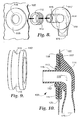
- FIG. 8 the alternate external housing section 114 has an inlet 126, which is adaptable to be connected to a source of air such as a pump, and which opens into through-passageway 128 which extends into the insertion tube 115.
- This insertion tube 115 is generally a cylindrical tube and is either molded integrally with the housing section 114 or is affixed to base 117 by glue or other suitable technique.
- the tube 115 is adapted to accept rim member 112, having circumferential groove 113, slidably thereover. The rim 112 is then adhesively affixed to tube 115 forming the connector housing insert section.
- Fig. 10 specifically depicts the connector assembly 100, through which passageway 128 extends, comprising external housing 114, shown molded integrally with tubular member 115, and having elastic washer 118 bound by adhesive 120 to wall 122, as shown, and seated in groove 113 in rim 112, the rim 112 being adhesively (not shown) affixed to tube 115, all effecting a seal around opening 118 in the wall 122 of an inflatable article.
- Fig. 9 depicts a perspective view of rim 112 having circumferential groove 113 and is included for completeness.
- the housing is preferably constructed of a polyurethane, more preferably a thermoplastic polyurethane.
- the external housing and insertion tube are constructed as separate components, both are preferably made of polyurethane, more preferably thermoplastic polyurethane. It should be appreciated, however, that other suitable materials may be used in the connector assembly, depending on the requirements of the specific application.
- the check valve shown schematically in Fig. 6 may be a one-way check valve, a two-way check valve or a pinch valve, depending on the circumstances of the particular inflatable construction and design preferences.
- a suitable pump or other source of air will be known to those skilled in this art.
- the effectiveness of the seal formed when the elastic washer is seated within the groove of the insertion section is dependent upon the geometry and relative elasticity of the component parts.
- a washer of elastomeric urethane having a center opening inside diameter (ID) of 9.1 mm (0.36 inch) an outside diameter (OD) of 31.8 mm (1.25 inch ), and a thicknes of 3.2 mm (0.125 inch) when press-fit into a groove of OD 11.7 mm (0.46 inch) of a thermoplastic polyurethane insertion section provided a seal to pressure gradient exceeding 1.0 psi between the interior of an inflatable and the atmosphere.
- ID center opening inside diameter
- OD outside diameter
- a thicknes of 3.2 mm (0.125 inch) when press-fit into a groove of OD 11.7 mm (0.46 inch) of a thermoplastic polyurethane insertion section provided a seal to pressure gradient exceeding 1.0 psi between the interior of an inflatable and the atmosphere.
- a preferred adhesive is reactive polyurethane, although other adhesives may be suitable for particular application, and specific adhesives should not limit the scope of the invention in any way.
- Elastic washers useful in the invention may be composed of natural rubbers, synthetic elastomers such as polyurethanes, silicones, etc., and others. Cross-linked forms of these materials often provide desirable advantages such as durability and other expected features of these cross-linked materials which are desirable in the articles of this invention. All such suitably elastic washers are within the scope of the invention.
- the connector assembly of the invention may be used with many types of inflatable flexible articles, Including air mattresses as discussed, garments such as jackets, vests, pants, coats and other similar items, and sleeping bags, to name a few.
- inflatable flexible articles which are Inflated with liquid, such as canteens and the like can be fabricated using the connector assemblies of this invention.
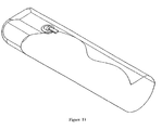
- Figure 11 depicts a connector assembly of the present invention attached to a collapsible canteen.
- Suitable flexible materials for at least the portion of the article wall to which the connector assembly is affixed are those materials having a flexural rigidity, as described in more detail herein, of 50,000 N*m or less, preferably 1000 N*m or less, and most preferably 200 N*m or less.
- Non-limiting examples of materials having these flexibilities include a wide range of fabrics, including wovens and non-wovens, resin impregnated fabrics, elastomeric sheets and other rubber-like materials.
- the flexible articles of the present may comprise some regions containing materials of higher stiffness; however, the inflatable regions of the articles wherein the low profile connector assembly will typically comprise flexible materials.
- the flexibility, or flexural rigidity, of suitable articles to which the connector assemblies of the present invention are attached can be determined using the "Standard Test Method for Stiffness of Nonwoven Fabrics Using the Cantilever Test", Method Number ASTM D5732-95 (Reapproved 2001).
- This test method requires a 25.4 mm (1") wide by 203.2 mm (8") long sample.
- the sample is slid across a horizontal surface at a controlled rate so that one end overhangs the support platform.
- the cantilevered sample bends downward.
- the overhang length is measured.
- the overhang length, sample mass, and sample dimensions are then used to calculate the bending length and the flexural rigidity.
- the flexible connector system of this invention is suitable for use in any article constructed, at least in the region where the connector assembly is to be affixed, of a material having a flexural regidity less than 50,000 N*m, more preferably less than 1000 N*m, and most preferably less than 200 N*m.
- An inflatable jacket was manufactured substantially in accordance with the teachings of Example 1 of U.S. Patent Application Serial No. 10/230,889 , except that the inflation/deflation construct was fabricated in accordance with Figures 1-5 of the present application.
- the washer of the construct comprised a cross-linked polyurethane with a hardness of 55 Shore A.
- the connector of the construct comprised a crosslinked polyurethane with a hardness of 85 Shore A.
Landscapes
- General Engineering & Computer Science (AREA)
- Engineering & Computer Science (AREA)
- Mechanical Engineering (AREA)
- Mattresses And Other Support Structures For Chairs And Beds (AREA)
- Professional, Industrial, Or Sporting Protective Garments (AREA)
- Pipe Accessories (AREA)
- Orthopedics, Nursing, And Contraception (AREA)
- Valve Housings (AREA)
- Self-Closing Valves And Venting Or Aerating Valves (AREA)
- Check Valves (AREA)
- Toys (AREA)
- Lift Valve (AREA)
- Bag Frames (AREA)
Abstract
Description
- The present invention relates to a connector assembly, more particularly to a low profile connector assembly for connecting a source of inflation fluid, e.g., air or liquid, to a flexible inflatable article such as an inflatable garment, an air mattress, a flexible canteen, or other similar-in-principle construction.
- Inflatable articles which are relatively flexible in use exist for a wide range of applications from air inflatable garments, mattresses, sleeping bags, and the like, to liquid inflatable canteens, bladders, heating/cooling pads, and other similar-in-principle constructions. As used herein, the term inflatable is intended to refer to the ability to create some pressure gradient between the interior and exterior of an article. In certain instances the inflation pressure may be significant (e.g., pressure gradients of 0.07 bar (1.0 psi) or above); however, in other instances only a slight pressure gradient may exist, and the article may be designed to permit air or liquid leakage above some pressure gradient. The term flexible is intended to refer to materials having a flexural rigidity, as described in more detail herein, of 50,000 N*m or less, preferably 1000 N*m or less, and most preferably 200 N*m or less.
- Inflatable articles, for example, air mattresses, are generally provided with an inflation valve. Such valves can be simple plastic tubes affixed to a wall of the inflatable article and having a stop cock affixed thereto. Opening the stop cock allows for deflation of the inflatable article or for inflation through the tube by manual means such as by a person blowing air through the tube and into the inflatable article. Alternatively, various types of pumps are available and have been employed to force air into such inflatable articles. Especially suited for inflatable garments and the like is a bellows pump disclosed in
U.S. Patent Application Serial No. 10/230,889 , which is commonly assigned. The Patent Application Serial No.10/230, 889 - In the case of liquid inflatable articles, collapsible or other suitably flexible canteens and bladders exist typically incorporating screw-on or snap-on fill ports affixed to the collapsible container and extending substantially perpendicular therefrom.
- Pressure relief valves incorporated into inflatable articles, such as garments and the like have been taught.
U.S. Patent Application Publication No. 2003-0106141 is directed to an inflatable, breathable module having one or more inflatable cavities in the module and which further incorporates a pressure relief means for reducing pressure in the inflated portion(s) should the module be subjected to sudden or excessive stress. -
EP 0485362 describes a patient support structure having a number of inflatable sacks. The document also describes an inflation assembly for connecting the inflatable sacks to an inflation source. The assembly comprises a connection member having a first, generally tubular insertable section, insertable through an adaptor of the sack and a second external pipe extending oppositely from the insertable section and outwardly from the sack upon insertion. The external section and the insertable section are connected, the two sections providing a continuous air passageway in to the sack. The insertable section has an external circumferential groove there around which, upon insertion into and through said sack adaptor is secured by a sealing ring. The ring is stretched into the groove, the ring providing a seal at the adaptor, thereby sealing off leakage of fluid to or from said sack and confining fluid passage to and through the passageway, thereby providing, when assembled, a pathway for fluid communication from the external source into the inflatable sack. - A need has existed for an improved assembly for a flexible inflatable article which provides ease of connection and disassembly from an external inflation source, is relatively simple to incorporate in a continuous manufacturing operation, presents a low profile during manufacturing and in use when affixed to a flexible inflatable article, and which further incorporates a pressure relief means. The present invention provides such an assembly. Other advantages of the connector assembly of the invention will become apparent from the following specification.
- A low-profile connector assembly for connecting a flexible inflatable article to a source of inflation fluid, e.g., air or liquid, is provided. The assembly includes a semi-rigid, hollow connector housing having a first, generally tubular, insertable section, insertable through an opening in a flexible wall of the inflatable article. A second external section extends oppositely from the insertable section and outwardly from the flexible wall upon insertion. The external section and the insertable section are connected and oriented generally at an angle with respect to each other (i.e., less than 180 degrees), more preferably at a substantially right angle. The two sections provide a continuous air or liquid passageway therethrough into the inflatable article upon insertion therein, the passageway extending from an external opening in the external section, which is removably connectable thereat to a source of inflation air or liquid. The passageway extends through the connector assembly and into the inflatable article. The insertable section has an external circumferential groove therearound which, upon insertion into and through the flexible wall opening, is secured thereat by an elastic washer positioned immediately adjacent to and concentric with the wall opening. By positioned it is meant that the washer may be held against the wall by compression between the wall and the insertable section, or affixed by means of some bond (e.g., adhesive, heat-bonded, etc.) between the wall and the washer, or even integrated with the flexible wall (e.g., molded In, etc.).
- The washer is press-fit into the groove, thereby providing a seal at the wall opening and sealing off leakage of air to or from the inflatable article and the atmosphere and confining air or liquid passage to and through the passageway. When assembled, a low-profile pathway for fluid communication from an external source into the flexible inflatable article through an opening in a flexible wall thereof is provided.
- The connector assembly preferably further includes a valve which controls flow therethrough. The valve may be a one-way check valve, a two-way check valve, a pinch valve , or similar valve construction.
- In one preferred embodiment for air inflation of an inflatable article, the connector assembly can be designed to provide a pressure gradient of at least 0.04 bar (0.5 psi), preferably effective to a pressure gradient of at least 0.07 bar (1.0 psi).
- The assembly housing and insertable section preferably are integrally formed into a unitary construction, but the insertable section may be formed as a hollow tubular component having a rim slidably mounted externally thereover, with the rim having an external circumferential groove therearound.
- In a further preferred embodiment, the elastic washer is affixed to the flexible wall, preferably adhesively, but it may be affixed under heat and pressure or other suitable means. Further, the washer may be affixed by integrally molding it to the flexible wall material. The washer is preferably an elastomer, either a natural elastomer or a synthetic elastomer such as a polyurethane elastomer or a silicone elastomer.
- The connector assembly may be used to connect inflatable articles such as garments, including a vest, a jacket, a pant, a coat and similar constructions, a mattress, a sleeping bag, or other flexible articles to a source of inflation air. Additionally, such as connector assembly may be used to connect inflatable articles such as collapsible canteens, bladders, heating/cooling pads and other flexible devices to a source of inflation liquid. The connector assembly provides advantages in, for example, ease of assembly, ease in use and relatively low profile of the connector in the finished article relative to prior art devices.
- In the accompanying drawings:
-
Fig. 1 depicts the low profile connector assembly of the present invention connecting a small manual air pump to the inlet opening of an inflatable garment, specifically an inflatable vest. -
Fig. 2 shows a top perspective view of one embodiment of the connector housing. -
Fig. 3 shows a bottom perspective view of the connector housing ofFig. 2 . -
Fig 4 . is a cross-sectional view of an embodiment of the connector housing according to the invention. -
Fig. 5 is a cross-sectional view of a connector assembly according to the invention, connected to the flexible wall of an inflatable construction such as an inflatable garment, air mattress or collapsible canteen. -
Fig. 6 is an exploded view of the connector assembly, including an auxiliary check valve and pump, shown schematically, according to the invention. -
Fig. 7 depicts the low profile connector assembly of the invention connecting a small air pump to the inlet port of an inflatable air mattress. -
Fig. 8 is an exploded view of an alternative embodiment of the connector of the invention. -
Fig. 9 is a perspective view of a rim having a groove, which rim is employed in securing the alternate connector assembly to the connector housing. -
Fig. 10 is a cross-sectional view of the alternate connector assembly including the connector housing, separate grooved rim and securing washer all connected together. -
Figure 11 depicts the low profile connector assembly of the invention connecting a liquid fill valve to the inlet port of a collapsible canteen. - A low profile connector assembly is provided for connecting a flexible inflatable article such as an inflatable garment, air mattress or collapsible canteen to a source of inflation air or liquid. The connector includes a semi-rigid, hollow connector housing having a first, generally tubular, insertable section, insertable through an opening in a flexible wall of the inflatable article. A second external section extends oppositely from the insertable section and outwardly from the flexible wall upon insertion, the external section and the insertable section are connected and oriented generally at an angle with respect to each other to create a low profile relative to the article, most preferably the sections are oriented at right angles with respect to each other. The two sections provide a continuous air or liquid passageway therethrough into the inflatable article upon insertion therein. The passageway extends from an external opening in the external section, and is removably connectable thereat to a source of inflation air or liquid. The insertable section has an external circumferential groove therearound which , upon insertion into and through the opening in the flexible wall, is secured thereat by an elastic washer positioned immediately adjacent to and concentric with the wall opening. The washer is press-fit into the groove, providing a seal at the wall opening.
- A detailed description of the invention and preferred embodiments is best provided with reference to the accompanying drawings wherein
Fig. 1 is a perspective view of an embodiment of the connector assembly of the invention connecting a smallmanual pump 32 to an inflatable vest. Theconnector housing 14, exposed externally, is visible in this figure. - The
connector housing 14 is shown in detail inFig. 2 . The housing of this embodiment includesflanged base 17 and groovedinsertable section 12 all molded as one piece with the outwardly extendingexternal section 14, which in this external section is shown having a substantially right angle bend therein. It should be appreciated, however, that this external section may have any appropriate angle (i.e., 180° or less) depending on the desired form required by the article. For example, where significant projects from inflatable surfaces are objectionable in use, such right angle sections are preferred.Opening 26 is provided for removable connectivity to an external source of air or liquid, for example the manual pump depicted inFig. 1 . The passageway through the connector is depicted by dotted lines and is described in detail below. -
Fig. 3 shows theconnector housing 14 viewed from its opposite side to that shown inFig. 2 . Extending from theflanged base 17 is theinsertable section 12 opening into thepassageway 28 through thehousing 14, depicted by dotted lines, to theexternal inlet 26, adapted to be connected to an inflation air or liquid source. -
Fig. 4 is a cross-sectional view of theconnector housing 14 useful in the low profile assembly of this invention. Therein, thehousing 14 comprises a unitary construct having aflanged base 17 which houses a passageway28 extending from aninlet opening 26, through thehousing 14, and extending through the internal (inserted)section 12 having circumferential groove 13 therearound. Thehousing 14 in this embodiment is configured such thatpassageway 28 passes through a substantially right angle bend proceeding from theinsertable section 12 through thehousing 14 and to theinlet opening 26. - One embodiment of the
complete connector assembly 10 according to this invention is depicted in cross-section inFig. 5 . Therein thehousing 14 havingpassageway 28, extending frominlet 26 through thehousing 14 and throughinsertable section 12, is inserted into and through opening 16 in theflexible wall 22 of an inflatable construction as shown. Theopposite wall 24 of the inflatable article is shown for completeness. To secure theconnector housing 14 in its inserted configuration, anelastic washer 18 is press-fit over the internal end ofinsertable section 12 andwasher 18 seats within thecircumferential groove 13 around the insertedsection 12, thereby sealing against passage of air (or liquid) through theopening 16 and confining substantially all air (or liquid) to and throughpassageway 28. To further ensure against air or liquid leakage, thewasher 18 may be, and preferably is, secured to theflexible wall 22 and around opening 16 by, for example, anadhesive layer 20, or by other means, such as by heat and pressure or other suitable securing means. -
Fig. 6 shows an exploded view of theconnector assembly 10 depicted inFig. 5 . InFig. 6 , a source of inflation air, in this embodiment a reversible pump, is shown schematically connected through a check valve byconnection 36 toinlet 26 of thehousing 14. Thepassageway 28 through the housing 14 (depicted by dotted lines) passes through, in this preferred embodiment, a substantially right angle and to theinlet section 12. Theinlet section 12 is to be inserted through opening 16 inflexible wall 22, indicated by the arrow, and thewasher 18 is to be press-fit into thecircumferential groove 13 of the insertedsection 12, thewasher 18 being optionally and preferably secured around theopening 16 of theflexible wall 22 by means of theadhesive layer 20, also all as indicated by the arrows shown. - When the
washer 18 is press-fit onto theinsert section 12, thewasher 18 must deform to allow the insert section to be inserted. After deforming, the washer must recover to seat into thegroove 13.Washer 18 must have the ability to recover after such deformation, i.e., it must be elastic, in order to effect a seal when seated ingroove 13. - A washer which is 100% elastic will seek to recover to its original, predeformed inside diameter (ID). If the outside diameter of the insert is larger than the ID of the washer, a compression seal will result.
- If the
washer 18 is constructed of an elastic material with a high durometer, it will strongly resist initial deformation, making it harder to install. However, a stronger seal will result upon installation. - If the
washer 18 is made from a material which plastically deforms during installation, it will not fully recover to its original ID. So long as the amount of plastic deformation is small enough to allow for interference stress to be present after installation, a seal will be formed, albeit a weaker seal. - Some materials which are initially elastic will "stress relax" over time. For those, a seal may be formed initially to an acceptable level, but, after time, the seal will weaken to a point where there is no effective seal at pressure. The washer material must therefore be chosen to maintain an acceptable seal over its expected lifetime. Elastomer materials are particularly suitable materials for the elastic washer of the invention, in the form of either a natural elastomer such as natural rubber or a synthetic elastomer such as a polyurethane elastomer or a silicone elastomer. Cross-linked elastomer materials are most preferred for longest lifetime performance of the assembly.
- In the connector assembly of the invention, the
housing body 14 must be more rigid than thewasher 18. A thick wall of theinsertion section 12 will require more force to deform. Taking into account both the material properties of the housing and the washer (durometer, plasticity, stress relaxation) and the geometry of these components, one is able to tailor a connection to meet sealing requirements over a range of differential pressures and duration of effective seals over time. - Preferred materials of construction for the
connector housing 14 will possess a durometer (Shore A) in the range of 50 Shore A or greater, more preferably in the range of 75 to 95 Shore A. Thewasher 18 may comprise any elastomer, preferably one having a durometer of 30 to 70 Shore A, more preferably 50 to 60 Shore A. - The
elastic washer 18, when properly seated ingroove 13, is in circumferential tension, resulting in a radially inwardly directed compression force which forms a seal capable of withstanding a pressure gradient. Thewasher 18 can be a separate component part, as shown and discussed above, or it may be constructed as an integral reinforcement around opening 96 comprising a thicker ring of elastic material surrounding theopening 16. - Preferably, the
elastic washer 18 is a flat ring washer, which presents a low profile in use, and is made of an elastomer such as block copolymers, polyurethanes, silicones, and natural rubbers, more preferably comprising a polyurethane, and is adhesively bonded to theflexible wall 22 by any suitable adhesive, such as an epoxy, a polyurethane or a silicone. For example, a particularly preferred elastic washer/adhesive combination would be a crosslinked polyurethane washer with a reactive polyurethane adhesive. These low profile and flexible features of the washer sallow for ease of packaging and handling of the flexible inflatable construction with the washer Installed thereon. - The connector assembly of the invention provides a relatively low cost, simple, flexible and low profile design added to the flexible article for use in such inflatable systems as garments, air mattresses, disposables, collapsible canteens, and other wearable/packable products. Seals capable of withstanding applied pressures of greater than 0.04 bar (0.5 psi) and exceeding 0.07 bar (1.0 psi), are readily achievable. However, it should be recognized that in certain applications lower applied pressures may exist in the final article.
- As shown in
Fig. 7 , the connector assembly of this invention may also be used in constructions such asair mattresses 38 and similar articles. Theair mattress 38 which is shown in the figure is comprised of individual compartments interconnected byopenings 40. A smallmanual air pump 32 is connected viaconduit 36 to themattress 38 through the connector assembly of the invention, of which thehousing 14 is visible in the figure. - One possible
alternative embodiment 100 of the connector assembly on the invention is shown inFigs. 8-10 . InFig. 8 , the alternateexternal housing section 114 has aninlet 126, which is adaptable to be connected to a source of air such as a pump, and which opens into through-passageway 128 which extends into theinsertion tube 115. Thisinsertion tube 115 is generally a cylindrical tube and is either molded integrally with thehousing section 114 or is affixed to base 117 by glue or other suitable technique. Thetube 115 is adapted to acceptrim member 112, havingcircumferential groove 113, slidably thereover. Therim 112 is then adhesively affixed totube 115 forming the connector housing insert section. The rim 192 andtube 115 assembly is then press-fit, as indicated by the arrow, into and through the center opening 116 of the wall, around which is secured, by adhesive or other means, theelastic washer 118, thereby completing the connector assembly. This assembly is shown in cross-sectional detail inFig. 10. Fig. 10 specifically depicts theconnector assembly 100, through whichpassageway 128 extends, comprisingexternal housing 114, shown molded integrally withtubular member 115, and havingelastic washer 118 bound by adhesive 120 towall 122, as shown, and seated ingroove 113 inrim 112, therim 112 being adhesively (not shown) affixed totube 115, all effecting a seal aroundopening 118 in thewall 122 of an inflatable article.Fig. 9 depicts a perspective view ofrim 112 havingcircumferential groove 113 and is included for completeness. - In the construction of the connector assembly of the invention, the housing is preferably constructed of a polyurethane, more preferably a thermoplastic polyurethane. Where the external housing and insertion tube are constructed as separate components, both are preferably made of polyurethane, more preferably thermoplastic polyurethane. It should be appreciated, however, that other suitable materials may be used in the connector assembly, depending on the requirements of the specific application.
- The check valve shown schematically in
Fig. 6 may be a one-way check valve, a two-way check valve or a pinch valve, depending on the circumstances of the particular inflatable construction and design preferences. A suitable pump or other source of air will be known to those skilled in this art. - The effectiveness of the seal formed when the elastic washer is seated within the groove of the insertion section is dependent upon the geometry and relative elasticity of the component parts. As an example, a washer of elastomeric urethane having a center opening inside diameter (ID) of 9.1 mm (0.36 inch) an outside diameter (OD) of 31.8 mm (1.25 inch ), and a thicknes of 3.2 mm (0.125 inch) when press-fit into a groove of OD 11.7 mm (0.46 inch) of a thermoplastic polyurethane insertion section provided a seal to pressure gradient exceeding 1.0 psi between the interior of an inflatable and the atmosphere. One skilled in this art will readily appreciate that effective seals may be achieved over a wide range of pressure gradients using the principles of the invention set forth herein.
- Certain assemblies described above include adhesive bonds between components. A preferred adhesive is reactive polyurethane, although other adhesives may be suitable for particular application, and specific adhesives should not limit the scope of the invention in any way.
- Elastic washers useful in the invention may be composed of natural rubbers, synthetic elastomers such as polyurethanes, silicones, etc., and others. Cross-linked forms of these materials often provide desirable advantages such as durability and other expected features of these cross-linked materials which are desirable in the articles of this invention. All such suitably elastic washers are within the scope of the invention.
- The connector assembly of the invention may be used with many types of inflatable flexible articles, Including air mattresses as discussed, garments such as jackets, vests, pants, coats and other similar items, and sleeping bags, to name a few. In addition, inflatable flexible articles which are Inflated with liquid, such as canteens and the like, can be fabricated using the connector assemblies of this invention.
Figure 11 depicts a connector assembly of the present invention attached to a collapsible canteen. - Suitable flexible materials for at least the portion of the article wall to which the connector assembly is affixed are those materials having a flexural rigidity, as described in more detail herein, of 50,000 N*m or less, preferably 1000 N*m or less, and most preferably 200 N*m or less. Non-limiting examples of materials having these flexibilities include a wide range of fabrics, including wovens and non-wovens, resin impregnated fabrics, elastomeric sheets and other rubber-like materials. The flexible articles of the present may comprise some regions containing materials of higher stiffness; however, the inflatable regions of the articles wherein the low profile connector assembly will typically comprise flexible materials.
- Embodiments of the present invention will now be described by way of example only with reference to the following examples.
- The flexibility, or flexural rigidity, of suitable articles to which the connector assemblies of the present invention are attached can be determined using the "Standard Test Method for Stiffness of Nonwoven Fabrics Using the Cantilever Test", Method Number ASTM D5732-95 (Reapproved 2001).
- This test method requires a 25.4 mm (1") wide by 203.2 mm (8") long sample. The sample is slid across a horizontal surface at a controlled rate so that one end overhangs the support platform. As the sample slides across the support platform and the overhang length increases, the cantilevered sample bends downward. When the downward bend angle reaches 0.785 radians (41.5°), the overhang length is measured. The overhang length, sample mass, and sample dimensions are then used to calculate the bending length and the flexural rigidity.
- The results for several flexible wall materials useful for atachment of the connector assembly of this invention are given in Table 1 below. The more flexible the material, the lower the bending length and the lower the flexural rigidity.
TABLE 1 - BENDING LENGTH/FLEXURAL RIGIDITY (ASTM D5732) Container Material Bending length (mm) Flexural Rigidity
(N*m)Versollan RU 2204 70.0 38071 (GLS Corporation, McHenry, IL) 2-layer Gore-Tex® laminate 23.0 93 GORE® Laminate # ECAT 001000B 16.5 73 - The flexible connector system of this invention is suitable for use in any article constructed, at least in the region where the connector assembly is to be affixed, of a material having a flexural regidity less than 50,000 N*m, more preferably less than 1000 N*m, and most preferably less than 200 N*m.
- An inflatable jacket was manufactured substantially in accordance with the teachings of Example 1 of
U.S. Patent Application Serial No. 10/230,889 , except that the inflation/deflation construct was fabricated in accordance withFigures 1-5 of the present application. The washer of the construct comprised a cross-linked polyurethane with a hardness of 55 Shore A. The connector of the construct comprised a crosslinked polyurethane with a hardness of 85 Shore A. To insert the inflation/deflation construct, as noted in 10/230,889, a hole was cut in one of the fabric panels and the construct was attached. The inflation/deflation construct was bonded to the fabric panel using a polyurethane adhesive.
Claims (26)
- A connector assembly (10) for connecting an inflatable article to an inflation source, the assembly comprising:an elastic washer (18);a semi-rigid, hollow connector housing (14) having a first, generally tubular, insertable section (12), insertable through an opening (16) in a flexible wall (22) of said inflatable article, and a second external section extending oppositely from the insertable section and outwardly from said flexible wall upon insertion, the external section and the insertable section being connected, the two sections providing a continuous air passageway (28) therethrough into the inflatable article upon insertion therein, said passageway extending from an external opening (26) in said external section and being removably connectable thereat to said source of inflation fluid, through the connector assembly, and into the inflatable article,wherein said insertable section has an external circumferential groove (13) therearound which, upon insertion into and through said wall opening, is secured thereat by the elastic washer (18) positioned immediately adjacent to and concentric with said wall opening in use, said washer being press-fit into said groove, the washer providing a seal at said wall opening, thereby sealing off leakage of fluid to or from said inflatable article and confining fluid passage to and through said passageway, thereby providing, when assembled, a low-profile pathway for fluid communication from said external source into said inflatable article through a wall opening thereof,wherein the second external section includes a flanged base (17;117), so that the flexible wall (22) is positioned in use between the elastic washer and the flanged base (17; 117).
- The connector assembly of claim 1, including a valve installed in fluid communication with the air in said passageway, which valve controls flow therethrough.
- The connector assembly of claim 2, wherein said valve is a one-way check valve, a two-way check valve, or a pinch valve.
- The connector assembly of claim 1, providing a seal effective to a pressure gradient of at least 0.04 bar (0.5 psi), or at least 0.07 bar (1.0 psi).
- The connector assembly of claim 1, wherein the housing and insertable section are integrally formed into a unitary construction.
- The connector assembly of claim 1, wherein said insertable section (114) is formed as a hollow tubular component having a rim (112) slidably mounted externally thereover, said rim having an external circumferential groove (113) therearound.
- The connector assembly of claim 6, wherein said rim is mounted on said tubular component and adhesively affixed thereto.
- The connector assembly of claim 1, wherein said washer is affixable to said wall.
- The connector assembly of claim 8, wherein said washer is adhesively affixable to said wall.
- The connector assembly of claim 9, wherein the adhesive is polyurethane.
- The connector assembly of claim 11, wherein said washer is affixable under heat and pressure.
- The connector assembly of claim 1, wherein, in use, said washer is integrally mouldable into said wall.
- The connector assembly of claim 1, wherein said housing is polyurethane.
- The connector assembly of claim 1, wherein said insertable section is polyurethane.
- The connector assembly of claim 1, wherein said washer is an elastomer, synthetic elastomer, or crosslinked synthetic elastomer.
- The connector assembly of claim 1, wherein said washer is an elastomer and said elastomer is a natural elastomer, preferably a natural rubber.
- The connector assembly of claim 1, wherein said washer is a synthetic elastomer and said synthetic elastomer is a polyurethane elastomer or silicone elastomer.
- The connector assembly of claim 1, wherein, in use, said inflatable article is a garment, a vest, a jacket, a sleeping bag, or a canteen.
- The connector assembly of claim 1, further comprising a source of inflation air or inflation liquid.
- The connector assembly of claim 1, wherein the external section and the insertable section are oriented at substantially a right angle with respect to each other.
- The connector assembly of claim 20, wherein said housing is polyurethane.
- The connector assembly of claim 20, wherein said insertable section is polyurethane.
- The connector assembly of claim 20, wherein said washer is an elastomer, a natural elastomer, or natural rubber.
- The connector assembly of claim 20, wherein said washer is a synthetic elastomer, a polyurethane elastomer, or a silicone elastomer.
- The connector assembly of claim 20, wherein, in use, said inflatable article is a garment, a vest, a jacket, a pant, a coat, a mattress, a sleeping bag, or a canteen.
- The connector assembly of claim 20, further comprising a source of inflation air or inflation liquid.
Applications Claiming Priority (2)
| Application Number | Priority Date | Filing Date | Title |
|---|---|---|---|
| US10/742,615 US20050046182A1 (en) | 2003-08-25 | 2003-12-18 | Connector assembly for flexible inflatable articles |
| PCT/US2004/029350 WO2005068882A1 (en) | 2003-12-18 | 2004-08-30 | Connector assembly for flexible inflatable articles |
Publications (2)
| Publication Number | Publication Date |
|---|---|
| EP1694992A1 EP1694992A1 (en) | 2006-08-30 |
| EP1694992B1 true EP1694992B1 (en) | 2009-10-07 |
Family
ID=34794630
Family Applications (1)
| Application Number | Title | Priority Date | Filing Date |
|---|---|---|---|
| EP04783560A Expired - Lifetime EP1694992B1 (en) | 2003-12-18 | 2004-08-30 | Connector assembly for flexible inflatable articles |
Country Status (8)
| Country | Link |
|---|---|
| US (1) | US20050046182A1 (en) |
| EP (1) | EP1694992B1 (en) |
| JP (1) | JP2007514910A (en) |
| CN (1) | CN1894528B (en) |
| AT (2) | ATE445116T1 (en) |
| CA (1) | CA2549336C (en) |
| DE (2) | DE602004018681D1 (en) |
| WO (1) | WO2005068882A1 (en) |
Families Citing this family (18)
| Publication number | Priority date | Publication date | Assignee | Title |
|---|---|---|---|---|
| US8404341B2 (en) | 2006-01-26 | 2013-03-26 | Outlast Technologies, LLC | Microcapsules and other containment structures for articles incorporating functional polymeric phase change materials |
| US20100012883A1 (en) * | 2008-07-16 | 2010-01-21 | Outlast Technologies, Inc. | Functional Polymeric Phase Change Materials |
| US20100016513A1 (en) * | 2008-07-16 | 2010-01-21 | Outlast Technologies, Inc. | Functional Polymeric Phase Change Materials and Methods of Manufacturing the Same |
| US9234059B2 (en) * | 2008-07-16 | 2016-01-12 | Outlast Technologies, LLC | Articles containing functional polymeric phase change materials and methods of manufacturing the same |
| US20070173154A1 (en) * | 2006-01-26 | 2007-07-26 | Outlast Technologies, Inc. | Coated articles formed of microcapsules with reactive functional groups |
| US20080148472A1 (en) * | 2006-12-20 | 2008-06-26 | Maryann Cline | Bath tub cushion |
| US20100015430A1 (en) * | 2008-07-16 | 2010-01-21 | Outlast Technologies, Inc. | Heat Regulating Article With Moisture Enhanced Temperature Control |
| US8221910B2 (en) | 2008-07-16 | 2012-07-17 | Outlast Technologies, LLC | Thermal regulating building materials and other construction components containing polymeric phase change materials |
| US8845562B2 (en) * | 2010-07-21 | 2014-09-30 | Hill-Rom Services, Inc. | Gas supply system |
| CN102370265B (en) * | 2010-08-20 | 2013-07-03 | 邱金益 | Clothing device with cooling and warming effect |
| US8673448B2 (en) | 2011-03-04 | 2014-03-18 | Outlast Technologies Llc | Articles containing precisely branched functional polymeric phase change materials |
| CN104395113B (en) * | 2012-06-18 | 2017-03-08 | 巴斯夫欧洲公司 | Valve for inflatable hose part |
| GB2503912B (en) | 2012-07-11 | 2015-12-02 | Pneuma Pure I P Ltd | A cushioning device inspection port, a device for inspection of a cushioning device and a cushioning device inspection method |
| US10431858B2 (en) | 2015-02-04 | 2019-10-01 | Global Web Horizons, Llc | Systems, structures and materials for electrochemical device thermal management |
| US10003053B2 (en) | 2015-02-04 | 2018-06-19 | Global Web Horizons, Llc | Systems, structures and materials for electrochemical device thermal management |
| EP3026318B1 (en) * | 2015-12-23 | 2018-02-14 | TI Automotive (Fuldabrück) GmbH | Connector with mounting aid and method for producing a connector |
| CN111465681B (en) * | 2017-12-21 | 2024-04-05 | 环球生命科技咨询美国有限责任公司 | Fluid port |
| US11707139B2 (en) | 2021-11-04 | 2023-07-25 | Huaao (Quzhou) Outdoor Products Co., Ltd. | Sleeping pad with fast-inflation and deflation air nozzle |
Family Cites Families (15)
| Publication number | Priority date | Publication date | Assignee | Title |
|---|---|---|---|---|
| GB426786A (en) * | 1934-08-23 | 1935-04-10 | James Benson | Improvements in valves or closures for pneumatic vessels |
| US2039009A (en) * | 1935-02-01 | 1936-04-28 | Gen Motors Corp | Grommet or the like |
| US2064695A (en) * | 1935-06-11 | 1936-12-15 | Nathaniel L Foster | Air valve |
| US2180960A (en) * | 1938-07-26 | 1939-11-21 | Benjamin H Kennedy | Nipple structure |
| US2374796A (en) * | 1942-05-18 | 1945-05-01 | Universal Paper Products Compa | Collapsible container |
| US2889089A (en) * | 1956-03-16 | 1959-06-02 | Coleman Co | Plastic coupling structures and drain |
| US3699589A (en) * | 1968-08-05 | 1972-10-24 | Ilc Ind Inc | Spacesuit thigh restraint assembly |
| SE408999B (en) * | 1977-11-18 | 1979-07-23 | Gambro Ab | SEALING DEVICE |
| US4745647A (en) * | 1985-12-30 | 1988-05-24 | Ssi Medical Services, Inc. | Patient support structure |
| US4732415A (en) * | 1986-08-29 | 1988-03-22 | The Boeing Company | Non-metallic vacuum probe |
| DE8904832U1 (en) * | 1989-04-17 | 1989-06-01 | John Gmbh, 8228 Freilassing | Inflation valve, especially for inflatable items |
| US5273110A (en) * | 1992-07-22 | 1993-12-28 | Fitzgibbon Jr Daniel F | Inflatable devices for suspending explosives and stemming materials in boreholes |
| IT1270028B (en) * | 1994-03-09 | 1997-04-28 | Leonelli Paolo | CONDUCT WITH DISPENSES OF DELIVERED FLUID, ESPECIALLY FOR PLANTS FOR THE CONDITIONING OF CIVIL INDUSTRIAL ENVIRONMENTS |
| US5551590A (en) * | 1995-05-30 | 1996-09-03 | Amtrol Inc. | Non-metallic pressure vessel fitting |
| US6467820B1 (en) * | 1998-10-23 | 2002-10-22 | David E. Albrecht | High-pressure fluid-flow system having compact two-bolt and four-bolt flanged and modular connectors |
-
2003
- 2003-12-18 US US10/742,615 patent/US20050046182A1/en not_active Abandoned
-
2004
- 2004-08-30 JP JP2006545327A patent/JP2007514910A/en active Pending
- 2004-08-30 AT AT04783560T patent/ATE445116T1/en not_active IP Right Cessation
- 2004-08-30 CN CN200480037501.1A patent/CN1894528B/en not_active Expired - Lifetime
- 2004-08-30 DE DE602004018681T patent/DE602004018681D1/en not_active Expired - Lifetime
- 2004-08-30 CA CA2549336A patent/CA2549336C/en not_active Expired - Fee Related
- 2004-08-30 DE DE602004023537T patent/DE602004023537D1/en not_active Expired - Lifetime
- 2004-08-30 WO PCT/US2004/029350 patent/WO2005068882A1/en not_active Ceased
- 2004-08-30 EP EP04783560A patent/EP1694992B1/en not_active Expired - Lifetime
- 2004-08-30 AT AT04782576T patent/ATE418696T1/en not_active IP Right Cessation
Also Published As
| Publication number | Publication date |
|---|---|
| JP2007514910A (en) | 2007-06-07 |
| DE602004018681D1 (en) | 2009-02-05 |
| EP1694992A1 (en) | 2006-08-30 |
| ATE445116T1 (en) | 2009-10-15 |
| CA2549336A1 (en) | 2005-07-28 |
| CA2549336C (en) | 2010-06-01 |
| ATE418696T1 (en) | 2009-01-15 |
| US20050046182A1 (en) | 2005-03-03 |
| CN1894528A (en) | 2007-01-10 |
| DE602004023537D1 (en) | 2009-11-19 |
| WO2005068882A1 (en) | 2005-07-28 |
| CN1894528B (en) | 2013-08-07 |
Similar Documents
| Publication | Publication Date | Title |
|---|---|---|
| CA2549336C (en) | Connector assembly for flexible inflatable articles | |
| JP4314195B2 (en) | Zoned cellular cushion valves | |
| US7950909B2 (en) | Pump structure connectable with an air cushion or a bladder | |
| EP2185244B1 (en) | Respirator attachment component with molded thermoset elastomeric seal | |
| EP3398658B1 (en) | Unitary respirator with molded thermoset elastomeric elements | |
| EP2183032B1 (en) | Respirator facepiece with thermoset elastomeric face seal | |
| JP2012518438A (en) | Pneumatic seat cushion system | |
| CN102770696B (en) | Valve for an inflatable device | |
| EP1694991B1 (en) | Pressure relief valve in connector assembly of inflatable articles | |
| US6839929B2 (en) | Self-sealing mattress structure | |
| US20170150819A1 (en) | Cushion | |
| WO2008097610A1 (en) | Bi-directional valve | |
| US12005593B2 (en) | Microfluidic valves and channels and minifluidic valves and channels enabled soft robotic device, apparel, and method | |
| US20180146721A1 (en) | Material having an expandable portion | |
| US12150911B2 (en) | Air connection piping device for a massage pool, a pool body of a massage pool and a massage pool | |
| CN209976720U (en) | Aerating device and inflatable cushion | |
| CN112918385A (en) | Masked manufacture of inflatable devices | |
| US20150219229A1 (en) | Self-sealing valve | |
| EP4620448A1 (en) | Fluid-driven fabric | |
| CN224125606U (en) | Silica gel gasbag seal structure and silica gel gasbag mattress | |
| KR100354363B1 (en) | apparatus for seat cushion | |
| CN213524610U (en) | Air mattress | |
| WO2026078354A1 (en) | Wearable exoskeleton device | |
| CN120663821A (en) | Pneumatic comfort system, seat and vehicle | |
| IT1262493B (en) | Variable-rigidity lying surface comprising simultaneously inflating elements, intended for a bed |
Legal Events
| Date | Code | Title | Description |
|---|---|---|---|
| PUAI | Public reference made under article 153(3) epc to a published international application that has entered the european phase |
Free format text: ORIGINAL CODE: 0009012 |
|
| 17P | Request for examination filed |
Effective date: 20060612 |
|
| AK | Designated contracting states |
Kind code of ref document: A1 Designated state(s): AT BE BG CH CY CZ DE DK EE ES FI FR GB GR HU IE IT LI LU MC NL PL PT RO SE SI SK TR |
|
| 17Q | First examination report despatched |
Effective date: 20070126 |
|
| DAX | Request for extension of the european patent (deleted) | ||
| GRAP | Despatch of communication of intention to grant a patent |
Free format text: ORIGINAL CODE: EPIDOSNIGR1 |
|
| GRAS | Grant fee paid |
Free format text: ORIGINAL CODE: EPIDOSNIGR3 |
|
| GRAA | (expected) grant |
Free format text: ORIGINAL CODE: 0009210 |
|
| AK | Designated contracting states |
Kind code of ref document: B1 Designated state(s): AT BE BG CH CY CZ DE DK EE ES FI FR GB GR HU IE IT LI LU MC NL PL PT RO SE SI SK TR |
|
| REG | Reference to a national code |
Ref country code: GB Ref legal event code: FG4D |
|
| REG | Reference to a national code |
Ref country code: CH Ref legal event code: EP |
|
| REG | Reference to a national code |
Ref country code: IE Ref legal event code: FG4D |
|
| REF | Corresponds to: |
Ref document number: 602004023537 Country of ref document: DE Date of ref document: 20091119 Kind code of ref document: P |
|
| PG25 | Lapsed in a contracting state [announced via postgrant information from national office to epo] |
Ref country code: SI Free format text: LAPSE BECAUSE OF FAILURE TO SUBMIT A TRANSLATION OF THE DESCRIPTION OR TO PAY THE FEE WITHIN THE PRESCRIBED TIME-LIMIT Effective date: 20091007 |
|
| NLV1 | Nl: lapsed or annulled due to failure to fulfill the requirements of art. 29p and 29m of the patents act | ||
| PG25 | Lapsed in a contracting state [announced via postgrant information from national office to epo] |
Ref country code: FI Free format text: LAPSE BECAUSE OF FAILURE TO SUBMIT A TRANSLATION OF THE DESCRIPTION OR TO PAY THE FEE WITHIN THE PRESCRIBED TIME-LIMIT Effective date: 20091007 Ref country code: ES Free format text: LAPSE BECAUSE OF FAILURE TO SUBMIT A TRANSLATION OF THE DESCRIPTION OR TO PAY THE FEE WITHIN THE PRESCRIBED TIME-LIMIT Effective date: 20100118 Ref country code: SE Free format text: LAPSE BECAUSE OF FAILURE TO SUBMIT A TRANSLATION OF THE DESCRIPTION OR TO PAY THE FEE WITHIN THE PRESCRIBED TIME-LIMIT Effective date: 20091007 Ref country code: PT Free format text: LAPSE BECAUSE OF FAILURE TO SUBMIT A TRANSLATION OF THE DESCRIPTION OR TO PAY THE FEE WITHIN THE PRESCRIBED TIME-LIMIT Effective date: 20100208 |
|
| PG25 | Lapsed in a contracting state [announced via postgrant information from national office to epo] |
Ref country code: PL Free format text: LAPSE BECAUSE OF FAILURE TO SUBMIT A TRANSLATION OF THE DESCRIPTION OR TO PAY THE FEE WITHIN THE PRESCRIBED TIME-LIMIT Effective date: 20091007 |
|
| PG25 | Lapsed in a contracting state [announced via postgrant information from national office to epo] |
Ref country code: AT Free format text: LAPSE BECAUSE OF FAILURE TO SUBMIT A TRANSLATION OF THE DESCRIPTION OR TO PAY THE FEE WITHIN THE PRESCRIBED TIME-LIMIT Effective date: 20091007 Ref country code: BE Free format text: LAPSE BECAUSE OF FAILURE TO SUBMIT A TRANSLATION OF THE DESCRIPTION OR TO PAY THE FEE WITHIN THE PRESCRIBED TIME-LIMIT Effective date: 20091007 |
|
| PG25 | Lapsed in a contracting state [announced via postgrant information from national office to epo] |
Ref country code: NL Free format text: LAPSE BECAUSE OF FAILURE TO SUBMIT A TRANSLATION OF THE DESCRIPTION OR TO PAY THE FEE WITHIN THE PRESCRIBED TIME-LIMIT Effective date: 20091007 Ref country code: EE Free format text: LAPSE BECAUSE OF FAILURE TO SUBMIT A TRANSLATION OF THE DESCRIPTION OR TO PAY THE FEE WITHIN THE PRESCRIBED TIME-LIMIT Effective date: 20091007 Ref country code: DK Free format text: LAPSE BECAUSE OF FAILURE TO SUBMIT A TRANSLATION OF THE DESCRIPTION OR TO PAY THE FEE WITHIN THE PRESCRIBED TIME-LIMIT Effective date: 20091007 Ref country code: BG Free format text: LAPSE BECAUSE OF FAILURE TO SUBMIT A TRANSLATION OF THE DESCRIPTION OR TO PAY THE FEE WITHIN THE PRESCRIBED TIME-LIMIT Effective date: 20100107 Ref country code: RO Free format text: LAPSE BECAUSE OF FAILURE TO SUBMIT A TRANSLATION OF THE DESCRIPTION OR TO PAY THE FEE WITHIN THE PRESCRIBED TIME-LIMIT Effective date: 20091007 |
|
| PLBE | No opposition filed within time limit |
Free format text: ORIGINAL CODE: 0009261 |
|
| STAA | Information on the status of an ep patent application or granted ep patent |
Free format text: STATUS: NO OPPOSITION FILED WITHIN TIME LIMIT |
|
| PG25 | Lapsed in a contracting state [announced via postgrant information from national office to epo] |
Ref country code: CZ Free format text: LAPSE BECAUSE OF FAILURE TO SUBMIT A TRANSLATION OF THE DESCRIPTION OR TO PAY THE FEE WITHIN THE PRESCRIBED TIME-LIMIT Effective date: 20091007 Ref country code: SK Free format text: LAPSE BECAUSE OF FAILURE TO SUBMIT A TRANSLATION OF THE DESCRIPTION OR TO PAY THE FEE WITHIN THE PRESCRIBED TIME-LIMIT Effective date: 20091007 |
|
| 26N | No opposition filed |
Effective date: 20100708 |
|
| PG25 | Lapsed in a contracting state [announced via postgrant information from national office to epo] |
Ref country code: GR Free format text: LAPSE BECAUSE OF FAILURE TO SUBMIT A TRANSLATION OF THE DESCRIPTION OR TO PAY THE FEE WITHIN THE PRESCRIBED TIME-LIMIT Effective date: 20100108 |
|
| PG25 | Lapsed in a contracting state [announced via postgrant information from national office to epo] |
Ref country code: MC Free format text: LAPSE BECAUSE OF NON-PAYMENT OF DUE FEES Effective date: 20100831 Ref country code: IT Free format text: LAPSE BECAUSE OF FAILURE TO SUBMIT A TRANSLATION OF THE DESCRIPTION OR TO PAY THE FEE WITHIN THE PRESCRIBED TIME-LIMIT Effective date: 20091007 |
|
| REG | Reference to a national code |
Ref country code: CH Ref legal event code: PL |
|
| PG25 | Lapsed in a contracting state [announced via postgrant information from national office to epo] |
Ref country code: CH Free format text: LAPSE BECAUSE OF NON-PAYMENT OF DUE FEES Effective date: 20100831 Ref country code: LI Free format text: LAPSE BECAUSE OF NON-PAYMENT OF DUE FEES Effective date: 20100831 |
|
| PG25 | Lapsed in a contracting state [announced via postgrant information from national office to epo] |
Ref country code: IE Free format text: LAPSE BECAUSE OF NON-PAYMENT OF DUE FEES Effective date: 20100830 |
|
| PG25 | Lapsed in a contracting state [announced via postgrant information from national office to epo] |
Ref country code: CY Free format text: LAPSE BECAUSE OF FAILURE TO SUBMIT A TRANSLATION OF THE DESCRIPTION OR TO PAY THE FEE WITHIN THE PRESCRIBED TIME-LIMIT Effective date: 20091007 |
|
| PG25 | Lapsed in a contracting state [announced via postgrant information from national office to epo] |
Ref country code: HU Free format text: LAPSE BECAUSE OF FAILURE TO SUBMIT A TRANSLATION OF THE DESCRIPTION OR TO PAY THE FEE WITHIN THE PRESCRIBED TIME-LIMIT Effective date: 20100408 Ref country code: LU Free format text: LAPSE BECAUSE OF NON-PAYMENT OF DUE FEES Effective date: 20100830 |
|
| PG25 | Lapsed in a contracting state [announced via postgrant information from national office to epo] |
Ref country code: TR Free format text: LAPSE BECAUSE OF FAILURE TO SUBMIT A TRANSLATION OF THE DESCRIPTION OR TO PAY THE FEE WITHIN THE PRESCRIBED TIME-LIMIT Effective date: 20091007 |
|
| REG | Reference to a national code |
Ref country code: FR Ref legal event code: PLFP Year of fee payment: 12 |
|
| REG | Reference to a national code |
Ref country code: GB Ref legal event code: 732E Free format text: REGISTERED BETWEEN 20150723 AND 20150729 |
|
| REG | Reference to a national code |
Ref country code: DE Ref legal event code: R082 Ref document number: 602004023537 Country of ref document: DE Representative=s name: MARKS & CLERK (LUXEMBOURG) LLP, LU Ref country code: DE Ref legal event code: R081 Ref document number: 602004023537 Country of ref document: DE Owner name: W.L. GORE & ASSOCIATES, INC., NEWARK, US Free format text: FORMER OWNER: GORE ENTERPRISE HOLDINGS, INC., NEWARK, DEL., US |
|
| REG | Reference to a national code |
Ref country code: FR Ref legal event code: TP Owner name: W.L. GORE & ASSOCIATES, INC., US Effective date: 20160510 |
|
| REG | Reference to a national code |
Ref country code: FR Ref legal event code: PLFP Year of fee payment: 13 |
|
| REG | Reference to a national code |
Ref country code: FR Ref legal event code: PLFP Year of fee payment: 14 |
|
| PGFP | Annual fee paid to national office [announced via postgrant information from national office to epo] |
Ref country code: GB Payment date: 20170809 Year of fee payment: 14 Ref country code: GB Payment date: 20170719 Year of fee payment: 14 |
|
| GBPC | Gb: european patent ceased through non-payment of renewal fee |
Effective date: 20180830 |
|
| PG25 | Lapsed in a contracting state [announced via postgrant information from national office to epo] |
Ref country code: FR Free format text: LAPSE BECAUSE OF NON-PAYMENT OF DUE FEES Effective date: 20180831 |
|
| PG25 | Lapsed in a contracting state [announced via postgrant information from national office to epo] |
Ref country code: GB Free format text: LAPSE BECAUSE OF NON-PAYMENT OF DUE FEES Effective date: 20180830 |
|
| PGFP | Annual fee paid to national office [announced via postgrant information from national office to epo] |
Ref country code: DE Payment date: 20190722 Year of fee payment: 16 |
|
| REG | Reference to a national code |
Ref country code: DE Ref legal event code: R119 Ref document number: 602004023537 Country of ref document: DE |
|
| PG25 | Lapsed in a contracting state [announced via postgrant information from national office to epo] |
Ref country code: DE Free format text: LAPSE BECAUSE OF NON-PAYMENT OF DUE FEES Effective date: 20210302 |