EP1693156A2 - Combustion-type power tool having switch protection arrangement - Google Patents
Combustion-type power tool having switch protection arrangement Download PDFInfo
- Publication number
- EP1693156A2 EP1693156A2 EP06250876A EP06250876A EP1693156A2 EP 1693156 A2 EP1693156 A2 EP 1693156A2 EP 06250876 A EP06250876 A EP 06250876A EP 06250876 A EP06250876 A EP 06250876A EP 1693156 A2 EP1693156 A2 EP 1693156A2
- Authority
- EP
- European Patent Office
- Prior art keywords
- housing
- combustion
- cylinder
- switch
- combustion chamber
- Prior art date
- Legal status (The legal status is an assumption and is not a legal conclusion. Google has not performed a legal analysis and makes no representation as to the accuracy of the status listed.)
- Granted
Links
Images





Classifications
-
- B—PERFORMING OPERATIONS; TRANSPORTING
- B25—HAND TOOLS; PORTABLE POWER-DRIVEN TOOLS; MANIPULATORS
- B25F—COMBINATION OR MULTI-PURPOSE TOOLS NOT OTHERWISE PROVIDED FOR; DETAILS OR COMPONENTS OF PORTABLE POWER-DRIVEN TOOLS NOT PARTICULARLY RELATED TO THE OPERATIONS PERFORMED AND NOT OTHERWISE PROVIDED FOR
- B25F5/00—Details or components of portable power-driven tools not particularly related to the operations performed and not otherwise provided for
- B25F5/006—Vibration damping means
-
- B—PERFORMING OPERATIONS; TRANSPORTING
- B25—HAND TOOLS; PORTABLE POWER-DRIVEN TOOLS; MANIPULATORS
- B25C—HAND-HELD NAILING OR STAPLING TOOLS; MANUALLY OPERATED PORTABLE STAPLING TOOLS
- B25C1/00—Hand-held nailing tools; Nail feeding devices
- B25C1/08—Hand-held nailing tools; Nail feeding devices operated by combustion pressure
-
- H—ELECTRICITY
- H01—ELECTRIC ELEMENTS
- H01H—ELECTRIC SWITCHES; RELAYS; SELECTORS; EMERGENCY PROTECTIVE DEVICES
- H01H13/00—Switches having rectilinearly-movable operating part or parts adapted for pushing or pulling in one direction only, e.g. push-button switch
- H01H13/02—Details
- H01H13/04—Cases; Covers
- H01H13/08—Casing of switch constituted by a handle serving a purpose other than the actuation of the switch
-
- H—ELECTRICITY
- H01—ELECTRIC ELEMENTS
- H01H—ELECTRIC SWITCHES; RELAYS; SELECTORS; EMERGENCY PROTECTIVE DEVICES
- H01H3/00—Mechanisms for operating contacts
- H01H3/60—Mechanical arrangements for preventing or damping vibration or shock
-
- H—ELECTRICITY
- H01—ELECTRIC ELEMENTS
- H01H—ELECTRIC SWITCHES; RELAYS; SELECTORS; EMERGENCY PROTECTIVE DEVICES
- H01H9/00—Details of switching devices, not covered by groups H01H1/00 - H01H7/00
- H01H9/02—Bases, casings, or covers
- H01H9/06—Casing of switch constituted by a handle serving a purpose other than the actuation of the switch, e.g. by the handle of a vacuum cleaner
Definitions
- the present invention relates to a combustion-type power tool, and more particularly, to such power tool capable of driving a fastener of driving such as a nail, an anchor, and a staple into a workpiece by igniting a mixture of air and gaseous fuel, which in turn causes a linear momentum of a piston.
- U.S Patent Nos. USP4,483,474, USP4,403,722, USP4,522,162, USP4,483,473, and USP5,191,209 disclose a combustion type power tool in which motive power of a piston is generated upon ignition of air-.fuel mixture to drive a fastener such as a nail and a rivet into a workpiece.
- the power tool generally includes a housing frame, a head cover, a combustion chamber frame, a cylinder, a piston, a driver and blade.
- the head cover is positioned at one end of the housing frame.
- the combustion chamber frame is reciprocally movable and abuttable on the head cover.
- the cylinder is disposed in the housing frame.
- the piston is reciprocally movable within the cylinder.
- the driver blade is attached to the piston to drive the fastener by the movement of the piston.
- a sealed combustion chamber is defined by the head cover, combustion chamber frame, cylinder, and piston when the combustion chamber frame is in abutment with the head cover.
- a gas canister accumulating therein a combustible fuel is provided in the housing frame.
- An ignition plug is provided to generate a spark for igniting air-fuel mixture when the fuel is injected and vaporized in the combustion chamber. Upon explosive combustion, the piston is rapidly moved to move the driver blade so that the fastener is driven into the workpiece.
- a switch having a mechanical junction or contact is used.
- a remarkably large impact force is imparted on the nail gun body at a time of nail driving operation such as not less than about 1000G.
- a commercially available mechanical switch such as a micro-switch provides a tolerance against impact of about 100G.
- a combustion-type power tool including a housing, a cylinder head, a cylinder, a piston, a combustion chamber frame, an elastic member, and a switch.
- the housing has one end and another end.
- the handle is provided on the housing.
- the cylinder head is disposed at the one end of the housing.
- the cylinder is disposed in and fixed to the housing.
- the cylinder defines an axial direction.
- the cylinder has one end positioned at the one end side of the housing and another end positioned at the another end side of the housing.
- the piston is slidably disposed in the cylinder and reciprocally movable in the axial direction.
- the combustion chamber frame is disposed in the housing and movable in the axial direction.
- the combustion chamber frame is abuttable on the cylinder head to provide a combustion chamber in cooperation with the cylinder head and the piston.
- the elastic member is provided on one of the housing and the handle.
- the switch is provided on one of the housing and the handle through the elastic member.
- the switch has one end portion facing to the one end side of the housing.
- the elastic member covers the one end portion.
- a combustion type power tool including a housing, a cylinder head, a cylinder, a piston, a combustion chamber frame, an resilient member, and a trigger.
- the housing has one end and another end.
- the cylinder head is disposed at the one end of the housing.
- the cylinder is disposed in and fixed to the housing.
- the cylinder defines an axial direction.
- the cylinder having one end positioned at the one end side of the housing and another end positioned at the another end side of the housing.
- the piston is slidably disposed in the cylinder and reciprocally movable in the axial direction.
- the combustion chamber frame is disposed in the housing and movable in the axial direction.
- the combustion chamber frame is abuttable on the cylinder head to provide a combustion chamber in cooperation with the cylinder head and the piston.
- the resilient member attached to the handle.
- the trigger is provided on the handle through the resilient member.
- a combustion-type power tool will be described with reference to Figs. 1 through 7.
- the embodiment pertains to a combustion-type nail driver.
- the terms “upper”, “lower”, “above”, “below”, “upward”, “downward” and the like will be used assuming that the combustion-type nail driver is disposed in an orientation in which a nail is fired vertically downward.
- the combustion-type nail driver 1 shown in Fig. 1 has a housing 2 constituting an outer frame.
- a head cover 3 formed with an intake port 3a is mounted on the top of the housing 2.
- a handle 4 extends from one side of the housing 2.
- the handle 4 has detachably accommodates therein a battery pack 4a and a grip portion provided with a trigger switch 5 that commands a start of the nail driving.
- the trigger switch 5 includes a main switch section 5a, a trigger 36 to be manipulated by an operator, a pin 37, a spring 38, and a trigger arm 39.
- the pin 37 holds the main switch section 5a within an interior of the trigger 36.
- the spring 38 urges the trigger 36 toward the lower side of the combustion-type nail driver 1.
- the trigger arm 39 is attached to the upper portion of the trigger 36.
- the trigger 36 is in an inverted L shape and made from a plastic material as shown in Fig. 2A.
- An inside of the trigger 36 has a trigger switch accommodating portion 36a for accommodating therein the main switch section 5a, and a spring holding portion 36b as shown in Fig. 2B.
- the main switch section 5a is a commodity type micro-switch, and is retained in the trigger 36 by the pin 37 extending through a hole 36b formed at an end portion of the trigger 36.
- the spring 38 is also retained in the trigger 36 by the spring holding portion 36C.
- the handle 4 is formed with a recess 40 to which one end of the spring 38 is seated, so that the trigger 36 is normally urged toward the lower side of the combustion-type nail driver 1.
- the combustion-type nail driver 1 also has a canister housing 29 at one side of the housing 2 from which the handle 4 extends.
- a gas canister 30 (see Fig. 4) containing therein a combustible liquidized gas is detachably installable in the canister housing 29.
- a magazine 6 accommodating therein a bundle of nails (not shown) is disposed below the handle 4.
- a nose 7 extends from near the lower end of the housing 2.
- the nose 7 is integral with a cylinder 20 described later and has a tip end abuttable on a workpiece 28.
- the nose 7 is adapted for guiding sliding movement of a driver blade 23a described later and for guiding the nail driven into the workpiece 28.
- a push lever 9 is reciprocally slidingly movably supported to the nose 7, and projects from the tip end 7a of the nose 7.
- the push lever 9 has an upper end in association with or abuttable on a connection unit 12 fixed to a combustion-chamber frame 10 described later.
- the connection unit 12 includes a pair of arm sections 12A each having stepwise bending portions, and a connector section 12B having a generally rectangular shape. Each upper end of each arm section 12A is bent into L-shape and fixed to the combustion-chamber frame 10. Each lower end of each arm section 12A is fixed to the connector section 12B by means of screws 12C.
- the connector section 12B has major sides each provided with an upstanding piece at each end portion of the major side. Each upstanding piece is formed with a thread hole with which each screw 12C is threadingly engageable. Each upstanding piece is bent at an angle of substantially 90 degrees at each major side, so that two bent upstanding pieces are in confronting relation to each other.
- the connector section 12B has a flat area beside the upstanding pieces. The flat area serves as a spring seat.
- a compression coil spring 22 is interposed between the connector section 12B and the cylinder 20 for normally urging the push lever 9 in a protruding direction from the housing 2.
- a cylinder head 11 is fixedly secured to the top of the housing 2 and substantially covers the open top end of the housing 2.
- a motor 18 is disposed at one side of the cylinder head 11 opposite the combustion chamber 26 as will be described later.
- An ignition plug (not shown) is disposed in the vicinity of the motor 18 and the ignition position is directed toward the combustion chamber 26.
- the cylinder head 11 has a handle side in which is formed a fuel ejection passage 25 which allows a combustible gas to pass therethrough.
- a fuel ejection passage 25 which allows a combustible gas to pass therethrough.
- One end of the ejection passage 25 opens at the lower surface of the cylinder head 11.
- Another end of the ejection passage 25 serves as a gas canister connecting portion 25a in communication with a gas canister 30.
- the combustion-chamber frame 10 is provided in the housing 2 and is movable in the lengthwise direction of the housing 2.
- the uppermost end of the combustion-chamber frame 10 is abuttable on the lower surface of the cylinder head 11.
- the combustion-chamber frame includes a base chamber frame 10a and a chamber head 10b connected integrally using a bolt 10c (see Fig. 3). Since the arm section 12A is connected to the combustion-chamber frame 10, the combustion-chamber frame 10 is moved in accordance with the movement of the push lever 9.
- a first plate 10D is fixed to an outer peripheral surface of the combustion-chamber frame 10.
- the cylinder 20 is fixed to the housing 2. An outer peripheral surface of the cylinder 20 is in sliding contact with the inner circumference of the combustion-chamber frame 10 for guiding the movement of the combustion-chamber frame 10.
- the cylinder 20 has an axially intermediate portion formed with an exhaust hole 21.
- An exhaust-gas check valve 21A is provided to selectively close the exhaust hole 21.
- a piston 23 is slidably and reciprocally movably provided in the cylinder 20.
- the piston 23 divides an inner space of the cylinder 20 into an upper space above the piston 23 and a lower space below the piston 23.
- the driver blade 23a extends downwards from the lower surface of the piston 23 to the nose 7, so that the tip end of the driver blade 23a can strike against the nail (not shown).
- a bumper 24 made from an elastic material such as rubber is disposed at a lower side of the cylinder 20. The piston 23 strikes against the bumper 24 when the piston 23 is moved downward toward a bottom dead center.
- the housing 2 has a lower portion formed with an exhaust port 2a.
- the first and second flow passages 27A and 27B allow a combustion gas and a fresh air to pass along the outer peripheral surface of the cylinder 20 for discharging these gases through the exhaust port 2a of the housing 2.
- the above-described intake port 3a is formed for supplying a fresh air into the combustion chamber 26, and the exhaust hole 21 discharges combustion gas generated in the combustion chamber 26.
- the motor 13 has a fan shaft 18A, and a fan 19 positioned in the combustion chamber 23 is fixed to a tip end of the fan shaft 13A. Rotation of the fan 19 performs the following three functions. First, the fan 19 stirs and mixes the air with the combustible gas as long as the combustion-chamber frame 10 remains in abutment with the cylinder head 11. Second, after the mixed gas has been ignited, the fan 19 causes turbulence of the air-fuel mixture, thus promoting the turbulent combustion of the air-fuel mixture in the combustion chamber 26.
- the fan 19 performs scavenging such that the exhaust gas in the combustion chamber 26 can be scavenged therefrom and also performs cooling of the cylinder 20 when the combustion-chamber frame 10 moves away from the cylinder head 11 and when the first and second flow passages 27A and 27B are provided.
- a plurality of ribs 10A protrudes radially inwardly from the portion of the combustion chamber frame 10, the portion defining the combustion chamber 26.
- Each rib 10A extends in the axial direction of the combustion chamber frame 10. The ribs 10A promote stirring and mixing of the air and the combustible gas in the combustion chamber 26 in cooperation with the fan 18.
- a switch accommodating portion 31 is provided in the lower side of the canister housing 29.
- a push switch 32 is stored in the switch accommodating portion 31.
- the push switch 32 is a commodity type micro-switch covered with a switch protection member 33 made from an elastic material such as a rubber as shown in Figs. 5 and 6.
- a second plate 49 is provided to the switch accommodating portion 31. A part of the second plate 49 is in contact with the push switch 32.
- the push switch 32 can be turned ON when the first plate 10D fixed to the combustion-chamber frame 10 pushes up the second plate 49 as a result of elevating the combustion-chamber frame 10 by depressing of the push lever 9 against the workpiece. Then, the push switch 32 provides a command signal indicative of driving the motor 18.
- the motor 18 starts to rotate, thereby staring rotation of the fan 19.
- the switch protection member 33 has pawls 33A at an open insertion side of a switch accommodation space 33b so as to prevent the push switch 32 from being released from the accommodation space 33b after the latter is set therein.
- the switch accommodation portion 31 of the handle 4 has a wall whose surface is in conformance with the configuration of the switch protection member 33.
- a cover 34 is covered over the switch accommodating portion 31, and is fixed to the handle 4 by a screw 50. Instead of the screw 50, the cover 34 can also be fixed to the handle 4 by a resilient locking engagement between the cover and a locking groove formed in the handle 4.
- Fig. 8 shows an internal arrangement of the canister accommodation portion 31 prior to the assembly of the cover 34
- Fig. 7 shows the state after assembly of the cover 34.
- An internal electric wire 35 extends through the canister accommodation portion 4a.
- the push lever 9 In the non-operational state of the combustion-type nail driver 1, the push lever 9 is biased downward by the biasing force of the compression coil spring 22, so that the push lever 9 protrudes from the lower end of the nose 7.
- the uppermost end of the combustion-chamber frame 10 is spaced away from the cylinder head 11 because the combustion-chamber frame 10 is in association with the push lever 9 through the arm section 12A.
- a part of the combustion-chamber frame 10 which part defines the combustion chamber 26 is also spaced apart from the top portion of the cylinder 20.
- the first and second flow passages 27A and 27B are provided. In this condition, the piston 23 stays at the top dead center in the cylinder 20.
- the gas canister 30 is tilted toward the cylinder head 11.
- the injection rod 30a of the gas canister 30 is pressed against a gas canister connecting portion 25a of the cylinder head 11. Therefore, the liquidized combustible gas in the gas canister 30 is ejected once from the ejection port of the fuel ejection passage 25 into the combustion chamber 26.
- the first plate 10D fixed to the combustion-chamber frame 10 pushes up the second plate 49 whereupon the switch 32 is turned ON to supply electric power to the motor 18 and start rotation of the fan 19.
- Rotation of the fan 19 in the combustion chamber 26 in which a hermetically sealed space is provided stirs and mixes the ejected combustible gas with air in the combustion chamber 26.
- the piston 23 strikes against the bumper 24, and the combustion gas is discharged out of the cylinder 20 through the exhaust hole 21 of the cylinder 20.
- the exhaust-gas check valve 21A is closed. Combustion gas still remaining in the cylinder 20 and the combustion chamber 26 has a high temperature at a phase immediately after the combustion. The heat is absorbed through the inner surfaces of the cylinder 20 and the combustion-chamber frame 10, and the temperature of these components is also increased. However, the absorbed heat is released to the atmosphere through the outer surfaces of the cylinder 20 and the combustion-chamber frame 10.
- the trigger switch 5 is turned OFF, and the user lifts the nail driver 1 until the push lever 9 is separated from the workpiece 28.
- the push lever 9 and the combustion-chamber frame 10 move downward due to the biasing force of the compression coil spring 22.
- the fan 19 keeps rotating for a predetermined period of time in spite of OFF state of the trigger switch 5 because of an operation of a control portion (not shown).
- the first and second flow passages are provided at the upper side of the combustion-chamber frame 10, so that fresh air flows into the combustion chamber 26 through the intake port 3a formed in the head cover 3 and the residual gas is expelled through the exhaust port 2a by the rotation of the fan 19.
- the combustion chamber 26 is scavenged.
- the rotation of the fan 19 is stopped to restore an initial stationary state. Thereafter, subsequent nail driving operation can be performed by repeating the above described operation process.
- the switch protection member 33 has pawls 33A, the push switch 32 can be positioned stably in switch protection member 33.
- the cover 34 can prevent the switch protection member 31 from being disassembled from the handle 4 after the switch protection member 33 protecting the push switch 32 is installed in the handle 4.
- the cover 34 also serves to cover and protect the wire 35.
- the push switch 32 is covered with the switch protection member 33, transmission of the impact force about 10 times as large as the tolerance against impact at the time of faster driving operation to the push switch 32 can be moderated by the switch protection member 33. Accordingly, this construction prevents the push switch 32 from break down by the impact force damaging to the mechanical junction of the push switch 32 and the impact force causing chattering to cause frictional wearing in the junction. Since it is not necessary to use a photoelectric switch for reducing the mechanical junction of the combustion-type nail driver 1, production cost of the combustion-type nail driver 1 can be reduced.
- a combustion type power tool will be described with reference to Fig. 9.
- the second embodiment pertains to a protective arrangement for a push switch 32.
- the switch protection member 33 is an integral piece for covering almost all outer surface of the push switch 32.
- a switch protection member 133 is segmented into a plurality of segments 133A, 133B, 133C and 133D, each segment covering each surface of the push switch 32. The reason is as follows.
- Impact force imparted on the tool body depends on the condition of using the tool. However, generally, the largest impact is applied when the piston 23 strikes against the bumper 24, and the second largest impact is applied when the combustible gas is ignited and exploded.
- a force directing upward, i.e., directing to the head cover 3 is applied to the push switch 32 when the piston 23 strikes the bumper 24, and a force directing downward, i.e., directing to the nose 7 is applied to the push switch 32 at the time of ignition and explosion. Therefore, the switch protecting member must at least includes the upper segment 133A in order to protect the push switch 32 against the large impact force. This protection can be improved by providing the lower segment 133B. Further, the left segment 133Cc and the right segment 133D can prevent the push switch 30 from is accidental displacement due to impact.
- Fig. 10 shows an arrangement for protecting a main switch section 5a of the trigger switch in a combustion type power tool according to a third embodiment of the present invention.
- the main switch section 5a is attached to the trigger 36 through a main switch protection member 100 made from an elastic material such as a rubber.
- the main switch protection member 100 is positioned to surround the main switch section 5a.
- a segmented protection member can be provided only at an upper face and a lower face of the main switch section 5a, i.e., at the position to cross the reciprocating direction of the piston 23.
Landscapes
- Engineering & Computer Science (AREA)
- Mechanical Engineering (AREA)
- Chemical & Material Sciences (AREA)
- Combustion & Propulsion (AREA)
- Portable Nailing Machines And Staplers (AREA)
Abstract
Description
- The present invention relates to a combustion-type power tool, and more particularly, to such power tool capable of driving a fastener of driving such as a nail, an anchor, and a staple into a workpiece by igniting a mixture of air and gaseous fuel, which in turn causes a linear momentum of a piston.
- U.S Patent Nos. USP4,483,474, USP4,403,722, USP4,522,162, USP4,483,473, and USP5,191,209 disclose a combustion type power tool in which motive power of a piston is generated upon ignition of air-.fuel mixture to drive a fastener such as a nail and a rivet into a workpiece.
- The power tool generally includes a housing frame, a head cover, a combustion chamber frame, a cylinder, a piston, a driver and blade. The head cover is positioned at one end of the housing frame. The combustion chamber frame is reciprocally movable and abuttable on the head cover. The cylinder is disposed in the housing frame. The piston is reciprocally movable within the cylinder. The driver blade is attached to the piston to drive the fastener by the movement of the piston. A sealed combustion chamber is defined by the head cover, combustion chamber frame, cylinder, and piston when the combustion chamber frame is in abutment with the head cover. A gas canister accumulating therein a combustible fuel is provided in the housing frame. An ignition plug is provided to generate a spark for igniting air-fuel mixture when the fuel is injected and vaporized in the combustion chamber. Upon explosive combustion, the piston is rapidly moved to move the driver blade so that the fastener is driven into the workpiece.
- In the conventional combustion type nail gun described in the publications, a switch having a mechanical junction or contact is used. A remarkably large impact force is imparted on the nail gun body at a time of nail driving operation such as not less than about 1000G. On the other hand, a commercially available mechanical switch such as a micro-switch provides a tolerance against impact of about 100G.
- It is therefore an object of the present invention to provide a combustion type power tool capable of using a commodity type switch such as a micro-switch to reduce a cost despite of the application of excessive impact force to the tool body due to fastener driving operation or the like.
- This and other object of the present invention will be attained by a combustion-type power tool including a housing, a cylinder head, a cylinder, a piston, a combustion chamber frame, an elastic member, and a switch.
- The housing has one end and another end. The handle is provided on the housing. The cylinder head is disposed at the one end of the housing. The cylinder is disposed in and fixed to the housing. The cylinder defines an axial direction. The cylinder has one end positioned at the one end side of the housing and another end positioned at the another end side of the housing. The piston is slidably disposed in the cylinder and reciprocally movable in the axial direction. The combustion chamber frame is disposed in the housing and movable in the axial direction. The combustion chamber frame is abuttable on the cylinder head to provide a combustion chamber in cooperation with the cylinder head and the piston. The elastic member is provided on one of the housing and the handle. The switch is provided on one of the housing and the handle through the elastic member. The switch has one end portion facing to the one end side of the housing. The elastic member covers the one end portion.
- In another aspect of the invention, there is provided a combustion type power tool including a housing, a cylinder head, a cylinder, a piston, a combustion chamber frame, an resilient member, and a trigger.
- The housing has one end and another end. The cylinder head is disposed at the one end of the housing. The cylinder is disposed in and fixed to the housing. The cylinder defines an axial direction. The cylinder having one end positioned at the one end side of the housing and another end positioned at the another end side of the housing. The piston is slidably disposed in the cylinder and reciprocally movable in the axial direction. The combustion chamber frame is disposed in the housing and movable in the axial direction. The combustion chamber frame is abuttable on the cylinder head to provide a combustion chamber in cooperation with the cylinder head and the piston. The resilient member attached to the handle. The trigger is provided on the handle through the resilient member.
- In the drawings;
- Fig. 1 is a schematic side view partly cross-sectioned showing a combustion-type power tool according to a first embodiment of the present invention and shows an initial state prior to fastener driving operation;
- Fig. 2A is a schematic diagram showing a trigger of the combustion-type power tool according to the first embodiment of the present invention;
- Fig. 2B is a cross-sectional view of the trigger taken along a line IIB-IIB in Fig. 2A;
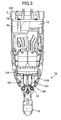
- Fig. 3 is a schematic side view partly cross-sectioned showing a combustion-type power tool as viewed from the left side in Fig. 1;
- Fig. 4 is a partial enlarged diagram showing the vicinity of the combustion chamber of the combustion-type power tool and shows a state where a sealed combustion chamber is provided in the fastener driving operation;
- Fig. 5 is a partial enlarged diagram showing the vicinity of a push switch of a combustion-type power tool according to a first embodiment of the present invention;
- Fig. 6A is a schematic diagram showing a switch protection member of the combustion-type power tool according to the first embodiment of the present invention;
- Fig. 6B is a cross-sectional view of the switch protection member taken along a line VIB-VIB in Fig. 6A;
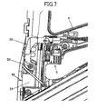
- Fig. 7 is a schematic diagram showing an internal arrangement of the canister accommodation portion prior to the assembly of the cover according to a first embodiment of the present invention;
- Fig. 8 is a schematic diagram showing a state an ignition arrangement in a combustion-type power tool according to a second embodiment of the present invention;
- Fig. 9 is a partial enlarged diagram showing the vicinity of a push switch of a combustion-type power tool according to a second embodiment of the present invention; and
- Fig. 10 is a schematic diagram showing a trigger switch of the combustion-type power tool according to a third embodiment of the present invention.
- A combustion-type power tool according to an embodiment of the invention will be described with reference to Figs. 1 through 7. The embodiment pertains to a combustion-type nail driver. In the following description, the terms "upper", "lower", "above", "below", "upward", "downward" and the like will be used assuming that the combustion-type nail driver is disposed in an orientation in which a nail is fired vertically downward.
- The combustion-
type nail driver 1 shown in Fig. 1 has ahousing 2 constituting an outer frame. Ahead cover 3 formed with anintake port 3a is mounted on the top of thehousing 2. Ahandle 4 extends from one side of thehousing 2. Thehandle 4 has detachably accommodates therein abattery pack 4a and a grip portion provided with atrigger switch 5 that commands a start of the nail driving. Thetrigger switch 5 includes amain switch section 5a, atrigger 36 to be manipulated by an operator, apin 37, aspring 38, and atrigger arm 39. Thepin 37 holds themain switch section 5a within an interior of thetrigger 36. Thespring 38 urges thetrigger 36 toward the lower side of the combustion-type nail driver 1. Thetrigger arm 39 is attached to the upper portion of thetrigger 36. - The
trigger 36 is in an inverted L shape and made from a plastic material as shown in Fig. 2A. An inside of thetrigger 36 has a triggerswitch accommodating portion 36a for accommodating therein themain switch section 5a, and aspring holding portion 36b as shown in Fig. 2B. Themain switch section 5a is a commodity type micro-switch, and is retained in thetrigger 36 by thepin 37 extending through ahole 36b formed at an end portion of thetrigger 36. Thespring 38 is also retained in thetrigger 36 by thespring holding portion 36C. On the other hand, thehandle 4 is formed with arecess 40 to which one end of thespring 38 is seated, so that thetrigger 36 is normally urged toward the lower side of the combustion-type nail driver 1. - The combustion-
type nail driver 1 also has acanister housing 29 at one side of thehousing 2 from which thehandle 4 extends. A gas canister 30 (see Fig. 4) containing therein a combustible liquidized gas is detachably installable in thecanister housing 29. Amagazine 6 accommodating therein a bundle of nails (not shown) is disposed below thehandle 4. - A
nose 7 extends from near the lower end of thehousing 2. Thenose 7 is integral with a cylinder 20 described later and has a tip end abuttable on aworkpiece 28. Thenose 7 is adapted for guiding sliding movement of adriver blade 23a described later and for guiding the nail driven into theworkpiece 28. Apush lever 9 is reciprocally slidingly movably supported to thenose 7, and projects from thetip end 7a of thenose 7. - As shown in Fig. 3, the
push lever 9 has an upper end in association with or abuttable on aconnection unit 12 fixed to a combustion-chamber frame 10 described later. Theconnection unit 12 includes a pair ofarm sections 12A each having stepwise bending portions, and aconnector section 12B having a generally rectangular shape. Each upper end of eacharm section 12A is bent into L-shape and fixed to the combustion-chamber frame 10. Each lower end of eacharm section 12A is fixed to theconnector section 12B by means ofscrews 12C. Theconnector section 12B has major sides each provided with an upstanding piece at each end portion of the major side. Each upstanding piece is formed with a thread hole with which eachscrew 12C is threadingly engageable. Each upstanding piece is bent at an angle of substantially 90 degrees at each major side, so that two bent upstanding pieces are in confronting relation to each other. Theconnector section 12B has a flat area beside the upstanding pieces. The flat area serves as a spring seat. - A
compression coil spring 22 is interposed between theconnector section 12B and the cylinder 20 for normally urging thepush lever 9 in a protruding direction from thehousing 2. When thehousing 2 is pressed toward aworkpiece 28 while thepush lever 9 is in abutment with the workpiece against a biasing force of thecompression coil spring 22, an upper portion of thepush lever 9 is retractable into thehousing 2. - A
cylinder head 11 is fixedly secured to the top of thehousing 2 and substantially covers the open top end of thehousing 2. Amotor 18 is disposed at one side of thecylinder head 11 opposite thecombustion chamber 26 as will be described later. An ignition plug (not shown) is disposed in the vicinity of themotor 18 and the ignition position is directed toward thecombustion chamber 26. - The
cylinder head 11 has a handle side in which is formed afuel ejection passage 25 which allows a combustible gas to pass therethrough. One end of theejection passage 25 opens at the lower surface of thecylinder head 11. Another end of theejection passage 25 serves as a gas canister connecting portion 25a in communication with agas canister 30. - The combustion-
chamber frame 10 is provided in thehousing 2 and is movable in the lengthwise direction of thehousing 2. The uppermost end of the combustion-chamber frame 10 is abuttable on the lower surface of thecylinder head 11. The combustion-chamber frame includes abase chamber frame 10a and achamber head 10b connected integrally using a bolt 10c (see Fig. 3). Since thearm section 12A is connected to the combustion-chamber frame 10, the combustion-chamber frame 10 is moved in accordance with the movement of thepush lever 9. A first plate 10D is fixed to an outer peripheral surface of the combustion-chamber frame 10. - The cylinder 20 is fixed to the
housing 2. An outer peripheral surface of the cylinder 20 is in sliding contact with the inner circumference of the combustion-chamber frame 10 for guiding the movement of the combustion-chamber frame 10. The cylinder 20 has an axially intermediate portion formed with anexhaust hole 21. An exhaust-gas check valve 21A is provided to selectively close theexhaust hole 21. - A
piston 23 is slidably and reciprocally movably provided in the cylinder 20. Thepiston 23 divides an inner space of the cylinder 20 into an upper space above thepiston 23 and a lower space below thepiston 23. Thedriver blade 23a extends downwards from the lower surface of thepiston 23 to thenose 7, so that the tip end of thedriver blade 23a can strike against the nail (not shown). Abumper 24 made from an elastic material such as rubber is disposed at a lower side of the cylinder 20. Thepiston 23 strikes against thebumper 24 when thepiston 23 is moved downward toward a bottom dead center. - When the upper end of the combustion-
chamber frame 10 abuts thecylinder head 11, thecylinder head 11, the combustion-chamber frame 10, and the upper cylinder space above thepiston 23 define a combustion chamber 26 (see Fig. 4). When the combustion-chamber frame 10 is separated from thecylinder head 11, a first flow passage 27A in communication with the atmosphere is provided between thecylinder head 11 and the upper end of the combustion-chamber frame 10, and asecond flow passage 27B in communication with the first flow passage 27A is provided between the inner peripheral surface of the combustion-chamber frame 10 and the outer peripheral surface of the cylinder 20. - The
housing 2 has a lower portion formed with an exhaust port 2a. The first andsecond flow passages 27A and 27B allow a combustion gas and a fresh air to pass along the outer peripheral surface of the cylinder 20 for discharging these gases through the exhaust port 2a of thehousing 2. Further, the above-describedintake port 3a is formed for supplying a fresh air into thecombustion chamber 26, and theexhaust hole 21 discharges combustion gas generated in thecombustion chamber 26. - The motor 13 has a fan shaft 18A, and a
fan 19 positioned in thecombustion chamber 23 is fixed to a tip end of the fan shaft 13A. Rotation of thefan 19 performs the following three functions. First, thefan 19 stirs and mixes the air with the combustible gas as long as the combustion-chamber frame 10 remains in abutment with thecylinder head 11. Second, after the mixed gas has been ignited, thefan 19 causes turbulence of the air-fuel mixture, thus promoting the turbulent combustion of the air-fuel mixture in thecombustion chamber 26. Third, thefan 19 performs scavenging such that the exhaust gas in thecombustion chamber 26 can be scavenged therefrom and also performs cooling of the cylinder 20 when the combustion-chamber frame 10 moves away from thecylinder head 11 and when the first andsecond flow passages 27A and 27B are provided. - A plurality of
ribs 10A protrudes radially inwardly from the portion of thecombustion chamber frame 10, the portion defining thecombustion chamber 26. Eachrib 10A extends in the axial direction of thecombustion chamber frame 10. Theribs 10A promote stirring and mixing of the air and the combustible gas in thecombustion chamber 26 in cooperation with thefan 18. - A
switch accommodating portion 31 is provided in the lower side of thecanister housing 29. Apush switch 32 is stored in theswitch accommodating portion 31. Thepush switch 32 is a commodity type micro-switch covered with aswitch protection member 33 made from an elastic material such as a rubber as shown in Figs. 5 and 6. Asecond plate 49 is provided to theswitch accommodating portion 31. A part of thesecond plate 49 is in contact with thepush switch 32. Thepush switch 32 can be turned ON when the first plate 10D fixed to the combustion-chamber frame 10 pushes up thesecond plate 49 as a result of elevating the combustion-chamber frame 10 by depressing of thepush lever 9 against the workpiece. Then, thepush switch 32 provides a command signal indicative of driving themotor 18. Thus, themotor 18 starts to rotate, thereby staring rotation of thefan 19. - As shown in Figs. 6A and 6B, the
switch protection member 33 haspawls 33A at an open insertion side of aswitch accommodation space 33b so as to prevent thepush switch 32 from being released from theaccommodation space 33b after the latter is set therein. - The
switch accommodation portion 31 of thehandle 4 has a wall whose surface is in conformance with the configuration of theswitch protection member 33. - As shown in Fig. 7, a
cover 34 is covered over theswitch accommodating portion 31, and is fixed to thehandle 4 by ascrew 50. Instead of thescrew 50, thecover 34 can also be fixed to thehandle 4 by a resilient locking engagement between the cover and a locking groove formed in thehandle 4. Fig. 8 shows an internal arrangement of thecanister accommodation portion 31 prior to the assembly of thecover 34, and Fig. 7 shows the state after assembly of thecover 34. An internalelectric wire 35 extends through thecanister accommodation portion 4a. - Next, operation of the combustion-
type power tool 1 will be described. In the non-operational state of the combustion-type nail driver 1, thepush lever 9 is biased downward by the biasing force of thecompression coil spring 22, so that thepush lever 9 protrudes from the lower end of thenose 7. Thus, the uppermost end of the combustion-chamber frame 10 is spaced away from thecylinder head 11 because the combustion-chamber frame 10 is in association with thepush lever 9 through thearm section 12A. Further, a part of the combustion-chamber frame 10 which part defines thecombustion chamber 26 is also spaced apart from the top portion of the cylinder 20. Hence, the first andsecond flow passages 27A and 27B are provided. In this condition, thepiston 23 stays at the top dead center in the cylinder 20. - With this state, if the
push lever 9 is pushed onto theworkpiece 28 while holding thehandle 4 by a user, thepush lever 9 is moved upward against the biasing force of thecompression coil spring 22. At the same time, the combustion-chamber frame 10 which is connected to thepush lever 9 through theconnection unit 12 is also moved upward, as shown in Fig. 3, closing the first flow passage 27A and hermetically sealing thecombustion chamber 26. - In accordance with the movement of the
push lever 9, thegas canister 30 is tilted toward thecylinder head 11. Thus, the injection rod 30a of thegas canister 30 is pressed against a gas canister connecting portion 25a of thecylinder head 11. Therefore, the liquidized combustible gas in thegas canister 30 is ejected once from the ejection port of thefuel ejection passage 25 into thecombustion chamber 26. - Further, in accordance with the movement of the
push lever 9, the first plate 10D fixed to the combustion-chamber frame 10 pushes up thesecond plate 49 whereupon theswitch 32 is turned ON to supply electric power to themotor 18 and start rotation of thefan 19. Rotation of thefan 19 in thecombustion chamber 26 in which a hermetically sealed space is provided, stirs and mixes the ejected combustible gas with air in thecombustion chamber 26. - In this state, when the
trigger switch 5 provided at thehandle 4 is turned ON, spark is generated at theignition plug 50 to ignite the combustible gas. As a result of combustion, volumetric expansion of the combustion gas occurs within thecombustion chamber 26 to move thepiston 23 downwardly. Accordingly, thedriver blade 23a drives the nail held in thenose 7 into theworkpiece 28 until thepiston 23 strikes against thebumper 24. - After the nail driving, the
piston 23 strikes against thebumper 24, and the combustion gas is discharged out of the cylinder 20 through theexhaust hole 21 of the cylinder 20. When the inner space of the cylinder 20 and thecombustion chamber 26 becomes the atmospheric pressure, the exhaust-gas check valve 21A is closed. Combustion gas still remaining in the cylinder 20 and thecombustion chamber 26 has a high temperature at a phase immediately after the combustion. The heat is absorbed through the inner surfaces of the cylinder 20 and the combustion-chamber frame 10, and the temperature of these components is also increased. However, the absorbed heat is released to the atmosphere through the outer surfaces of the cylinder 20 and the combustion-chamber frame 10. - Combustion heat of the combustion gas is absorbed into such components as the cylinder 20, so that the combustion gas is abruptly cooled down and a volume of the combustion gas is decreased. Thus, the pressure in the sealed space in the cylinder 20 above the
piston 23 further drops to less than the atmospheric pressure, creating a so-called "thermal vacuum". Accordingly, thepiston 23 is moved back to the initial top dead center position. - Thereafter, the
trigger switch 5 is turned OFF, and the user lifts thenail driver 1 until thepush lever 9 is separated from theworkpiece 28. As a result, thepush lever 9 and the combustion-chamber frame 10 move downward due to the biasing force of thecompression coil spring 22. In this case, thefan 19 keeps rotating for a predetermined period of time in spite of OFF state of thetrigger switch 5 because of an operation of a control portion (not shown). In the state shown in Fig. 1, the first and second flow passages are provided at the upper side of the combustion-chamber frame 10, so that fresh air flows into thecombustion chamber 26 through theintake port 3a formed in thehead cover 3 and the residual gas is expelled through the exhaust port 2a by the rotation of thefan 19. Thus, thecombustion chamber 26 is scavenged. Then, the rotation of thefan 19 is stopped to restore an initial stationary state. Thereafter, subsequent nail driving operation can be performed by repeating the above described operation process. - As described above, since the
main switch section 5a of thetrigger switch 5 is attached to thehandle 4 through the resilient member such as thespring 38, transmission of the impact force at the time of faster driving operation to themain switch section 5a can be moderated by thespring 38. Since theswitch protection member 33 haspawls 33A, thepush switch 32 can be positioned stably inswitch protection member 33. Further, thecover 34 can prevent theswitch protection member 31 from being disassembled from thehandle 4 after theswitch protection member 33 protecting thepush switch 32 is installed in thehandle 4. Thecover 34 also serves to cover and protect thewire 35. - Since, the
push switch 32 is covered with theswitch protection member 33, transmission of the impact force about 10 times as large as the tolerance against impact at the time of faster driving operation to thepush switch 32 can be moderated by theswitch protection member 33. Accordingly, this construction prevents thepush switch 32 from break down by the impact force damaging to the mechanical junction of thepush switch 32 and the impact force causing chattering to cause frictional wearing in the junction. Since it is not necessary to use a photoelectric switch for reducing the mechanical junction of the combustion-type nail driver 1, production cost of the combustion-type nail driver 1 can be reduced. - A combustion type power tool according to a second embodiment of the present invention will be described with reference to Fig. 9. The second embodiment pertains to a protective arrangement for a
push switch 32. In the first embodiment, theswitch protection member 33 is an integral piece for covering almost all outer surface of thepush switch 32. On the other hand, in the second embodiment, aswitch protection member 133 is segmented into a plurality ofsegments push switch 32. The reason is as follows. - Impact force imparted on the tool body depends on the condition of using the tool. However, generally, the largest impact is applied when the
piston 23 strikes against thebumper 24, and the second largest impact is applied when the combustible gas is ignited and exploded. A force directing upward, i.e., directing to thehead cover 3 is applied to thepush switch 32 when thepiston 23 strikes thebumper 24, and a force directing downward, i.e., directing to thenose 7 is applied to thepush switch 32 at the time of ignition and explosion. Therefore, the switch protecting member must at least includes theupper segment 133A in order to protect thepush switch 32 against the large impact force. This protection can be improved by providing thelower segment 133B. Further, the left segment 133Cc and theright segment 133D can prevent thepush switch 30 from is accidental displacement due to impact. - Fig. 10 shows an arrangement for protecting a
main switch section 5a of the trigger switch in a combustion type power tool according to a third embodiment of the present invention. In the third embodiment, themain switch section 5a is attached to thetrigger 36 through a mainswitch protection member 100 made from an elastic material such as a rubber. The mainswitch protection member 100 is positioned to surround themain switch section 5a. With this arrangement an impact force applied to thetrigger switch 5 can further be reduced to prolong service life thereof. As a modification, a segmented protection member can be provided only at an upper face and a lower face of themain switch section 5a, i.e., at the position to cross the reciprocating direction of thepiston 23.
Claims (9)
- A combustion-type power tool comprising:a housing having one end and another end;a handle provided on the housing;a cylinder head disposed at the one end of the housing;a cylinder disposed in and fixed to the housing, the cylinder defining an axial direction, the cylinder having one end positioned at the one end side of the housing and another end positioned at the another end side of the housing;a piston slidably disposed in the cylinder and reciprocally movable in the axial direction;a combustion chamber frame disposed in the housing and movable in the axial direction, the combustion chamber frame being abuttable on the cylinder head to provide a combustion chamber in cooperation with the cylinder head and the piston;an elastic member provided on one of the housing and the handle; anda switch provided on one of the housing and the handle through the elastic member, the switch having one end portion facing to the one end side of the housing, the elastic member covering the one end portion.
- The combustion-type power tool according to claim 1,
wherein the switch has another end portion facing to the another end side of the housing,
wherein the elastic member comprises a pair of elastic segments, the one of the elastic segments covering the one end portion and the other of the elastic segment covering the another end portion. - The combustion-type power tool according to claim 1, further comprising a nose provided on the another end of the cylinder, the nose extending in a protruding direction away from the cylinder;
a push lever disposed at the another end of the housing and movable along the nose in the axial direction upon pressing against a workpiece;
a connecting unit connecting the combustion chamber frame with the push lever; and
a motor disposed at the cylinder head. - The combustion-type power tool according to claim 3,
wherein the switch detects a predetermined position of the combustion chamber frame when the push lever is pressed against a workpiece, the switch providing a command signal indicative of driving the motor. - A combustion-type power tool comprising:a housing having one end and another end;a cylinder head disposed at the one end of the housing;a cylinder disposed in and fixed to the housing, the cylinder defining an axial direction, the cylinder having one end positioned at the one end side of the housing and another end positioned at the another end side of the housing;a piston slidably disposed in the cylinder and reciprocally movable in the axial direction;a combustion chamber frame disposed in the housing and movable in the axial direction, the combustion chamber frame being abuttable on the cylinder head to provide a combustion chamber in cooperation with the cylinder head and the piston;an resilient member attached to the handle; anda trigger provided on the handle through the resilient member.
- The combustion-type power tool according to claim 5, further comprising an elastic member provided on the trigger; and
a main switch provided on the trigger through the elastic member, the main switch having one end portion facing to the one end side of the housing, the elastic member covering the one end portion. - The combustion-type power tool according to claim 6,
wherein the main switch having another end portion facing to the another end side of the housing,
wherein the elastic member comprises a pair of elastic segments, the one of the elastic segments covering the one end portion and the other of the elastic segment covering the another end portion. - The combustion-type power tool according to claim 5, further comprising a handle provided on the housing;
a nose provided on the another end of the cylinder, the nose extending in a protruding direction away from the cylinder;
a push lever disposed at the another end of the housing and movable along the nose in the axial direction upon pressing against a workpiece;
a connecting unit connecting the combustion chamber frame with the push lever; and
an ignition plug exposed to the combustion chamber, the ignition plug igniting a mixture of air and the fuel in the combustion chamber;
wherein the cylinder head is formed with a fuel injection passage through which the fuel is flowed. - The combustion-type power tool according to claim 8,
wherein the main switch provides a command signal indicative of generating a spark to the ignition plug for igniting a mixture of air and the fuel.
Applications Claiming Priority (2)
| Application Number | Priority Date | Filing Date | Title |
|---|---|---|---|
| JP2005043278 | 2005-02-18 | ||
| JP2006014463A JP2006255880A (en) | 2005-02-18 | 2006-01-23 | Combustion-type power tool |
Publications (3)
| Publication Number | Publication Date |
|---|---|
| EP1693156A2 true EP1693156A2 (en) | 2006-08-23 |
| EP1693156A3 EP1693156A3 (en) | 2010-01-20 |
| EP1693156B1 EP1693156B1 (en) | 2012-10-03 |
Family
ID=36405939
Family Applications (1)
| Application Number | Title | Priority Date | Filing Date |
|---|---|---|---|
| EP06250876A Expired - Lifetime EP1693156B1 (en) | 2005-02-18 | 2006-02-18 | Combustion-type power tool having switch protection arrangement |
Country Status (3)
| Country | Link |
|---|---|
| US (1) | US7484481B2 (en) |
| EP (1) | EP1693156B1 (en) |
| JP (1) | JP2006255880A (en) |
Cited By (2)
| Publication number | Priority date | Publication date | Assignee | Title |
|---|---|---|---|---|
| WO2008029901A1 (en) * | 2006-09-05 | 2008-03-13 | Hitachi Koki Co., Ltd. | Combustion-type power tool |
| EP2301720A3 (en) * | 2009-09-25 | 2011-07-13 | Panasonic Electric Works Power Tools Co., Ltd. | Electric power tool |
Families Citing this family (10)
| Publication number | Priority date | Publication date | Assignee | Title |
|---|---|---|---|---|
| DE102004047279A1 (en) * | 2004-09-29 | 2006-04-06 | Hilti Ag | Internal combustion setting device |
| US7931181B2 (en) * | 2005-02-18 | 2011-04-26 | Hitachi Koki Co., Ltd. | Combustion-type power tool with trigger control arrangements |
| JP5070876B2 (en) * | 2007-02-15 | 2012-11-14 | マックス株式会社 | Gas fired driving tool |
| JP2008221436A (en) * | 2007-03-15 | 2008-09-25 | Hitachi Koki Co Ltd | Combustion power tool |
| JP4945359B2 (en) | 2007-07-26 | 2012-06-06 | 株式会社マキタ | Combustion type driving tool |
| JP2010224640A (en) * | 2009-03-19 | 2010-10-07 | Toshiba Tec Corp | Handy leader |
| US9662777B2 (en) | 2013-08-22 | 2017-05-30 | Techtronic Power Tools Technology Limited | Pneumatic fastener driver |
| JP6984681B2 (en) * | 2016-07-15 | 2021-12-22 | マックス株式会社 | Driving tool |
| JP6687095B2 (en) * | 2018-12-07 | 2020-04-22 | マックス株式会社 | Driving tool |
| JP7798659B2 (en) * | 2022-04-08 | 2026-01-14 | 株式会社マキタ | Driving tools |
Citations (5)
| Publication number | Priority date | Publication date | Assignee | Title |
|---|---|---|---|---|
| US4403722A (en) | 1981-01-22 | 1983-09-13 | Signode Corporation | Combustion gas powered fastener driving tool |
| US4483473A (en) | 1983-05-02 | 1984-11-20 | Signode Corporation | Portable gas-powered fastener driving tool |
| US4483474A (en) | 1981-01-22 | 1984-11-20 | Signode Corporation | Combustion gas-powered fastener driving tool |
| US4522162A (en) | 1981-01-22 | 1985-06-11 | Signode Corporation | Portable gas-powered tool with linear motor |
| US5191209A (en) | 1991-06-17 | 1993-03-02 | Illinois Tool Works Inc. | Photoelectric switch sealed against infiltration of contaminants |
Family Cites Families (31)
| Publication number | Priority date | Publication date | Assignee | Title |
|---|---|---|---|---|
| US3215807A (en) * | 1961-11-01 | 1965-11-02 | Master Cons Inc | Floating mount for circuit breakers |
| US3322924A (en) * | 1965-03-04 | 1967-05-30 | Black & Decker Mfg Co | Translatory mechanical member with molded hinge portion for use in electric switchesand other applications |
| US3720188A (en) * | 1971-01-11 | 1973-03-13 | G Mead | Compact steam generator and system |
| DE3216446A1 (en) * | 1982-05-03 | 1983-11-03 | Fa. Andreas Stihl, 7050 Waiblingen | SAFETY DEVICE ON A PORTABLE, MOTOR-DRIVEN HAND DEVICE |
| US4613327A (en) * | 1984-01-26 | 1986-09-23 | Tegrarian Haig V | Apparatus for infusing blood and other related fluids into a patient's body |
| JPS649149U (en) | 1987-04-06 | 1989-01-18 | ||
| JPS6434753U (en) | 1987-08-26 | 1989-03-02 | ||
| US4981120A (en) * | 1989-05-08 | 1991-01-01 | Mangum Jr Travis | Low profile internal combustion engine, and lawnmower comprising same |
| JPH0325307A (en) | 1989-06-22 | 1991-02-04 | Fuji Electric Co Ltd | External light triangular system distance measuring instrument |
| JPH0411337A (en) | 1990-04-27 | 1992-01-16 | Sharp Corp | Optical disk |
| JP2843117B2 (en) | 1990-06-15 | 1999-01-06 | 松下電工株式会社 | Incandescent lighting device |
| US5615696A (en) * | 1992-07-24 | 1997-04-01 | Lawler; Oliver W. | Apparatus for treating pipe |
| JP3261263B2 (en) * | 1994-07-12 | 2002-02-25 | 本田技研工業株式会社 | Power unit for saddle type vehicles |
| US6082468A (en) * | 1998-04-20 | 2000-07-04 | Snap-On Tools Company | Interchangeable grips for power hand tools |
| CA2276648A1 (en) * | 1999-06-23 | 2000-12-23 | Bombardier Inc. | Improved all terrain vehicle |
| US6547021B1 (en) * | 2000-11-22 | 2003-04-15 | Yamaha Hatsudoki Kabushiki Kaisha | Decompression arrangement for land vehicle |
| US7225959B2 (en) * | 2001-04-30 | 2007-06-05 | Black & Decker, Inc. | Portable, battery-powered air compressor for a pneumatic tool system |
| CN1273270C (en) * | 2002-08-09 | 2006-09-06 | 日立工机株式会社 | Nailing gun using gas as power |
| US7040520B2 (en) * | 2002-09-12 | 2006-05-09 | Illinois Tool Works Inc. | Fan motor suspension mount for a combustion-powered tool |
| DE10244250A1 (en) * | 2002-09-24 | 2004-03-25 | Hilti Ag | Fuel-operated fastening gun, firing e.g. studs into concrete, includes metering unit delivering pre-adjusted, constant volume of fuel |
| DE10259773A1 (en) * | 2002-12-19 | 2004-07-01 | Hilti Ag | Internal combustion engine-operated tool and method for cooling its combustion chamber |
| DE10259817B4 (en) * | 2002-12-19 | 2015-03-05 | Hilti Aktiengesellschaft | Internal combustion fastener for fasteners |
| JP4145139B2 (en) * | 2002-12-26 | 2008-09-03 | 本田技研工業株式会社 | Arrangement structure of gear position detection device of transmission |
| EP1459850B1 (en) * | 2003-03-19 | 2008-05-21 | Hitachi Koki Co., Ltd. | Combustion type power tool having avoiding unit for avoiding overheating to mechanical components in the tool |
| DE10319647B3 (en) * | 2003-05-02 | 2004-09-02 | Hilti Ag | Setting device for attachment elements, e.g. nails, bolts or pins, has reader of attachment element magazine strip coding, controller for adjusting setting parameters depending on coding data |
| JP4144472B2 (en) * | 2003-08-11 | 2008-09-03 | 日立工機株式会社 | Combustion power tool |
| EP1529601B1 (en) * | 2003-11-07 | 2007-10-31 | Makita Corporation | Combustion power tool |
| JP4608974B2 (en) * | 2004-07-09 | 2011-01-12 | 日立工機株式会社 | Combustion nailer |
| US7143920B2 (en) * | 2004-09-01 | 2006-12-05 | Illinois Tool Works Inc. | Primary and secondary handles for power tool |
| US7107944B1 (en) * | 2005-05-05 | 2006-09-19 | Illinois Tool Works, Inc. | Beam system membrane suspension for a motor mount |
| US7299963B2 (en) * | 2005-05-23 | 2007-11-27 | Illinois Tool Works Inc. | Temperature sensor for combustion nailer |
-
2006
- 2006-01-23 JP JP2006014463A patent/JP2006255880A/en not_active Withdrawn
- 2006-02-17 US US11/356,208 patent/US7484481B2/en not_active Expired - Lifetime
- 2006-02-18 EP EP06250876A patent/EP1693156B1/en not_active Expired - Lifetime
Patent Citations (6)
| Publication number | Priority date | Publication date | Assignee | Title |
|---|---|---|---|---|
| US4403722A (en) | 1981-01-22 | 1983-09-13 | Signode Corporation | Combustion gas powered fastener driving tool |
| US4483474A (en) | 1981-01-22 | 1984-11-20 | Signode Corporation | Combustion gas-powered fastener driving tool |
| US4522162A (en) | 1981-01-22 | 1985-06-11 | Signode Corporation | Portable gas-powered tool with linear motor |
| US4522162B1 (en) | 1981-01-22 | 1989-03-21 | ||
| US4483473A (en) | 1983-05-02 | 1984-11-20 | Signode Corporation | Portable gas-powered fastener driving tool |
| US5191209A (en) | 1991-06-17 | 1993-03-02 | Illinois Tool Works Inc. | Photoelectric switch sealed against infiltration of contaminants |
Cited By (4)
| Publication number | Priority date | Publication date | Assignee | Title |
|---|---|---|---|---|
| WO2008029901A1 (en) * | 2006-09-05 | 2008-03-13 | Hitachi Koki Co., Ltd. | Combustion-type power tool |
| AU2007292056B2 (en) * | 2006-09-05 | 2010-12-02 | Hitachi Koki Co., Ltd. | Combustion-type power tool |
| CN101511546B (en) * | 2006-09-05 | 2012-05-30 | 日立工机株式会社 | Combustion Power Tools |
| EP2301720A3 (en) * | 2009-09-25 | 2011-07-13 | Panasonic Electric Works Power Tools Co., Ltd. | Electric power tool |
Also Published As
| Publication number | Publication date |
|---|---|
| US7484481B2 (en) | 2009-02-03 |
| JP2006255880A (en) | 2006-09-28 |
| EP1693156A3 (en) | 2010-01-20 |
| EP1693156B1 (en) | 2012-10-03 |
| US20060185630A1 (en) | 2006-08-24 |
Similar Documents
| Publication | Publication Date | Title |
|---|---|---|
| EP2061631B1 (en) | Combustion-type power tool | |
| EP1588804B1 (en) | Combustion-type power tool | |
| US7194988B2 (en) | Combustion-type power tool | |
| US7387092B2 (en) | Combustion-type power tool having cooling arrangement | |
| EP1693156B1 (en) | Combustion-type power tool having switch protection arrangement | |
| EP1391270B1 (en) | Combustion-powered nail gun | |
| US20070138231A1 (en) | Combustion type power tool having segmental connection unit | |
| JP5429512B2 (en) | Driving machine | |
| US7931181B2 (en) | Combustion-type power tool with trigger control arrangements | |
| EP1693158A2 (en) | Combustion-type power tool having ignition proof arrangement | |
| EP1693157B1 (en) | Combustion-type power tool having ignition proof arrangement | |
| US7131404B2 (en) | Combustion-type power tool having gas canister cooling arrangement |
Legal Events
| Date | Code | Title | Description |
|---|---|---|---|
| PUAI | Public reference made under article 153(3) epc to a published international application that has entered the european phase |
Free format text: ORIGINAL CODE: 0009012 |
|
| AK | Designated contracting states |
Kind code of ref document: A2 Designated state(s): AT BE BG CH CY CZ DE DK EE ES FI FR GB GR HU IE IS IT LI LT LU LV MC NL PL PT RO SE SI SK TR |
|
| AX | Request for extension of the european patent |
Extension state: AL BA HR MK YU |
|
| RIC1 | Information provided on ipc code assigned before grant |
Ipc: B25C 1/08 20060101AFI20060530BHEP Ipc: B25F 5/00 20060101ALI20090828BHEP Ipc: H01H 9/06 20060101ALI20090828BHEP |
|
| 17P | Request for examination filed |
Effective date: 20090903 |
|
| PUAL | Search report despatched |
Free format text: ORIGINAL CODE: 0009013 |
|
| AK | Designated contracting states |
Kind code of ref document: A3 Designated state(s): AT BE BG CH CY CZ DE DK EE ES FI FR GB GR HU IE IS IT LI LT LU LV MC NL PL PT RO SE SI SK TR |
|
| AX | Request for extension of the european patent |
Extension state: AL BA HR MK YU |
|
| 17Q | First examination report despatched |
Effective date: 20100810 |
|
| AKX | Designation fees paid |
Designated state(s): DE FR GB |
|
| REG | Reference to a national code |
Ref country code: DE Ref legal event code: R079 Ref document number: 602006032229 Country of ref document: DE Free format text: PREVIOUS MAIN CLASS: B25C0001080000 Ipc: H01H0003600000 |
|
| GRAP | Despatch of communication of intention to grant a patent |
Free format text: ORIGINAL CODE: EPIDOSNIGR1 |
|
| RIC1 | Information provided on ipc code assigned before grant |
Ipc: B25C 1/08 20060101ALI20120323BHEP Ipc: H01H 9/06 20060101ALI20120323BHEP Ipc: B25F 5/00 20060101ALI20120323BHEP Ipc: H01H 13/08 20060101ALI20120323BHEP Ipc: H01H 3/60 20060101AFI20120323BHEP |
|
| GRAS | Grant fee paid |
Free format text: ORIGINAL CODE: EPIDOSNIGR3 |
|
| GRAA | (expected) grant |
Free format text: ORIGINAL CODE: 0009210 |
|
| AK | Designated contracting states |
Kind code of ref document: B1 Designated state(s): DE FR GB |
|
| REG | Reference to a national code |
Ref country code: GB Ref legal event code: FG4D |
|
| REG | Reference to a national code |
Ref country code: DE Ref legal event code: R081 Ref document number: 602006032229 Country of ref document: DE Owner name: KOKI HOLDINGS CO., LTD., JP Free format text: FORMER OWNER: HITACHI KOKI CO., LTD., TOKIO/TOKYO, JP |
|
| REG | Reference to a national code |
Ref country code: DE Ref legal event code: R096 Ref document number: 602006032229 Country of ref document: DE Effective date: 20121129 |
|
| PLBE | No opposition filed within time limit |
Free format text: ORIGINAL CODE: 0009261 |
|
| STAA | Information on the status of an ep patent application or granted ep patent |
Free format text: STATUS: NO OPPOSITION FILED WITHIN TIME LIMIT |
|
| 26N | No opposition filed |
Effective date: 20130704 |
|
| REG | Reference to a national code |
Ref country code: DE Ref legal event code: R097 Ref document number: 602006032229 Country of ref document: DE Effective date: 20130704 |
|
| REG | Reference to a national code |
Ref country code: FR Ref legal event code: PLFP Year of fee payment: 11 |
|
| REG | Reference to a national code |
Ref country code: FR Ref legal event code: PLFP Year of fee payment: 12 |
|
| REG | Reference to a national code |
Ref country code: DE Ref legal event code: R082 Ref document number: 602006032229 Country of ref document: DE Representative=s name: KLUNKER IP PATENTANWAELTE PARTG MBB, DE |
|
| REG | Reference to a national code |
Ref country code: FR Ref legal event code: PLFP Year of fee payment: 13 |
|
| REG | Reference to a national code |
Ref country code: DE Ref legal event code: R082 Ref document number: 602006032229 Country of ref document: DE Representative=s name: KLUNKER IP PATENTANWAELTE PARTG MBB, DE Ref country code: DE Ref legal event code: R081 Ref document number: 602006032229 Country of ref document: DE Owner name: KOKI HOLDINGS CO., LTD., JP Free format text: FORMER OWNER: HITACHI KOKI CO., LTD., TOKIO/TOKYO, JP |
|
| REG | Reference to a national code |
Ref country code: DE Ref legal event code: R084 Ref document number: 602006032229 Country of ref document: DE |
|
| REG | Reference to a national code |
Ref country code: GB Ref legal event code: 746 Effective date: 20181031 |
|
| PGFP | Annual fee paid to national office [announced via postgrant information from national office to epo] |
Ref country code: FR Payment date: 20230220 Year of fee payment: 18 |
|
| PGFP | Annual fee paid to national office [announced via postgrant information from national office to epo] |
Ref country code: GB Payment date: 20230221 Year of fee payment: 18 |
|
| GBPC | Gb: european patent ceased through non-payment of renewal fee |
Effective date: 20240218 |
|
| PG25 | Lapsed in a contracting state [announced via postgrant information from national office to epo] |
Ref country code: GB Free format text: LAPSE BECAUSE OF NON-PAYMENT OF DUE FEES Effective date: 20240218 |
|
| PG25 | Lapsed in a contracting state [announced via postgrant information from national office to epo] |
Ref country code: FR Free format text: LAPSE BECAUSE OF NON-PAYMENT OF DUE FEES Effective date: 20240229 |
|
| PG25 | Lapsed in a contracting state [announced via postgrant information from national office to epo] |
Ref country code: GB Free format text: LAPSE BECAUSE OF NON-PAYMENT OF DUE FEES Effective date: 20240218 Ref country code: FR Free format text: LAPSE BECAUSE OF NON-PAYMENT OF DUE FEES Effective date: 20240229 |
|
| PGFP | Annual fee paid to national office [announced via postgrant information from national office to epo] |
Ref country code: DE Payment date: 20250218 Year of fee payment: 20 |
|
| REG | Reference to a national code |
Ref country code: DE Ref legal event code: R071 Ref document number: 602006032229 Country of ref document: DE |