EP1693143A1 - Weld metal of low temperature toughness and SR cracking resistance used for high-strength Cr-Mo steel - Google Patents
Weld metal of low temperature toughness and SR cracking resistance used for high-strength Cr-Mo steel Download PDFInfo
- Publication number
- EP1693143A1 EP1693143A1 EP06002363A EP06002363A EP1693143A1 EP 1693143 A1 EP1693143 A1 EP 1693143A1 EP 06002363 A EP06002363 A EP 06002363A EP 06002363 A EP06002363 A EP 06002363A EP 1693143 A1 EP1693143 A1 EP 1693143A1
- Authority
- EP
- European Patent Office
- Prior art keywords
- weld metal
- content
- strength
- toughness
- steel
- Prior art date
- Legal status (The legal status is an assumption and is not a legal conclusion. Google has not performed a legal analysis and makes no representation as to the accuracy of the status listed.)
- Granted
Links
Images

Classifications
-
- B—PERFORMING OPERATIONS; TRANSPORTING
- B23—MACHINE TOOLS; METAL-WORKING NOT OTHERWISE PROVIDED FOR
- B23K—SOLDERING OR UNSOLDERING; WELDING; CLADDING OR PLATING BY SOLDERING OR WELDING; CUTTING BY APPLYING HEAT LOCALLY, e.g. FLAME CUTTING; WORKING BY LASER BEAM
- B23K35/00—Rods, electrodes, materials, or media, for use in soldering, welding, or cutting
- B23K35/22—Rods, electrodes, materials, or media, for use in soldering, welding, or cutting characterised by the composition or nature of the material
- B23K35/24—Selection of soldering or welding materials proper
- B23K35/30—Selection of soldering or welding materials proper with the principal constituent melting at less than 1550°C
- B23K35/3053—Fe as the principal constituent
- B23K35/308—Fe as the principal constituent with Cr as next major constituent
-
- G—PHYSICS
- G06—COMPUTING OR CALCULATING; COUNTING
- G06F—ELECTRIC DIGITAL DATA PROCESSING
- G06F1/00—Details not covered by groups G06F3/00 - G06F13/00 and G06F21/00
- G06F1/26—Power supply means, e.g. regulation thereof
- G06F1/28—Supervision thereof, e.g. detecting power-supply failure by out of limits supervision
-
- B—PERFORMING OPERATIONS; TRANSPORTING
- B23—MACHINE TOOLS; METAL-WORKING NOT OTHERWISE PROVIDED FOR
- B23K—SOLDERING OR UNSOLDERING; WELDING; CLADDING OR PLATING BY SOLDERING OR WELDING; CUTTING BY APPLYING HEAT LOCALLY, e.g. FLAME CUTTING; WORKING BY LASER BEAM
- B23K35/00—Rods, electrodes, materials, or media, for use in soldering, welding, or cutting
- B23K35/22—Rods, electrodes, materials, or media, for use in soldering, welding, or cutting characterised by the composition or nature of the material
- B23K35/36—Selection of non-metallic compositions, e.g. coatings or fluxes; Selection of soldering or welding materials, conjoint with selection of non-metallic compositions, both selections being of interest
- B23K35/3601—Selection of non-metallic compositions, e.g. coatings or fluxes; Selection of soldering or welding materials, conjoint with selection of non-metallic compositions, both selections being of interest with inorganic compounds as principal constituents
- B23K35/3602—Carbonates, basic oxides or hydroxides
-
- C—CHEMISTRY; METALLURGY
- C21—METALLURGY OF IRON
- C21D—MODIFYING THE PHYSICAL STRUCTURE OF FERROUS METALS; GENERAL DEVICES FOR HEAT TREATMENT OF FERROUS OR NON-FERROUS METALS OR ALLOYS; MAKING METAL MALLEABLE, e.g. BY DECARBURISATION OR TEMPERING
- C21D1/00—General methods or devices for heat treatment, e.g. annealing, hardening, quenching or tempering
- C21D1/26—Methods of annealing
- C21D1/30—Stress-relieving
-
- G—PHYSICS
- G06—COMPUTING OR CALCULATING; COUNTING
- G06F—ELECTRIC DIGITAL DATA PROCESSING
- G06F11/00—Error detection; Error correction; Monitoring
- G06F11/30—Monitoring
- G06F11/34—Recording or statistical evaluation of computer activity, e.g. of down time, of input/output operation ; Recording or statistical evaluation of user activity, e.g. usability assessment
- G06F11/3438—Recording or statistical evaluation of computer activity, e.g. of down time, of input/output operation ; Recording or statistical evaluation of user activity, e.g. usability assessment monitoring of user actions
Definitions
- the present invention relates to a weld metal to be used for welding a high -strength steel material such as Cr - Mo - V steel (Cr: 2.0 to 3.25 mass% (referred to as %, hereinafter), Mo: 0.9 to 1.2%, V: 0.2 to 0.35%). More particularly, itpertains to technology for forming by arc welding method, a weld metal applicable to a steel material which is employed in cold districts and is required to have low temperature toughness.
- Cr -Mo steel which contains Cr and/or Mo and is excellent in requisite characteristics such as heat resistance and pressure tightness taking into consideration the working environment of a high temperature and high pressure.
- Cr -Mo steel is also required to be excellent in high temperature strength (particularly, high temperature creep strength ) along with toughness.
- a weld metal to be formed is required to be superior to previous ones in terms of strength at room temperature and elevated temperatures, toughness, creep strength, tempering brittleness resistance characteristic (to be lessened in brittleness in use in a high temperature environment) and SR cracking resistance (to be less liable to cause intergranular cracking due to precipitation aging).
- weld structures made of Cr - Mo - V steel have created a serious problem of intergranular cracking due to precipitation aging so - called SR cracking.
- the Cr - Mo - V steel be excellent in such characteristics (SR cracking resistance).
- Patent Literature 1 discloses that the toughness of the weld metal is enhanced through decreased oxygen content by bringing Si content in the weld metal up to at least 0. 10%.
- Patent Literature 2 discloses that increased oxygen content in weld metal for high - strength Cr - Mo - steel increases intergranular surfaces by the precipitation of dense texture along grain boundaries, and thus enables the formation of a weld metal superior to a weld metal having lower oxygen content in terms of SR cracking resistance.
- This technology improves SR cracking resistance by bringing the oxygen content to 0. 030 to 0.060%, and compensates for toughness lowering by optimizing the contents of carbon and Mn in the weld metal.
- oxygen shows conflicting behavior in regard to toughness and SR cracking resistance, and therefore the control of oxygen content alone makes it difficult to reconcile both toughness and SR cracking resistance, whereby it follows that either of the characteristic deteriorates.
- the object of the present invention that has been made under such circumstances is to provide a weld metal which is used for high - strength Cr - Mo - steel and which is improved in toughness (particularly low temperature toughness) and SR cracking resistance as well, while maintaining its high - temperature strength.
- the gist and summary of the weld metal having enabled to solve the above - mentioned theme reside in a weld metal which is formed by an arc welding method and which comprises 0.02 to 0.10% of C (% by mass ; the same holds also hereinafter), 0.05 to 0.4% of Si, 0.3 to 1.2% of Mn, 0.8 to 3.25% of Cr, at most 2% (inclusive of 0% ) of Mo , 0.30 to 1.0% of V, at most 0.03% of N, while suppressing the contents of Al, Ti and Ni to at most 0.03%, at most 0.03% and at most 0.40% respectively, wherein the sum total ( [Mn] + [Ni] ) of Mn content [Mn] and Ni content [Ni] is at most 1.2%, the balance is Fe and inevitable impurities, the contents of P, S, Sn, As and Sb among the inevitable impurities are suppressed each to atmost 0.01%, the content of O is suppressed to at most 0.040%, EV value as defined by
- the above - mentioned equivalent circle diameter is determined by a diameter of a circle the area of which is assumed to be equal to that of precipitate, paying attention to the size of the precipitate. It is also the circle diameter that is recognized by means of replica method on an observation surface with a transmission type electron microscope.
- M 3 C cementites
- C carbon
- MX in formula "MX” represents alloying metal elements such as V, Nb, Ti and/or Mo.
- X in formula "MX” represents C and/or N.
- MX means the carbide, nitride or carbonitride having a crystal structure of sodium chloride structure.
- C which exerts a great influence on quenching hardenability, is an important element for assuring toughness and strengths at room temperature and elevated temperature.
- the content of C in the weld metal when being less than 0. 02%, results in lowered strength, etc., whereas the content thereof, when being more than 0.10%, brings about excessively high strength, thus markedly lowers the toughness.
- the content of C therein needs to be in the range of 0.02 to 0.10%. From the aspect of improving the characteristic, the lower and upper limits of the contents thereof are preferably 0.04% and 0.08%, respectively.
- Si which has deoxidizing effect, exhibits an effect on controlling the amount of oxygen in the weld metal.
- the content of Si needs to be at least 0.05%, but when exceeding 0.4% being excessively high, causes deterioration in tempering brittleness characteristics and SR cracking resistance, and besides brings about excessively high strength, thus contributing to lowered toughness.
- the lower and upper limits of the contents thereof are preferably 0.10% and 0.30%, respectively.
- Mn exerts effects on enhancing high temperature strength and toughness of the weld metal, and has a function of controlling oxygen amount in the weld metal by deoxidizing action.
- the content of Mn needs to be at least 0.3%, but when exceeding 1.2% being excessively high, causes deterioration in creep strength, tempering brittleness resistance characteristic and SR cracking resistance.
- the content of Mn in the weld metal needs to be 0.3 to 1.2%, and the lower and upper limits of the contents thereof are preferably 0.5% and 1.0%, respectively.
- Cr and Mo are each a fundamental component for high - strength 2.25 to 3% Cr - 1% Mo steel.
- the content of Cr in the weld metal is less than 0.8% or more than 3.25%, or the content of Mo in the weld metal is more than 2.0%, the working effects of the present invention are recognized.
- the above -mentioned scope of the base - material components is not practically employed in a high temperature environment as an object. Therefore the content of Cr is set on 0.8 to 3.25%, and that of Mo on at most 2.0%.
- the lower and upper limits of the content of Cr are preferably 2.0% and 3.0%, respectively, while the upper limit of the content of Mo is preferably 1.5%.
- the use of Cr - Mo steel as a base material is fundamentally assumed, however a base material is not restricted to the Cr - Mo steel, but can be selected for use from steels such as Cr steel which exhibits the characteristics similar to those of the Cr - Mo steel.
- the lower limit of the content of Mo is set on 0%.
- V is a principal element which constitutes MX, and is an effective element for exhibiting an effect on improving creep characteristics, suppressing the formation of large coarse carbides such as M 7 C 3 and M 23 C 6 that are responsible for SR cracking, and improving SR cracking resistance.
- the content thereof needs to be at least 0.3%, but the content excessively exceeding 1.0% causes the MX to be unreasonably large and coarse, thereby losing the effect of improving the creep characteristics.
- the content of V is set on 0.30 to 1.0%.
- the lower limit of the contents thereof ispreferably 0.40%, more preferably 0.50%, while the upper limit thereof is preferably 0.80%, more preferably 0.70%.
- N exhibits an effect on enhancing the creep strength of the weld metal.
- the upper limit of the content of N is preferably 0.015%.
- Al at most 0.03% (inclusive of 0%); Ti: at most 0.03 % (inclusive of 0%)
- Ni at most 0.40 % (inclusive of 0%)
- Ni has an action of promoting tempering brittleness, particularly intensifying the action when the content of Ni in the weld metal exceeds 0.40%, and accordingly the content of Ni therein needs to be at most 0.40%, preferably at most 0.20%.
- the sum total of the content of Mn [Mn] and the content of Ni [Ni] exceeds 1.2%, deterioration in tempering brittleness resistance characteristics becomes remarkable, and thus the upper limit is set on 1.2%.
- the sum total [Mn] + [Ni] is preferably at most 1.0%.
- the fundamental chemical composition in the weld metal relating to the present invention is as described hereinbefore.
- the balance is composed of Fe and inevitable impurities, of which P, S, Sn, As, Sb and O are suppressed preferably as follows.
- P, S, Sn, As, Sb and O are suppressed preferably as follows.
- the reasons for limiting the scope of each of the impurities are as follows.
- O is a detrimental component which mingles in the weld metal, and worsens toughness.
- the toughness is greatly worsened, and hence the upper limit thereof is set on 0.040%.
- the improvement in the toughness increases with a decrease in the content of O.
- the lower limit thereof is set on 0.020%, approximately.
- W atmost 2. 0% (exclusive of 0%) and/or Co; atmost 2.0% (exclusive of 0%)
- any of the elements in question when the content thereof exceeds 2.0%, gives rise to unreasonably high strength and lowered toughness. For this reason, in the case of incorporating any of the elements, the content thereof is preferably at most 2.0%. Preferable lower limit for each is about 1.5%.
- B exerts an effect on stabilizing improving toughness
- content thereof exceeding 0.015% brings about not only unreasonably high strength and lowered toughness, but also high susceptibility to high temperature cracking upon welding.
- the content thereof is preferably at most0.015%.
- Preferable lower limit of B is about 0.010%.
- the EV as defined by the formula (1) points out the degree of excess V for C and N.
- the EV when being 0.00 or greater, causes excess V and large coarseMX, enabling to improve toughness and lowers the compounds that worsen SR cracking resistance such as M 7 C 3 and M 23 C 6 .
- the EV is preferably at least 0.10, more preferably at least 0.20.
- the upper limit is set preferably on 0. 65, more preferably on at most 0.50.
- SR cracking resistance deteriorates by the presence of carbides having an equivalent circle diameter of 0.2 ⁇ m or larger.
- the number of such carbides in excess of 1.0 number/ ⁇ m 2 leads to incapability of assuring desirable SR cracking resistance.
- the number of such carbides needs to be at most 1.0 number/ ⁇ m 2 , preferably at most 0.5 number/ ⁇ m 2 , more preferably 0.0 number/ ⁇ m 2 .
- a welding method on forming the weld metal in the present invention is not specifically limited provided that it is an arc welding method, but may be selected for application from submerged arc welding (SAW) as will be stated hereinafter in the working examples, shield metal arc welding (SMAW), tungsten inert gas (TIG) welding and gas shield arc welding (MAG, MIG) and the like.
- SAW submerged arc welding
- SMAW shield metal arc welding
- TOG tungsten inert gas
- MAG, MIG gas shield arc welding
- the characteristics of the weld metal is improved by properly controlling chemical composition of the weldmetal and the number of carbides.
- the chemical composition of the weld metal is influenced by the welding conditions upon arc welding such as the chemical composition of welding wires, welding current, welding voltage and wire extension, and besides the chemical composition of base material, bevel geometry and the like, while the welding conditions are influenced by the chemical composition of welding wires.
- the ranges of the chemical composition of weld wires, welding conditions, the chemical composition of base material and the like for the purpose of assuring the weld metal composition according to the present invention are not unequivocally determined.
- the objects of the present invention are achieved by combining the above - mentioned factors so as to obtain the weld metal as stipulated according to the present invention.
- the invention has made it possible to realize high - strength weld metal for Cr - Mo steel by improving not only toughness, particularly low temperature toughness but also SR cracking resistance while assuring high temperature strength, and by optimizing the chemical composition as described hereinbefore so as to decrease the number of carbides present in non heat affected zone of the weld metal.
- FIG. 1 is a cross sectional view schematically showing bevel geometry of base metal 1 to be used in the present invention, which is as shown in FIG. 1, has a bevel in the form of "V" and is equipped beneath the bevel with a backing plate 2 having the chemical composition same as that of the weld base metal 1.
- the angle of bevel in the form of "V” was set at 10 degrees
- the width of gap where the backing plate is located on the underside was set at 25mm
- the thickness of the base metal 1 was set at 25 mm.
- the chemical compositions of the base metal used therein are given in Table 1.
- Table 1 Symbol Chemical compositions (% by mass) of base materials C Si Mn P S Cr Mo V Nb Fe P1 0.11 0.07 0.56 0.004 0.002 2.39 1.00 0.32 0.025 Bal. P2 0.12 0.08 0.55 0.005 0.002 3.01 0.99 0.42 0.023 Bal.
- Weld metals were prepared by using the weld base metal 1 of bevel geometry shown in FIG. 1, combining various bond fluxes having chemical compositions shown in the following Table 2 with solid wires having chemical compositions shown in the following Table 3 and carrying out welding under the welding conditions (tandem welding system) indicated in the following Table 4.
- the chemical compositions of the weld metal thus obtained are given in the following Table 5.
- the weld metals thus obtained were heat treated at 625°C for 10 hours (SR treatment, temperature raising / lowering rate being 25 °C/ hr), and the resultant carbides were observed through TEM - extraction replica method for non heat affected zone of final pass of the weld metals after the SR treatment.
- SR treatment temperature raising / lowering rate being 25 °C/ hr
- the resultant carbides were observed through TEM - extraction replica method for non heat affected zone of final pass of the weld metals after the SR treatment.
- a region of 8.5 ⁇ m 2 was photographed for 10 visual fields at 15000 magnification to count the number of carbides having an equivalent circle diameter of 0.2 ⁇ m or larger by the use of an image analysis software.
- test pieces intended for conducting various mechanical characteristics testing were collected from part of the weld metal, in which the contents of the characteristics testing included tensile tests at room temperature (20°C) and a high temperature, Charpy impact test, tempering brittleness test and creep rupture test, making a total of four tests.
- the test pieces used for these tests which were of the shape as pointed out in the following Table 6, were collected from the middle of plate thickness of the testing material that was heat treated under SR treatment as combinationally shown in Table 6.
- Table 6 Contents of test SR treatment conditions (°C x hour) Test piece collection position Test piece shape Tensile test Room temperature 700 x 26 Middle of plate thickness JIS Z 3111 No.
- the tempering brittleness test was subjected to a step cooling treatment in addition to the prescribed SR treatment.
- FIG. 2 is a graph showing the step cooling treatment by plotting temperature in ordinate and time in abscissa.
- heating conditions were regulated so that the temperature rise rate was made to 50°C / hr or less, and the test pieces were heated up to 593°C and maintained thereat for one hour. Thereafter in the same manner as above, the test pieces were maintained at 538°C for 15 hours, at 524°C for 24 hours and at 496°C for 60 hours, while in this cooling stage the rate of cooling the test pieces were regulated to 5.6°C/hr.
- test pieces that had been maintained at 496°C were cooled at 2.8°C/ hr down to 468°C, at which it they were maintained for 100 hours. Subsequently the test pieces were cooled at a cooling rate of 28°C/ hr down to 300°C.
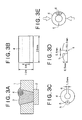
- FIG. 3 (a) is a cross sectional view schematically illustrating the position and direction of the collected cylindrical test pieces from the weld metal ;
- FIG. 3 (b) is a side view illustrating the shape of the cylindrical test pieces,
- FIG. 3 (c) is a cross sectional view of the same,
- FIG. 3 (d) is a cross sectional view enlargingly illustrating a notch portion A in the cross sectional view ⁇ FIG. 3 (c) ⁇ , and
- FIG. 3 (e) is an outlined explanatory view illustrating a testing method for ring cracking by using the cylindrical test pieces.
- cylindrical test pieces 4 each having a notch and a slit were collected from the upside of final bead of the weld metal 3 that was formed by being encircled with the base material 1, the backing metal plate 2 and the bevel portion so that the notch 5 and the slit 6 as shown in FIG. 3 (c) were positioned on the upside and underside of non heat affected zone for the weld metal, respectively.
- the cylindrical test pieces 4 measured 20 mm of longitudinal length, 10 mm of outside diameter and 5 mm of inside diameter. As illustrated in FIG. 3 (c), the cylindrical test pieces 4 were equipped each with a slit 6 having 1.0 mm width and reaching the hollow portion inside the cylinder in the longitudinal direction of the test pieces 4, and with a notch 5 in the longitudinal direction thereof on the outer periphery of the opposite side of the slit 6.
- FIG. 3 (d) which is a cross sectional view enlargingly illustrating a notch portion A in the cross sectional view ⁇ FIG. 3 (c) ⁇
- the notch 5 was a U - shaped groove measuring 0.5 mm of depth, 0.4 mm of width and 0.2 mm of curvature radius at the bottom.
- the test pieces in such a shape were used for the ring cracking test.
- test pieces having a tensile strength at room temperature (20°C) of at least 600 N / mm 2 and that at a high temperature (454°C) of at least 507 N / mm 2 were regarded as being good.
- test pieces having a transition temperature vTr at which absorption energy after SR treatment indicated 55 J being -80°C or lower and also having difference between the transition temperature vTr and the transition temperature vTr' at which absorption energy after step cooling indicated 55 J ; ⁇ vTr (vTr - vTr') being 20°C or lower were regarded as being good.
- test pieces having creep strength under 550°C and 1000 hours being at least 210 N / mm 2 were regarded as being good.
- test pieces which didn't generate cracking in the bottom of U - shaped groove after subjected to SR treatment were regarded as being good, and test pieces which generated cracking therein after SR treatment were regarded as being failure. The results of testing are collectively given in Table 7.
- the content of Mn in the weld metal was lower than the lower limit as stipulated by the present invention, whereby the strength was lowered, and the transition temperature vTr was higher than -80°C.
- the content of Ni in the weld metal exceeded the upper limit as stipulated by the present invention, whereby the tempering brittleness characteristics were worsened.
- Shield arc welding rods (W 30 to W36) having the chemical components and shield rate as given in the following Table 10 were prepared by coating outer periphery of core wires having the chemical components compositions as given in the following Table 8 (each measuring 4.0 mm of diameter and 400 mm of length) with a flux (lagging material: F 2 to 8) having the chemical components compositions as given in the following Table 9.
- Arc welding was carried out under the welding conditions shown in Table 11 by the use of the above - prepared welding rods, in which use was made of the base materials having the symbol P1 in the preceding Table, and the bevel geometry was same as in FIG. 1. Evaluations were made of the characteristics of the weld metals thus obtained. The chemical compositions are given in Table 12, and the results of characteristics tests in Table 13. Table 11 SAW welding conditions Polarity Current (A) Voltage (V) Welding speed (cm/min) Heat input (kJ/cm) Preheat/Interpass temperature (°C) AC 170 24 10.5 23 220 - 225
- the content of V in the weld metal exceeds the upper limit stipulated by the present invention, whereby the transition temperature vTr was higher than -80°C, and SR cracking resistance was worsened.
- EV value is less than the lower limit stipulated by the formula (1), whereby the number of carbides was excessively large, the transition temperature vTr was higher than -80°C, and SR cracking resistance was worsened.
Landscapes
- Engineering & Computer Science (AREA)
- Chemical & Material Sciences (AREA)
- Mechanical Engineering (AREA)
- Theoretical Computer Science (AREA)
- Physics & Mathematics (AREA)
- General Engineering & Computer Science (AREA)
- Materials Engineering (AREA)
- Crystallography & Structural Chemistry (AREA)
- Thermal Sciences (AREA)
- Metallurgy (AREA)
- Organic Chemistry (AREA)
- Child & Adolescent Psychology (AREA)
- General Physics & Mathematics (AREA)
- Health & Medical Sciences (AREA)
- Inorganic Chemistry (AREA)
- Computer Hardware Design (AREA)
- Quality & Reliability (AREA)
- Arc Welding In General (AREA)
- Nonmetallic Welding Materials (AREA)
Abstract
Description
- The present invention relates to a weld metal to be used for welding a high -strength steel material such as Cr - Mo - V steel (Cr: 2.0 to 3.25 mass% (referred to as %, hereinafter), Mo: 0.9 to 1.2%, V: 0.2 to 0.35%). More particularly, itpertains to technology for forming by arc welding method, a weld metal applicable to a steel material which is employed in cold districts and is required to have low temperature toughness.
- As a raw material for structures such as boilers and chemical reaction vessels, there is used the above - mentioned Cr -Mo steel which contains Cr and/or Mo and is excellent in requisite characteristics such as heat resistance and pressure tightness taking into consideration the working environment of a high temperature and high pressure. In addition, in the case of being employed for the foregoing purpose, Cr -Mo steel is also required to be excellent in high temperature strength (particularly, high temperature creep strength ) along with toughness.
- Various structures as mentioned above are constructed by a variety of arc welding methods and in particular, those having large size and/or thickness are generally constructed by submerged arc welding having favorable welding efficiency. Since there is a tendency in recent years that operational conditions are brought up to further high temperature and high pressure in order to contrive highly efficient operations of installations, the use of conventional steels becomes unpractical because of weld structures that have further large thickness, and thus markedly increased material costs and production expenses. Accordingly for the purpose of suppressing large thickness of structures under high temperature and high pressure, high - strength Cr - Mo steel incorporated with V is developed.
- On the other hand, in the case of welding the above - mentioned steel material as a base material, a weld metal to be formed is required to be superior to previous ones in terms of strength at room temperature and elevated temperatures, toughness, creep strength, tempering brittleness resistance characteristic (to be lessened in brittleness in use in a high temperature environment) and SR cracking resistance (to be less liable to cause intergranular cracking due to precipitation aging). In particular, weld structures made of Cr - Mo - V steel have created a serious problem of intergranular cracking due to precipitation aging so - called SR cracking. Hence an important theme is that the Cr - Mo - V steel be excellent in such characteristics (SR cracking resistance).
- In this connection, it is known in particular that regarding the characteristics required of weld metal for weld structure made of high - strength Cr - Mo - V steel, the toughness after an SR treatment and tempering brittleness resistance characteristic are improved by lowering oxygen content in the weld metal. For instance,
Patent Literature 1 discloses that the toughness of the weld metal is enhanced through decreased oxygen content by bringing Si content in the weld metal up to at least 0. 10%. - On the other hand,
Patent Literature 2 discloses that increased oxygen content in weld metal for high - strength Cr - Mo - steel increases intergranular surfaces by the precipitation of dense texture along grain boundaries, and thus enables the formation of a weld metal superior to a weld metal having lower oxygen content in terms of SR cracking resistance. This technology improves SR cracking resistance by bringing the oxygen content to 0. 030 to 0.060%, and compensates for toughness lowering by optimizing the contents of carbon and Mn in the weld metal. - As mentioned above, oxygen shows conflicting behavior in regard to toughness and SR cracking resistance, and therefore the control of oxygen content alone makes it difficult to reconcile both toughness and SR cracking resistance, whereby it follows that either of the characteristic deteriorates.
- Investigations and research have previously been accumulated by the present inventors in order to improve both the characteristics of SR cracking resistance and toughness regarding a weld metal for high - strength Cr - Mo - steel. As one portion of the research, it has been discovered that a weld metal which is simultaneously excellent in toughness and SR cracking resistance can be steadily materialized by properly specifying the chemical composition of the weld metal and optimizing the texture thereof through regulation of SR conditions (stress relieving treatment conditions) without increasing the oxygen content in the weld metal. As the technological significance of the discovery and invention were recognized, the invention was previously applied for a patent (refer to Patent literature 3).
- The development of the above - mentioned technology has enabled to realize the weld metal improved in both toughness and SR cracking resistance. However some problems remain unsolved in that a weld structure to be employed in further cold districts has not sufficient low temperature toughness.
- [Patent literature 1] Japanese Patent Application Laid - Open No. 71196 / 1986 (Showa 61), Claim
- [Patent literature 2] Japanese Patent Application Laid - Open No. 328292 / 1994 (Heisei 6), Claim
- [Patent literature 3] Japanese Patent Application Laid - Open No. 192881 / 1997 (Heisei 9), Claim
- The object of the present invention that has been made under such circumstances is to provide a weld metal which is used for high - strength Cr - Mo - steel and which is improved in toughness (particularly low temperature toughness) and SR cracking resistance as well, while maintaining its high - temperature strength.
- The gist and summary of the weld metal having enabled to solve the above - mentioned theme reside in a weld metal which is formed by an arc welding method and which comprises 0.02 to 0.10% of C (% by mass ; the same holds also hereinafter), 0.05 to 0.4% of Si, 0.3 to 1.2% of Mn, 0.8 to 3.25% of Cr, at most 2% (inclusive of 0% ) of Mo , 0.30 to 1.0% of V, at most 0.03% of N, while suppressing the contents of Al, Ti and Ni to at most 0.03%, at most 0.03% and at most 0.40% respectively, wherein the sum total ( [Mn] + [Ni] ) of Mn content [Mn] and Ni content [Ni] is at most 1.2%, the balance is Fe and inevitable impurities, the contents of P, S, Sn, As and Sb among the inevitable impurities are suppressed each to atmost 0.01%, the content of O is suppressed to at most 0.040%, EV value as defined by the following formula (1) satisfies EV ≥ 0.00, and the number of carbides which have an equivalent circle diameter of at least 0.2 µm and which are present in non heat affected zone of the weld metal after being subjected to stress relieving annealing at 625°C for 10 hours is at most 1.0 number/µm2

- The above - mentioned equivalent circle diameter is determined by a diameter of a circle the area of which is assumed to be equal to that of precipitate, paying attention to the size of the precipitate. It is also the circle diameter that is recognized by means of replica method on an observation surface with a transmission type electron microscope.
- It is preferable as well to incorporate at need, in the weld metal according to the present invention, at least one species selected from the group consisting of (a) at most 0.10% (excluding 0%) of Nb, at most 0.10% (excluding 0%) of Zr, at most 0.10% (excluding 0%) of Hf and at most 0.10% (excluding 0%) of Ta ; (b) at most 2.0% (excluding 0%) of W and/or at most 2.0% (excluding 0%) of Co ; (c) at most 0.015% (excluding 0%) of B ; and the like element. According to the kind of the component to be incorporated, the characteristics of the weld metal are further improved.
- FIG. 1 is across sectional view schematically illustrating bevel geometry of a base material to be used in working examples;
- FIG. 2 is a graph showing SR conditions by plotting temperature in ordinate and period of time in abscissa; and
- FIG. 3 is an explanatory figure showing the procedure of testing method for SR cracking resistance called ring cracking test.
- Research and investigation were previously made by the present inventors on the cause of SR cracking. As a result, it was discovered that SR cracking resistance is lowered as cementites (M3C) which precipitates in old prior austenite grain boundaries is precipitated in a large amount (refer to the Patent literature 3) . The precedently proposed technique by the present inventors has improved SR cracking resistance through decreasing M3C from the above-mentioned viewpoint. In this case, the M3C is a compound of M (metallic element) and C (carbon) in which M is constituted principally of Fe and Cr.
- Nevertheless it has been proved that in order to further improve SR cracking resistance, lowering of other M7C3 and M23C6 which precipitate in lump form (M and C are as previously defined) is necessary as well as lowering of the cementite.
- On the other hand, it has been thought that from the weld metal which is for high - strength Cr - Mo - steel and in which addition of V is indispensable, fine MX (M is mainly V) precipitates at the time of SR treatment, and accordingly such precipitates hinder the improvement in toughness (particularly, low temperature toughness) thereby making it difficult to further improve the toughness ; and also that since an increase in V to be added brings about an increase in the precipitate of MX, the toughness is conversely lowered.
- However, research and investigations made by the present inventors proved that excessively incorporated amount of V against C and N {under-mentioned formula (1)} leads to an increase in an amount of V that forms a solid solution with weld metal matrix, causing large and coarse MX, whereby the toughness is markedly improved by reason of the foregoing. Moreover it has been discovered that it is possible to eliminate not only the M3C but also M7C3 and M23C6 almost entirely and thereby to improve not only the toughness but also SR cracking resistance. According to the present invention "M" in formula "MX" represents alloying metal elements such as V, Nb, Ti and/or Mo. "X" in formula "MX" represents C and/or N. In a preferred embodiment "MX" means the carbide, nitride or carbonitride having a crystal structure of sodium chloride structure.
- In addition, it has also been proved that since SR cracking is most liable to take place in brittle zone at 625°C, the morphology of carbide precipitates when subjected to a heat treatment at 625°C for 10 hours (SR treatment) becomes an important requirement for improvement in the characteristics. The morphology of carbide precipitates in the weld metal, which is influenced not only by the chemical composition of the weld metal but also the cooling rate and deoxidizing state and the like, can not be unequivocally determined. In view of the above, investigations were made by the present inventors on the correlation among the morphology of carbide precipitates , SR cracking resistance and low temperature toughness on the basis of the morphology of carbide precipitates after the heat treatment at 625°C for 10 hours ( SR treatment). As a result, it has turned out that in the case where the number of large coarse precipitates each having an equivalent circle diameter of at least 0.2 µm is at most 1.0 number/µm2, both SR cracking resistance and low temperature toughness are improved.
- It is necessary in the weld metal according to the present invention to satisfy the above-mentioned requirements, and at the same time to properly regulate the fundamental chemical composition. The reasons for limiting the scope of each of the elements are as follows.
- C, which exerts a great influence on quenching hardenability, is an important element for assuring toughness and strengths at room temperature and elevated temperature. The content of C in the weld metal, when being less than 0. 02%, results in lowered strength, etc., whereas the content thereof, when being more than 0.10%, brings about excessively high strength, thus markedly lowers the toughness. Hence the content of C therein needs to be in the range of 0.02 to 0.10%. From the aspect of improving the characteristic, the lower and upper limits of the contents thereof are preferably 0.04% and 0.08%, respectively.
- Si, which has deoxidizing effect, exhibits an effect on controlling the amount of oxygen in the weld metal. In order to make Si to exhibit such effect, the content of Si needs to be at least 0.05%, but when exceeding 0.4% being excessively high, causes deterioration in tempering brittleness characteristics and SR cracking resistance, and besides brings about excessively high strength, thus contributing to lowered toughness. The lower and upper limits of the contents thereof are preferably 0.10% and 0.30%, respectively.
- As is the case with C, Mn exerts effects on enhancing high temperature strength and toughness of the weld metal, and has a function of controlling oxygen amount in the weld metal by deoxidizing action. In order to make Mn to exhibit such effects, the content of Mn needs to be at least 0.3%, but when exceeding 1.2% being excessively high, causes deterioration in creep strength, tempering brittleness resistance characteristic and SR cracking resistance. Hence the content of Mn in the weld metal needs to be 0.3 to 1.2%, and the lower and upper limits of the contents thereof are preferably 0.5% and 1.0%, respectively.
- Cr and Mo are each a fundamental component for high - strength 2.25 to 3% Cr - 1% Mo steel. When the content of Cr in the weld metal is less than 0.8% or more than 3.25%, or the content of Mo in the weld metal is more than 2.0%, the working effects of the present invention are recognized. However, the above -mentioned scope of the base - material components is not practically employed in a high temperature environment as an object. Therefore the content of Cr is set on 0.8 to 3.25%, and that of Mo on at most 2.0%. The lower and upper limits of the content of Cr are preferably 2.0% and 3.0%, respectively, while the upper limit of the content of Mo is preferably 1.5%. In the present invention, the use of Cr - Mo steel as a base material is fundamentally assumed, however a base material is not restricted to the Cr - Mo steel, but can be selected for use from steels such as Cr steel which exhibits the characteristics similar to those of the Cr - Mo steel. Thus the lower limit of the content of Mo is set on 0%.
- V is a principal element which constitutes MX, and is an effective element for exhibiting an effect on improving creep characteristics, suppressing the formation of large coarse carbides such as M7C3 and M23C6 that are responsible for SR cracking, and improving SR cracking resistance. In order to make V to exhibit such effects, the content thereof needs to be at least 0.3%, but the content excessively exceeding 1.0% causes the MX to be unreasonably large and coarse, thereby losing the effect of improving the creep characteristics. Hence the content of V is set on 0.30 to 1.0%. The lower limit of the contents thereof ispreferably 0.40%, more preferably 0.50%, while the upper limit thereof is preferably 0.80%, more preferably 0.70%.
- N exhibits an effect on enhancing the creep strength of the weld metal. However the content of N, when excessively exceeds 0.030%, results in deterioration in toughness. The upper limit of the content of N is preferably 0.015%.
- Al and Ti, which impair toughness of the weld metal, needs to be minimized. Any of the content of Al and that of Ti, when exceeding 0.03%, gives rise to markedly lowered toughness, and accordingly needs to be suppressed to at most 0.03%, preferably at most 0.01%.
- Ni has an action of promoting tempering brittleness, particularly intensifying the action when the content of Ni in the weld metal exceeds 0.40%, and accordingly the content of Ni therein needs to be at most 0.40%, preferably at most 0.20%.
- When the sum total of the content of Mn [Mn] and the content of Ni [Ni] ([Mn] + [Ni]) exceeds 1.2%, deterioration in tempering brittleness resistance characteristics becomes remarkable, and thus the upper limit is set on 1.2%. The sum total [Mn] + [Ni] is preferably at most 1.0%.
- The fundamental chemical composition in the weld metal relating to the present invention is as described hereinbefore. The balance is composed of Fe and inevitable impurities, of which P, S, Sn, As, Sb and O are suppressed preferably as follows. The reasons for limiting the scope of each of the impurities are as follows.
- These elements are each an impurity which is inevitably mingled in the weld metal. High contents thereof are responsible for occurrence of SR cracking and tempering brittleness. Accordingly P, S, Sn, As and Sb contained as inevitable impurities in the weld metal are each suppressed to at most 0.01%, preferably at most 0.006%.,
- O is a detrimental component which mingles in the weld metal, and worsens toughness. In particular when the content of O exceeds 0.040%, the toughness is greatly worsened, and hence the upper limit thereof is set on 0.040%. The improvement in the toughness increases with a decrease in the content of O. However in order to prevent deterioration in welding workability such as poor bead form, the lower limit thereof is set on 0.020%, approximately.
- It is preferable as well to incorporate at need, in the weld metal according to the present invention, at least one species selected from the group consisting of (a) at most 0.10% (exclusive of 0%) of Nb, at most 0.10% (exclusive of 0%) of Zr, at most 0.10% (exclusive of 0%) of Hf and at most 0.10% (exclusive of 0%) of Ta ; (b) at most 2.0% (exclusive of 0%) of W and/or at most 2.0% (exclusive of 0%) of Co ; (c) at most 0.015% (exclusive of 0%) of B ; and the like element. According to the kind of the component to be incorporated, the characteristics of the weld metal are further improved.
- By incorporating at least one of Nb, Zr, Hf and Ta in the weld metal, there is obtainable an effect on further improving SR cracking resistance of the weld metal. These elements enhance Cr activity and lower C activity, and the precipitation of M3C, M7C3 and M23C6 is markedly suppressed, thereby enabling to improve SR cracking resistance. Nevertheless any of the above -mentioned elements, when the content thereof exceeds 0.10%, gives rise to unreasonably high strength and lowered toughness. For this reason in the case of incorporating any of the elements, the content thereof is preferably at most 0.10%. Preferable lower limit for each is about 0.05%.
- By incorporating at least one of W and Co in the weld metal, strengths at room temperature and elevated temperature and creep strength can further be enhanced in comparison with incorporation of V alone. However any of the elements in question, when the content thereof exceeds 2.0%, gives rise to unreasonably high strength and lowered toughness. For this reason, in the case of incorporating any of the elements, the content thereof is preferably at most 2.0%. Preferable lower limit for each is about 1.5%.
- Although B exerts an effect on stabilizing improving toughness, content thereof exceeding 0.015% brings about not only unreasonably high strength and lowered toughness, but also high susceptibility to high temperature cracking upon welding. For this reason, in the case of incorporating B, the content thereof is preferably at most0.015%. Preferable lower limit of B is about 0.010%.
- Importance is attached also to the requirement that EV value as defined by the following formula (1) satisfies EV ≥0.00, and the content of the carbide which has an equivalent circle diameter of at least 0.2 µm and which is present in non heat affected zone of the weld metal after being subjected to stress relieving annealing at 625°C for 10 hours is atmost 1.0 number/µm2, where

- The EV as defined by the formula (1) points out the degree of excess V for C and N. The EV, when being 0.00 or greater, causes excess V and large coarseMX, enabling to improve toughness and lowers the compounds that worsen SR cracking resistance such as M7C3 and M23C6. The EV is preferably at least 0.10, more preferably at least 0.20. Conversely unreasonably high EV brings about deterioration in creep strength, and hence the upper limit is set preferably on 0. 65, more preferably on at most 0.50.
- SR cracking resistance deteriorates by the presence of carbides having an equivalent circle diameter of 0.2µm or larger. The number of such carbides in excess of 1.0 number/µm2 leads to incapability of assuring desirable SR cracking resistance. In view of the foregoing, the number of such carbides needs to be at most 1.0 number/µm2, preferably at most 0.5 number/µm2, more preferably 0.0 number/µm2.
- A welding method on forming the weld metal in the present invention is not specifically limited provided that it is an arc welding method, but may be selected for application from submerged arc welding (SAW) as will be stated hereinafter in the working examples, shield metal arc welding (SMAW), tungsten inert gas (TIG) welding and gas shield arc welding (MAG, MIG) and the like.
- In the present invention as described hereinbefore, the characteristics of the weld metal is improved by properly controlling chemical composition of the weldmetal and the number of carbides. The chemical composition of the weld metal is influenced by the welding conditions upon arc welding such as the chemical composition of welding wires, welding current, welding voltage and wire extension, and besides the chemical composition of base material, bevel geometry and the like, while the welding conditions are influenced by the chemical composition of welding wires. For these reasons, the ranges of the chemical composition of weld wires, welding conditions, the chemical composition of base material and the like for the purpose of assuring the weld metal composition according to the present invention are not unequivocally determined. Inbrief, the objects of the present invention are achieved by combining the above - mentioned factors so as to obtain the weld metal as stipulated according to the present invention.
- The working effects and advantages of the present invention are summarized in the following. The invention has made it possible to realize high - strength weld metal for Cr - Mo steel by improving not only toughness, particularly low temperature toughness but also SR cracking resistance while assuring high temperature strength, and by optimizing the chemical composition as described hereinbefore so as to decrease the number of carbides present in non heat affected zone of the weld metal.
- In the following, the present invention will be described in more detail with reference to working examples, which however shall never limit the invention thereto. Any of modification in design in the light of the above - or under - mentioned gist or summary falls within the scope of the present invention.
- FIG. 1 is a cross sectional view schematically showing bevel geometry of
base metal 1 to be used in the present invention, which is as shown in FIG. 1, has a bevel in the form of "V" and is equipped beneath the bevel with abacking plate 2 having the chemical composition same as that of theweld base metal 1. - In the Example, the angle of bevel in the form of "V" was set at 10 degrees, the width of gap where the backing plate is located on the underside was set at 25mm, and the thickness of the
base metal 1 was set at 25 mm. The chemical compositions of the base metal used therein are given in Table 1.Table 1 Symbol Chemical compositions (% by mass) of base materials C Si Mn P S Cr Mo V Nb Fe P1 0.11 0.07 0.56 0.004 0.002 2.39 1.00 0.32 0.025 Bal. P2 0.12 0.08 0.55 0.005 0.002 3.01 0.99 0.42 0.023 Bal. - Weld metals were prepared by using the
weld base metal 1 of bevel geometry shown in FIG. 1, combining various bond fluxes having chemical compositions shown in the following Table 2 with solid wires having chemical compositions shown in the following Table 3 and carrying out welding under the welding conditions (tandem welding system) indicated in the following Table 4. The chemical compositions of the weld metal thus obtained are given in the following Table 5.Table 2 Symbol Chemical compositions (% by mass) of bond flux SiO2 MgO Al2O3 CaF2 CaCO3 P Others F1 12 32 17 0.04 0.04 0.002 2 
Table 4 SAW welding conditions Polarity Electrode Current (A) Voltage (V) Welding speed (cm/min) Heat input (kJ/cm) Preheat/Interpass temperature (°C) AC Precedent 510 28 55 33.9 220 - 225 Subsequent 560 30 
- Subsequently the weld metals thus obtained were heat treated at 625°C for 10 hours (SR treatment, temperature raising / lowering rate being 25 °C/ hr), and the resultant carbides were observed through TEM - extraction replica method for non heat affected zone of final pass of the weld metals after the SR treatment. At this time, a region of 8.5µm2 was photographed for 10 visual fields at 15000 magnification to count the number of carbides having an equivalent circle diameter of 0.2µm or larger by the use of an image analysis software.
- Subsequently test pieces intended for conducting various mechanical characteristics testing were collected from part of the weld metal, in which the contents of the characteristics testing included tensile tests at room temperature (20°C) and a high temperature, Charpy impact test, tempering brittleness test and creep rupture test, making a total of four tests. The test pieces used for these tests, which were of the shape as pointed out in the following Table 6, were collected from the middle of plate thickness of the testing material that was heat treated under SR treatment as combinationally shown in Table 6.
Table 6 Contents of test SR treatment conditions (°C x hour) Test piece collection position Test piece shape Tensile test Room temperature 700 x 26 Middle of plate thickness JIS Z 3111 No. A1 454°C 700 x 26 JIS G 0567 (6 mmΦ) Charpy impact test 700 x 7 JIS Z 3111 No. 4 Tempering brittleness test 700 x 7 + step cooling JIS Z 3111 No. 4 Creep rupture test 700 x 26 JIS Z 2273 (6 mmΦ) - Among the above - mentioned testing, the tempering brittleness test was subjected to a step cooling treatment in addition to the prescribed SR treatment.
- FIG. 2 is a graph showing the step cooling treatment by plotting temperature in ordinate and time in abscissa. As illustrated in FIG. 2, when the temperature of a test piece exceeded 300°C, heating conditions were regulated so that the temperature rise rate was made to 50°C / hr or less, and the test pieces were heated up to 593°C and maintained thereat for one hour. Thereafter in the same manner as above, the test pieces were maintained at 538°C for 15 hours, at 524°C for 24 hours and at 496°C for 60 hours, while in this cooling stage the rate of cooling the test pieces were regulated to 5.6°C/hr. Further the test pieces that had been maintained at 496°C were cooled at 2.8°C/ hr down to 468°C, at which it they were maintained for 100 hours. Subsequently the test pieces were cooled at a cooling rate of 28°C/ hr down to 300°C.
- In addition, cylindrical test pieces for the purpose of ring cracking test to evaluate SR cracking resistance were collected from the above - stated weld metal. FIG. 3 (a) is a cross sectional view schematically illustrating the position and direction of the collected cylindrical test pieces from the weld metal ; FIG. 3 (b) is a side view illustrating the shape of the cylindrical test pieces, FIG. 3 (c) is a cross sectional view of the same, FIG. 3 (d) is a cross sectional view enlargingly illustrating a notch portion A in the cross sectional view {FIG. 3 (c)}, and FIG. 3 (e) is an outlined explanatory view illustrating a testing method for ring cracking by using the cylindrical test pieces.
- As illustrated in FIG. 3 (a),
cylindrical test pieces 4 each having a notch and a slit were collected from the upside of final bead of theweld metal 3 that was formed by being encircled with thebase material 1, the backingmetal plate 2 and the bevel portion so that thenotch 5 and theslit 6 as shown in FIG. 3 (c) were positioned on the upside and underside of non heat affected zone for the weld metal, respectively. - As illustrated in FIG. 3 (b), the
cylindrical test pieces 4 measured 20 mm of longitudinal length, 10 mm of outside diameter and 5 mm of inside diameter. As illustrated in FIG. 3 (c), thecylindrical test pieces 4 were equipped each with aslit 6 having 1.0 mm width and reaching the hollow portion inside the cylinder in the longitudinal direction of thetest pieces 4, and with anotch 5 in the longitudinal direction thereof on the outer periphery of the opposite side of theslit 6. - Further as illustrated in FIG. 3 (d) which is a cross sectional view enlargingly illustrating a notch portion A in the cross sectional view {FIG. 3 (c)}, the
notch 5 was a U - shaped groove measuring 0.5 mm of depth, 0.4 mm of width and 0.2 mm of curvature radius at the bottom. The test pieces in such a shape were used for the ring cracking test. - In the ring cracking test, bending stress was applied to the
cylindrical test pieces 4 in the direction shown by arrows as illustrated in FIG. 3 (e) with reference to " Research on stress relief annealing cracking" second edition " ( by Kiuchi et al, bulletin of Institute for Welding, vol. 33, No. 9 (1964), p.718), theslit 6 of each of the test pieces was subjected to TIG welding without the use of a filler metal, and a heat treatment was performed with residual tensile stress being caused as such in the bottom of the U - shaped groove. Thus SR cracking property was judged by the existence of SR cracking in the bottom of the U - shaped groove. - In the following, some description will be given of evaluation criteria in a variety of evaluation testing. In the first place regarding strength, test pieces having a tensile strength at room temperature (20°C) of at least 600 N / mm2 and that at a high temperature (454°C) of at least 507 N / mm2 were regarded as being good. Concerning the Charpy impact test which evaluates toughness and tempering brittleness characteristics, test pieces having a transition temperature vTr at which absorption energy after SR treatment indicated 55 J being -80°C or lower and also having difference between the transition temperature vTr and the transition temperature vTr' at which absorption energy after step cooling indicated 55 J ; ΔvTr (vTr - vTr') being 20°C or lower were regarded as being good.
- Concerning the creep rupture test, test pieces having creep strength under 550°C and 1000 hours being at least 210 N / mm2 were regarded as being good. Regarding the ring cracking test evaluating SR cracking resistance, test pieces which didn't generate cracking in the bottom of U - shaped groove after subjected to SR treatment were regarded as being good, and test pieces which generated cracking therein after SR treatment were regarded as being failure. The results of testing are collectively given in Table 7.

- From the results described above, the following is taken into consideration. It is understood that Nos. 1 to 17, which met the requirements as stipulated by the present invention, are excellent in both SR cracking resistance and toughness. As opposed thereto, Nos. 18 to 30, which were devoid of any of the requirements as stipulated by the present invention, caused deterioration in at least one of SR cracking resistance and toughness.
- Among them in No. 18, the content of C exceeded the upper limit as stipulated by the present invention, and the transition temperature vTr was higher than -80°C, in No. 19, the content of V in the weldmetal was lower than the lower limit as stipulated by the present invention, whereby the number of carbides was excessively large, the transition temperature vTr was higher than -80°C, and besides SR cracking resistance was worsened.
- In Nos. 20, 21, &22, the sum total of the content of Mn [Mn] and the content of Ni [Ni] ([Mn] + [Ni]), the contents of Si and O, and the contents of Mn exceeded the upper limits as stipulated by the present invention, whereby the tempering brittleness characteristics of those were worsened.
- In Nos. 23 &24, the contents of Ti and Al exceeded the upper limits as stipulated by the present invention, whereby the transition temperature vTr revealed markedly high values.
- In Nos. 25 & 26, the EV values were outside the proper range as stipulated by the formula (1), whereby the number of carbides was excessively large, the transition temperature vTr was higher than -80°C, and besides SR cracking resistance was worsened.
- In No. 27, the content of V in the weld metal exceeded the upper limit as stipulated by the present invention, whereby the number of carbides exceeded the upper limit as stipulated by the present invention, the number of carbides was excessively large, and creep characteristics were worsened. In No. 28, the content of Nb to be incorporated was excessively high, and the transition temperature vTr was higher than -80°C.
- In No.29, the content of Mn in the weld metal was lower than the lower limit as stipulated by the present invention, whereby the strength was lowered, and the transition temperature vTr was higher than -80°C. In No.30, the content of Ni in the weld metal exceeded the upper limit as stipulated by the present invention, whereby the tempering brittleness characteristics were worsened.
- Shield arc welding rods (W 30 to W36) having the chemical components and shield rate as given in the following Table 10 were prepared by coating outer periphery of core wires having the chemical components compositions as given in the following Table 8 (each measuring 4.0 mm of diameter and 400 mm of length) with a flux (lagging material:
F 2 to 8) having the chemical components compositions as given in the following Table 9.
- Arc welding was carried out under the welding conditions shown in Table 11 by the use of the above - prepared welding rods, in which use was made of the base materials having the symbol P1 in the preceding Table, and the bevel geometry was same as in FIG. 1. Evaluations were made of the characteristics of the weld metals thus obtained. The chemical compositions are given in Table 12, and the results of characteristics tests in Table 13.
Table 11 SAW welding conditions Polarity Current (A) Voltage (V) Welding speed (cm/min) Heat input (kJ/cm) Preheat/Interpass temperature (°C) AC 170 24 10.5 23 220 - 225 
- It is clearly understood from Table 13 that the items which satisfy all the requirements stipulated by the present invention (Nos. 31 to 35) are excellent in SR cracking resistance and toughness, whereas either item which is devoid of any of the requirements stipulated by the present invention (Nos. 36 & 37) are inferior in at least one characteristic of SR cracking resistance and toughness.
- Specifically in No. 36, the content of V in the weld metal exceeds the upper limit stipulated by the present invention, whereby the transition temperature vTr was higher than -80°C, and SR cracking resistance was worsened. In No. 37, EV value is less than the lower limit stipulated by the formula (1), whereby the number of carbides was excessively large, the transition temperature vTr was higher than -80°C, and SR cracking resistance was worsened.
Claims (4)
- A weld metal excellent in low temperature toughness and SR cracking resistance which is used for high - strength Cr - Mo steel, which is formed by an arc welding method, and which comprises
0.02 to 0.10% of C (% by mass; the same holds also hereinafter),
0.05 to 0.4% of Si,
0.3 to 1.2% of Mn,
0.8 to 3.25% of Cr,
at most 2% (inclusive of 0%) of Mo,
0.30 to 1.0% of V, and
at most 0.03% of N,
wherein
the contents of Al, Ti and Ni are suppressed to at most 0.03%, at most 0.03% and at most 0.40%, respectively;
sum total ([Mn] + [Ni]) of Mn content [Mn] and Ni content [Ni] is at most 1.2%;
the balance is Fe and inevitable impurities; the contents of P, S, Sn, As and Sb among the inevitable impurities are suppressed each to at most 0.01%;
the content of O is suppressed to at most 0.040%;
EVvalue as defined by the following formula (1) satisfies EV ≥ 0.00; and
the number of carbides which have an equivalent circle diameter of at least 0.2 µm and which are present in non heat affected zone of the weld metal after being subjected to stress relieving annealing at 625°C for 10 hours is at most 1.0 number/µm2
- The weld metal for high - strength Cr - Mo steel as set forth in Claim 1, which further comprises at least one species selected from the group consisting of at most 0.10% (exclusive of 0%) of Nb, at most 0.10% (exclusive of 0%) of Zr, at most 0.10% (exclusive of 0%) of Hf and at most 0.10% (exclusive of 0%) of Ta.
- The weld metal for high - strength Cr - Mo steel as set forth in Claim 1 or 2, which further comprises at least one species selected from the group consisting of at most 2.0% (exclusive of 0%) of W and at most 2.0% (exclusive of 0%) of Co.
- The weld metal for high - strength Cr - Mo steel as set forth in any of Claims1 to 3, which further comprises at most 0.015% (exclusive of 0%) of B.
Applications Claiming Priority (1)
| Application Number | Priority Date | Filing Date | Title |
|---|---|---|---|
| JP2005041092A JP2006225718A (en) | 2005-02-17 | 2005-02-17 | DEPOSITED METAL FOR HIGH STRENGTH Cr-Mo STEEL HAVING EXCELLENT LOW TEMPERATURE TOUGHNESS AND SR CRACK RESISTANCE |
Publications (2)
| Publication Number | Publication Date |
|---|---|
| EP1693143A1 true EP1693143A1 (en) | 2006-08-23 |
| EP1693143B1 EP1693143B1 (en) | 2014-09-17 |
Family
ID=36337643
Family Applications (1)
| Application Number | Title | Priority Date | Filing Date |
|---|---|---|---|
| EP06002363.7A Expired - Lifetime EP1693143B1 (en) | 2005-02-17 | 2006-02-06 | Weld metal of low temperature toughness and SR cracking resistance used for high-strength Cr-Mo steel |
Country Status (5)
| Country | Link |
|---|---|
| US (1) | US20060179974A1 (en) |
| EP (1) | EP1693143B1 (en) |
| JP (1) | JP2006225718A (en) |
| KR (1) | KR100748810B1 (en) |
| CN (1) | CN100419110C (en) |
Cited By (6)
| Publication number | Priority date | Publication date | Assignee | Title |
|---|---|---|---|---|
| EP1958729A1 (en) * | 2007-02-19 | 2008-08-20 | Kabushiki Kaisha Kobe Seiko Sho | Weld metal of high-strength Cr-Mo steel |
| US20130315661A1 (en) * | 2011-03-11 | 2013-11-28 | Kabushiki Kaisha Kobe Seiko Sho (Kobe Steel,Ltd.) | Weld metal highly resistant to temper embrittlement |
| EP2674241A4 (en) * | 2011-02-09 | 2015-03-11 | Kobe Steel Ltd | Weld metal with excellent creep characteristics |
| EP2783790A4 (en) * | 2011-11-21 | 2015-03-11 | Kobe Steel Ltd | Weld metal having excellent temper embrittlement resistance |
| EP2952285A4 (en) * | 2013-02-04 | 2016-06-22 | Kobe Steel Ltd | SUBMERGED ARC WELDING WIRE FOR HIGH-STRENGTH 2.25Cr-1Mo-V STEEL AND WELD METAL |
| EP2965856A4 (en) * | 2013-03-07 | 2016-07-13 | Kobe Steel Ltd | Welded metal and welded structure |
Families Citing this family (16)
| Publication number | Priority date | Publication date | Assignee | Title |
|---|---|---|---|---|
| MX2008006132A (en) * | 2005-11-10 | 2008-10-23 | Wolverine Tube Inc | Brazing material with continuous length layer of elastomer containing a flux. |
| JP4673822B2 (en) * | 2006-11-14 | 2011-04-20 | 新日本製鐵株式会社 | Refractory steel material excellent in toughness of welded joint and method for producing the same |
| JP4902489B2 (en) * | 2007-02-19 | 2012-03-21 | 株式会社神戸製鋼所 | High strength Cr-Mo steel weld metal |
| US8715432B2 (en) * | 2008-03-31 | 2014-05-06 | Nippon Steel & Sumitomo Metal Corporation | Fire-resistant steel superior in weld joint reheat embrittlement resistance and toughness and method of production of same |
| JP5022428B2 (en) * | 2009-11-17 | 2012-09-12 | 株式会社神戸製鋼所 | MIG arc welding wire for hardfacing and MIG arc welding method for hardfacing |
| JP5611006B2 (en) * | 2010-11-24 | 2014-10-22 | 株式会社神戸製鋼所 | Weld metal and submerged arc welding method |
| US9259806B2 (en) * | 2012-05-08 | 2016-02-16 | Nippon Steel & Sumitomo Metal Corporation | Flux-cored wire for welding ultrahigh tensile strength steel |
| CN102963146B (en) * | 2012-09-29 | 2015-12-02 | 深圳光韵达光电科技股份有限公司 | A kind of SMT laser template and preparation method thereof |
| CN104907733B (en) * | 2015-07-10 | 2017-10-17 | 中国科学院合肥物质科学研究院 | A kind of Flouride-resistani acid phesphatase low activation steel welding wire for gas shielded welding and preparation method thereof |
| CN105014261B (en) * | 2015-07-30 | 2017-08-04 | 武汉铁锚焊接材料股份有限公司 | A kind of chrome-molybdenum steel seamless metal powder core type flux-cored wire |
| CN106271209B (en) * | 2016-09-13 | 2018-01-12 | 江苏科技大学 | High temperature Fe bases solder and preparation method and soldering processes for soldering 50Mo 50Re alloys |
| CN106399842A (en) * | 2016-12-02 | 2017-02-15 | 武汉钢铁股份有限公司 | Steel for submerged arc welding wire for heat-resistant steel and production method of steel |
| KR102233335B1 (en) * | 2019-02-26 | 2021-03-29 | 고려용접봉 주식회사 | Smaw welded metal having excellent strength |
| CN110714163B (en) * | 2019-11-05 | 2022-01-28 | 僖昴晰(上海)新材料有限公司 | High-hardness steel alloy welding material |
| EP3885070B1 (en) * | 2020-03-26 | 2025-05-14 | Voestalpine Böhler Welding Austria GmbH | Welding material and metal powder filling wire for producing a welding material |
| CN117921251A (en) * | 2022-10-17 | 2024-04-26 | 天津重型装备工程研究有限公司 | 2.25Cr-1Mo-0.25V steel alternating current submerged arc welding material, welding process and cladding metal |
Citations (4)
| Publication number | Priority date | Publication date | Assignee | Title |
|---|---|---|---|---|
| JPS60231591A (en) * | 1984-05-01 | 1985-11-18 | Kobe Steel Ltd | Wire for submerged arc welding of cr-mo group low alloy steel |
| JPS6171196A (en) | 1984-09-13 | 1986-04-12 | Kawasaki Steel Corp | Submerged arc welding method of low cr-mo alloy steel |
| JPH06328292A (en) | 1993-05-24 | 1994-11-29 | Kobe Steel Ltd | Submerged arc welding method for high-strength cr-mo steel |
| FR2740715A1 (en) * | 1995-11-08 | 1997-05-09 | Kobe Steel Ltd | Weld metal bonding pieces of chromium@-molybdenum@ steels |
Family Cites Families (6)
| Publication number | Priority date | Publication date | Assignee | Title |
|---|---|---|---|---|
| JP3258190B2 (en) * | 1994-09-30 | 2002-02-18 | 株式会社神戸製鋼所 | Submerged arc welding method for high strength Cr-Mo steel and weld metal |
| JP3283768B2 (en) * | 1996-10-28 | 2002-05-20 | 株式会社神戸製鋼所 | High strength Cr-Mo steel TIG weld metal and TIG welding method |
| JP3283769B2 (en) * | 1996-10-29 | 2002-05-20 | 株式会社神戸製鋼所 | Gas shielded arc weld metal of high strength Cr-Mo steel and gas shielded arc welding method |
| JP3283773B2 (en) * | 1996-10-31 | 2002-05-20 | 株式会社神戸製鋼所 | High strength Cr-Mo steel coated arc welding metal and coated arc welding method |
| DZ2532A1 (en) * | 1997-06-20 | 2003-02-08 | Exxon Production Research Co | A method of welding a base metal to produce a welded joint and that welded joint. |
| JP4476018B2 (en) * | 2004-05-18 | 2010-06-09 | 株式会社神戸製鋼所 | Improved welding wire for 9Cr-1Mo steel |
-
2005
- 2005-02-17 JP JP2005041092A patent/JP2006225718A/en active Pending
-
2006
- 2006-01-25 US US11/338,701 patent/US20060179974A1/en not_active Abandoned
- 2006-02-06 EP EP06002363.7A patent/EP1693143B1/en not_active Expired - Lifetime
- 2006-02-16 KR KR1020060015290A patent/KR100748810B1/en not_active Expired - Fee Related
- 2006-02-17 CN CNB2006100090465A patent/CN100419110C/en not_active Expired - Fee Related
Patent Citations (5)
| Publication number | Priority date | Publication date | Assignee | Title |
|---|---|---|---|---|
| JPS60231591A (en) * | 1984-05-01 | 1985-11-18 | Kobe Steel Ltd | Wire for submerged arc welding of cr-mo group low alloy steel |
| JPS6171196A (en) | 1984-09-13 | 1986-04-12 | Kawasaki Steel Corp | Submerged arc welding method of low cr-mo alloy steel |
| JPH06328292A (en) | 1993-05-24 | 1994-11-29 | Kobe Steel Ltd | Submerged arc welding method for high-strength cr-mo steel |
| FR2740715A1 (en) * | 1995-11-08 | 1997-05-09 | Kobe Steel Ltd | Weld metal bonding pieces of chromium@-molybdenum@ steels |
| JPH09192881A (en) | 1995-11-08 | 1997-07-29 | Kobe Steel Ltd | Weld metal of high strength cr-mo steel and submerged arc welding method |
Non-Patent Citations (4)
| Title |
|---|
| ICHIKAWA K ET AL: "TOUGHNESS AND CREEP STRENGTH OF MODIFIED 2.25CR-1MO STEEL WEL METAL", WELDING JOURNAL, AMERICAN WELDING SOCIETY, MIAMI, FL, US, vol. 74, no. 7, 1 July 1995 (1995-07-01), pages 230 - S, XP000542810, ISSN: 0043-2296 * |
| PATENT ABSTRACTS OF JAPAN vol. 010, no. 096 (M - 469) 12 April 1986 (1986-04-12) * |
| PATENT ABSTRACTS OF JAPAN vol. 1997, no. 11 28 November 1997 (1997-11-28) * |
| SPENCER P N ET AL: "FRACTURE TOUGHNESS, FATIGUE CRACK PROPAGATION AND CREEP RUPTURE BEHAVIOUR IN THICK SECTION WELDMENTS OF 3CR-MO PRESSURE-VESSEL STEELS DEVELOPED FOR HIGH-TEMPERATURE/HIGH-PRESSURE HYDROGEN SERVICE", HIGH TEMPERATURE TECHNOLOGY, SCIENTIFIC LTD. GUILDFORD, UK, vol. 7, no. 1, 1 February 1989 (1989-02-01), pages 17 - 26, XP000005241 * |
Cited By (9)
| Publication number | Priority date | Publication date | Assignee | Title |
|---|---|---|---|---|
| EP1958729A1 (en) * | 2007-02-19 | 2008-08-20 | Kabushiki Kaisha Kobe Seiko Sho | Weld metal of high-strength Cr-Mo steel |
| US8101029B2 (en) | 2007-02-19 | 2012-01-24 | Kobe Steel, Ltd. | Weld metal of high-strength Cr-Mo steel |
| EP2674241A4 (en) * | 2011-02-09 | 2015-03-11 | Kobe Steel Ltd | Weld metal with excellent creep characteristics |
| US9289859B2 (en) | 2011-02-09 | 2016-03-22 | Kobe Steel, Ltd. | Weld metal with excellent creep characteristics |
| US20130315661A1 (en) * | 2011-03-11 | 2013-11-28 | Kabushiki Kaisha Kobe Seiko Sho (Kobe Steel,Ltd.) | Weld metal highly resistant to temper embrittlement |
| EP2783790A4 (en) * | 2011-11-21 | 2015-03-11 | Kobe Steel Ltd | Weld metal having excellent temper embrittlement resistance |
| US9505087B2 (en) | 2011-11-21 | 2016-11-29 | Kobe Steel, Ltd. | Weld metal having excellent temper embrittlement resistance |
| EP2952285A4 (en) * | 2013-02-04 | 2016-06-22 | Kobe Steel Ltd | SUBMERGED ARC WELDING WIRE FOR HIGH-STRENGTH 2.25Cr-1Mo-V STEEL AND WELD METAL |
| EP2965856A4 (en) * | 2013-03-07 | 2016-07-13 | Kobe Steel Ltd | Welded metal and welded structure |
Also Published As
| Publication number | Publication date |
|---|---|
| KR100748810B1 (en) | 2007-08-13 |
| EP1693143B1 (en) | 2014-09-17 |
| CN1821432A (en) | 2006-08-23 |
| JP2006225718A (en) | 2006-08-31 |
| US20060179974A1 (en) | 2006-08-17 |
| CN100419110C (en) | 2008-09-17 |
| KR20060092146A (en) | 2006-08-22 |
Similar Documents
| Publication | Publication Date | Title |
|---|---|---|
| EP1693143B1 (en) | Weld metal of low temperature toughness and SR cracking resistance used for high-strength Cr-Mo steel | |
| EP1081244B1 (en) | High strength, low alloy, heat resistant steel | |
| JP5157606B2 (en) | TIG welding method of high strength steel using flux cored wire | |
| KR101840914B1 (en) | SUBMERGED ARC WELDING WIRE FOR HIGH-STRENGTH 2.25Cr-1Mo-V STEEL AND WELD METAL | |
| JP4879696B2 (en) | High yield strength, high toughness, flux-cored wire for gas shielded arc welding | |
| US20030201263A1 (en) | Welding material and a method of producing welded joint | |
| US5964964A (en) | Welded joint of high fatigue strength | |
| JP3850764B2 (en) | Welding wire for high Cr ferritic heat resistant steel | |
| JP4441372B2 (en) | High strength and high toughness gas shielded arc welding wire | |
| JP4673710B2 (en) | Two-electrode single-sided one-pass large heat input submerged arc welding method with excellent weld metal toughness | |
| JPH09168891A (en) | Low hydrogen covered electrode for high strength cr-mo steel | |
| EP3133180A1 (en) | Welded metal having excellent strength, toughness and sr cracking resistance | |
| JPH11229075A (en) | High strength steel excellent in delayed fracture resistance and method of manufacturing the same | |
| EP0930127B1 (en) | Welding materials for high-Cr steels | |
| EP2557192A1 (en) | Welding metal having excellent low-temperature toughness and excellent drop-weight characteristics | |
| JP3283773B2 (en) | High strength Cr-Mo steel coated arc welding metal and coated arc welding method | |
| EP2529876B1 (en) | Welding metal having excellent low-temperature toughness and drop-weight characteristics | |
| EP2684638A1 (en) | Welding metal having superior welding embrittlement resistance characteristics | |
| JPH10128576A (en) | Metal and method for gas-shielded metal arc welding of high strength chromium-molybdenum steel | |
| JP3842707B2 (en) | Weld metal for low alloy heat resistant steel | |
| JP3908499B2 (en) | Weld metal for high Cr ferritic heat resistant steel | |
| JPH0796390A (en) | Wire for welding 9cr-1mo steel | |
| JPH11138262A (en) | Tig welding method and tig welding consumables | |
| JP4239243B2 (en) | Manufacturing method of high strength PC steel bar | |
| KR102094614B1 (en) | Welding composition for hyper duplex stainless steel and method for manufacturing welding part using the same |
Legal Events
| Date | Code | Title | Description |
|---|---|---|---|
| PUAI | Public reference made under article 153(3) epc to a published international application that has entered the european phase |
Free format text: ORIGINAL CODE: 0009012 |
|
| AK | Designated contracting states |
Kind code of ref document: A1 Designated state(s): AT BE BG CH CY CZ DE DK EE ES FI FR GB GR HU IE IS IT LI LT LU LV MC NL PL PT RO SE SI SK TR |
|
| AX | Request for extension of the european patent |
Extension state: AL BA HR MK YU |
|
| 17P | Request for examination filed |
Effective date: 20070208 |
|
| AKX | Designation fees paid |
Designated state(s): AT BE BG CH CY CZ DE DK EE ES FI FR GB GR HU IE IS IT LI LT LU LV MC NL PL PT RO SE SI SK TR |
|
| 17Q | First examination report despatched |
Effective date: 20070619 |
|
| GRAP | Despatch of communication of intention to grant a patent |
Free format text: ORIGINAL CODE: EPIDOSNIGR1 |
|
| INTG | Intention to grant announced |
Effective date: 20140417 |
|
| GRAS | Grant fee paid |
Free format text: ORIGINAL CODE: EPIDOSNIGR3 |
|
| GRAA | (expected) grant |
Free format text: ORIGINAL CODE: 0009210 |
|
| AK | Designated contracting states |
Kind code of ref document: B1 Designated state(s): AT BE BG CH CY CZ DE DK EE ES FI FR GB GR HU IE IS IT LI LT LU LV MC NL PL PT RO SE SI SK TR |
|
| REG | Reference to a national code |
Ref country code: GB Ref legal event code: FG4D |
|
| REG | Reference to a national code |
Ref country code: CH Ref legal event code: EP |
|
| REG | Reference to a national code |
Ref country code: IE Ref legal event code: FG4D |
|
| REG | Reference to a national code |
Ref country code: AT Ref legal event code: REF Ref document number: 687451 Country of ref document: AT Kind code of ref document: T Effective date: 20141015 |
|
| REG | Reference to a national code |
Ref country code: DE Ref legal event code: R096 Ref document number: 602006043044 Country of ref document: DE Effective date: 20141030 |
|
| PG25 | Lapsed in a contracting state [announced via postgrant information from national office to epo] |
Ref country code: GR Free format text: LAPSE BECAUSE OF FAILURE TO SUBMIT A TRANSLATION OF THE DESCRIPTION OR TO PAY THE FEE WITHIN THE PRESCRIBED TIME-LIMIT Effective date: 20141218 Ref country code: FI Free format text: LAPSE BECAUSE OF FAILURE TO SUBMIT A TRANSLATION OF THE DESCRIPTION OR TO PAY THE FEE WITHIN THE PRESCRIBED TIME-LIMIT Effective date: 20140917 Ref country code: LT Free format text: LAPSE BECAUSE OF FAILURE TO SUBMIT A TRANSLATION OF THE DESCRIPTION OR TO PAY THE FEE WITHIN THE PRESCRIBED TIME-LIMIT Effective date: 20140917 Ref country code: SE Free format text: LAPSE BECAUSE OF FAILURE TO SUBMIT A TRANSLATION OF THE DESCRIPTION OR TO PAY THE FEE WITHIN THE PRESCRIBED TIME-LIMIT Effective date: 20140917 |
|
| REG | Reference to a national code |
Ref country code: NL Ref legal event code: VDEP Effective date: 20140917 |
|
| REG | Reference to a national code |
Ref country code: LT Ref legal event code: MG4D |
|
| PG25 | Lapsed in a contracting state [announced via postgrant information from national office to epo] |
Ref country code: CY Free format text: LAPSE BECAUSE OF FAILURE TO SUBMIT A TRANSLATION OF THE DESCRIPTION OR TO PAY THE FEE WITHIN THE PRESCRIBED TIME-LIMIT Effective date: 20140917 Ref country code: LV Free format text: LAPSE BECAUSE OF FAILURE TO SUBMIT A TRANSLATION OF THE DESCRIPTION OR TO PAY THE FEE WITHIN THE PRESCRIBED TIME-LIMIT Effective date: 20140917 |
|
| REG | Reference to a national code |
Ref country code: AT Ref legal event code: MK05 Ref document number: 687451 Country of ref document: AT Kind code of ref document: T Effective date: 20140917 |
|
| PG25 | Lapsed in a contracting state [announced via postgrant information from national office to epo] |
Ref country code: NL Free format text: LAPSE BECAUSE OF FAILURE TO SUBMIT A TRANSLATION OF THE DESCRIPTION OR TO PAY THE FEE WITHIN THE PRESCRIBED TIME-LIMIT Effective date: 20140917 |
|
| PG25 | Lapsed in a contracting state [announced via postgrant information from national office to epo] |
Ref country code: SK Free format text: LAPSE BECAUSE OF FAILURE TO SUBMIT A TRANSLATION OF THE DESCRIPTION OR TO PAY THE FEE WITHIN THE PRESCRIBED TIME-LIMIT Effective date: 20140917 Ref country code: PT Free format text: LAPSE BECAUSE OF FAILURE TO SUBMIT A TRANSLATION OF THE DESCRIPTION OR TO PAY THE FEE WITHIN THE PRESCRIBED TIME-LIMIT Effective date: 20150119 Ref country code: CZ Free format text: LAPSE BECAUSE OF FAILURE TO SUBMIT A TRANSLATION OF THE DESCRIPTION OR TO PAY THE FEE WITHIN THE PRESCRIBED TIME-LIMIT Effective date: 20140917 Ref country code: IS Free format text: LAPSE BECAUSE OF FAILURE TO SUBMIT A TRANSLATION OF THE DESCRIPTION OR TO PAY THE FEE WITHIN THE PRESCRIBED TIME-LIMIT Effective date: 20150117 Ref country code: RO Free format text: LAPSE BECAUSE OF FAILURE TO SUBMIT A TRANSLATION OF THE DESCRIPTION OR TO PAY THE FEE WITHIN THE PRESCRIBED TIME-LIMIT Effective date: 20140917 Ref country code: ES Free format text: LAPSE BECAUSE OF FAILURE TO SUBMIT A TRANSLATION OF THE DESCRIPTION OR TO PAY THE FEE WITHIN THE PRESCRIBED TIME-LIMIT Effective date: 20140917 Ref country code: EE Free format text: LAPSE BECAUSE OF FAILURE TO SUBMIT A TRANSLATION OF THE DESCRIPTION OR TO PAY THE FEE WITHIN THE PRESCRIBED TIME-LIMIT Effective date: 20140917 |
|
| PG25 | Lapsed in a contracting state [announced via postgrant information from national office to epo] |
Ref country code: AT Free format text: LAPSE BECAUSE OF FAILURE TO SUBMIT A TRANSLATION OF THE DESCRIPTION OR TO PAY THE FEE WITHIN THE PRESCRIBED TIME-LIMIT Effective date: 20140917 Ref country code: PL Free format text: LAPSE BECAUSE OF FAILURE TO SUBMIT A TRANSLATION OF THE DESCRIPTION OR TO PAY THE FEE WITHIN THE PRESCRIBED TIME-LIMIT Effective date: 20140917 |
|
| REG | Reference to a national code |
Ref country code: DE Ref legal event code: R097 Ref document number: 602006043044 Country of ref document: DE |
|
| PG25 | Lapsed in a contracting state [announced via postgrant information from national office to epo] |
Ref country code: BE Free format text: LAPSE BECAUSE OF NON-PAYMENT OF DUE FEES Effective date: 20150228 |
|
| PLBE | No opposition filed within time limit |
Free format text: ORIGINAL CODE: 0009261 |
|
| STAA | Information on the status of an ep patent application or granted ep patent |
Free format text: STATUS: NO OPPOSITION FILED WITHIN TIME LIMIT |
|
| PG25 | Lapsed in a contracting state [announced via postgrant information from national office to epo] |
Ref country code: DK Free format text: LAPSE BECAUSE OF FAILURE TO SUBMIT A TRANSLATION OF THE DESCRIPTION OR TO PAY THE FEE WITHIN THE PRESCRIBED TIME-LIMIT Effective date: 20140917 |
|
| 26N | No opposition filed |
Effective date: 20150618 |
|
| PG25 | Lapsed in a contracting state [announced via postgrant information from national office to epo] |
Ref country code: LU Free format text: LAPSE BECAUSE OF FAILURE TO SUBMIT A TRANSLATION OF THE DESCRIPTION OR TO PAY THE FEE WITHIN THE PRESCRIBED TIME-LIMIT Effective date: 20150206 |
|
| REG | Reference to a national code |
Ref country code: CH Ref legal event code: PL |
|
| GBPC | Gb: european patent ceased through non-payment of renewal fee |
Effective date: 20150206 |
|
| PG25 | Lapsed in a contracting state [announced via postgrant information from national office to epo] |
Ref country code: CH Free format text: LAPSE BECAUSE OF NON-PAYMENT OF DUE FEES Effective date: 20150228 Ref country code: MC Free format text: LAPSE BECAUSE OF FAILURE TO SUBMIT A TRANSLATION OF THE DESCRIPTION OR TO PAY THE FEE WITHIN THE PRESCRIBED TIME-LIMIT Effective date: 20140917 Ref country code: LI Free format text: LAPSE BECAUSE OF NON-PAYMENT OF DUE FEES Effective date: 20150228 |
|
| REG | Reference to a national code |
Ref country code: IE Ref legal event code: MM4A |
|
| PG25 | Lapsed in a contracting state [announced via postgrant information from national office to epo] |
Ref country code: SI Free format text: LAPSE BECAUSE OF FAILURE TO SUBMIT A TRANSLATION OF THE DESCRIPTION OR TO PAY THE FEE WITHIN THE PRESCRIBED TIME-LIMIT Effective date: 20140917 |
|
| REG | Reference to a national code |
Ref country code: FR Ref legal event code: PLFP Year of fee payment: 11 |
|
| PG25 | Lapsed in a contracting state [announced via postgrant information from national office to epo] |
Ref country code: IE Free format text: LAPSE BECAUSE OF NON-PAYMENT OF DUE FEES Effective date: 20150206 Ref country code: GB Free format text: LAPSE BECAUSE OF NON-PAYMENT OF DUE FEES Effective date: 20150206 |
|
| REG | Reference to a national code |
Ref country code: FR Ref legal event code: PLFP Year of fee payment: 12 |
|
| PG25 | Lapsed in a contracting state [announced via postgrant information from national office to epo] |
Ref country code: BG Free format text: LAPSE BECAUSE OF FAILURE TO SUBMIT A TRANSLATION OF THE DESCRIPTION OR TO PAY THE FEE WITHIN THE PRESCRIBED TIME-LIMIT Effective date: 20140917 Ref country code: HU Free format text: LAPSE BECAUSE OF FAILURE TO SUBMIT A TRANSLATION OF THE DESCRIPTION OR TO PAY THE FEE WITHIN THE PRESCRIBED TIME-LIMIT; INVALID AB INITIO Effective date: 20060206 |
|
| PG25 | Lapsed in a contracting state [announced via postgrant information from national office to epo] |
Ref country code: TR Free format text: LAPSE BECAUSE OF FAILURE TO SUBMIT A TRANSLATION OF THE DESCRIPTION OR TO PAY THE FEE WITHIN THE PRESCRIBED TIME-LIMIT Effective date: 20140917 |
|
| REG | Reference to a national code |
Ref country code: FR Ref legal event code: PLFP Year of fee payment: 13 |
|
| PGFP | Annual fee paid to national office [announced via postgrant information from national office to epo] |
Ref country code: DE Payment date: 20200121 Year of fee payment: 15 Ref country code: IT Payment date: 20200128 Year of fee payment: 15 |
|
| PGFP | Annual fee paid to national office [announced via postgrant information from national office to epo] |
Ref country code: FR Payment date: 20200113 Year of fee payment: 15 |
|
| REG | Reference to a national code |
Ref country code: DE Ref legal event code: R119 Ref document number: 602006043044 Country of ref document: DE |
|
| PG25 | Lapsed in a contracting state [announced via postgrant information from national office to epo] |
Ref country code: DE Free format text: LAPSE BECAUSE OF NON-PAYMENT OF DUE FEES Effective date: 20210901 Ref country code: FR Free format text: LAPSE BECAUSE OF NON-PAYMENT OF DUE FEES Effective date: 20210228 |
|
| PG25 | Lapsed in a contracting state [announced via postgrant information from national office to epo] |
Ref country code: IT Free format text: LAPSE BECAUSE OF NON-PAYMENT OF DUE FEES Effective date: 20210206 |