EP1690656B1 - Rotary type electric shaver - Google Patents
Rotary type electric shaver Download PDFInfo
- Publication number
- EP1690656B1 EP1690656B1 EP06002820A EP06002820A EP1690656B1 EP 1690656 B1 EP1690656 B1 EP 1690656B1 EP 06002820 A EP06002820 A EP 06002820A EP 06002820 A EP06002820 A EP 06002820A EP 1690656 B1 EP1690656 B1 EP 1690656B1
- Authority
- EP
- European Patent Office
- Prior art keywords
- cutter
- outer cutter
- thin layer
- layer portion
- apex
- Prior art date
- Legal status (The legal status is an assumption and is not a legal conclusion. Google has not performed a legal analysis and makes no representation as to the accuracy of the status listed.)
- Expired - Fee Related
Links
Images


Classifications
-
- B—PERFORMING OPERATIONS; TRANSPORTING
- B26—HAND CUTTING TOOLS; CUTTING; SEVERING
- B26B—HAND-HELD CUTTING TOOLS NOT OTHERWISE PROVIDED FOR
- B26B19/00—Clippers or shavers operating with a plurality of cutting edges, e.g. hair clippers, dry shavers
- B26B19/14—Clippers or shavers operating with a plurality of cutting edges, e.g. hair clippers, dry shavers of the rotary-cutter type; Cutting heads therefor; Cutters therefor
- B26B19/141—Details of inner cutters having their axes of rotation perpendicular to the cutting surface
-
- B—PERFORMING OPERATIONS; TRANSPORTING
- B26—HAND CUTTING TOOLS; CUTTING; SEVERING
- B26B—HAND-HELD CUTTING TOOLS NOT OTHERWISE PROVIDED FOR
- B26B19/00—Clippers or shavers operating with a plurality of cutting edges, e.g. hair clippers, dry shavers
- B26B19/14—Clippers or shavers operating with a plurality of cutting edges, e.g. hair clippers, dry shavers of the rotary-cutter type; Cutting heads therefor; Cutters therefor
- B26B19/143—Details of outer cutters
Definitions
- the present invention relates to a rotary type electric shaver according to the preamble of claim 1.
- an outer cutter has a shaving surface on the upper surface of a ring-shaped thin layer portion thereof, and an inner cutter rotates while making sliding contact from below with the lower surface of the thin layer portion, thus cutting, with the inner cutter, whiskers or hair that enter into a hair introduction hole formed in the thin layer portion.
- the hair introduction hole that is a slit or the like formed in the thin layer portion of the outer cutter
- the skin enters from the slit and is cut too deeply by the rotating inner cutter and causes a burning feeling in the skin after the shaving.
- the slit width can be made narrow or the outer cutter can be made thick.
- making the outer cutter thick means increase in dimensions in the thickness direction of the ribs are located on both sides of the slit (the dimension in the direction parallel to the center axis line).
- Japanese Patent Application Laid-Open (Kokai) No. H7-185148 teaches a solution to this problem, teaching that the upper surface (shaving surface) and lower surface of a ring-shaped thin layer portion formed in an outer cutter are shaped into convex upward in a vertical cross section that is a cross section in a radial plane that includes the center axis line, and the radial and vertical cross-sectional shape of the outer cutter is an arc shape that is substantially of constant thickness.
- This prior art improves the shaving feeling by appropriately setting the curvature of the thin layer portion of the outer cutter. More specifically, it sets the dimensions of a straight line connecting two points on the upper surface of the outer cutter corresponding to the inner and outer diameter of the inner cutter and the highest position on the upper surface of the outer cutter (apex) in a predetermined range.
- the rigidity of the outer cutter increases, and it is possible to increase the pressing force of the outer cutter against the skin.
- the region near the center (or apex area) of the thin layer portion upper surface of the outer cutter projects upward; as a result, when the shaver touches and presses the skin, it touches there firmly, and the pressing force becomes weak at positions distant from the center. Therefore, the problem is that if the slit width in the outer cutter is made constant, the skin near the center of the shaving surface enters the slit deeply, causing too deep shaving, and a burning feeling in the skin after shaving.
- the thin layer portion of the outer cutter can be made sufficiently thick as described above.
- the thin layer portion is thick, at portions where the pressing force of the outer cutter against the skin becomes weak (or at portions distant from the apex of the thin layer portion), and it is not possible to shave deeply enough; and another problem occurs that the shaving feeling is unpleasant.
- a bottom wall of an external cutting member has a plurality of slit-shaped hair-entry apertures.
- the bottom wall has a substantially arc shape with an apex and the thickness of the bottom wall is essentially equal irrespective of the distance from the apex at least over the whole width of each cutting element of an interval cutting member.
- the dry shaver according to US 3 526 959 comprises a guard member or outer cutter, the outer part of which guard member is formed of a ring with a flat upper face and slots extending through the thickness of metal underlying the flat upper face.
- Both the underside and the topside of the portion of the ring which provides the flat face is ground away and extends beyond the width of the blade elements. Also the ground away topside does not form an upper surface that is at least partly convex.
- One of the disadvantages which can be expected by using this shaver is that the inner of wrinkles and lines in the skin cannot be reached smoothly without stressing the skin.
- the present invention is to overcome the problems described above.
- an object of the present invention to provide a rotary type electric shaver that obtains consistent and excellent shaving in a wide range of the outer cutter by a design that allows the pressing force of the outer cutter against the skin to be uniform.
- the thickness of the thin layer portion is smallest near the apex of the above-describe convex arc shape and gradually becomes larger as the distance from the apex increases.
- the thin layer portion of the outer cutter is formed in a substantially arc shape that is convex upward in a radial and vertical cross section, and the thickness at lest near the apex of such a upwardly convex shape is smallest (thinnest) at the apex and the thickness gradually becomes larger (thicker) with increasing distance from the apex increases or away from the apex.
- the shaver of the present invention provides a consistent shaving feeling in a wide range of the shaving surface of the outer cutter.
- the skin firmly touches the outer circumference of the outer cutter; however, since the outer cutter is thick in the outer circumference portion, whiskers or hair can be introduced into the slit without being shaved too deeply.
- the outer cutter or the shaver
- the hair that entered the slit is guided to the thin portion of the thin layer portion, and here it is shaved or cut with sufficient depth.
- appropriately deep shaving is achieved and excellent shaving feeling can be obtained.
- the outer cutter used in the present invention can have a single ring-shaped thin layer portion; and this is because in a radial and vertical cross section of the outer cutter, the range in which the thin layer portion is substantially arc shaped is wide, so the range is large in which the thickness near the center (near the apex) is thin, and the effect and function of the present invention is accomplished sufficiently.
- the present invention can be used for a shaver that has an outer cutter which has two concentric thin layer portions (double track) and a shaver that includes an outer cutter which has three or more concentric thin layer portions.
- the upper surface has a shape wherein a predetermined range in the radial direction and inclusive of the highest position (the apex) is removed (by for instance cutting out) along a plane; in other words, the shaving surface can be formed with a ring-shaped flat surface portion.
- the curvature radius of the flat plane (obtained by cutting out in this case) is infinitely large; accordingly, it is obviously larger than the curvature radius of the lower surface.
- the cut-out range (or the flat area) of the upper surface of the thin layer portion of the outer cutter is smaller than a contact width which the inner cutter makes contact with the lower surface of the thin layer portion.
- the plane along which cutting out is made for the upper surface of the thin layer portion can be a plane substantially orthogonal to the center axis line of the outer cutter which is the rotational center of the inner cutter; accordingly, the predetermined width portion which is flat is substantially concentric to the outer cutter and substantially ring-shaped.
- this plane can be not orthogonal to the center axis line; in this case, the predetermined width portion of the flat surface is substantially arc shaped in plan view or a circle having the width varying in the circumferential direction.
- the shaving feeling can vary by changing the angle of the circumferential direction of the outer cutter.
- the pressing force tends to be larger on a part of each outer cutter that faces the outer peripheral side of the outer cutter frame and deep shaving is likely to occur there; accordingly, the range of flat portion on the upper surface of the thin layer portion of the outer cutter can be made narrow on the outer peripheral side of the outer cutter frame, and a predetermined circumferential range of the outer cutter on the center side of the outer cutter frame can be made substantially arc shaped or be in a sector shape when viewed from above.
- the curvature radius center (center of curvature) for the apex area of the shaving surface can be set farther from the shaving surface than the center of curvature of the lower surface of the thin layer portion, with both of these center of curvatures being located on a straight line that passes through the apex of the shaving surface parallel to the center axis line.
- the reference numeral 10 is a shaver main body, and 12 is a cutter head openably or detachably attached to the upper portion of the shaver main body 10.
- Three cutter units 18 each consisting of an outer cutter 14 and an inner cutter 16 and so forth are installed in the cutter head 12.
- Three outer cutters 14 of the three cutter units 18 are positioned with their centers at vertices of an equilateral triangle.
- the cutter head 12 has an outer cutter frame 20 that is openable or detachable upward relative to the shaver main body 10.
- the outer cutters 14 are installed in three outer cutter installation holes formed in the outer cutter frame 20 in the outer cutter frame 20.
- the cutter unit 18 that includes the outer cutter 14 is urged upward or in the direction such that the outer cutter 14 projects upward.
- the outer cutter 14 is made of metal in which a metal plate is formed into a substantially disk shape (see Figure 2 ).
- a recess 22 that is circular in plan view is formed in the center of the upper surface of the outer cutter 14, and a circular aperture 24 is formed in the center of the recess 22.
- the central tip of the inner cutter 16, which will be described later, is inserted into this aperture 24 of the outer cutter 14, preventing axial vibration of the inner cutter 16.
- a cap 26 is fixed in the recess 22 of the outer cutter 14 from above.
- a ring-shaped thin layer portion 28 that bulges upward and that is concentric (when seen from above) with the center axis line A is formed in the upper surface of the outer cutter 14 so that the ring-shaped thin layer portion 28 surrounds the recess 22 and the cap 26.
- the upper surface of the thin layer portion 28 make the shaving surface, and its lower surface is an inner cutter running groove 34 (described below).
- the thin layer portion 28 is extremely thin, but it is shown thick in the drawing for ease of understanding.
- a plurality of slits 30, which transect the thin layer portion 28 from the center axis line A in substantially the radial direction, are formed in the outer cutter 14. More specifically, the slits 30 are formed along straight lines at a constant angular inclination relative to the radial straight line passing through the center axis line A in Figure 2 . Though the slits 30 are thus straight, they can be curved as shown in Figure 1 .
- the lower surface of a rib 32, which remains between adjacent slits 30, works together with the inner cutter 16 and forms a cutter that cuts the hair.
- the radial and vertical cross section described below is, to be precise, a vertical cross section in a direction of the slit 30, but it may also be those that include a vertical cross section along the slit 30; no particular distinction is made here.
- a predetermined (lateral or horizontal) range of a width b of the upper surface of the rib 32 that includes the apex D is formed flat by removing (cutting out) an top portion of the rib 32 according to a plane E that is orthogonal to the center axis line A ( Figure 2 ).
- the upper surface is thus flat at this predetermined range b, and the curvature radius R 3 is infinitely large.
- the lower surface of the thin layer portion 28 of the outer cutter 14 (in other words, the lower surface of the rib 32) is the inner cutter running groove (ring-shaped track) 34. Seen from below, the inner surface (bottom surface) of the inner cutter running groove 34 takes a curved surface with curvature radius R 1 .
- the inner cutter 16 is comprised of a resin-made boss element 36 that opens downward and a plurality of cutter bodies 38 surrounding the boss element 36 and equidistantly fixed circumferentially.
- the plurality of cutter bodies 38 can be formed so as to be connected to form a ring shape.
- the upper portion of the cutter body 38 makes sliding contact from below with the inner cutter running groove (track) 34 of the outer cutter 14.
- the upper edges of the cutter bodies 38 form cutting blades that are grinded to a curved surface with curvature radius R 1 , the same curvature as the lower surface of the rib 32.
- the width W in the radial direction of the cutter body 38 is positioned within the thin layer portion 28 of the outer cutter 14.
- the width b of the flat surface portion of the outer cutter can formed smaller than the width W of the cutter body 38 of the inner cutter, thus being b ⁇ W.
- An engagement hole 40 that opens downward and that has a quadrilateral shape when seen in plan view is formed in the boss element 36, and a drive shaft 42 that projects from the shaver main body 10 engages the engagement hole 40.
- a quadrilateral spherical engagement head 44 is formed at the upper end of the drive shaft 42 so as to enter the engagement hole 40 of the boss element 36 from below.
- the drive shaft 42 is rotationally driven by a motor (not shown in the drawing) housed inside the shaver main body 10 and rotates the inner cutter 16.
- the drive shaft 42 has a property of reciprocating along the center axis line A and urged in the upward projecting direction, and presses the inner cutter 16 upward or against the outer cutter 14. Therefore, the cutter bodies 38 of the inner cutter 16 elastically press the inner cutter running groove 34 of the outer cutter 14 from below.
- a flange 46 is formed along the lower periphery of the outer cutter 14 so as to projects radially outward.
- the flange 46 of the outer cutter 14 engages inside the outer cutter installation hole (not shown in the drawing) formed in the outer cutter frame 20 from below. Accordingly, the cutter unit 18 that is comprised of the outer cutter 14 and the inner cutter 16 can sink downward relative to the outer cutter frame 20 with elasticity.
- the upper surface of the outer cutter 14 opposite the inner cutter running groove (track) 34--more specifically, the upper surface of the rib 32- has such a shape that a predetermined range b that includes the apex is obtained by cutting out at plane E that is orthogonal to the center axis line A, so that the height of the upper surface changes smoothly. Therefore, the thin layer portion 28 is thinnest at the apex D and gradually becomes thicker as distance from the apex D increases away from the apex D.
- the skin presses and touches perpendicular to the shaving surface of the outer cutter 14 it touches the shaving surface of the outer cutter 14 uniformly, and the pressing force can be averaged; and as a result, it is possible to shave the hair consistently and smoothly across a wide area.
- the cutter body 38 of the inner cutter 16 (the cutter body 38 having the width W) is located within the thin layer portion 28 of the outer cutter 14 (b ⁇ W), both side ends of the cutter body 38 are within the thick region of the outer cutter, and there is no risk that both ends of the cutter body 38 damage the skin.
- the upper surface of the outer cutter 14 opposite the inner cutter running groove (track) 34 (more specifically, the upper surface of the rib 32) -is formed flat for the predetermined range b that includes the apex and the plane E that is orthogonal to the center axis line A.
- the flat portion can be formed flat on a plane that is not orthogonal (or not at right angles) to the center axis line A.
- the predetermined width b portion becomes substantially a ring shape in plan view whose width varies in the circumferential direction; and since the radial direction range where the thin layer portion is thin varies in the circumferential direction, the shaving feeling can vary by changing the angle of the circumferential direction of the outer cutter.
- FIG. 4 shows another embodiment of the present invention.
- the curvature radius R 2 of the upper surface of the rib 32A of the outer cutter 14A is made sufficiently large with respect to the curvature radius R 1 of the lower surface, and the center of curvature C 2 of the upper surface is farther away from the outer cutter 14A on a straight line B than the center of curvature C 1 of the lower surface.
- the rib 32A is thinnest near apex D of the imaginary curved surface (see the double-dot broken line) centered on C 1 , and its thickness increases continuously with the increase in the radial distance from here. Accordingly, the same effect as in the structure shown in Figure 3 is achieved.
- the curvature of the upper surface of the rib 32A is constant and smooth, thus achieving the effect that the shaving feeling is even smoother than that of the structure of Figure 3 .
- FIG. 5 shows the arrangement of the outer cutters 14B in accordance with the present invention.
- the outer cutters 14B are arranged with their centers A in an equilateral triangle in plan view. Furthermore, in each outer cutter 14B the portion inside the triangle AAA (the shaded portion) has the structure described above in Figure 3 or Figure 4 , and the portion outside the triangle AAA has a structure in which the thickness of the thin layer portion is constant. More specifically, the shaded portion of an arc or sector shape of each one of the outer cutters is thin in the predetermined range near the apex, and the area outside the shaded portion of each outer cutter has a thickness that is substantially the same as that of the inner and outer peripheral areas of the shaded portion and that is sufficiently thick and constant.
Description
- The present invention relates to a rotary type electric shaver according to the preamble of
claim 1. - In such a shaver, an outer cutter has a shaving surface on the upper surface of a ring-shaped thin layer portion thereof, and an inner cutter rotates while making sliding contact from below with the lower surface of the thin layer portion, thus cutting, with the inner cutter, whiskers or hair that enter into a hair introduction hole formed in the thin layer portion.
- In a type of electric shaver as described above, when the hair introduction hole (hereinafter "slit") that is a slit or the like formed in the thin layer portion of the outer cutter is firmly pressed against the skin during shaving, the skin enters from the slit and is cut too deeply by the rotating inner cutter and causes a burning feeling in the skin after the shaving. In order to prevent this sort of problem from occurring, it is obvious that the slit width can be made narrow or the outer cutter can be made thick. Here, making the outer cutter thick means increase in dimensions in the thickness direction of the ribs are located on both sides of the slit (the dimension in the direction parallel to the center axis line).
- Japanese Patent Application Laid-Open (Kokai) No.
H7-185148 - When the thin layer portion of the outer cutter is curved convexly upward as disclosed in Japanese Patent Application Laid-Open (Kokai) No.
H7-185148 - In order to prevent this sort of problem, if the slit width is constant, then the thin layer portion of the outer cutter can be made sufficiently thick as described above. However, if the thin layer portion is thick, at portions where the pressing force of the outer cutter against the skin becomes weak (or at portions distant from the apex of the thin layer portion), and it is not possible to shave deeply enough; and another problem occurs that the shaving feeling is unpleasant.
- The problems described above are not overcome by a prior art shaving apparatus according to the preamble of
claim 1 of this patent application as disclosed inEP-A-0 652 086 A - The same applies mutatis mutandis to the rotary type electric shaver disclosed in
US 6 085 421 A wherein a bottom wall of an external cutting member has a plurality of slit-shaped hair-entry apertures. The bottom wall has a substantially arc shape with an apex and the thickness of the bottom wall is essentially equal irrespective of the distance from the apex at least over the whole width of each cutting element of an interval cutting member. - The dry shaver according to
US 3 526 959 comprises a guard member or outer cutter, the outer part of which guard member is formed of a ring with a flat upper face and slots extending through the thickness of metal underlying the flat upper face. Both the underside and the topside of the portion of the ring which provides the flat face is ground away and extends beyond the width of the blade elements. Also the ground away topside does not form an upper surface that is at least partly convex. One of the disadvantages which can be expected by using this shaver is that the inner of wrinkles and lines in the skin cannot be reached smoothly without stressing the skin. - The present invention is to overcome the problems described above.
- It is, therefore, an object of the present invention to provide a rotary type electric shaver that obtains consistent and excellent shaving in a wide range of the outer cutter by a design that allows the pressing force of the outer cutter against the skin to be uniform.
- The above object is accomplished by the features of
claim 1. - According to the invention, the thickness of the thin layer portion is smallest near the apex of the above-describe convex arc shape and gradually becomes larger as the distance from the apex increases.
- In the structure of shaver the present invention as described above, the thin layer portion of the outer cutter is formed in a substantially arc shape that is convex upward in a radial and vertical cross section, and the thickness at lest near the apex of such a upwardly convex shape is smallest (thinnest) at the apex and the thickness gradually becomes larger (thicker) with increasing distance from the apex increases or away from the apex. As a result, the amount of projection of the thin layer portion near the apex is reduced and concentration of pressing force near the apex is alleviated, and further the difference between pressing force near the apex of the shaving surface and pressing force at a position distant from the apex is small, and the pressing force of the outer cutter against the skin is made uniform. Accordingly, it is possible for the shaver of the present invention to provide a consistent shaving feeling in a wide range of the shaving surface of the outer cutter.
- Furthermore, when the shaving surface of the outer cutter is slid over the skin during shaving, the skin firmly touches the outer circumference of the outer cutter; however, since the outer cutter is thick in the outer circumference portion, whiskers or hair can be introduced into the slit without being shaved too deeply. When the outer cutter (or the shaver) is moved in this state, the hair that entered the slit is guided to the thin portion of the thin layer portion, and here it is shaved or cut with sufficient depth. Thus, appropriately deep shaving is achieved and excellent shaving feeling can be obtained.
- The outer cutter used in the present invention can have a single ring-shaped thin layer portion; and this is because in a radial and vertical cross section of the outer cutter, the range in which the thin layer portion is substantially arc shaped is wide, so the range is large in which the thickness near the center (near the apex) is thin, and the effect and function of the present invention is accomplished sufficiently. However, the present invention can be used for a shaver that has an outer cutter which has two concentric thin layer portions (double track) and a shaver that includes an outer cutter which has three or more concentric thin layer portions.
- Instead of the upper surface (shaving surface) of the thin layer portion following a single curvature radius in a radial and vertical cross section, in the present invention the upper surface has a shape wherein a predetermined range in the radial direction and inclusive of the highest position (the apex) is removed (by for instance cutting out) along a plane; in other words, the shaving surface can be formed with a ring-shaped flat surface portion. The curvature radius of the flat plane (obtained by cutting out in this case) is infinitely large; accordingly, it is obviously larger than the curvature radius of the lower surface.
- In the present invention, the cut-out range (or the flat area) of the upper surface of the thin layer portion of the outer cutter is smaller than a contact width which the inner cutter makes contact with the lower surface of the thin layer portion. With this structure, both lateral ends of the contacting edges of the inner cutter are located outside the cut-out or flat range. As a result, since both lateral ends of the contacting edges of the inner cutter are located outside the cut-out or flat range and within a thick portion of the thin layer portion, skin will not touch both ends of the contact edges of the inner cutter, which are sharply pointed, and the skin is prevented from being at risk of damages.
- In the above structure, the plane along which cutting out is made for the upper surface of the thin layer portion can be a plane substantially orthogonal to the center axis line of the outer cutter which is the rotational center of the inner cutter; accordingly, the predetermined width portion which is flat is substantially concentric to the outer cutter and substantially ring-shaped. However, in an alternative structure, this plane can be not orthogonal to the center axis line; in this case, the predetermined width portion of the flat surface is substantially arc shaped in plan view or a circle having the width varying in the circumferential direction. In this structure, since the radial direction range where the thin layer portion is thin varies in the circumferential direction, the shaving feeling can vary by changing the angle of the circumferential direction of the outer cutter.
- For example, if a shaver has a plurality of outer cutters and inner cutters, the pressing force tends to be larger on a part of each outer cutter that faces the outer peripheral side of the outer cutter frame and deep shaving is likely to occur there; accordingly, the range of flat portion on the upper surface of the thin layer portion of the outer cutter can be made narrow on the outer peripheral side of the outer cutter frame, and a predetermined circumferential range of the outer cutter on the center side of the outer cutter frame can be made substantially arc shaped or be in a sector shape when viewed from above.
- In an embodiment of the present invention, the curvature radius center (center of curvature) for the apex area of the shaving surface can be set farther from the shaving surface than the center of curvature of the lower surface of the thin layer portion, with both of these center of curvatures being located on a straight line that passes through the apex of the shaving surface parallel to the center axis line.
-
-
Figure 1 is a perspective exterior view of the electric shaver according to one embodiment of the present invention; -
Figure 2 is a cross-sectional side view of a cutter unit used in the shaver ofFigure 1 ; -
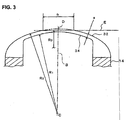
Figure 3 is an enlarged cross-sectional view of a part of an outer cutter used in the shaver ofFigure 1 ; -
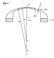
Figure 4 is an enlarged cross-sectional view of a part of an outer cutter used in another embodiment of the present invention; and -
Figure 5 shows the arrangement of outer cutters employed in the present invention. - In
Figure 1 , thereference numeral 10 is a shaver main body, and 12 is a cutter head openably or detachably attached to the upper portion of the shavermain body 10. Threecutter units 18 each consisting of anouter cutter 14 and aninner cutter 16 and so forth are installed in thecutter head 12. Threeouter cutters 14 of the threecutter units 18 are positioned with their centers at vertices of an equilateral triangle. - The
cutter head 12 has anouter cutter frame 20 that is openable or detachable upward relative to the shavermain body 10. Theouter cutters 14 are installed in three outer cutter installation holes formed in theouter cutter frame 20 in theouter cutter frame 20. Thecutter unit 18 that includes theouter cutter 14 is urged upward or in the direction such that theouter cutter 14 projects upward. - The
outer cutter 14 is made of metal in which a metal plate is formed into a substantially disk shape (seeFigure 2 ). Arecess 22 that is circular in plan view is formed in the center of the upper surface of theouter cutter 14, and acircular aperture 24 is formed in the center of therecess 22. The central tip of theinner cutter 16, which will be described later, is inserted into thisaperture 24 of theouter cutter 14, preventing axial vibration of theinner cutter 16. Acap 26 is fixed in therecess 22 of theouter cutter 14 from above. - A ring-shaped
thin layer portion 28 that bulges upward and that is concentric (when seen from above) with the center axis line A is formed in the upper surface of theouter cutter 14 so that the ring-shapedthin layer portion 28 surrounds therecess 22 and thecap 26. The upper surface of thethin layer portion 28 make the shaving surface, and its lower surface is an inner cutter running groove 34 (described below). In reality, thethin layer portion 28 is extremely thin, but it is shown thick in the drawing for ease of understanding. - As seen from
Figure 1 , a plurality ofslits 30, which transect thethin layer portion 28 from the center axis line A in substantially the radial direction, are formed in theouter cutter 14. More specifically, theslits 30 are formed along straight lines at a constant angular inclination relative to the radial straight line passing through the center axis line A inFigure 2 . Though theslits 30 are thus straight, they can be curved as shown inFigure 1 . The lower surface of arib 32, which remains betweenadjacent slits 30, works together with theinner cutter 16 and forms a cutter that cuts the hair. - The radial and vertical cross section described below is, to be precise, a vertical cross section in a direction of the
slit 30, but it may also be those that include a vertical cross section along theslit 30; no particular distinction is made here. - The upper and lower surfaces of the
rib 32 of theouter cutter 14, in a radial and vertical cross-sectional view (Figure 3 ) centered on the center axis line A, are formed in an arc-shaped curved surface centered on a curvature radius center (center of curvature) C, which is located on a perpendicular line B parallel to the center axis line A and passing through the center of thethin layer portion 28, i.e. the apex. More specifically, if R1 is the curvature radius of the lower surface of therib 32, the curvature radius R2 of the upper surface of therib 32 is set so that R2 = R1 + a, where a is the thickness of therib 32. - Furthermore, a predetermined (lateral or horizontal) range of a width b of the upper surface of the
rib 32 that includes the apex D is formed flat by removing (cutting out) an top portion of therib 32 according to a plane E that is orthogonal to the center axis line A (Figure 2 ). The upper surface is thus flat at this predetermined range b, and the curvature radius R3 is infinitely large. - The lower surface of the
thin layer portion 28 of the outer cutter 14 (in other words, the lower surface of the rib 32) is the inner cutter running groove (ring-shaped track) 34. Seen from below, the inner surface (bottom surface) of the innercutter running groove 34 takes a curved surface with curvature radius R1. - The
inner cutter 16 is comprised of a resin-madeboss element 36 that opens downward and a plurality ofcutter bodies 38 surrounding theboss element 36 and equidistantly fixed circumferentially. The plurality ofcutter bodies 38 can be formed so as to be connected to form a ring shape. The upper portion of thecutter body 38 makes sliding contact from below with the inner cutter running groove (track) 34 of theouter cutter 14. Furthermore, the upper edges of thecutter bodies 38 form cutting blades that are grinded to a curved surface with curvature radius R1, the same curvature as the lower surface of therib 32. Furthermore, as seen fromFigure 2 , the width W in the radial direction of thecutter body 38 is positioned within thethin layer portion 28 of theouter cutter 14. In other words, the width b of the flat surface portion of the outer cutter can formed smaller than the width W of thecutter body 38 of the inner cutter, thus being b < W. - An
engagement hole 40 that opens downward and that has a quadrilateral shape when seen in plan view is formed in theboss element 36, and adrive shaft 42 that projects from the shavermain body 10 engages theengagement hole 40. A quadrilateralspherical engagement head 44 is formed at the upper end of thedrive shaft 42 so as to enter theengagement hole 40 of theboss element 36 from below. Thedrive shaft 42 is rotationally driven by a motor (not shown in the drawing) housed inside the shavermain body 10 and rotates theinner cutter 16. - The
drive shaft 42 has a property of reciprocating along the center axis line A and urged in the upward projecting direction, and presses theinner cutter 16 upward or against theouter cutter 14. Therefore, thecutter bodies 38 of theinner cutter 16 elastically press the innercutter running groove 34 of theouter cutter 14 from below. - Furthermore, a
flange 46 is formed along the lower periphery of theouter cutter 14 so as to projects radially outward. Theflange 46 of theouter cutter 14 engages inside the outer cutter installation hole (not shown in the drawing) formed in theouter cutter frame 20 from below. Accordingly, thecutter unit 18 that is comprised of theouter cutter 14 and theinner cutter 16 can sink downward relative to theouter cutter frame 20 with elasticity. - According to the structure described above, the upper surface of the
outer cutter 14 opposite the inner cutter running groove (track) 34--more specifically, the upper surface of the rib 32-has such a shape that a predetermined range b that includes the apex is obtained by cutting out at plane E that is orthogonal to the center axis line A, so that the height of the upper surface changes smoothly. Therefore, thethin layer portion 28 is thinnest at the apex D and gradually becomes thicker as distance from the apex D increases away from the apex D. Accordingly, when the skin presses and touches perpendicular to the shaving surface of theouter cutter 14, it touches the shaving surface of theouter cutter 14 uniformly, and the pressing force can be averaged; and as a result, it is possible to shave the hair consistently and smoothly across a wide area. - Furthermore, since it is thinnest near the apex D and gradually becomes thicker as the distance increases away from the apex D in the radial direction from the apex D, when the skin is perpendicular to the
outer cutter 14 and presses and touches theouter cutter 14, it is possible to shave hair deeply with appropriate depth near the center. - When the outer cutter 14 (or the shaver) is moved parallel to the skin, the skin firmly touches the outer peripheral portion or the inner peripheral portion of the
outer cutter 14. In this case, since theouter cutter 14 is thick near the outer and inner periphery portions, overly deep shaving is prevented. - When the skin firmly presses the peripheral portions of the
outer cutter 14, hair easily enters theslits 30; and by moving the outer cutter 14 (or the shaver) with the hair entered in theslits 30, hair is guided by theslit 30 and moves radially near the center and shaved with appropriate depth at the thin predetermined range b. - Furthermore, as seen from
Figure 2 , thecutter body 38 of the inner cutter 16 (thecutter body 38 having the width W) is located within thethin layer portion 28 of the outer cutter 14 (b < W), both side ends of thecutter body 38 are within the thick region of the outer cutter, and there is no risk that both ends of thecutter body 38 damage the skin. - In the above-described structure, the upper surface of the
outer cutter 14 opposite the inner cutter running groove (track) 34 (more specifically, the upper surface of the rib 32) -is formed flat for the predetermined range b that includes the apex and the plane E that is orthogonal to the center axis line A. However, the flat portion can be formed flat on a plane that is not orthogonal (or not at right angles) to the center axis line A. In this slanted flat portion structure, the predetermined width b portion becomes substantially a ring shape in plan view whose width varies in the circumferential direction; and since the radial direction range where the thin layer portion is thin varies in the circumferential direction, the shaving feeling can vary by changing the angle of the circumferential direction of the outer cutter. -
Figure 4 shows another embodiment of the present invention. - In the
outer cutter 14 shown inFigure 4 , the curvature radius R2 of the upper surface of therib 32A of theouter cutter 14A is made sufficiently large with respect to the curvature radius R1 of the lower surface, and the center of curvature C2 of the upper surface is farther away from theouter cutter 14A on a straight line B than the center of curvature C1 of the lower surface. In other words, R2 > R1 + a, where a is the thickness of therib 32A. - In the structure of
Figure 4 , therib 32A is thinnest near apex D of the imaginary curved surface (see the double-dot broken line) centered on C1, and its thickness increases continuously with the increase in the radial distance from here. Accordingly, the same effect as in the structure shown inFigure 3 is achieved. In particular, in the structure ofFigure 4 , the curvature of the upper surface of therib 32A is constant and smooth, thus achieving the effect that the shaving feeling is even smoother than that of the structure ofFigure 3 . -
Figure 5 shows the arrangement of theouter cutters 14B in accordance with the present invention. - The
outer cutters 14B are arranged with their centers A in an equilateral triangle in plan view. Furthermore, in eachouter cutter 14B the portion inside the triangle AAA (the shaded portion) has the structure described above inFigure 3 orFigure 4 , and the portion outside the triangle AAA has a structure in which the thickness of the thin layer portion is constant. More specifically, the shaded portion of an arc or sector shape of each one of the outer cutters is thin in the predetermined range near the apex, and the area outside the shaded portion of each outer cutter has a thickness that is substantially the same as that of the inner and outer peripheral areas of the shaded portion and that is sufficiently thick and constant. - With the arrangement shown in
Figure 5 , even if the skin wrinkles at a part of each outer cutter that face the outer peripheral side of the outer cutter frame because of the outer edge of theouter cutter 14B when theouter cutter 14B (or the shaver) is moved, the skin has difficulty reaching thecutter body 38 and there is no risk that the skin is damaged, because theouter cutter 14B has a constant, large thickness on the outer peripheral side of the outer cutter frame. Furthermore, if the skin is pressed near the center of the triangle AAA, since theouter cutter 14B in this region is thin near the apex, it is possible to shave smoothly and with sufficient depth with a light pressing force. It is thus possible in the present invention to combine the inconsistent thickness structure ofFigure 3 or4 and the constant thickness structure in view of the wrinkle occurrence status and the like.
Claims (6)
- A rotary type electric shaver comprising an outer cutter frame (20) that is provided on a shaver main body (10), an outer cutter (14, 14A, 14B) that is installed in said outer cutter frame (20) and has a shaving surface on an upper surface of a ring-shaped thin layer portion (28) thereof (with the outer cutter (14, 14A, 14B) seen in upright position), and an inner cutter (16) that is driven rotationally and has a cutter body (38) which makes sliding contact from below with a lower surface of said thin layer portion of said outer cutter (14, 14A, 14B), wherein
said thin layer portion (28) has a substantially arc shape with the upper surface that is at least partly convex upward in radial and vertical cross section that includes a center axis line (A) which is a rotational center of said inner cutter (16),
characterized in that
a thickness of said thin layer portion (28) is smallest at an apex (D) of said convex arc shape and gradually becomes larger as a distance from said apex (D) increases
said shaving surface of said outer cutter (14) is formed therein with a flat surface portion (b) and
said flat surface in said shaving surface of said thin layer portion (28) of said outer cutter (14) is smaller in width than said cutter body (38) of said inner cutter (16) which makes sliding contact with said lower surface of said thin layer portion (28). - The rotary type electric shaver according to Claim 1, wherein
a center of curvature (C2) for an apex area of said shaving surface is located farther from an apex (D) of said shaving surface than a center of curvature (C1) of a lower surface of said thin layer portion (28), and
said centers of curvature (C1, C2) are both positioned on a straight line (B) that passes through said apex (D) of said shaving surface and is parallel to said center axis line (A). - The rotary type electric shaver according to Claim 1, wherein said flat surface portion (b) is substantially orthogonal to said center axis line (A).
- The rotary type electric shaver according to Claim 1, wherein said shaving surface of said outer cutter (14) is formed therein with a flat surface portion (b) that is not orthogonal to said center axis line (A).
- The rotary type electric shaver according to Claim 2, wherein a plurality of said outer cutter (14B) and inner cutter (16) are provided, and a part of said shaving surface of each one of said outer cutters (14B) takes a sector shape on a center side of said outer cutter frame (20).
- The rotary type electric shaver according to Claim 3, wherein said outer cutter (14B) and inner cutter (16) are provided in a plurality of numbers, and a part of said flat shaving surface of each one of said outer cutters (14B) takes a sector shape on a center side of said outer cutter frame (20).
Applications Claiming Priority (1)
| Application Number | Priority Date | Filing Date | Title |
|---|---|---|---|
| JP2005038109A JP2006223373A (en) | 2005-02-15 | 2005-02-15 | Rotary electric shaver |
Publications (2)
| Publication Number | Publication Date |
|---|---|
| EP1690656A1 EP1690656A1 (en) | 2006-08-16 |
| EP1690656B1 true EP1690656B1 (en) | 2010-10-13 |
Family
ID=36569922
Family Applications (1)
| Application Number | Title | Priority Date | Filing Date |
|---|---|---|---|
| EP06002820A Expired - Fee Related EP1690656B1 (en) | 2005-02-15 | 2006-02-13 | Rotary type electric shaver |
Country Status (6)
| Country | Link |
|---|---|
| US (1) | US7743507B2 (en) |
| EP (1) | EP1690656B1 (en) |
| JP (1) | JP2006223373A (en) |
| CN (1) | CN100441382C (en) |
| CA (1) | CA2536424A1 (en) |
| DE (1) | DE602006017453D1 (en) |
Families Citing this family (11)
| Publication number | Priority date | Publication date | Assignee | Title |
|---|---|---|---|---|
| EP1927441A1 (en) * | 2006-11-28 | 2008-06-04 | Koninklijke Philips Electronics N.V. | Cap having a comfort profile, which is intended to be applied in a shaving head of a shaving apparatus |
| KR200455792Y1 (en) * | 2008-12-17 | 2011-09-27 | 오태준 | A blade assembly of electric razor |
| US9027251B2 (en) | 2009-04-29 | 2015-05-12 | Spectrum Brands, Inc. | Rotary electric shaver |
| EP2747959B1 (en) | 2011-12-19 | 2015-12-09 | Koninklijke Philips N.V. | Improved shaving head with doming control |
| EP2802437B1 (en) | 2012-01-10 | 2016-11-02 | Koninklijke Philips N.V. | Rotary shaving unit |
| CN203171675U (en) * | 2013-01-24 | 2013-09-04 | 黄勇辉 | Eccentric or inclined eccentric shaver fixed cutter |
| CN104400799A (en) * | 2014-11-27 | 2015-03-11 | 海宁市新艺机电有限公司 | Rotary shaving head assembly of electric shaver |
| US20170217030A1 (en) * | 2016-02-02 | 2017-08-03 | Izumi Products Company | Rotary electric shaver and method of manufacturing outer blade of rotary electric shaver |
| EP3643461A1 (en) * | 2018-10-23 | 2020-04-29 | Koninklijke Philips N.V. | Hand-held appliance with improved coupling structure for a functional attachment of the appliance |
| EP3659759A1 (en) * | 2018-11-28 | 2020-06-03 | Koninklijke Philips N.V. | Hair-cutting unit with cutter blocking prevention |
| EP3753690A1 (en) * | 2019-06-21 | 2020-12-23 | Koninklijke Philips N.V. | Guard element for use in a hair-cutting unit |
Citations (2)
| Publication number | Priority date | Publication date | Assignee | Title |
|---|---|---|---|---|
| US3526959A (en) * | 1967-11-07 | 1970-09-08 | Wilkinson Sword Ltd | Dry shavers |
| US6085421A (en) * | 1998-03-27 | 2000-07-11 | U.S. Philips Corporation | Shaving apparatus |
Family Cites Families (11)
| Publication number | Priority date | Publication date | Assignee | Title |
|---|---|---|---|---|
| US2245420A (en) * | 1939-03-20 | 1941-06-10 | Chris L Volz | Cutter head for electric razors |
| CH290390A (en) * | 1948-12-06 | 1953-04-30 | Konrad Hermann | Mechanical razor. |
| JPS6237560Y2 (en) * | 1979-02-20 | 1987-09-25 | ||
| JPS62123772U (en) * | 1986-01-27 | 1987-08-06 | ||
| BE1007711A3 (en) * | 1993-11-05 | 1995-10-03 | Koninkl Philips Electronics Nv | Shaver. |
| EP0705158B1 (en) * | 1994-04-26 | 1998-08-19 | Koninklijke Philips Electronics N.V. | Shaving apparatus |
| JPH114980A (en) * | 1997-06-17 | 1999-01-12 | Izumi Prod Co | Electric shaver |
| US6769179B2 (en) * | 2000-07-06 | 2004-08-03 | Teizoh Satoh | Shaver |
| US20030070304A1 (en) * | 2001-10-15 | 2003-04-17 | Zachary Curello | Cutting foil for rotary shavers and manufacturing methods for producing same |
| AU2002366972A1 (en) * | 2002-01-16 | 2003-07-30 | Koninklijke Philips Electronics N.V. | Shaving head with rotary cutter, and shaving apparatus comprising such a shaving head |
| JP2006198093A (en) * | 2005-01-19 | 2006-08-03 | Izumi Products Co | Rotary electric shaver |
-
2005
- 2005-02-15 JP JP2005038109A patent/JP2006223373A/en active Pending
-
2006
- 2006-02-13 DE DE602006017453T patent/DE602006017453D1/en active Active
- 2006-02-13 CA CA002536424A patent/CA2536424A1/en not_active Abandoned
- 2006-02-13 EP EP06002820A patent/EP1690656B1/en not_active Expired - Fee Related
- 2006-02-14 US US11/353,669 patent/US7743507B2/en not_active Expired - Fee Related
- 2006-02-15 CN CNB2006100047022A patent/CN100441382C/en not_active Expired - Fee Related
Patent Citations (2)
| Publication number | Priority date | Publication date | Assignee | Title |
|---|---|---|---|---|
| US3526959A (en) * | 1967-11-07 | 1970-09-08 | Wilkinson Sword Ltd | Dry shavers |
| US6085421A (en) * | 1998-03-27 | 2000-07-11 | U.S. Philips Corporation | Shaving apparatus |
Also Published As
| Publication number | Publication date |
|---|---|
| CN1820909A (en) | 2006-08-23 |
| EP1690656A1 (en) | 2006-08-16 |
| US7743507B2 (en) | 2010-06-29 |
| JP2006223373A (en) | 2006-08-31 |
| US20060179658A1 (en) | 2006-08-17 |
| CN100441382C (en) | 2008-12-10 |
| CA2536424A1 (en) | 2006-08-15 |
| DE602006017453D1 (en) | 2010-11-25 |
Similar Documents
| Publication | Publication Date | Title |
|---|---|---|
| EP1690656B1 (en) | Rotary type electric shaver | |
| EP1683609B1 (en) | Rotary type electric shaver | |
| US7540090B2 (en) | Rotary type electric shaver | |
| US20060179659A1 (en) | Rotary type electric shaver | |
| US20230150157A1 (en) | Rotary electric shaver | |
| EP1902818B1 (en) | Rotary electric shaver | |
| EP0566234B1 (en) | Electric razor | |
| CN1079719C (en) | Electric shaver | |
| JP2007319339A (en) | Rotary type electric shaver | |
| JP4338422B2 (en) | Inner blade unit of rotary electric razor | |
| JP2006218218A (en) | Rotary type electric razor | |
| US7065878B2 (en) | Rotary type electric shaver | |
| KR200387681Y1 (en) | Rotating blade of electric razor | |
| CN210282387U (en) | Rotary electric shaving device | |
| JPS5935179Y2 (en) | rotary electric razor blade | |
| MXPA98004823A (en) | Electric shave machine |
Legal Events
| Date | Code | Title | Description |
|---|---|---|---|
| PUAI | Public reference made under article 153(3) epc to a published international application that has entered the european phase |
Free format text: ORIGINAL CODE: 0009012 |
|
| 17P | Request for examination filed |
Effective date: 20060221 |
|
| AK | Designated contracting states |
Kind code of ref document: A1 Designated state(s): AT BE BG CH CY CZ DE DK EE ES FI FR GB GR HU IE IS IT LI LT LU LV MC NL PL PT RO SE SI SK TR |
|
| AX | Request for extension of the european patent |
Extension state: AL BA HR MK YU |
|
| AKX | Designation fees paid |
Designated state(s): DE FR GB IT NL |
|
| 17Q | First examination report despatched |
Effective date: 20070404 |
|
| R17C | First examination report despatched (corrected) |
Effective date: 20070709 |
|
| GRAP | Despatch of communication of intention to grant a patent |
Free format text: ORIGINAL CODE: EPIDOSNIGR1 |
|
| GRAS | Grant fee paid |
Free format text: ORIGINAL CODE: EPIDOSNIGR3 |
|
| GRAA | (expected) grant |
Free format text: ORIGINAL CODE: 0009210 |
|
| AK | Designated contracting states |
Kind code of ref document: B1 Designated state(s): DE FR GB IT NL |
|
| REG | Reference to a national code |
Ref country code: GB Ref legal event code: FG4D |
|
| REG | Reference to a national code |
Ref country code: NL Ref legal event code: T3 |
|
| REF | Corresponds to: |
Ref document number: 602006017453 Country of ref document: DE Date of ref document: 20101125 Kind code of ref document: P |
|
| PLBE | No opposition filed within time limit |
Free format text: ORIGINAL CODE: 0009261 |
|
| STAA | Information on the status of an ep patent application or granted ep patent |
Free format text: STATUS: NO OPPOSITION FILED WITHIN TIME LIMIT |
|
| 26N | No opposition filed |
Effective date: 20110714 |
|
| REG | Reference to a national code |
Ref country code: DE Ref legal event code: R097 Ref document number: 602006017453 Country of ref document: DE Effective date: 20110714 |
|
| PGFP | Annual fee paid to national office [announced via postgrant information from national office to epo] |
Ref country code: IT Payment date: 20120222 Year of fee payment: 7 |
|
| PGFP | Annual fee paid to national office [announced via postgrant information from national office to epo] |
Ref country code: NL Payment date: 20120229 Year of fee payment: 7 |
|
| REG | Reference to a national code |
Ref country code: NL Ref legal event code: V1 Effective date: 20130901 |
|
| PG25 | Lapsed in a contracting state [announced via postgrant information from national office to epo] |
Ref country code: NL Free format text: LAPSE BECAUSE OF NON-PAYMENT OF DUE FEES Effective date: 20130901 |
|
| PG25 | Lapsed in a contracting state [announced via postgrant information from national office to epo] |
Ref country code: IT Free format text: LAPSE BECAUSE OF NON-PAYMENT OF DUE FEES Effective date: 20130213 |
|
| REG | Reference to a national code |
Ref country code: FR Ref legal event code: PLFP Year of fee payment: 11 |
|
| REG | Reference to a national code |
Ref country code: FR Ref legal event code: PLFP Year of fee payment: 12 |
|
| REG | Reference to a national code |
Ref country code: FR Ref legal event code: PLFP Year of fee payment: 13 |
|
| REG | Reference to a national code |
Ref country code: DE Ref legal event code: R082 Ref document number: 602006017453 Country of ref document: DE Representative=s name: PATENTANWALTSKANZLEI HINKELMANN, DE |
|
| PGFP | Annual fee paid to national office [announced via postgrant information from national office to epo] |
Ref country code: GB Payment date: 20190218 Year of fee payment: 14 Ref country code: DE Payment date: 20190219 Year of fee payment: 14 |
|
| PGFP | Annual fee paid to national office [announced via postgrant information from national office to epo] |
Ref country code: FR Payment date: 20190218 Year of fee payment: 14 |
|
| REG | Reference to a national code |
Ref country code: DE Ref legal event code: R119 Ref document number: 602006017453 Country of ref document: DE |
|
| GBPC | Gb: european patent ceased through non-payment of renewal fee |
Effective date: 20200213 |
|
| PG25 | Lapsed in a contracting state [announced via postgrant information from national office to epo] |
Ref country code: FR Free format text: LAPSE BECAUSE OF NON-PAYMENT OF DUE FEES Effective date: 20200229 Ref country code: DE Free format text: LAPSE BECAUSE OF NON-PAYMENT OF DUE FEES Effective date: 20200901 Ref country code: GB Free format text: LAPSE BECAUSE OF NON-PAYMENT OF DUE FEES Effective date: 20200213 |