EP1689620B1 - Instrument panel system with hidden airbag door - Google Patents
Instrument panel system with hidden airbag door Download PDFInfo
- Publication number
- EP1689620B1 EP1689620B1 EP04819049A EP04819049A EP1689620B1 EP 1689620 B1 EP1689620 B1 EP 1689620B1 EP 04819049 A EP04819049 A EP 04819049A EP 04819049 A EP04819049 A EP 04819049A EP 1689620 B1 EP1689620 B1 EP 1689620B1
- Authority
- EP
- European Patent Office
- Prior art keywords
- tear seam
- instrument panel
- door portion
- door
- notch
- Prior art date
- Legal status (The legal status is an assumption and is not a legal conclusion. Google has not performed a legal analysis and makes no representation as to the accuracy of the status listed.)
- Expired - Lifetime
Links
Images

Classifications
-
- B—PERFORMING OPERATIONS; TRANSPORTING
- B60—VEHICLES IN GENERAL
- B60R—VEHICLES, VEHICLE FITTINGS, OR VEHICLE PARTS, NOT OTHERWISE PROVIDED FOR
- B60R21/00—Arrangements or fittings on vehicles for protecting or preventing injuries to occupants or pedestrians in case of accidents or other traffic risks
- B60R21/02—Occupant safety arrangements or fittings, e.g. crash pads
- B60R21/16—Inflatable occupant restraints or confinements designed to inflate upon impact or impending impact, e.g. air bags
- B60R21/20—Arrangements for storing inflatable members in their non-use or deflated condition; Arrangement or mounting of air bag modules or components
- B60R21/215—Arrangements for storing inflatable members in their non-use or deflated condition; Arrangement or mounting of air bag modules or components characterised by the covers for the inflatable member
- B60R21/2165—Arrangements for storing inflatable members in their non-use or deflated condition; Arrangement or mounting of air bag modules or components characterised by the covers for the inflatable member characterised by a tear line for defining a deployment opening
-
- B—PERFORMING OPERATIONS; TRANSPORTING
- B60—VEHICLES IN GENERAL
- B60R—VEHICLES, VEHICLE FITTINGS, OR VEHICLE PARTS, NOT OTHERWISE PROVIDED FOR
- B60R21/00—Arrangements or fittings on vehicles for protecting or preventing injuries to occupants or pedestrians in case of accidents or other traffic risks
- B60R21/02—Occupant safety arrangements or fittings, e.g. crash pads
- B60R21/16—Inflatable occupant restraints or confinements designed to inflate upon impact or impending impact, e.g. air bags
- B60R21/20—Arrangements for storing inflatable members in their non-use or deflated condition; Arrangement or mounting of air bag modules or components
- B60R21/215—Arrangements for storing inflatable members in their non-use or deflated condition; Arrangement or mounting of air bag modules or components characterised by the covers for the inflatable member
- B60R21/2165—Arrangements for storing inflatable members in their non-use or deflated condition; Arrangement or mounting of air bag modules or components characterised by the covers for the inflatable member characterised by a tear line for defining a deployment opening
- B60R21/21656—Steering wheel covers or similar cup-shaped covers
-
- B—PERFORMING OPERATIONS; TRANSPORTING
- B60—VEHICLES IN GENERAL
- B60R—VEHICLES, VEHICLE FITTINGS, OR VEHICLE PARTS, NOT OTHERWISE PROVIDED FOR
- B60R21/00—Arrangements or fittings on vehicles for protecting or preventing injuries to occupants or pedestrians in case of accidents or other traffic risks
- B60R21/02—Occupant safety arrangements or fittings, e.g. crash pads
- B60R21/16—Inflatable occupant restraints or confinements designed to inflate upon impact or impending impact, e.g. air bags
- B60R21/20—Arrangements for storing inflatable members in their non-use or deflated condition; Arrangement or mounting of air bag modules or components
- B60R21/205—Arrangements for storing inflatable members in their non-use or deflated condition; Arrangement or mounting of air bag modules or components in dashboards
-
- B—PERFORMING OPERATIONS; TRANSPORTING
- B62—LAND VEHICLES FOR TRAVELLING OTHERWISE THAN ON RAILS
- B62D—MOTOR VEHICLES; TRAILERS
- B62D25/00—Superstructure or monocoque structure sub-units; Parts or details thereof not otherwise provided for
- B62D25/08—Front or rear portions
- B62D25/14—Dashboards as superstructure sub-units
-
- B—PERFORMING OPERATIONS; TRANSPORTING
- B60—VEHICLES IN GENERAL
- B60R—VEHICLES, VEHICLE FITTINGS, OR VEHICLE PARTS, NOT OTHERWISE PROVIDED FOR
- B60R11/00—Arrangements for holding or mounting articles, not otherwise provided for
- B60R2011/0001—Arrangements for holding or mounting articles, not otherwise provided for characterised by position
- B60R2011/0003—Arrangements for holding or mounting articles, not otherwise provided for characterised by position inside the vehicle
- B60R2011/0005—Dashboard
Definitions
- This invention relates generally to instrument panel assemblies, and more particularly to an instrument panel having a hidden airbag door.
- Known instrument panel assemblies include a beam structure and at least one decorative instrument panel attached to the beam structure. Some of the decorative panels act as knee bolsters to protect the knees of vehicle occupants in the event of an impact.
- An instrument panel assembly is mounted inside the passenger compartment of an automobile with the beam structure attached to the automobile body, typically to the A-pillar.
- Known instrument panel beam structures are fabricated from steel or plastic.
- the instrument panel assembly includes an airbag opening covered by an airbag door.
- HVAC heating, ventilating, and air conditioning
- the airbag forces the door open to permit the airbag to exit through the opening in the instrument panel.
- a known instrument panel having a hidden airbag door includes a molded base substrate that is either covered with a semi-rigid foam and a cover material, painted, or left unpainted.
- the underside of the instrument panel base substrate is scored with a laser to create a deployment seam in the shape of a door.
- a separate metal hinge assembly is molded into the back of the door and the underside of the base substrate to permit the door to pivot open during airbag deployment. The force of the airbag deployment forces the deployment seam to separate permitting the door to be forced open. If required, the door is also forced through the surface foam layer and the cover layer of the instrument panel so the airbag can exit the instrument panel. The layer and the cover layer of the instrument panel so the airbag can exit the instrument panel.
- the underside of the cover layer has either a seam that is moulded in, or is laser scored to facilitate the door breaking through the cover.
- WO 03/035435 A discloses an instrument panel comprising a thermoplastic base substrate having a first surface and an opposing second surface; a door portion defined by a tear seam notch in at least one of said first and second surface of said base substrate, said tear seam notch defining a periphery of said door portion; and at least one hinge portion.
- an instrument panel is as defined by claim 1 provided.
- the instrument panel includes a thermoplastic base substrate having a first surface and an opposing second surface, and a door portion defined by a tear seam notch in the first surface of the base substrate.
- the tear seam notch defines a periphery of the door portion.
- the instrument panel also includes at least one hinge portion defined by a plurality of tear seam notches in the first surface of the base substrate. Each hinge portion interrupts the door portion tear seam notch so that the door portion tear seam notch is not continuous.
- an instrument panel system as defined by claim 8 includes an instrument panel and an airbag.
- the air bag is positioned adjacent the instrument panel.
- the instrument panel includes a thermoplastic base substrate having a first surface and an opposing second surface, and a door portion defined by a tear seam notch In the first surface of the base substrate.
- the tear seam notch defines a periphery of the door portion.
- the instrument panel also includes at least one hinge portion defined by a plurality of tear seam notches in the first surface of the base substrate. Each hinge portion interrupts the door portion tear seam notch so that the door portion tear seam notch is not continuous.
- the airbag door is not visible to vehicle occupants before deployment of the airbag.
- the hidden airbag door is self-hinging and opens by the force of the airbag deploying and permits the airbag to exit the instrument panel and enter the passenger compartment.
- the opened airbag door includes smooth surfaces without sharp and/or hard edges to avoid vehicle occupant injuries.
- Figure 1 is an exploded perspective view of an instrument panel assembly 10 in accordance with an exemplary embodiment of the present invention.
- Instrument panel assembly 10 includes an instrument panel 12 having duct outlet openings 14, 16, 18, and 20. Vent grills 22, 24, 26, and 28 are sized to mate with openings 14, 16, 18, and 20 respectively.
- An instrument cluster 30 and a cluster trim plate 32 are coupled to instrument panel 12.
- Cluster trim plate 32 includes vent grills 34 and 36.
- a driver side knee bolster 38 and a glove box surround 40 are coupled to instrument panel 12.
- a glove box 42 attaches to a glove box hinge portion 44 of glove box surround 40.
- the combination of glove box surround 40 and glove box 42 act as a passenger knee bolster.
- a center bezel 46 is coupled to driver side knee bolster 38 and glove box surround 40.
- a fuse access door 48 covers a fuse access opening 50 in glove box surround 40.
- An airbag module 52 is mounted adjacent instrument panel 12.
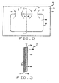
- FIG. 2 is a bottom schematic view of a portion of instrument panel 12, and Figure 3 is a cross sectional view of instrument panel 12 through line C-C.
- a base substrate 54 includes an upper surface 56 and a lower surface 58.
- upper surface 56 faces the passenger compartment and lower surface 58 faces the inside of instrument panel assembly 10.
- Base substrate 54 includes a tear seam notch 60 that defines the outer periphery of an airbag door 62.
- tear seam notch 60 is located in lower surface 58 of base substrate 54.
- tear seam notch 60 is located in upper surface 56 of base substrate 54.
- At least one hinge portion 64 (two shown) is defined by hinge tear seam notches 66 in base substrate 54.
- Each hinge portion 64 is located so that it interrupts airbag door tear seam notch 60.
- tear seam notch 60 is non-continuous in the area of each hinge portion 64 creating a self-hinging airbag door.
- Hinge portion tear seam notches 66 are substantially orthogonal to airbag door tear seam notch 60.
- hinge portion tear seam notches 66 extend from a location in airbag door 62 to a location away from airbag door 62.
- hinge portion tear seam notches 66 extend from airbag door tear seam notch 60 to a location away from air bag door 62.
- hinge portion tear seam notches 66 extend from a location in airbag door 62 to airbag door tear seam notch 60.
- Hinge tear seam notches 66 are curved with a relatively small radius of curvature to prevent ripping of base substrate 54 adjacent hinge tear seam notches 66.
- the tear seam notches 66 that form each hinge portion 64 are arranged so that the width of hinge portion 64 is smallest at the intersection with airbag door tear seam notch 60.
- Hinge portions 64 have a thickness that is substantially equivalent to the thickness of airbag door 62 and instrument panel 12. Hinge portions 64 connect airbag door 62 to instrument panel 12 during and after an airbag deployment event which permits airbag door 62 to open allowing airbag 52 to fully inflate through instrument panel 12.
- Tear seam notches 60 and 66 can be formed in base substrate 54 by any suitable method.
- Some suitable methods for forming tear seam notches 60 and 66 include, but are not limited to, press molding tear seam notches 60 and 66 into base substrate 54, forming tear seam notches 60 and 66 during the injection molding of base substrate 54, laser scribing tear seam notches 60 and 66 into base substrate 54, scribing tear seam notches 60 and 66 into base substrate 54 with a high pressure water stream, and scribing tear seam notches 60 and 66 into base substrate 54 with a hot knife tool.
- a cross-section of tear seam notches 60 and 66 can have any suitable shape, for example, a V-shape, a U-shape, a conical-shape, a spherical-shape, or a box shape.
- Base substrate 54 should be flexible at temperatures of about 100°C to about -40°C.
- Base substrate 54 can be extruded or molded from one of many thermoplastic materials.
- thermoplastic materials include, but are not limited to, acrylonitrile-butadiene-styrene (ABS), polycarbonate (LEXAN® and LEXAN® EXL resins commercially available from General Electric Company), polycarbonate/ABS blend, a copolycarbonate-polyester, acrylic-styrene-acrylonitrile (ASA), acrylonitrile-(ethylene-polypropylene diamine modified)-styrene (AES), phenylene ether resins, glass filled blends of polyphenylene oxide and polystyrene, blends of polyphenylene ether/polyamide (NORYL GTX® resins from General Electric Company), blends of polycarbonate/PET/PBT, polybutylene terephthalate and impact modifier (XENOY® resins commercially available from General Electric Company), polyamides, phenylene sulfide resins, polyvinyl chloride PVC, high impact polystyrene (HIPS), low
- instrument panel 12 includes an intermediate layer 70 on upper surface 56 of base substrate 54 and a cover layer 72 on upper surface 74 of intermediate layer 70.
- instrument panel 12 does not have any additional layers on upper surface 56 of base substrate 54.
- upper surface 56 of base substrate 54 is be painted.
- Intermediate layer 70 is formed from a resilient material, for example, a foam material. The resilient material provides protection to vehicle occupants in impact events.
- Cover layer 72 is formed from any suitable decorative material, for example, a thermoplastic material, leather, fabric, and the like. With the application of intermediate layer 70 and cover layer 72 to base substrate 54, airbag door 62 is not visible to a vehicle occupant.
- intermediate layer 70 and cover layer 72 do not contain tear seam scores or notches to aid the opening of airbag door 62.
- at least one of intermediate layer 70 and cover layer 72 also include tear seam notches.
- airbag 52 In operation, during an airbag deployment event, airbag 52 inflates and imparts a force on instrument panel 12. The force causes tear seam notches 60 and 66 to open and causes airbag door 62 to move to an open position by breaking through intermediate layer 70 and cover layer 72. With airbag door 62 and in an open position, airbag 52 can fully inflate through instrument panel 12. Open airbag door 62 has smooth surfaces without sharp/hard edges to avoid vehicle occupant injuries.
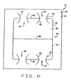
- FIG. 6 is a schematic illustration of a portion of instrument panel 12 in accordance with another exemplary embodiment of the present invention.
- An outer periphery of an airbag door 80 in instrument panel 12 is defined by a tear seam notch 82 located in lower surface 58 of base substrate 54.
- Air bag door 80 includes segments 84 and 86 and includes a segment tear seam notch 88 located between segments 84 and 86 and intersecting airbag door tear seam notch 82 at each end.
- the outer periphery of airbag door segments 84 and 86 are defined by airbag door tear seam notch 82 and segment tear seam notch 88.
- the exemplary embodiment shown in Figure 6 has two airbag door segments 84 and 86; however, in alternate embodiments air bag door 80 can have more than two door segments and more than one segment tear seam notch to define the door segments.
- At least one hinge portion 90 is defined by hinge tear seam notches 92 in base substrate 54. Each hinge portion 90 is located so that it interrupts airbag door tear seam notch 82. Particularly, tear seam notch 82 is non-continuous in the area of each hinge portion 90. Hinge portion tear seam notches 92 are substantially orthogonal to airbag door tear seam notch 82 and extend from a location in airbag door segment 84 or 86 to a location away from airbag door 80. Each door segment 84 and 86 are connected to instrument panel 12 by at least one hinge portion 90. In an alternate embodiment hinge portion tear seam notches 92 extend from airbag door tear seam notch 82 to a location away from air bag door segment 84 or 86.
- hinge portion tear seam notches 92 extend from a location in airbag door segment 84 or 86 to airbag door tear seam notch 82.
- Hinge tear seam notches 92 are curved with a relatively small radius of curvature to prevent ripping of base substrate 54 adjacent hinge tear seam notches 92.
- the tear seam notches 92 that form each hinge portion 90 are arranged so that the width of hinge portion 90 is smallest at the intersection with airbag door tear seam notch 82.
Landscapes
- Engineering & Computer Science (AREA)
- Mechanical Engineering (AREA)
- Chemical & Material Sciences (AREA)
- Combustion & Propulsion (AREA)
- Transportation (AREA)
- Air Bags (AREA)
- Instrument Panels (AREA)
Abstract
Description
- This invention relates generally to instrument panel assemblies, and more particularly to an instrument panel having a hidden airbag door.
- Known instrument panel assemblies include a beam structure and at least one decorative instrument panel attached to the beam structure. Some of the decorative panels act as knee bolsters to protect the knees of vehicle occupants in the event of an impact. An instrument panel assembly is mounted inside the passenger compartment of an automobile with the beam structure attached to the automobile body, typically to the A-pillar. Known instrument panel beam structures are fabricated from steel or plastic.
- A number of vehicle systems are housed within the instrument panel assembly, for example, the heating, ventilating, and air conditioning (HVAC) system, and the airbag system(s). To permit deployment of the airbag, the instrument panel includes an airbag opening covered by an airbag door. The placement of a door in the middle of a smooth surfaced instrument panel is considered as aesthetically unacceptable because the door destroys the clean aesthetic lines of an instrument panel. The deployment of the airbag forces the door open to permit the airbag to exit through the opening in the instrument panel.
- A known instrument panel having a hidden airbag door includes a molded base substrate that is either covered with a semi-rigid foam and a cover material, painted, or left unpainted. The underside of the instrument panel base substrate is scored with a laser to create a deployment seam in the shape of a door. A separate metal hinge assembly is molded into the back of the door and the underside of the base substrate to permit the door to pivot open during airbag deployment. The force of the airbag deployment forces the deployment seam to separate permitting the door to be forced open. If required, the door is also forced through the surface foam layer and the cover layer of the instrument panel so the airbag can exit the instrument panel. The layer and the cover layer of the instrument panel so the airbag can exit the instrument panel. The underside of the cover layer has either a seam that is moulded in, or is laser scored to facilitate the door breaking through the cover. The multiple components of the airbag door hinge increases complexity of fabrication and assembly which increases fabrication time and increases labour costs.
-
WO 03/035435 A - In one aspect, an instrument panel is as defined by claim 1 provided. The instrument panel includes a thermoplastic base substrate having a first surface and an opposing second surface, and a door portion defined by a tear seam notch in the first surface of the base substrate. The tear seam notch defines a periphery of the door portion. The instrument panel also includes at least one hinge portion defined by a plurality of tear seam notches in the first surface of the base substrate. Each hinge portion interrupts the door portion tear seam notch so that the door portion tear seam notch is not continuous.
- In another aspect, an instrument panel system as defined by
claim 8 is provided that includes an instrument panel and an airbag. The air bag is positioned adjacent the instrument panel. The instrument panel includes a thermoplastic base substrate having a first surface and an opposing second surface, and a door portion defined by a tear seam notch In the first surface of the base substrate. The tear seam notch defines a periphery of the door portion. The instrument panel also includes at least one hinge portion defined by a plurality of tear seam notches in the first surface of the base substrate. Each hinge portion interrupts the door portion tear seam notch so that the door portion tear seam notch is not continuous. -
-
Figure 1 is a perspective view of an instrument panel assembly in accordance with an embodiment of the present invention. - .
Figure 2 is a schematic illustration of a portion of the instrument panel shown inFigure 1 in accordance with an embodiment of the present invention. -
Figure 3 is a cross sectional view of the instrument panel through line C-C ofFigure 2 . -
Figure 4 is a schematic illustration of a portion of the instrument panel shown inFigure 1 in accordance with another embodiment of the present invention. -
Figure 5 is a schematic illustration of a portion of the instrument panel shown inFigure 1 in accordance with another embodiment of the present invention. -
Figure 6 is a schematic illustration of a portion of the instrument panel shown inFigure 1 in accordance with another embodiment of the present invention. - An instrument panel system that includes an instrument panel with a hidden airbag door is described below in more detail. The airbag door is not visible to vehicle occupants before deployment of the airbag. The hidden airbag door is self-hinging and opens by the force of the airbag deploying and permits the airbag to exit the instrument panel and enter the passenger compartment. The opened airbag door includes smooth surfaces without sharp and/or hard edges to avoid vehicle occupant injuries.
- Referring to the drawings,
Figure 1 is an exploded perspective view of aninstrument panel assembly 10 in accordance with an exemplary embodiment of the present invention.Instrument panel assembly 10 includes aninstrument panel 12 havingduct outlet openings Vent grills openings instrument cluster 30 and acluster trim plate 32 are coupled toinstrument panel 12.Cluster trim plate 32 includesvent grills side knee bolster 38 and aglove box surround 40 are coupled toinstrument panel 12. Aglove box 42 attaches to a glovebox hinge portion 44 ofglove box surround 40. The combination of glove box surround 40 andglove box 42 act as a passenger knee bolster. Acenter bezel 46 is coupled to driverside knee bolster 38 andglove box surround 40. Afuse access door 48 covers a fuse access opening 50 inglove box surround 40. Anairbag module 52 is mountedadjacent instrument panel 12. -
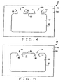
Figure 2 is a bottom schematic view of a portion ofinstrument panel 12, andFigure 3 is a cross sectional view ofinstrument panel 12 through line C-C. Referring toFigures 2 and 3 , abase substrate 54 includes anupper surface 56 and alower surface 58. Wheninstrument panel 12 is installed in a vehicle,upper surface 56 faces the passenger compartment andlower surface 58 faces the inside ofinstrument panel assembly 10.Base substrate 54 includes atear seam notch 60 that defines the outer periphery of anairbag door 62. In this exemplary embodiment,tear seam notch 60 is located inlower surface 58 ofbase substrate 54. In an alternate embodiment,tear seam notch 60 is located inupper surface 56 ofbase substrate 54. At least one hinge portion 64 (two shown) is defined by hingetear seam notches 66 inbase substrate 54. Eachhinge portion 64 is located so that it interrupts airbag doortear seam notch 60. Particularly,tear seam notch 60 is non-continuous in the area of eachhinge portion 64 creating a self-hinging airbag door. Hinge portiontear seam notches 66 are substantially orthogonal to airbag doortear seam notch 60. In the exemplary embodiment, hinge portiontear seam notches 66 extend from a location inairbag door 62 to a location away fromairbag door 62. In an alternate embodiment shown inFigure 4 , hinge portiontear seam notches 66 extend from airbag doortear seam notch 60 to a location away fromair bag door 62. In another alternate embodiment shown inFigure 5 , hinge portiontear seam notches 66 extend from a location inairbag door 62 to airbag doortear seam notch 60. - Hinge
tear seam notches 66 are curved with a relatively small radius of curvature to prevent ripping ofbase substrate 54 adjacent hingetear seam notches 66. In the exemplary embodiment, thetear seam notches 66 that form eachhinge portion 64 are arranged so that the width ofhinge portion 64 is smallest at the intersection with airbag doortear seam notch 60.Hinge portions 64 have a thickness that is substantially equivalent to the thickness ofairbag door 62 andinstrument panel 12.Hinge portions 64 connectairbag door 62 toinstrument panel 12 during and after an airbag deployment event which permitsairbag door 62 to open allowingairbag 52 to fully inflate throughinstrument panel 12. -
Tear seam notches base substrate 54 by any suitable method. Some suitable methods for formingtear seam notches tear seam notches base substrate 54, formingtear seam notches base substrate 54, laser scribingtear seam notches base substrate 54, scribingtear seam notches base substrate 54 with a high pressure water stream, and scribingtear seam notches base substrate 54 with a hot knife tool. A cross-section oftear seam notches - Flexible properties of
base substrate 54 permit bending and flexing ofhinge portions 64 which permitairbag door 62 to open during an airbag deployment event.Base substrate 54 should be flexible at temperatures of about 100°C to about -40°C. Base substrate 54 can be extruded or molded from one of many thermoplastic materials. Suitable thermoplastic materials include, but are not limited to, acrylonitrile-butadiene-styrene (ABS), polycarbonate (LEXAN® and LEXAN® EXL resins commercially available from General Electric Company), polycarbonate/ABS blend, a copolycarbonate-polyester, acrylic-styrene-acrylonitrile (ASA), acrylonitrile-(ethylene-polypropylene diamine modified)-styrene (AES), phenylene ether resins, glass filled blends of polyphenylene oxide and polystyrene, blends of polyphenylene ether/polyamide (NORYL GTX® resins from General Electric Company), blends of polycarbonate/PET/PBT, polybutylene terephthalate and impact modifier (XENOY® resins commercially available from General Electric Company), polyamides, phenylene sulfide resins, polyvinyl chloride PVC, high impact polystyrene (HIPS), low/high density polyethylene, polypropylene and thermoplastic olefins (TPO), polyethylene and fiber composites, and polypropylene and fiber composites such as AZDEL Superlite™ sheets commercially available from AZDEL, Inc. - Referring to
Figure 3 ,instrument panel 12 includes anintermediate layer 70 onupper surface 56 ofbase substrate 54 and acover layer 72 onupper surface 74 ofintermediate layer 70. In an alternate embodiment,instrument panel 12 does not have any additional layers onupper surface 56 ofbase substrate 54. In another embodiment,upper surface 56 ofbase substrate 54 is be painted.Intermediate layer 70 is formed from a resilient material, for example, a foam material. The resilient material provides protection to vehicle occupants in impact events.Cover layer 72 is formed from any suitable decorative material, for example, a thermoplastic material, leather, fabric, and the like. With the application ofintermediate layer 70 andcover layer 72 tobase substrate 54,airbag door 62 is not visible to a vehicle occupant. In the exemplary embodiment,intermediate layer 70 andcover layer 72 do not contain tear seam scores or notches to aid the opening ofairbag door 62. In other embodiments, at least one ofintermediate layer 70 andcover layer 72 also include tear seam notches. - In operation, during an airbag deployment event,
airbag 52 inflates and imparts a force oninstrument panel 12. The force causes tearseam notches airbag door 62 to move to an open position by breaking throughintermediate layer 70 andcover layer 72. Withairbag door 62 and in an open position,airbag 52 can fully inflate throughinstrument panel 12.Open airbag door 62 has smooth surfaces without sharp/hard edges to avoid vehicle occupant injuries. -
Figure 6 is a schematic illustration of a portion ofinstrument panel 12 in accordance with another exemplary embodiment of the present invention. An outer periphery of anairbag door 80 ininstrument panel 12 is defined by atear seam notch 82 located inlower surface 58 ofbase substrate 54.Air bag door 80 includessegments tear seam notch 88 located betweensegments tear seam notch 82 at each end. Particularly, the outer periphery ofairbag door segments tear seam notch 82 and segmenttear seam notch 88. The exemplary embodiment shown inFigure 6 has twoairbag door segments air bag door 80 can have more than two door segments and more than one segment tear seam notch to define the door segments. - At least one
hinge portion 90 is defined by hingetear seam notches 92 inbase substrate 54. Eachhinge portion 90 is located so that it interrupts airbag doortear seam notch 82. Particularly,tear seam notch 82 is non-continuous in the area of eachhinge portion 90. Hinge portiontear seam notches 92 are substantially orthogonal to airbag doortear seam notch 82 and extend from a location inairbag door segment airbag door 80. Eachdoor segment instrument panel 12 by at least onehinge portion 90. In an alternate embodiment hinge portiontear seam notches 92 extend from airbag doortear seam notch 82 to a location away from airbag door segment tear seam notches 92 extend from a location inairbag door segment tear seam notch 82. Hingetear seam notches 92 are curved with a relatively small radius of curvature to prevent ripping ofbase substrate 54 adjacent hingetear seam notches 92. In the exemplary embodiment, thetear seam notches 92 that form eachhinge portion 90 are arranged so that the width ofhinge portion 90 is smallest at the intersection with airbag doortear seam notch 82. - While the invention has been described in terms of various specific embodiments, those skilled in the art will recognize that the invention can be practiced with modification within the scope of the appended claims.
Claims (10)
- An instrument panel (12) comprising:a thermoplastic base substrate (54) having a first surface (58) and an opposing second surface (56);a door portion (62) defined by a tear seam notch (60) in at least one of said first surface and said second surface of said base substrate, said tear seam notch defining a periphery of said door portion; andat least one hinge portion (64)characterized in that each hinge portion is defined by a plurality of tear seam notches (66) in at least one of said first surface and said second surface of said base substrate and that each said hinge portion interrupts said door portion tear seam notch so that said door portion tear seam notch is not continuous.
- An instrument panel (12) in accordance with Claim 1 wherein said hinge portion tear seam notches (66) are substantially orthogonal to said door portion tear seam notch (60).
- An instrument panel (12) in accordance with Claim 1 wherein said hinge portion tear seam notches (66) extend from said door portion tear seam notch (60) away from said door portion (62).
- An instrument panel (12) in accordance with Claim 1 wherein said hinge portion tear seam notches (66) extend from inside said door portion (62) to a location outside said door portion.
- An instrument panel (12) in accordance with Claim 1 wherein said hinge portion tear seam notches (66) extend from inside said door portion (62) to said door portion tear seam notch (60).
- An instrument panel (12) in accordance with Claim 1 wherein said hinge portion tear seam notches comprise a curved shape.
- An instrument panel (12) in accordance with Claim 1 wherein said door portion comprises a plurality of segments, said segments defined by said door portion tear seam notch and at least one segment tear seam notch, each segment tear seam notch intersecting said door portion tear seam notch.
- An instrument panel system (10) comprising an instrument panel (12) according to claim 1 and an airbag (52), said air bag positioned adjacent said instrument panel, characterized in that the hinge portion tear seam notches are substantially orthogonal to said door portion tear seam notch.
- An instrument panel system (10) in accordance with Claim 8 wherein said door portion (62) comprises a plurality of segments (84, 86), said segments defined by said door portion tear seam notch (60) and at least one segment tear seam notch (88), each segment tear seam notch intersecting said door portion tear seam notch.
- An instrument panel system (10) in accordance with Claim 8 wherein said instrument panel (12) further comprises:an intermediate layer (70) adjacent said second surface (56) of said base substrate (54), said intermediate layer comprising a resilient material; andan outer layer (72) adjacent said intermediate layer.
Applications Claiming Priority (2)
| Application Number | Priority Date | Filing Date | Title |
|---|---|---|---|
| US10/706,899 US6896310B1 (en) | 2003-11-13 | 2003-11-13 | Instrument panel system with hidden airbag door |
| PCT/US2004/036530 WO2005049392A1 (en) | 2003-11-13 | 2004-11-02 | Instrument panel system with hidden airbag door |
Publications (2)
| Publication Number | Publication Date |
|---|---|
| EP1689620A1 EP1689620A1 (en) | 2006-08-16 |
| EP1689620B1 true EP1689620B1 (en) | 2012-02-29 |
Family
ID=34573401
Family Applications (1)
| Application Number | Title | Priority Date | Filing Date |
|---|---|---|---|
| EP04819049A Expired - Lifetime EP1689620B1 (en) | 2003-11-13 | 2004-11-02 | Instrument panel system with hidden airbag door |
Country Status (8)
| Country | Link |
|---|---|
| US (1) | US6896310B1 (en) |
| EP (1) | EP1689620B1 (en) |
| JP (1) | JP2007512997A (en) |
| KR (1) | KR101110914B1 (en) |
| CN (1) | CN100467311C (en) |
| AT (1) | ATE547295T1 (en) |
| AU (1) | AU2004291484A1 (en) |
| WO (1) | WO2005049392A1 (en) |
Families Citing this family (31)
| Publication number | Priority date | Publication date | Assignee | Title |
|---|---|---|---|---|
| WO1998031530A1 (en) * | 1997-01-20 | 1998-07-23 | Allibert Industrie | Method for making a finished part comprising a zone for providing a passage, finished part and corresponding assembly |
| EP1292153B1 (en) * | 2001-08-29 | 2015-08-19 | Canon Kabushiki Kaisha | Image processing method and apparatus, computer program, and storage medium |
| JP4659382B2 (en) * | 2004-04-01 | 2011-03-30 | タカタ株式会社 | Manufacturing method of airbag cover |
| US20060061127A1 (en) * | 2004-09-20 | 2006-03-23 | Emerling David M | Molded automotive visor |
| JP4569272B2 (en) * | 2004-11-12 | 2010-10-27 | タカタ株式会社 | Airbag device |
| US7328913B2 (en) * | 2004-11-15 | 2008-02-12 | Cis Tech, Llc | Low risk deployment passenger airbag system |
| JP4745913B2 (en) * | 2005-08-23 | 2011-08-10 | ダイキョーニシカワ株式会社 | Instrument panel for vehicle with airbag door |
| JP2007055413A (en) * | 2005-08-24 | 2007-03-08 | Daikyoo Nishikawa Kk | Interior parts for vehicles with airbag doors |
| JP2007055517A (en) * | 2005-08-26 | 2007-03-08 | Daikyoo Nishikawa Kk | Interior parts for vehicles with airbag doors |
| JP4617225B2 (en) * | 2005-08-29 | 2011-01-19 | ダイキョーニシカワ株式会社 | Interior parts for vehicles with airbag doors |
| JP2007112420A (en) * | 2005-09-21 | 2007-05-10 | Daikyoo Nishikawa Kk | Interior parts for vehicles with airbag doors |
| ATE486747T1 (en) | 2006-02-02 | 2010-11-15 | Peguform Gmbh | AIRBAG COVER |
| US20070187930A1 (en) * | 2006-02-16 | 2007-08-16 | Ravi Kiran Chitteti | Automotive structures with hidden airbag door and integrated airbag chute |
| JP2007216873A (en) * | 2006-02-17 | 2007-08-30 | Sanko Gosei Ltd | Air bag device for vehicle and air bag cover |
| JP4815339B2 (en) * | 2006-12-21 | 2011-11-16 | ダイキョーニシカワ株式会社 | Interior parts for vehicles with airbag doors |
| JP5171032B2 (en) * | 2006-12-28 | 2013-03-27 | 日本プラスト株式会社 | instrument panel |
| JP4906551B2 (en) * | 2007-03-20 | 2012-03-28 | ダイキョーニシカワ株式会社 | Airbag door structure |
| JP4867827B2 (en) * | 2007-07-12 | 2012-02-01 | 株式会社デンソー | Method of manufacturing a spark plug for an internal combustion engine |
| US20090090756A1 (en) * | 2007-10-09 | 2009-04-09 | Gauge Works, Llc | Dashboard gauge display apparatus |
| US7823946B2 (en) * | 2008-03-04 | 2010-11-02 | Honda Access Corp. | Lid device and glove box device for vehicle equipped with it |
| JP5396168B2 (en) * | 2009-06-19 | 2014-01-22 | 本田技研工業株式会社 | Bag cover for airbag device |
| DE102009041711A1 (en) * | 2009-09-16 | 2011-03-24 | GM Global Technology Operations, Inc., Detroit | Occupant protection device for a vehicle |
| CN102230998B (en) * | 2009-10-07 | 2013-01-09 | 鸿富锦精密工业(深圳)有限公司 | Lens module |
| US8336910B1 (en) * | 2011-10-03 | 2012-12-25 | Ford Global Technologies, Llc | Active bolster with integrated tear seam |
| DE102012023666A1 (en) * | 2012-12-04 | 2014-06-05 | GM Global Technology Operations, LLC (n.d. Ges. d. Staates Delaware) | Vehicle with an instrument panel |
| US8939493B1 (en) * | 2013-09-30 | 2015-01-27 | Ford Global Technologies, Llc | Instrument cluster finish panel with tear seams |
| KR101694024B1 (en) * | 2015-07-01 | 2017-01-06 | 현대자동차주식회사 | Knee protection structure for vehicle |
| KR20210142139A (en) | 2019-03-29 | 2021-11-24 | 엠씨피피 이노베이션 고도가이샤 | Full TPO Airbag Assembly |
| KR102804804B1 (en) * | 2019-10-18 | 2025-05-12 | 현대자동차주식회사 | Interior Material of the Vehicle |
| US11577665B2 (en) | 2020-02-27 | 2023-02-14 | Cpk Interior Products | Urethane and graphene interior trim panel |
| EP3970489A1 (en) | 2020-09-18 | 2022-03-23 | CpK Interior Products Inc. | Graphene-based antiviral polymer |
Family Cites Families (24)
| Publication number | Priority date | Publication date | Assignee | Title |
|---|---|---|---|---|
| US3385217A (en) * | 1966-02-21 | 1968-05-28 | Marcus J. Bles | Hydraulic pressure booster |
| JPH0582709U (en) | 1992-04-13 | 1993-11-09 | 豊田合成株式会社 | Airbag device pad |
| US5338060A (en) * | 1993-06-18 | 1994-08-16 | Morton International, Inc. | Energy dissipation features in air bag closures |
| US5458361A (en) * | 1993-08-25 | 1995-10-17 | Davidson Textron Inc. | Insert for air bag cover assembly |
| US5342088A (en) * | 1993-10-05 | 1994-08-30 | Tip Engineering Group | Deployment door patterns for an air bag safety system |
| JPH07277127A (en) * | 1994-04-07 | 1995-10-24 | Toyo Tire & Rubber Co Ltd | Cover for airbag device |
| US5641554A (en) | 1994-04-18 | 1997-06-24 | Toyoda Gosei Co., Ltd. | Cover pad for air bag device |
| DE4417952A1 (en) | 1994-05-21 | 1995-11-23 | Petri Ag | Cover for gas bag impact protection devices and process for their manufacture |
| US5447328A (en) * | 1994-05-31 | 1995-09-05 | Davidson Textron | Trim panel having integral door cover |
| DE4437773C1 (en) * | 1994-10-24 | 1995-10-26 | Daimler Benz Ag | Instrument panel with an integrated, hinged gas bag cover |
| US5685560A (en) | 1995-01-19 | 1997-11-11 | Nihon Plast Co., Ltd. | Airbag module cover assembly |
| US5482273A (en) * | 1995-03-29 | 1996-01-09 | Wilton; Curtis L. | Lacrosse game table |
| JP3728778B2 (en) | 1995-09-22 | 2005-12-21 | 豊田合成株式会社 | Air bag cover |
| JPH09156445A (en) | 1995-12-12 | 1997-06-17 | Toyoda Gosei Co Ltd | Airbag cover |
| JPH106899A (en) * | 1996-04-26 | 1998-01-13 | Nippon Plast Co Ltd | Airbag device and airbag folding method |
| DE19646548C2 (en) * | 1996-10-31 | 1998-08-27 | Sommer Allibert Lignotock Gmbh | Interior trim part for motor vehicles with airbag equipment |
| DE69840821D1 (en) * | 1997-03-26 | 2009-06-25 | Toyota Motor Co Ltd | INTERNAL VEHICLE PARTS WITH AN AIRBAG EXHAUST VALVE AND GIESS METHOD THEREFOR |
| US5863064A (en) * | 1997-08-14 | 1999-01-26 | Textron Autmotive Company Inc. | Skin for automotive air bag cover panel formed by casting different plastic materials |
| US6042140A (en) | 1998-07-10 | 2000-03-28 | Larry J. Winget | Air bag cover having a visually perceptible tear seam |
| MXPA01007932A (en) * | 1999-02-04 | 2002-04-10 | Textron Automotive Co Inc | Method for forming design in a layered panel using a laser. |
| US6533314B2 (en) * | 1999-12-30 | 2003-03-18 | Delphi Technologies, Inc. | Instrument panel with integral hidden door cover and method of manufacture thereof |
| US6709007B2 (en) * | 2000-02-15 | 2004-03-23 | Collins & Aikman Automotive Company Inc. | Airbag door and method for making same |
| DE10122312B4 (en) * | 2001-05-08 | 2005-04-21 | S+L Werkzeugbau Gmbh & Co. Kg | Contour cutting process |
| AU2002241737B2 (en) * | 2001-10-23 | 2008-01-31 | Sabic Innovative Plastics Ip B.V. | Instrument panel system with hidden airbag door |
-
2003
- 2003-11-13 US US10/706,899 patent/US6896310B1/en not_active Expired - Lifetime
-
2004
- 2004-11-02 WO PCT/US2004/036530 patent/WO2005049392A1/en not_active Ceased
- 2004-11-02 KR KR1020067009207A patent/KR101110914B1/en not_active Expired - Fee Related
- 2004-11-02 EP EP04819049A patent/EP1689620B1/en not_active Expired - Lifetime
- 2004-11-02 AT AT04819049T patent/ATE547295T1/en active
- 2004-11-02 AU AU2004291484A patent/AU2004291484A1/en not_active Abandoned
- 2004-11-02 CN CNB2004800336676A patent/CN100467311C/en not_active Expired - Fee Related
- 2004-11-02 JP JP2006539612A patent/JP2007512997A/en active Pending
Also Published As
| Publication number | Publication date |
|---|---|
| KR20060110297A (en) | 2006-10-24 |
| WO2005049392A1 (en) | 2005-06-02 |
| KR101110914B1 (en) | 2012-02-27 |
| US20050104405A1 (en) | 2005-05-19 |
| EP1689620A1 (en) | 2006-08-16 |
| CN100467311C (en) | 2009-03-11 |
| US6896310B1 (en) | 2005-05-24 |
| CN1882461A (en) | 2006-12-20 |
| ATE547295T1 (en) | 2012-03-15 |
| JP2007512997A (en) | 2007-05-24 |
| AU2004291484A1 (en) | 2005-06-02 |
Similar Documents
| Publication | Publication Date | Title |
|---|---|---|
| US6896310B1 (en) | Instrument panel system with hidden airbag door | |
| AU2002241737B2 (en) | Instrument panel system with hidden airbag door | |
| US6869123B2 (en) | Instrument panel thermoplastic energy absorbers | |
| AU2002241737A1 (en) | Instrument panel system with hidden airbag door | |
| US6457738B1 (en) | Inflatable restraint apparatus | |
| USRE37540E1 (en) | Trim panel having integral door cover | |
| WO2007097957A2 (en) | Vehicle instrument panel with hidden airbag door and integrated airbag chute | |
| US6655711B1 (en) | Air bag cover assembly | |
| EP3381751B1 (en) | Automotive air bag chute door hinge with variable extension | |
| US6955376B1 (en) | Apparatus for deploying an air bag through a hard panel | |
| EP1487674A4 (en) | Airbag door and method of making same | |
| EP0432389A1 (en) | Cover assembly for an airbag unit | |
| US7093850B2 (en) | Instrument panel with integral hidden door cover and method of manufacture thereof | |
| EP2460696A1 (en) | Improved tear seams for airbag covers | |
| CA2100286A1 (en) | Hidden door for an air bag restraint system | |
| US20080315566A1 (en) | Instrument panel with integral hidden door cover and method of manufacture thereof | |
| CN101384456A (en) | Vehicle dashboard with hidden airbag door and integrated airbag slide | |
| WO2003045763A1 (en) | Instrument panel thermoplastic energy absorbers | |
| JP2007083762A (en) | Headliner terminal structure and headliner interior material | |
| JP2003200808A (en) | Cover body of airbag device | |
| JP2004122860A (en) | Air bag device for automobile |
Legal Events
| Date | Code | Title | Description |
|---|---|---|---|
| PUAI | Public reference made under article 153(3) epc to a published international application that has entered the european phase |
Free format text: ORIGINAL CODE: 0009012 |
|
| 17P | Request for examination filed |
Effective date: 20060613 |
|
| AK | Designated contracting states |
Kind code of ref document: A1 Designated state(s): AT BE BG CH CY CZ DE DK EE ES FI FR GB GR HU IE IS IT LI LU MC NL PL PT RO SE SI SK TR |
|
| DAX | Request for extension of the european patent (deleted) | ||
| 17Q | First examination report despatched |
Effective date: 20080812 |
|
| RAP1 | Party data changed (applicant data changed or rights of an application transferred) |
Owner name: SABIC INNOVATIVE PLASTICS IP B.V. |
|
| REG | Reference to a national code |
Ref country code: DE Ref legal event code: R079 Ref document number: 602004036748 Country of ref document: DE Free format text: PREVIOUS MAIN CLASS: B60R0021200000 Ipc: B60R0021216500 |
|
| GRAP | Despatch of communication of intention to grant a patent |
Free format text: ORIGINAL CODE: EPIDOSNIGR1 |
|
| RIC1 | Information provided on ipc code assigned before grant |
Ipc: B60R 21/2165 20110101AFI20110809BHEP |
|
| GRAS | Grant fee paid |
Free format text: ORIGINAL CODE: EPIDOSNIGR3 |
|
| GRAA | (expected) grant |
Free format text: ORIGINAL CODE: 0009210 |
|
| AK | Designated contracting states |
Kind code of ref document: B1 Designated state(s): AT BE BG CH CY CZ DE DK EE ES FI FR GB GR HU IE IS IT LI LU MC NL PL PT RO SE SI SK TR |
|
| REG | Reference to a national code |
Ref country code: CH Ref legal event code: EP Ref country code: GB Ref legal event code: FG4D |
|
| REG | Reference to a national code |
Ref country code: DE Ref legal event code: R081 Ref document number: 602004036748 Country of ref document: DE Owner name: SABIC GLOBAL TECHNOLOGIES B.V., NL Free format text: FORMER OWNER: GENERAL ELECTRIC CO., SCHENECTADY, N.Y., US |
|
| REG | Reference to a national code |
Ref country code: AT Ref legal event code: REF Ref document number: 547295 Country of ref document: AT Kind code of ref document: T Effective date: 20120315 |
|
| REG | Reference to a national code |
Ref country code: IE Ref legal event code: FG4D |
|
| REG | Reference to a national code |
Ref country code: DE Ref legal event code: R096 Ref document number: 602004036748 Country of ref document: DE Effective date: 20120426 |
|
| REG | Reference to a national code |
Ref country code: NL Ref legal event code: VDEP Effective date: 20120229 |
|
| PG25 | Lapsed in a contracting state [announced via postgrant information from national office to epo] |
Ref country code: IS Free format text: LAPSE BECAUSE OF FAILURE TO SUBMIT A TRANSLATION OF THE DESCRIPTION OR TO PAY THE FEE WITHIN THE PRESCRIBED TIME-LIMIT Effective date: 20120629 Ref country code: NL Free format text: LAPSE BECAUSE OF FAILURE TO SUBMIT A TRANSLATION OF THE DESCRIPTION OR TO PAY THE FEE WITHIN THE PRESCRIBED TIME-LIMIT Effective date: 20120229 |
|
| PG25 | Lapsed in a contracting state [announced via postgrant information from national office to epo] |
Ref country code: PT Free format text: LAPSE BECAUSE OF FAILURE TO SUBMIT A TRANSLATION OF THE DESCRIPTION OR TO PAY THE FEE WITHIN THE PRESCRIBED TIME-LIMIT Effective date: 20120629 Ref country code: FI Free format text: LAPSE BECAUSE OF FAILURE TO SUBMIT A TRANSLATION OF THE DESCRIPTION OR TO PAY THE FEE WITHIN THE PRESCRIBED TIME-LIMIT Effective date: 20120229 Ref country code: BE Free format text: LAPSE BECAUSE OF FAILURE TO SUBMIT A TRANSLATION OF THE DESCRIPTION OR TO PAY THE FEE WITHIN THE PRESCRIBED TIME-LIMIT Effective date: 20120229 Ref country code: GR Free format text: LAPSE BECAUSE OF FAILURE TO SUBMIT A TRANSLATION OF THE DESCRIPTION OR TO PAY THE FEE WITHIN THE PRESCRIBED TIME-LIMIT Effective date: 20120530 |
|
| REG | Reference to a national code |
Ref country code: AT Ref legal event code: MK05 Ref document number: 547295 Country of ref document: AT Kind code of ref document: T Effective date: 20120229 |
|
| PG25 | Lapsed in a contracting state [announced via postgrant information from national office to epo] |
Ref country code: CY Free format text: LAPSE BECAUSE OF FAILURE TO SUBMIT A TRANSLATION OF THE DESCRIPTION OR TO PAY THE FEE WITHIN THE PRESCRIBED TIME-LIMIT Effective date: 20120229 |
|
| PG25 | Lapsed in a contracting state [announced via postgrant information from national office to epo] |
Ref country code: RO Free format text: LAPSE BECAUSE OF FAILURE TO SUBMIT A TRANSLATION OF THE DESCRIPTION OR TO PAY THE FEE WITHIN THE PRESCRIBED TIME-LIMIT Effective date: 20120229 Ref country code: SI Free format text: LAPSE BECAUSE OF FAILURE TO SUBMIT A TRANSLATION OF THE DESCRIPTION OR TO PAY THE FEE WITHIN THE PRESCRIBED TIME-LIMIT Effective date: 20120229 Ref country code: EE Free format text: LAPSE BECAUSE OF FAILURE TO SUBMIT A TRANSLATION OF THE DESCRIPTION OR TO PAY THE FEE WITHIN THE PRESCRIBED TIME-LIMIT Effective date: 20120229 Ref country code: PL Free format text: LAPSE BECAUSE OF FAILURE TO SUBMIT A TRANSLATION OF THE DESCRIPTION OR TO PAY THE FEE WITHIN THE PRESCRIBED TIME-LIMIT Effective date: 20120229 Ref country code: DK Free format text: LAPSE BECAUSE OF FAILURE TO SUBMIT A TRANSLATION OF THE DESCRIPTION OR TO PAY THE FEE WITHIN THE PRESCRIBED TIME-LIMIT Effective date: 20120229 Ref country code: SE Free format text: LAPSE BECAUSE OF FAILURE TO SUBMIT A TRANSLATION OF THE DESCRIPTION OR TO PAY THE FEE WITHIN THE PRESCRIBED TIME-LIMIT Effective date: 20120229 Ref country code: CZ Free format text: LAPSE BECAUSE OF FAILURE TO SUBMIT A TRANSLATION OF THE DESCRIPTION OR TO PAY THE FEE WITHIN THE PRESCRIBED TIME-LIMIT Effective date: 20120229 |
|
| PG25 | Lapsed in a contracting state [announced via postgrant information from national office to epo] |
Ref country code: IT Free format text: LAPSE BECAUSE OF FAILURE TO SUBMIT A TRANSLATION OF THE DESCRIPTION OR TO PAY THE FEE WITHIN THE PRESCRIBED TIME-LIMIT Effective date: 20120229 Ref country code: SK Free format text: LAPSE BECAUSE OF FAILURE TO SUBMIT A TRANSLATION OF THE DESCRIPTION OR TO PAY THE FEE WITHIN THE PRESCRIBED TIME-LIMIT Effective date: 20120229 |
|
| PLBE | No opposition filed within time limit |
Free format text: ORIGINAL CODE: 0009261 |
|
| STAA | Information on the status of an ep patent application or granted ep patent |
Free format text: STATUS: NO OPPOSITION FILED WITHIN TIME LIMIT |
|
| PG25 | Lapsed in a contracting state [announced via postgrant information from national office to epo] |
Ref country code: AT Free format text: LAPSE BECAUSE OF FAILURE TO SUBMIT A TRANSLATION OF THE DESCRIPTION OR TO PAY THE FEE WITHIN THE PRESCRIBED TIME-LIMIT Effective date: 20120229 |
|
| 26N | No opposition filed |
Effective date: 20121130 |
|
| REG | Reference to a national code |
Ref country code: DE Ref legal event code: R097 Ref document number: 602004036748 Country of ref document: DE Effective date: 20121130 |
|
| PG25 | Lapsed in a contracting state [announced via postgrant information from national office to epo] |
Ref country code: ES Free format text: LAPSE BECAUSE OF FAILURE TO SUBMIT A TRANSLATION OF THE DESCRIPTION OR TO PAY THE FEE WITHIN THE PRESCRIBED TIME-LIMIT Effective date: 20120609 |
|
| REG | Reference to a national code |
Ref country code: CH Ref legal event code: PL |
|
| PG25 | Lapsed in a contracting state [announced via postgrant information from national office to epo] |
Ref country code: LI Free format text: LAPSE BECAUSE OF NON-PAYMENT OF DUE FEES Effective date: 20121130 Ref country code: CH Free format text: LAPSE BECAUSE OF NON-PAYMENT OF DUE FEES Effective date: 20121130 Ref country code: BG Free format text: LAPSE BECAUSE OF FAILURE TO SUBMIT A TRANSLATION OF THE DESCRIPTION OR TO PAY THE FEE WITHIN THE PRESCRIBED TIME-LIMIT Effective date: 20120529 |
|
| REG | Reference to a national code |
Ref country code: IE Ref legal event code: MM4A |
|
| PG25 | Lapsed in a contracting state [announced via postgrant information from national office to epo] |
Ref country code: IE Free format text: LAPSE BECAUSE OF NON-PAYMENT OF DUE FEES Effective date: 20121102 |
|
| PG25 | Lapsed in a contracting state [announced via postgrant information from national office to epo] |
Ref country code: MC Free format text: LAPSE BECAUSE OF NON-PAYMENT OF DUE FEES Effective date: 20121130 Ref country code: TR Free format text: LAPSE BECAUSE OF FAILURE TO SUBMIT A TRANSLATION OF THE DESCRIPTION OR TO PAY THE FEE WITHIN THE PRESCRIBED TIME-LIMIT Effective date: 20120229 |
|
| PG25 | Lapsed in a contracting state [announced via postgrant information from national office to epo] |
Ref country code: LU Free format text: LAPSE BECAUSE OF NON-PAYMENT OF DUE FEES Effective date: 20121102 |
|
| PG25 | Lapsed in a contracting state [announced via postgrant information from national office to epo] |
Ref country code: HU Free format text: LAPSE BECAUSE OF FAILURE TO SUBMIT A TRANSLATION OF THE DESCRIPTION OR TO PAY THE FEE WITHIN THE PRESCRIBED TIME-LIMIT Effective date: 20041102 |
|
| REG | Reference to a national code |
Ref country code: FR Ref legal event code: PLFP Year of fee payment: 12 |
|
| REG | Reference to a national code |
Ref country code: DE Ref legal event code: R081 Ref document number: 602004036748 Country of ref document: DE Owner name: SABIC GLOBAL TECHNOLOGIES B.V., NL Free format text: FORMER OWNER: SABIC INNOVATIVE PLASTICS IP B.V., BERGEN OP ZOOM, NL |
|
| REG | Reference to a national code |
Ref country code: FR Ref legal event code: CD Owner name: SABIC INNOVATIVE PLASTICS IP B.V., NL Effective date: 20160224 |
|
| REG | Reference to a national code |
Ref country code: FR Ref legal event code: PLFP Year of fee payment: 13 |
|
| REG | Reference to a national code |
Ref country code: FR Ref legal event code: PLFP Year of fee payment: 14 |
|
| REG | Reference to a national code |
Ref country code: FR Ref legal event code: PLFP Year of fee payment: 15 |
|
| PGFP | Annual fee paid to national office [announced via postgrant information from national office to epo] |
Ref country code: DE Payment date: 20181023 Year of fee payment: 15 |
|
| PGFP | Annual fee paid to national office [announced via postgrant information from national office to epo] |
Ref country code: GB Payment date: 20181031 Year of fee payment: 15 |
|
| PGFP | Annual fee paid to national office [announced via postgrant information from national office to epo] |
Ref country code: FR Payment date: 20190913 Year of fee payment: 16 |
|
| REG | Reference to a national code |
Ref country code: DE Ref legal event code: R119 Ref document number: 602004036748 Country of ref document: DE |
|
| GBPC | Gb: european patent ceased through non-payment of renewal fee |
Effective date: 20191102 |
|
| PG25 | Lapsed in a contracting state [announced via postgrant information from national office to epo] |
Ref country code: DE Free format text: LAPSE BECAUSE OF NON-PAYMENT OF DUE FEES Effective date: 20200603 Ref country code: GB Free format text: LAPSE BECAUSE OF NON-PAYMENT OF DUE FEES Effective date: 20191102 |
|
| PG25 | Lapsed in a contracting state [announced via postgrant information from national office to epo] |
Ref country code: FR Free format text: LAPSE BECAUSE OF NON-PAYMENT OF DUE FEES Effective date: 20201130 |