EP1689529B1 - Two stage sewage grinder pump - Google Patents
Two stage sewage grinder pump Download PDFInfo
- Publication number
- EP1689529B1 EP1689529B1 EP04770260A EP04770260A EP1689529B1 EP 1689529 B1 EP1689529 B1 EP 1689529B1 EP 04770260 A EP04770260 A EP 04770260A EP 04770260 A EP04770260 A EP 04770260A EP 1689529 B1 EP1689529 B1 EP 1689529B1
- Authority
- EP
- European Patent Office
- Prior art keywords
- pump
- sewage
- grinder
- motor
- discharge
- Prior art date
- Legal status (The legal status is an assumption and is not a legal conclusion. Google has not performed a legal analysis and makes no representation as to the accuracy of the status listed.)
- Expired - Lifetime
Links
Images





Classifications
-
- E—FIXED CONSTRUCTIONS
- E03—WATER SUPPLY; SEWERAGE
- E03F—SEWERS; CESSPOOLS
- E03F5/00—Sewerage structures
- E03F5/22—Adaptations of pumping plants for lifting sewage
-
- F—MECHANICAL ENGINEERING; LIGHTING; HEATING; WEAPONS; BLASTING
- F04—POSITIVE - DISPLACEMENT MACHINES FOR LIQUIDS; PUMPS FOR LIQUIDS OR ELASTIC FLUIDS
- F04D—NON-POSITIVE-DISPLACEMENT PUMPS
- F04D1/00—Radial-flow pumps, e.g. centrifugal pumps; Helico-centrifugal pumps
- F04D1/06—Multi-stage pumps
-
- F—MECHANICAL ENGINEERING; LIGHTING; HEATING; WEAPONS; BLASTING
- F04—POSITIVE - DISPLACEMENT MACHINES FOR LIQUIDS; PUMPS FOR LIQUIDS OR ELASTIC FLUIDS
- F04D—NON-POSITIVE-DISPLACEMENT PUMPS
- F04D29/00—Details, component parts, or accessories
- F04D29/40—Casings; Connections of working fluid
- F04D29/42—Casings; Connections of working fluid for radial or helico-centrifugal pumps
- F04D29/426—Casings; Connections of working fluid for radial or helico-centrifugal pumps especially adapted for liquid pumps
-
- F—MECHANICAL ENGINEERING; LIGHTING; HEATING; WEAPONS; BLASTING
- F04—POSITIVE - DISPLACEMENT MACHINES FOR LIQUIDS; PUMPS FOR LIQUIDS OR ELASTIC FLUIDS
- F04D—NON-POSITIVE-DISPLACEMENT PUMPS
- F04D29/00—Details, component parts, or accessories
- F04D29/60—Mounting; Assembling; Disassembling
- F04D29/605—Mounting; Assembling; Disassembling specially adapted for liquid pumps
- F04D29/606—Mounting in cavities
-
- F—MECHANICAL ENGINEERING; LIGHTING; HEATING; WEAPONS; BLASTING
- F04—POSITIVE - DISPLACEMENT MACHINES FOR LIQUIDS; PUMPS FOR LIQUIDS OR ELASTIC FLUIDS
- F04D—NON-POSITIVE-DISPLACEMENT PUMPS
- F04D29/00—Details, component parts, or accessories
- F04D29/60—Mounting; Assembling; Disassembling
- F04D29/605—Mounting; Assembling; Disassembling specially adapted for liquid pumps
- F04D29/606—Mounting in cavities
- F04D29/607—Mounting in cavities means for positioning from outside
-
- F—MECHANICAL ENGINEERING; LIGHTING; HEATING; WEAPONS; BLASTING
- F04—POSITIVE - DISPLACEMENT MACHINES FOR LIQUIDS; PUMPS FOR LIQUIDS OR ELASTIC FLUIDS
- F04D—NON-POSITIVE-DISPLACEMENT PUMPS
- F04D7/00—Pumps adapted for handling specific fluids, e.g. by selection of specific materials for pumps or pump parts
- F04D7/02—Pumps adapted for handling specific fluids, e.g. by selection of specific materials for pumps or pump parts of centrifugal type
- F04D7/04—Pumps adapted for handling specific fluids, e.g. by selection of specific materials for pumps or pump parts of centrifugal type the fluids being viscous or non-homogenous
- F04D7/045—Pumps adapted for handling specific fluids, e.g. by selection of specific materials for pumps or pump parts of centrifugal type the fluids being viscous or non-homogenous with means for comminuting, mixing stirring or otherwise treating
-
- F—MECHANICAL ENGINEERING; LIGHTING; HEATING; WEAPONS; BLASTING
- F04—POSITIVE - DISPLACEMENT MACHINES FOR LIQUIDS; PUMPS FOR LIQUIDS OR ELASTIC FLUIDS
- F04D—NON-POSITIVE-DISPLACEMENT PUMPS
- F04D9/00—Priming; Preventing vapour lock
- F04D9/007—Preventing loss of prime, siphon breakers
- F04D9/008—Preventing loss of prime, siphon breakers by means in the suction mouth, e.g. foot valves
Definitions
- This invention relates generally to sewage grinder pumps and more particularly to two-stage high head low flow sewage grinder pumps.
- the pump may be installed below the nearest available sewer line. The pump will either lift the waste to the level of the main drain or move the sewage though the piping.
- Grinder pumps cut and grind solid materials into tiny pieces and are designed to reduce sewage particulate to a slurry. This overcomes sewage passageways restrictions and allows free movement of the fluid.
- a commonly used submersible grinder pump is a centrifugal pump with a recessed vortex impeller. In these systems, one can expect a power range of 2 to 7.5 horsepower (HP). Residences generally use the 2 HP models, principally due to its compatibility with typical residential electric-circuit configurations that provide comparatively low power. However, one may require a larger HP centrifugal pump, an intermediate lift station, or a progressing cavity style pump when sewer system pressures or flow resistance exceeds the capabilities of a 2 HP centrifugal pump. In residential applications, such systems are often unaffordable.
- the progressing cavity pump's major advantage is its ability to work under relatively high pressures and allow service to areas with high-pressure requirements without the need for additional lift stations or relatively high HP pumps.
- wear items that readily fail at high pressures, such as that pump's wobble stator arrangement, are a significant disadvantage.
- centrifugal pumps offer higher flow rates than progressing cavity style pumps, have the ability to handle abrasives and slurries, and can operate at stall head or zero flow for extended periods without causing pump damage.
- design pressures can be readily exceeded and can remain high until an upset condition, such as excessive simultaneous operations following a power outage, or high infiltration caused by poor installation, is resolved.
- a 2 HP residential centrifugal pump will have a significantly lower pressure limitation than a progressing cavity pump and is not suited for pressure sewer systems that achieve a total system head (distance pump is capable of lifting fluid) greater than 120 feet at the pump.
- both the progressing cavity and typical single-stage centrifugal grinder pumps lack relevant design efficiencies and possess limiting capabilities.
- a welcome pump design modification will combine this advantage with the high-pressure advantage of the progressing cavity pump to produce a pump that is affordable and still suitable to residential applications.
- a sewage grinder pump comprising: a housing; a motor enclosed within the housing, the motor having a shaft extending therefrom; a plurality of impellers attached to the motor shaft; and a grinder attached to the motor shaft, the grinder and the plurality of impellers having a common axis of rotation.
- a sewage grinder pump comprising: a housing; a motor enclosed within the housing, the motor having a shaft extending therefrom; a pump attached to the motor shaft; and a grinder at-centrifugal pump with recessed vortex impeller is more robust and reliable, a welcome pump design modification will combine this advantage with the high-pressure advantage of the progressing cavity pump to produce a pump that is affordable and still suitable to residential applications.
- WO 00/01490 which is considered as the closest prior art, discloses a grinder pump including a pump assembly, a grinder mechanism, and a motor disposed between the grinder mechanism and the pump assembly.
- a shaft of the motor is operably attached at one end thereof to the grinder mechanism and at the other end to the pump assembly.
- Vortex-type impeller vanes can be associated with a grinding head of the grinder mechanism to the pump assembly via a passageway extending about, and/or parallel with, a motor mounting unit.
- a sewage grinder pump comprising: a housing; a motor enclosed within the housing, the motor having a shaft extending therefrom; a plurality of impellers attached to the motor shaft; and a grinder attached to the motor shaft, the grinder and the plurality of impellers having a common axis of rotation.
- a sewage grinder pump comprising: a housing; a motor enclosed within the housing, the motor having a shaft extending therefrom; a pump attached to the motor shaft; and a grinder attached to the motor shaft, the housing having a discharge conduit monolithic therewith, the discharge conduit being in fluid communication with the pump.
- this is accomplished by providing a method for grinding and pumping sewage comprising: providing a motor having a shaft extending therefrom with a first stage impeller, a second stage impeller and a grinder attached thereto; operating the motor to rotate the attached impellers and grinder; sewage grinder pump with the attached discharge flange within the basin; attaching the discharge flange to a sewage outlet connection.
- a sewage grinder pump comprising: a housing; a motor enclosed within the housing, the motor having a shaft extending therefrom; a pump operably attached to the motor shaft; a grinder operably attached to the motor shaft; and a discharge flange attached to the housing, the discharge flange being in fluid communication with the pump, the discharge flange having a connector assembly, the connector assembly adapted to connect the discharge flange to a sewage outlet, the connector assembly including an elastomeric seal for sealingly engaging the sewage outlet.
- FIG. 1 is a cross-sectional view of a two-stage sewage grinder pump according to the present invention installed in a basin;
- FIG. 2 is a top view of the sewage grinder pump shown in FIG. 1 ;
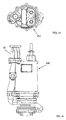
- FIG. 3 is a front view of the sewage grinder pump shown in FIG. 1 ;
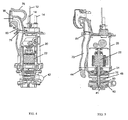
- FIG. 4 is a cross-sectional view of the sewage grinder pump shown in FIG. 2 taken along line 4-4;
- FIG. 5 is a cross-sectional view of the sewage grinder pump shown in FIG. 2 taken along line 5-5;
- FIG. 6 is a rear view of the sewage grinder pump shown in FIG. 1 ;
- FIG. 7 is an enlarged cross-sectional view of the lower portion of the sewage grinder pump shown in FIG. 5 ;
- FIG. 8 is a bottom view of the sewage grinder pump shown in FIG. 1 ;
- FIG. 9 is a bottom view of the first stage impeller shown in FIGS. 4 and 5 ;
- FIG. 10 is a bottom view of the second stage impeller shown in FIGS. 4 and 5 ;
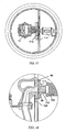
- FIG. 11 is a cross-sectional view of the anti-siphon valve shown in FIG. 3 , taken on line 11-11;
- FIG. 12 is a cross-sectional view of the anti-siphon valve shown in FIG. 3 , taken on line 12-12;
- FIG. 13 is a cross-sectional view of a check valve integral with a discharge conduit
- FIG. 14 is a front view of a single stage sewage grinder pump
- FIG. 15 is a top view of an additional embodiment of the two-stage sewage grinder pump according to the present invention.
- FIG. 16 is a front view of the two-stage sewage grinder pump shown in FIG. 15 .
- FIG. 17 is a horizontal cross-sectional view of a portion of the sewage grinder pump and basin shown in FIG. 1 ;
- FIG. 18 is a vertical cross-sectional view of the details of the connection of the sewage grinder pump to the sewage discharge.
- FIG. 19 is a general plot showing the relationship between pressure head versus flow rate for the sewage grinder pump shown in FIG 1 .
- FIG. 1 shows a basin 100 with a sewage grinder pump 10 according to the present invention installed within the basin.
- the basin 100 has a sewage inlet 102 that receives sewage from a home, business or other source. Sewage flows into basin 100 through the sewage inlet 102 and drops to the bottom of the basin. Sewage grinder pump 10 sits within the basin 100 on pump supports 108, 109, attached to support wall 114, that raise the pump inlet 41 above the bottom of the basin.
- the pump discharge fluid conduit 80 is connected to sewage outlet 110.
- An isolation valve 104 with an extended operator handle 106 is provided to isolate sewage grinder pump 10 from the sewage outlet 110 to allow maintenance or removal of the sewage grinder pump.
- Sewage grinder pump 10 is further supported within basin 100 by a suspension cable 12.
- a pair of electrical conduits 14 provide electrical power and control signals to sewage grinder pump 10.
- the pump control system turns the pump on. Sewage and any entrained solids enter the pump inlet 41 where the solids are reduced in size in grinder 60. The pressure of the sewage and the contained comminuted solids is then raised by the two stages of vortex impellers 30, 32.
- the pump motor 22 is a 2 HP motor and the sewage grinder pump 10 has a shutoff head greater than about 200 feet and a maximum flow greater than about 30 gallons per minute, as shown in FIG. 19 .
- sewage grinder pump 10 is provided with a plurality of pumping stages, see FIGS. 1 through 8 .
- sewage grinder pump 10' is provided as a single stage pump, see FIG. 14 .
- the major components of sewage grinder pump 10 are shown.
- the major components of pump 10 are the pump housing 40, the motor housing 20 and discharge conduit 70 monolithic therewith, and discharge flange 75.
- Discharge flange 75 is provided in multiple configurations, see FIGS. 15 and 16 .
- the pump housing 40 houses the grinder 60 and two stages of vortex impellers 30, 32.
- the pump housing has an inlet section 41, an inter-stage conduit 42 and an outlet 44.
- the grinder 60 is positioned within the inlet section 41 and includes a rotating cutter 66 positioned within a stationary shredding ring 64.
- the rotating cutter 66 includes a plurality of cutters 68 (shown in FIG. 8 ) and has a plurality of slots 61 formed in the outer periphery of the rotating cutter 66.
- the slots 61 extend from the outer face of the rotating cutter 66 to the inner face of the rotating cutter.
- the stationary shredding ring 64 has a plurality of channels 46 formed in the inner periphery of the stationary shredding ring 64.
- Channels 46 also extend from the outer face of the shredding ring 64 to the inner face of the shredding ring. In addition to the comminuting action of the cutters 68, additional shredding takes place between the slots 61 and the channels 46. Also, the slots 61 and channels 46 act to throttle the inlet flow to the first stage impeller 30.
- First stage impeller 30 increases the pressure and discharges into discharge passage 43, where the sewage passes into the inter-stage conduit 42 and enters the second stage volute 56 via second stage inlet 45.
- Second stage impeller 32 increases the pressure to the final discharge pressure and the sewage passes into the second stage outlet 47 and into pump housing outlet 44.
- impellers 30, 32 are both vortex impellers. As shown in FIGS. 9 and 10 , the impellers are similar. Each impeller has a plurality of pumping vanes 31, 33, respectively, on the pumping face of the impeller. If needed, second stage impeller can include pump out vanes (not numbered) on the rear face of the impeller.
- the first stage impeller 30 is 1 ⁇ 4 inch larger in diameter than the second stage impeller 32.
- the first stage volute 55 is also slightly larger than the second stage volute 56.
- the pressure increase is divided about 50-50 between the first stage and the second stage.
- motor shaft 24 is attached to motor 22.
- the upper end of motor shaft 24 is enclosed within seal plate 52 that is attached to motor enclosure 20 by a plurality of bolts (not numbered).
- the shaft 24 is rotatably supported by bearing 48.
- Below bearing 48 is a stationary seal 51 with a rotating mechanical seal 49 biased into contact with the stationary seal 51 by spring 50.
- the second stage impeller 32 is threaded onto shaft sleeve 53 and sleeve 53 is then threaded onto shaft 24.
- First stage impeller 30 is attached to shaft 24 by rotating cutter 66, which is attached to shaft 24 by bolt 58.
- a suction cover 62 is attached to the lower end of pump housing 40. Rotating cutter 66 and stationary shredding ring 64 fit within a central aperture in suction cover 62.
- Impellers 30, 32 and grinder 60 are preferably attached to the same shaft and, more preferably, the impellers 30, 32 are positioned between the motor 22 and the grinder 66.
- the discharge conduit 70 is monolithic with motor housing 20.
- motor housing 20 and discharge conduit 70 are a monolithic casting.
- the discharge conduit 70 is positioned external to the portion of motor housing 20 that encloses motor 22.
- the discharge 70 connects the pump housing outlet 44 to the inlet 81 of the discharge flange 75.
- Discharge conduit 70 has an anti-siphon valve 71 integral therewith.
- Anti-siphon valve 71 is positioned in a side of the discharge conduit 70 and acts to prevent siphoning from basin 100 in the event a break occurs in a downstream section of the sewer pipe.
- Anti-siphon valve 71 includes a removable cover 67 attached over an opening in the side of discharge conduit 70.
- the cover 67 forms a downwardly directed outlet 63.
- the inside of cover 67 forms a valve seat 72 for movable valve 73.
- Movable valve 73 is formed from an elastomeric material sandwiched between stainless steel washers riveted together. An end portion of movable valve 73 is sandwiched between cover 67 and discharge conduit 70.
- the section of movable valve 73 adjacent to the stainless steel washers forms a living hinge 91 that permits movable valve 73 to move off the valve seat 72.
- Movable valve 73 opens in the direction indicated by arrow 65.
- the center of movable valve includes a bleeder 69 that forms a bleed path to allow both air and liquid to pass through the movable valve. This helps to prevent sticking of the anti-siphon valve 71 and can bleed any air within the pump and discharge conduit upon startup.
- Formed in discharge conduit 70 are stops 74 that prevent movable valve 73 from inadvertently being pulled into the flowing liquid within discharge conduit 70.
- Discharge flange 75 Attached to the top of motor housing 20 is discharge flange 75.
- Discharge flange 75 has a lift handle 76 formed therein.
- a fluid conduit 80 having an inlet 81 and an outlet 82.
- the inlet 81 of fluid conduit 80 is connected to the discharge of discharge conduit 70.
- Integral with discharge flange 75 is a check valve 78.
- Check valve 78 includes a removable valve seat 79 positioned within the inlet 81 of the fluid conduit 80.
- a movable valve 77 is attached to the valve seat 79.
- Check valve movable valve 77 is similar to anti-siphon movable valve 73, but does not include bleeder 69.
- check valve 78 is integral with discharge flange 75, installation of sewage grinder pump 10 is simplified by eliminating the need to provide additional piping with a separate check valve.
- Other configurations of pumps can be accommodated by providing discharge flanges 75 in various configurations (see FIGS. 13 and 16 ).
- the sewage grinder pump 10 of the present invention can be retro-fitted as a replacement for other style pumps.
- One such retro-fit pump 200 is shown in FIG. 16 .
- a sewage grinder pump 200 comprising a pump and motor housing similar to that shown in the FIGURES for sewage grinder pump 10 is supplied.
- An appropriate discharge flange 75 is selected from a plurality of discharge flanges having various configurations.
- the discharge flange 75 is attached to pump housing 20.
- the pump 200 is positioned within the basin and the discharge flange 75 is attached to the sewage outlet connection.
- discharge flange 75 includes a connector assembly 84 for connecting the discharge of sewage grinder pump 10 to the sewage outlet 110 via a connecting conduit 116 and isolation valve 104.
- the connector assembly 84 includes a flange 89 that slidably engages a connecting flange 112 attached to support wall 114 (see FIG. 17 ).
- an elastomeric seal 86 having a central aperture is attached to flange 89 by a retainer ring 90.
- the elastomeric seal 86 has a conical shape so that a central portion 88 of the elastomeric seal extends outwardly from flange 89 and engages the surface of connecting conduit mounting assembly 117 to seal the discharge of sewage grinder pump 10 to the connecting conduit 116.
- Sewage grinder pump 10 is installed by lowering the pump 10 into the basin 100 using suspension cable 12 and lift handle 76.
- Flange 89 is slid into the C-shaped basin connecting flange 112 with the elastomeric seal 86 engaging the connecting conduit mounting assembly 117 about the connecting conduit 116 to seal sewage grinder pump 10 to the sewage outlet.
- Flange 89 sits upon upper support 108 and a flange on the lower end of motor housing 20 sits upon lower support 109 to support sewage grinder pump 10 within basin 100.
Landscapes
- Engineering & Computer Science (AREA)
- Mechanical Engineering (AREA)
- General Engineering & Computer Science (AREA)
- Health & Medical Sciences (AREA)
- Life Sciences & Earth Sciences (AREA)
- Hydrology & Water Resources (AREA)
- Public Health (AREA)
- Water Supply & Treatment (AREA)
- Structures Of Non-Positive Displacement Pumps (AREA)
- Crushing And Pulverization Processes (AREA)
Description
- This application claims priority from provisional application serial no.
60/511,288, filed October 14, 2003 - This invention relates generally to sewage grinder pumps and more particularly to two-stage high head low flow sewage grinder pumps.
- Many residential sewer systems use only the force of gravity to provide for discharging its wastewater into progressively larger sewer mains and ultimately to a dedicated treatment plant that is usually located in a low-lying area such that gravity can assist the flow of sewage. However, in a hilly land area, in a below-grade setting, along long horizontal pipe runs or perhaps due to smaller-diameter piping restrictions, gravity often will not suffice. In such situations, a lift-station or a stand-alone sewage ejector pump is required if gravity alone will not allow flow of sewage at a speed of at least 2 feet per second, which is considered to be a minimum required velocity to maintain suspended sewage solids in suspension. One type of ejector pump is a submersible grinder pump. In areas of low pressure, one can employ such a fixture to move the sewage from a given location to a sewage collection system. The pump may be installed below the nearest available sewer line. The pump will either lift the waste to the level of the main drain or move the sewage though the piping.
- Grinder pumps cut and grind solid materials into tiny pieces and are designed to reduce sewage particulate to a slurry. This overcomes sewage passageways restrictions and allows free movement of the fluid. A commonly used submersible grinder pump is a centrifugal pump with a recessed vortex impeller. In these systems, one can expect a power range of 2 to 7.5 horsepower (HP). Residences generally use the 2 HP models, principally due to its compatibility with typical residential electric-circuit configurations that provide comparatively low power. However, one may require a larger HP centrifugal pump, an intermediate lift station, or a progressing cavity style pump when sewer system pressures or flow resistance exceeds the capabilities of a 2 HP centrifugal pump. In residential applications, such systems are often unaffordable.
- The progressing cavity pump's major advantage is its ability to work under relatively high pressures and allow service to areas with high-pressure requirements without the need for additional lift stations or relatively high HP pumps. Unfortunately, wear items that readily fail at high pressures, such as that pump's wobble stator arrangement, are a significant disadvantage.
- Alternatively, centrifugal pumps offer higher flow rates than progressing cavity style pumps, have the ability to handle abrasives and slurries, and can operate at stall head or zero flow for extended periods without causing pump damage. For example, design pressures can be readily exceeded and can remain high until an upset condition, such as excessive simultaneous operations following a power outage, or high infiltration caused by poor installation, is resolved. However, a 2 HP residential centrifugal pump will have a significantly lower pressure limitation than a progressing cavity pump and is not suited for pressure sewer systems that achieve a total system head (distance pump is capable of lifting fluid) greater than 120 feet at the pump.
- Thus, in a pressure sewer system where upset conditions produce high system pressures, both the progressing cavity and typical single-stage centrifugal grinder pumps lack relevant design efficiencies and possess limiting capabilities. However, since the centrifugal pump with recessed vortex impeller is more robust and reliable, a welcome pump design modification will combine this advantage with the high-pressure advantage of the progressing cavity pump to produce a pump that is affordable and still suitable to residential applications.
- The foregoing illustrates limitations known to exist in present sewage grinder pumps. Thus, it is apparent that it would be advantageous to provide an alternative directed to overcoming one or more of the limitations set forth above. Accordingly, a suitable alternative is provided including features more fully disclosed hereinafter.
- In one aspect of the present invention, this is accomplished by providing a sewage grinder pump comprising: a housing; a motor enclosed within the housing, the motor having a shaft extending therefrom; a plurality of impellers attached to the motor shaft; and a grinder attached to the motor shaft, the grinder and the plurality of impellers having a common axis of rotation.
- In another aspect of the present invention, this is accomplished by providing a sewage grinder pump comprising: a housing; a motor enclosed within the housing, the motor having a shaft extending therefrom; a pump attached to the motor shaft; and a grinder at-centrifugal pump with recessed vortex impeller is more robust and reliable, a welcome pump design modification will combine this advantage with the high-pressure advantage of the progressing cavity pump to produce a pump that is affordable and still suitable to residential applications.
-
WO 00/01490 - The foregoing illustrates limitations known to exist in present sewage grinder pumps. Thus, it is apparent that it would be advantageous to provide an alternative directed to overcoming one or more of the limitations set forth above. Accordingly, a suitable alternative is provided including features more fully disclosed hereinafter.
- In one aspect of the present invention, this is accomplished by providing a sewage grinder pump comprising: a housing; a motor enclosed within the housing, the motor having a shaft extending therefrom; a plurality of impellers attached to the motor shaft; and a grinder attached to the motor shaft, the grinder and the plurality of impellers having a common axis of rotation.
- In another aspect of the present invention, this is accomplished by providing a sewage grinder pump comprising: a housing; a motor enclosed within the housing, the motor having a shaft extending therefrom; a pump attached to the motor shaft; and a grinder attached to the motor shaft, the housing having a discharge conduit monolithic therewith, the discharge conduit being in fluid communication with the pump.
- In another aspect of the present invention, this is accomplished by providing a method for grinding and pumping sewage comprising: providing a motor having a shaft extending therefrom with a first stage impeller, a second stage impeller and a grinder attached thereto; operating the motor to rotate the attached impellers and grinder; sewage grinder pump with the attached discharge flange within the basin; attaching the discharge flange to a sewage outlet connection.
- In another aspect of the present invention, this is accomplished by providing a sewage grinder pump comprising: a housing; a motor enclosed within the housing, the motor having a shaft extending therefrom; a pump operably attached to the motor shaft; a grinder operably attached to the motor shaft; and a discharge flange attached to the housing, the discharge flange being in fluid communication with the pump, the discharge flange having a connector assembly, the connector assembly adapted to connect the discharge flange to a sewage outlet, the connector assembly including an elastomeric seal for sealingly engaging the sewage outlet.
- The foregoing and other aspects will become apparent from the following detailed description of the invention when considered in conjunction with the accompanying drawing figures.
-
FIG. 1 is a cross-sectional view of a two-stage sewage grinder pump according to the present invention installed in a basin; -
FIG. 2 is a top view of the sewage grinder pump shown inFIG. 1 ; -
FIG. 3 is a front view of the sewage grinder pump shown inFIG. 1 ; -
FIG. 4 is a cross-sectional view of the sewage grinder pump shown inFIG. 2 taken along line 4-4; -
FIG. 5 is a cross-sectional view of the sewage grinder pump shown inFIG. 2 taken along line 5-5; -
FIG. 6 is a rear view of the sewage grinder pump shown inFIG. 1 ; -
FIG. 7 is an enlarged cross-sectional view of the lower portion of the sewage grinder pump shown inFIG. 5 ; -
FIG. 8 is a bottom view of the sewage grinder pump shown inFIG. 1 ; -
FIG. 9 is a bottom view of the first stage impeller shown inFIGS. 4 and 5 ; -
FIG. 10 is a bottom view of the second stage impeller shown inFIGS. 4 and 5 ; -
FIG. 11 is a cross-sectional view of the anti-siphon valve shown inFIG. 3 , taken on line 11-11; -
FIG. 12 is a cross-sectional view of the anti-siphon valve shown inFIG. 3 , taken on line 12-12; -
FIG. 13 is a cross-sectional view of a check valve integral with a discharge conduit; -
FIG. 14 is a front view of a single stage sewage grinder pump; -
FIG. 15 is a top view of an additional embodiment of the two-stage sewage grinder pump according to the present invention; -
FIG. 16 is a front view of the two-stage sewage grinder pump shown inFIG. 15 . -
FIG. 17 is a horizontal cross-sectional view of a portion of the sewage grinder pump and basin shown inFIG. 1 ; -
FIG. 18 is a vertical cross-sectional view of the details of the connection of the sewage grinder pump to the sewage discharge; and -
FIG. 19 is a general plot showing the relationship between pressure head versus flow rate for the sewage grinder pump shown inFIG 1 . -
FIG. 1 shows abasin 100 with asewage grinder pump 10 according to the present invention installed within the basin. Thebasin 100 has asewage inlet 102 that receives sewage from a home, business or other source. Sewage flows intobasin 100 through thesewage inlet 102 and drops to the bottom of the basin.Sewage grinder pump 10 sits within thebasin 100 on pump supports 108, 109, attached to supportwall 114, that raise thepump inlet 41 above the bottom of the basin. The pump dischargefluid conduit 80 is connected tosewage outlet 110. Anisolation valve 104 with an extended operator handle 106 is provided to isolate sewage grinder pump 10 from thesewage outlet 110 to allow maintenance or removal of the sewage grinder pump. -
Sewage grinder pump 10 is further supported withinbasin 100 by asuspension cable 12. A pair ofelectrical conduits 14 provide electrical power and control signals tosewage grinder pump 10. - In operation, as the sewage level in
basin 100 rises to a predetermined level, the pump control system turns the pump on. Sewage and any entrained solids enter thepump inlet 41 where the solids are reduced in size ingrinder 60. The pressure of the sewage and the contained comminuted solids is then raised by the two stages ofvortex impellers pump motor 22 is a 2 HP motor and thesewage grinder pump 10 has a shutoff head greater than about 200 feet and a maximum flow greater than about 30 gallons per minute, as shown inFIG. 19 . - In one embodiment,
sewage grinder pump 10 is provided with a plurality of pumping stages, seeFIGS. 1 through 8 . In an alternate embodiment, sewage grinder pump 10' is provided as a single stage pump, seeFIG. 14 . - Referring to
FIGS. 2 through 8 , the major components ofsewage grinder pump 10 are shown. The major components ofpump 10 are thepump housing 40, themotor housing 20 anddischarge conduit 70 monolithic therewith, and dischargeflange 75.Discharge flange 75 is provided in multiple configurations, seeFIGS. 15 and 16 . Thepump housing 40 houses thegrinder 60 and two stages ofvortex impellers - Starting with the
pump housing 40, shown in an enlarged cross-section inFIG. 7 , the pump housing has aninlet section 41, aninter-stage conduit 42 and anoutlet 44. Thegrinder 60 is positioned within theinlet section 41 and includes arotating cutter 66 positioned within astationary shredding ring 64. Therotating cutter 66 includes a plurality of cutters 68 (shown inFIG. 8 ) and has a plurality ofslots 61 formed in the outer periphery of therotating cutter 66. Theslots 61 extend from the outer face of therotating cutter 66 to the inner face of the rotating cutter. Thestationary shredding ring 64 has a plurality ofchannels 46 formed in the inner periphery of thestationary shredding ring 64.Channels 46 also extend from the outer face of the shreddingring 64 to the inner face of the shredding ring. In addition to the comminuting action of thecutters 68, additional shredding takes place between theslots 61 and thechannels 46. Also, theslots 61 andchannels 46 act to throttle the inlet flow to thefirst stage impeller 30. - From the
grinder 60, the sewage flows into thefirst stage volute 55.First stage impeller 30 increases the pressure and discharges intodischarge passage 43, where the sewage passes into theinter-stage conduit 42 and enters thesecond stage volute 56 viasecond stage inlet 45.Second stage impeller 32 increases the pressure to the final discharge pressure and the sewage passes into thesecond stage outlet 47 and intopump housing outlet 44. - Preferably,
impellers FIGS. 9 and 10 , the impellers are similar. Each impeller has a plurality of pumpingvanes first stage impeller 30 is ¼ inch larger in diameter than thesecond stage impeller 32. Thefirst stage volute 55 is also slightly larger than thesecond stage volute 56. Typically, the pressure increase is divided about 50-50 between the first stage and the second stage. - Referring again to
FIG. 7 ,motor shaft 24 is attached tomotor 22. The upper end ofmotor shaft 24 is enclosed withinseal plate 52 that is attached tomotor enclosure 20 by a plurality of bolts (not numbered). Withinseal plate 52, theshaft 24 is rotatably supported by bearing 48. Below bearing 48 is astationary seal 51 with a rotatingmechanical seal 49 biased into contact with thestationary seal 51 byspring 50. Thesecond stage impeller 32 is threaded ontoshaft sleeve 53 andsleeve 53 is then threaded ontoshaft 24.First stage impeller 30 is attached toshaft 24 by rotatingcutter 66, which is attached toshaft 24 bybolt 58. Asuction cover 62 is attached to the lower end ofpump housing 40. Rotatingcutter 66 andstationary shredding ring 64 fit within a central aperture insuction cover 62. -
Impellers grinder 60 are preferably attached to the same shaft and, more preferably, theimpellers motor 22 and thegrinder 66. - The
discharge conduit 70 is monolithic withmotor housing 20. Preferably,motor housing 20 anddischarge conduit 70 are a monolithic casting. Thedischarge conduit 70 is positioned external to the portion ofmotor housing 20 that enclosesmotor 22. Thedischarge 70 connects thepump housing outlet 44 to theinlet 81 of thedischarge flange 75. Dischargeconduit 70 has ananti-siphon valve 71 integral therewith. - Details of
anti-siphon 71 are shown inFIGS. 11 and 12 .Anti-siphon valve 71 is positioned in a side of thedischarge conduit 70 and acts to prevent siphoning frombasin 100 in the event a break occurs in a downstream section of the sewer pipe.Anti-siphon valve 71 includes aremovable cover 67 attached over an opening in the side ofdischarge conduit 70. Thecover 67 forms a downwardly directedoutlet 63. The inside ofcover 67 forms avalve seat 72 formovable valve 73.Movable valve 73 is formed from an elastomeric material sandwiched between stainless steel washers riveted together. An end portion ofmovable valve 73 is sandwiched betweencover 67 anddischarge conduit 70. The section ofmovable valve 73 adjacent to the stainless steel washers forms a livinghinge 91 that permitsmovable valve 73 to move off thevalve seat 72.Movable valve 73 opens in the direction indicated byarrow 65. The center of movable valve includes ableeder 69 that forms a bleed path to allow both air and liquid to pass through the movable valve. This helps to prevent sticking of theanti-siphon valve 71 and can bleed any air within the pump and discharge conduit upon startup. Formed indischarge conduit 70 arestops 74 that preventmovable valve 73 from inadvertently being pulled into the flowing liquid withindischarge conduit 70. - Attached to the top of
motor housing 20 isdischarge flange 75.Discharge flange 75 has alift handle 76 formed therein. Withindischarge flange 75 is afluid conduit 80 having aninlet 81 and anoutlet 82. Theinlet 81 offluid conduit 80 is connected to the discharge ofdischarge conduit 70. Integral withdischarge flange 75 is acheck valve 78. Checkvalve 78 includes aremovable valve seat 79 positioned within theinlet 81 of thefluid conduit 80. Amovable valve 77 is attached to thevalve seat 79. Check valvemovable valve 77 is similar to anti-siphonmovable valve 73, but does not includebleeder 69. - Because
check valve 78 is integral withdischarge flange 75, installation ofsewage grinder pump 10 is simplified by eliminating the need to provide additional piping with a separate check valve. Other configurations of pumps can be accommodated by providingdischarge flanges 75 in various configurations (seeFIGS. 13 and16 ). - The
sewage grinder pump 10 of the present invention can be retro-fitted as a replacement for other style pumps. One such retro-fit pump 200 is shown inFIG. 16 . To retro-fit a pump, asewage grinder pump 200 comprising a pump and motor housing similar to that shown in the FIGURES forsewage grinder pump 10 is supplied. Anappropriate discharge flange 75 is selected from a plurality of discharge flanges having various configurations. Thedischarge flange 75 is attached to pumphousing 20. Next thepump 200 is positioned within the basin and thedischarge flange 75 is attached to the sewage outlet connection. - In one embodiment,
discharge flange 75 includes aconnector assembly 84 for connecting the discharge ofsewage grinder pump 10 to thesewage outlet 110 via a connectingconduit 116 andisolation valve 104. Theconnector assembly 84 includes aflange 89 that slidably engages a connectingflange 112 attached to support wall 114 (seeFIG. 17 ). In the face of connector assembly 84 (as shown inFIG. 6 ), anelastomeric seal 86 having a central aperture is attached to flange 89 by aretainer ring 90. Theelastomeric seal 86 has a conical shape so that acentral portion 88 of the elastomeric seal extends outwardly fromflange 89 and engages the surface of connectingconduit mounting assembly 117 to seal the discharge ofsewage grinder pump 10 to the connectingconduit 116. -
Sewage grinder pump 10 is installed by lowering thepump 10 into thebasin 100 usingsuspension cable 12 and lift handle 76.Flange 89 is slid into the C-shapedbasin connecting flange 112 with theelastomeric seal 86 engaging the connectingconduit mounting assembly 117 about the connectingconduit 116 to sealsewage grinder pump 10 to the sewage outlet.Flange 89 sits uponupper support 108 and a flange on the lower end ofmotor housing 20 sits uponlower support 109 to supportsewage grinder pump 10 withinbasin 100.
Claims (11)
- A sewage grinder pump (10) comprising:a motor housing (20);a pump housing (40);a motor (22) enclosed within the motor housing (20), the motor having a shaft (24) extending therefrom into the pump housing (40);a grinder (60) positioned in the pump housing (40) inlet and attached to the motor shaft (24), the grinder (60) and the centrifugal impellers(30, 32) having a common axis of rotation inside the pump housing (40), andcharacterised by: the pump housing (40) having an inlet (41) communicated to a first stage volute (55), a discharge (43) of the first stage volute (55) communicated through an inter-stage conduit (42) to an inlet of a second stage volute (56) and a discharge of the second stage volute communicated to an outlet (44);
first and second stage centrifugal impellers (30,32) positioned in the respective first and second stage volutes (55,56), each of the centrifugal impellers (30,32) attached to the motor shaft (24) between the motor and the grinder 60, - The sewage grinder pump (10) according to claim 1, wherein the motor shaft (24) extends vertically.
- The sewage grinder pump (10) according to claim 1, wherein at least one of the centrifugal impellers (30,32) is a vortex impeller.
- The sewage grinder pump (10) according to claim 1, wherein the grinder (60) further comprises a means for throttling inlet flow.
- The sewage grinder pump (10) according to claim 1, further comprising a discharge conduit (70) monolithic with the motor housing (20) and communicated to the pump housing outlet (44).
- The sewage grinder pump (10) according to claim 5, wherein the discharge conduit (70) has an anti-siphon valve (71) integral therewith, the anti-siphon valve (71) comprising a valve seat (72) and a movable valve element (73).
- The sewage grinder pump (10) according to claim 6, wherein the anti-siphon valve (71) further comprises a means for bleeding fluid.
- The sewage grinder pump (10) according to claim 6, wherein the anti-siphon valve (71) further comprises a stop, the stop being positioned between the movable valve element (73) and the interior of the discharge conduit (70).
- The sewage grinder pump (10) according to claim 6, wherein the movable valve element (73) lies in a plane that is inclined from vertical.
- The sewage grinder pump (10) according to claim 5, further comprising:a discharge flange (75) attached to the motor housing (20), the discharge flange (75) in fluid communication with the discharge conduit (70); anda check valve (78) integral with the discharge flange (75).
- The sewage grinder pump (10) according to claim 10, wherein the discharge flange (75) has a lift handle monolithic therewith.
Applications Claiming Priority (2)
| Application Number | Priority Date | Filing Date | Title |
|---|---|---|---|
| US51128803P | 2003-10-14 | 2003-10-14 | |
| PCT/IB2004/052100 WO2005035447A2 (en) | 2003-10-14 | 2004-10-14 | Two stage sewage grinder pump |
Publications (3)
| Publication Number | Publication Date |
|---|---|
| EP1689529A2 EP1689529A2 (en) | 2006-08-16 |
| EP1689529A4 EP1689529A4 (en) | 2009-07-22 |
| EP1689529B1 true EP1689529B1 (en) | 2013-01-23 |
Family
ID=34435147
Family Applications (1)
| Application Number | Title | Priority Date | Filing Date |
|---|---|---|---|
| EP04770260A Expired - Lifetime EP1689529B1 (en) | 2003-10-14 | 2004-10-14 | Two stage sewage grinder pump |
Country Status (7)
| Country | Link |
|---|---|
| US (1) | US7357341B2 (en) |
| EP (1) | EP1689529B1 (en) |
| AU (1) | AU2004279619B2 (en) |
| CA (1) | CA2540556C (en) |
| DK (1) | DK1689529T3 (en) |
| MX (1) | MXPA06004143A (en) |
| WO (1) | WO2005035447A2 (en) |
Families Citing this family (20)
| Publication number | Priority date | Publication date | Assignee | Title |
|---|---|---|---|---|
| US8594851B1 (en) * | 2006-12-20 | 2013-11-26 | Data Flow Systems, Inc. | Wastewater collection flow management system and techniques |
| US8983667B2 (en) | 2006-12-20 | 2015-03-17 | Data Flow Systems, Inc. | Fluid flow management through a wastewater level manipulation system and associated methods |
| US8128360B2 (en) * | 2007-11-12 | 2012-03-06 | Crane Pumps & Systems, Inc. | Vortex pump with splitter blade impeller |
| US8500393B2 (en) * | 2008-09-30 | 2013-08-06 | The Gorman-Rupp Company | Chopper pump |
| US8152449B2 (en) | 2008-12-10 | 2012-04-10 | Honeywell International Inc. | Vacuum generator seal |
| US8376254B2 (en) | 2009-06-30 | 2013-02-19 | Anue Water Technologies, Inc. | Water treatment systems and methods |
| CA2774938A1 (en) | 2009-09-22 | 2011-03-31 | Anue Water Technologies, Inc. | Waste water treatment systems and methods |
| US20150285252A1 (en) * | 2012-11-02 | 2015-10-08 | Crane Pumps & Systems, Inc. | Grinder pump with regenerative impeller |
| FR3006720A1 (en) | 2013-06-10 | 2014-12-12 | Ksb Sas | AUBES KNIFE AND DILACERATOR PUMP COMPRISING SAME |
| US11136983B2 (en) | 2016-11-10 | 2021-10-05 | Wayne/Scott Fetzer Company | Dual inlet volute, impeller and pump housing for same, and related methods |
| USD868117S1 (en) | 2017-04-05 | 2019-11-26 | Wayne/Scott Fetzer Company | Pump component |
| USD986287S1 (en) | 2017-04-05 | 2023-05-16 | Wayne/Scott Fetzer Company | Pump component |
| EP3404265A1 (en) | 2017-05-15 | 2018-11-21 | Sulzer Management AG | Multistage centrifugal grinder pump |
| CN107410044A (en) * | 2017-07-28 | 2017-12-01 | 南京拜思特环保设备有限公司 | One kind cultivation animal husbandry dredge pump installation integrating device |
| ES2970331T3 (en) | 2017-12-04 | 2024-05-28 | Sulzer Management Ag | Grinding assembly for a grinding pump and a centrifugal grinding pump |
| ES2969909T3 (en) * | 2018-02-23 | 2024-05-23 | Sulzer Management Ag | Multistage Centrifugal Crusher Pump |
| CN120299604A (en) * | 2018-05-14 | 2025-07-11 | 费森尤斯维尔公司 | Compiler system, method for providing a drug library to a patient device, and computer system for providing a drug library to an infusion pump |
| US11471893B2 (en) * | 2020-07-02 | 2022-10-18 | Crane Pumps & Systems, Inc. | Grinder accessory for pump |
| CN112253474A (en) * | 2020-09-23 | 2021-01-22 | 辽宁三三工业有限公司 | Pipeline countercurrent automatic blocking device for centrifugal pump system |
| CN117413125A (en) | 2021-06-16 | 2024-01-16 | 创科无线普通合伙 | Portable pump with telescopic tube |
Family Cites Families (5)
| Publication number | Priority date | Publication date | Assignee | Title |
|---|---|---|---|---|
| US3650481A (en) * | 1971-04-01 | 1972-03-21 | Hydr O Matic Pump Co | Grinder pump |
| US4135852A (en) * | 1977-03-28 | 1979-01-23 | Mcnally Mountain States Steel Company | Centrifugal slurry pump and method |
| US6010086A (en) | 1998-07-02 | 2000-01-04 | Enviroment One Corporation | Grinder pump |
| US6190121B1 (en) * | 1999-02-12 | 2001-02-20 | Hayward Gordon Limited | Centrifugal pump with solids cutting action |
| US6916152B2 (en) | 2003-06-13 | 2005-07-12 | Robert M. Keener | Centrifugal sewage pumps with two impellers |
-
2004
- 2004-10-14 DK DK04770260.0T patent/DK1689529T3/en active
- 2004-10-14 US US10/595,301 patent/US7357341B2/en not_active Expired - Lifetime
- 2004-10-14 CA CA2540556A patent/CA2540556C/en not_active Expired - Lifetime
- 2004-10-14 EP EP04770260A patent/EP1689529B1/en not_active Expired - Lifetime
- 2004-10-14 MX MXPA06004143A patent/MXPA06004143A/en active IP Right Grant
- 2004-10-14 WO PCT/IB2004/052100 patent/WO2005035447A2/en not_active Ceased
- 2004-10-14 AU AU2004279619A patent/AU2004279619B2/en not_active Expired
Also Published As
| Publication number | Publication date |
|---|---|
| WO2005035447A2 (en) | 2005-04-21 |
| MXPA06004143A (en) | 2006-08-25 |
| DK1689529T3 (en) | 2013-05-06 |
| AU2004279619A2 (en) | 2005-04-21 |
| CA2540556A1 (en) | 2005-04-21 |
| US7357341B2 (en) | 2008-04-15 |
| AU2004279619B2 (en) | 2009-06-18 |
| US20070069050A1 (en) | 2007-03-29 |
| EP1689529A4 (en) | 2009-07-22 |
| WO2005035447A3 (en) | 2005-07-28 |
| AU2004279619A1 (en) | 2005-04-21 |
| EP1689529A2 (en) | 2006-08-16 |
| CA2540556C (en) | 2010-05-18 |
Similar Documents
| Publication | Publication Date | Title |
|---|---|---|
| US7357341B2 (en) | Two stage sewage grinder pump | |
| AU2005220951B2 (en) | Stacked self-priming pump and centrifugal pump | |
| US6241485B1 (en) | Wastewater flow control system | |
| CA1064770A (en) | Flushing liquid system for the wearing ring in centrifugal pumps and the wearing ring assembly and wearing ring for use therein | |
| AU2012267258A1 (en) | Multistage comminuting pump | |
| US8414257B2 (en) | Self-priming centrifugal pump | |
| CN114087201B (en) | Slurry pump capable of adjusting gap between impeller, sheath and guard plate | |
| CA1081044A (en) | Centrifugal slurry pump and method | |
| JP2014156789A (en) | Submersible pump | |
| KR101647422B1 (en) | a strainers for water pumps with Stand Function | |
| CN114593073B (en) | Constant-pressure deep well pump system and control method thereof | |
| CN111706515A (en) | Immersible pump for hydraulic engineering with cutting grinds foreign matter | |
| US4411599A (en) | Drain fitting with built-in pump | |
| CN218376856U (en) | Circulating water pump convenient to adjust | |
| AU2013337715B2 (en) | Grinder pump with regenerative impeller | |
| EP4390134A1 (en) | Submergible multistage pump | |
| JP2009079502A (en) | Submersible pump | |
| JP3218677B2 (en) | Waste crusher | |
| CN116696793A (en) | Pressure relief type submersible pump | |
| JPH06221293A (en) | All round flow type pump | |
| EP3404265A1 (en) | Multistage centrifugal grinder pump | |
| Kessler | Types and Uses of Centrifugal Pumps in Water Utility Engineering | |
| JPH02207191A (en) | Flow automatic adjusting device for crushing pump | |
| Patented | D Revolutionary | |
| NZ614617B2 (en) | Multistage comminuting pump |
Legal Events
| Date | Code | Title | Description |
|---|---|---|---|
| PUAI | Public reference made under article 153(3) epc to a published international application that has entered the european phase |
Free format text: ORIGINAL CODE: 0009012 |
|
| 17P | Request for examination filed |
Effective date: 20060425 |
|
| AK | Designated contracting states |
Kind code of ref document: A2 Designated state(s): AT BE BG CH CY CZ DE DK EE ES FI FR GB GR HU IE IT LI LU MC NL PL PT RO SE SI SK TR |
|
| DAX | Request for extension of the european patent (deleted) | ||
| A4 | Supplementary search report drawn up and despatched |
Effective date: 20090622 |
|
| RIC1 | Information provided on ipc code assigned before grant |
Ipc: F04D 7/04 20060101ALI20090616BHEP Ipc: B02C 1/00 20060101AFI20060523BHEP |
|
| 17Q | First examination report despatched |
Effective date: 20100407 |
|
| GRAP | Despatch of communication of intention to grant a patent |
Free format text: ORIGINAL CODE: EPIDOSNIGR1 |
|
| GRAS | Grant fee paid |
Free format text: ORIGINAL CODE: EPIDOSNIGR3 |
|
| GRAA | (expected) grant |
Free format text: ORIGINAL CODE: 0009210 |
|
| AK | Designated contracting states |
Kind code of ref document: B1 Designated state(s): AT BE BG CH CY CZ DE DK EE ES FI FR GB GR HU IE IT LI LU MC NL PL PT RO SE SI SK TR |
|
| REG | Reference to a national code |
Ref country code: GB Ref legal event code: FG4D |
|
| REG | Reference to a national code |
Ref country code: CH Ref legal event code: EP |
|
| REG | Reference to a national code |
Ref country code: CH Ref legal event code: EP Ref country code: AT Ref legal event code: REF Ref document number: 594654 Country of ref document: AT Kind code of ref document: T Effective date: 20130215 |
|
| REG | Reference to a national code |
Ref country code: IE Ref legal event code: FG4D |
|
| REG | Reference to a national code |
Ref country code: DE Ref legal event code: R096 Ref document number: 602004040865 Country of ref document: DE Effective date: 20130321 |
|
| REG | Reference to a national code |
Ref country code: DK Ref legal event code: T3 |
|
| REG | Reference to a national code |
Ref country code: AT Ref legal event code: MK05 Ref document number: 594654 Country of ref document: AT Kind code of ref document: T Effective date: 20130123 |
|
| REG | Reference to a national code |
Ref country code: NL Ref legal event code: VDEP Effective date: 20130123 |
|
| PG25 | Lapsed in a contracting state [announced via postgrant information from national office to epo] |
Ref country code: CY Free format text: LAPSE BECAUSE OF FAILURE TO SUBMIT A TRANSLATION OF THE DESCRIPTION OR TO PAY THE FEE WITHIN THE PRESCRIBED TIME-LIMIT Effective date: 20130123 Ref country code: AT Free format text: LAPSE BECAUSE OF FAILURE TO SUBMIT A TRANSLATION OF THE DESCRIPTION OR TO PAY THE FEE WITHIN THE PRESCRIBED TIME-LIMIT Effective date: 20130123 Ref country code: BG Free format text: LAPSE BECAUSE OF FAILURE TO SUBMIT A TRANSLATION OF THE DESCRIPTION OR TO PAY THE FEE WITHIN THE PRESCRIBED TIME-LIMIT Effective date: 20130423 Ref country code: SE Free format text: LAPSE BECAUSE OF FAILURE TO SUBMIT A TRANSLATION OF THE DESCRIPTION OR TO PAY THE FEE WITHIN THE PRESCRIBED TIME-LIMIT Effective date: 20130123 Ref country code: ES Free format text: LAPSE BECAUSE OF FAILURE TO SUBMIT A TRANSLATION OF THE DESCRIPTION OR TO PAY THE FEE WITHIN THE PRESCRIBED TIME-LIMIT Effective date: 20130504 Ref country code: BE Free format text: LAPSE BECAUSE OF FAILURE TO SUBMIT A TRANSLATION OF THE DESCRIPTION OR TO PAY THE FEE WITHIN THE PRESCRIBED TIME-LIMIT Effective date: 20130123 |
|
| PG25 | Lapsed in a contracting state [announced via postgrant information from national office to epo] |
Ref country code: PT Free format text: LAPSE BECAUSE OF FAILURE TO SUBMIT A TRANSLATION OF THE DESCRIPTION OR TO PAY THE FEE WITHIN THE PRESCRIBED TIME-LIMIT Effective date: 20130523 Ref country code: PL Free format text: LAPSE BECAUSE OF FAILURE TO SUBMIT A TRANSLATION OF THE DESCRIPTION OR TO PAY THE FEE WITHIN THE PRESCRIBED TIME-LIMIT Effective date: 20130123 Ref country code: NL Free format text: LAPSE BECAUSE OF FAILURE TO SUBMIT A TRANSLATION OF THE DESCRIPTION OR TO PAY THE FEE WITHIN THE PRESCRIBED TIME-LIMIT Effective date: 20130123 Ref country code: FI Free format text: LAPSE BECAUSE OF FAILURE TO SUBMIT A TRANSLATION OF THE DESCRIPTION OR TO PAY THE FEE WITHIN THE PRESCRIBED TIME-LIMIT Effective date: 20130123 Ref country code: GR Free format text: LAPSE BECAUSE OF FAILURE TO SUBMIT A TRANSLATION OF THE DESCRIPTION OR TO PAY THE FEE WITHIN THE PRESCRIBED TIME-LIMIT Effective date: 20130424 Ref country code: SI Free format text: LAPSE BECAUSE OF FAILURE TO SUBMIT A TRANSLATION OF THE DESCRIPTION OR TO PAY THE FEE WITHIN THE PRESCRIBED TIME-LIMIT Effective date: 20130123 |
|
| PG25 | Lapsed in a contracting state [announced via postgrant information from national office to epo] |
Ref country code: EE Free format text: LAPSE BECAUSE OF FAILURE TO SUBMIT A TRANSLATION OF THE DESCRIPTION OR TO PAY THE FEE WITHIN THE PRESCRIBED TIME-LIMIT Effective date: 20130123 Ref country code: SK Free format text: LAPSE BECAUSE OF FAILURE TO SUBMIT A TRANSLATION OF THE DESCRIPTION OR TO PAY THE FEE WITHIN THE PRESCRIBED TIME-LIMIT Effective date: 20130123 Ref country code: RO Free format text: LAPSE BECAUSE OF FAILURE TO SUBMIT A TRANSLATION OF THE DESCRIPTION OR TO PAY THE FEE WITHIN THE PRESCRIBED TIME-LIMIT Effective date: 20130123 Ref country code: CZ Free format text: LAPSE BECAUSE OF FAILURE TO SUBMIT A TRANSLATION OF THE DESCRIPTION OR TO PAY THE FEE WITHIN THE PRESCRIBED TIME-LIMIT Effective date: 20130123 |
|
| PLBE | No opposition filed within time limit |
Free format text: ORIGINAL CODE: 0009261 |
|
| STAA | Information on the status of an ep patent application or granted ep patent |
Free format text: STATUS: NO OPPOSITION FILED WITHIN TIME LIMIT |
|
| PG25 | Lapsed in a contracting state [announced via postgrant information from national office to epo] |
Ref country code: IT Free format text: LAPSE BECAUSE OF FAILURE TO SUBMIT A TRANSLATION OF THE DESCRIPTION OR TO PAY THE FEE WITHIN THE PRESCRIBED TIME-LIMIT Effective date: 20130123 |
|
| 26N | No opposition filed |
Effective date: 20131024 |
|
| REG | Reference to a national code |
Ref country code: DE Ref legal event code: R097 Ref document number: 602004040865 Country of ref document: DE Effective date: 20131024 |
|
| PG25 | Lapsed in a contracting state [announced via postgrant information from national office to epo] |
Ref country code: MC Free format text: LAPSE BECAUSE OF FAILURE TO SUBMIT A TRANSLATION OF THE DESCRIPTION OR TO PAY THE FEE WITHIN THE PRESCRIBED TIME-LIMIT Effective date: 20130123 |
|
| REG | Reference to a national code |
Ref country code: CH Ref legal event code: PL |
|
| REG | Reference to a national code |
Ref country code: DE Ref legal event code: R119 Ref document number: 602004040865 Country of ref document: DE Effective date: 20140501 |
|
| REG | Reference to a national code |
Ref country code: IE Ref legal event code: MM4A |
|
| PG25 | Lapsed in a contracting state [announced via postgrant information from national office to epo] |
Ref country code: LI Free format text: LAPSE BECAUSE OF NON-PAYMENT OF DUE FEES Effective date: 20131031 Ref country code: CH Free format text: LAPSE BECAUSE OF NON-PAYMENT OF DUE FEES Effective date: 20131031 |
|
| REG | Reference to a national code |
Ref country code: FR Ref legal event code: ST Effective date: 20140630 |
|
| PG25 | Lapsed in a contracting state [announced via postgrant information from national office to epo] |
Ref country code: FR Free format text: LAPSE BECAUSE OF NON-PAYMENT OF DUE FEES Effective date: 20131031 Ref country code: DE Free format text: LAPSE BECAUSE OF NON-PAYMENT OF DUE FEES Effective date: 20140501 |
|
| PG25 | Lapsed in a contracting state [announced via postgrant information from national office to epo] |
Ref country code: IE Free format text: LAPSE BECAUSE OF NON-PAYMENT OF DUE FEES Effective date: 20131014 |
|
| PG25 | Lapsed in a contracting state [announced via postgrant information from national office to epo] |
Ref country code: TR Free format text: LAPSE BECAUSE OF FAILURE TO SUBMIT A TRANSLATION OF THE DESCRIPTION OR TO PAY THE FEE WITHIN THE PRESCRIBED TIME-LIMIT Effective date: 20130123 |
|
| PG25 | Lapsed in a contracting state [announced via postgrant information from national office to epo] |
Ref country code: LU Free format text: LAPSE BECAUSE OF NON-PAYMENT OF DUE FEES Effective date: 20131014 Ref country code: HU Free format text: LAPSE BECAUSE OF FAILURE TO SUBMIT A TRANSLATION OF THE DESCRIPTION OR TO PAY THE FEE WITHIN THE PRESCRIBED TIME-LIMIT; INVALID AB INITIO Effective date: 20041014 |
|
| REG | Reference to a national code |
Ref country code: GB Ref legal event code: 732E Free format text: REGISTERED BETWEEN 20220203 AND 20220209 |
|
| P01 | Opt-out of the competence of the unified patent court (upc) registered |
Effective date: 20230516 |
|
| PGFP | Annual fee paid to national office [announced via postgrant information from national office to epo] |
Ref country code: GB Payment date: 20231025 Year of fee payment: 20 |
|
| PGFP | Annual fee paid to national office [announced via postgrant information from national office to epo] |
Ref country code: DK Payment date: 20231025 Year of fee payment: 20 |
|
| REG | Reference to a national code |
Ref country code: DK Ref legal event code: EUP Expiry date: 20241014 |
|
| REG | Reference to a national code |
Ref country code: GB Ref legal event code: PE20 Expiry date: 20241013 |
|
| PG25 | Lapsed in a contracting state [announced via postgrant information from national office to epo] |
Ref country code: GB Free format text: LAPSE BECAUSE OF EXPIRATION OF PROTECTION Effective date: 20241013 |
|
| PG25 | Lapsed in a contracting state [announced via postgrant information from national office to epo] |
Ref country code: GB Free format text: LAPSE BECAUSE OF EXPIRATION OF PROTECTION Effective date: 20241013 |