EP1689286B1 - Stand-up vertical field mri apparatus - Google Patents
Stand-up vertical field mri apparatus Download PDFInfo
- Publication number
- EP1689286B1 EP1689286B1 EP04812587A EP04812587A EP1689286B1 EP 1689286 B1 EP1689286 B1 EP 1689286B1 EP 04812587 A EP04812587 A EP 04812587A EP 04812587 A EP04812587 A EP 04812587A EP 1689286 B1 EP1689286 B1 EP 1689286B1
- Authority
- EP
- European Patent Office
- Prior art keywords
- magnet
- patient
- patient support
- bore
- floor
- Prior art date
- Legal status (The legal status is an assumption and is not a legal conclusion. Google has not performed a legal analysis and makes no representation as to the accuracy of the status listed.)
- Expired - Lifetime
Links
- 230000005291 magnetic effect Effects 0.000 claims description 25
- 238000002595 magnetic resonance imaging Methods 0.000 claims description 20
- 230000003068 static effect Effects 0.000 claims description 13
- 210000002683 foot Anatomy 0.000 description 25
- 238000003384 imaging method Methods 0.000 description 18
- 210000003484 anatomy Anatomy 0.000 description 7
- 238000013519 translation Methods 0.000 description 6
- 230000000712 assembly Effects 0.000 description 4
- 238000000429 assembly Methods 0.000 description 4
- 238000000034 method Methods 0.000 description 4
- 210000001519 tissue Anatomy 0.000 description 4
- 238000012937 correction Methods 0.000 description 3
- 210000002414 leg Anatomy 0.000 description 3
- 210000003141 lower extremity Anatomy 0.000 description 3
- 230000008569 process Effects 0.000 description 3
- 208000024891 symptom Diseases 0.000 description 3
- 210000003423 ankle Anatomy 0.000 description 2
- 238000001816 cooling Methods 0.000 description 2
- 210000003127 knee Anatomy 0.000 description 2
- 230000007246 mechanism Effects 0.000 description 2
- 208000019901 Anxiety disease Diseases 0.000 description 1
- 206010009244 Claustrophobia Diseases 0.000 description 1
- 238000012307 MRI technique Methods 0.000 description 1
- 230000036506 anxiety Effects 0.000 description 1
- 238000013459 approach Methods 0.000 description 1
- 238000007796 conventional method Methods 0.000 description 1
- 239000002826 coolant Substances 0.000 description 1
- 230000006378 damage Effects 0.000 description 1
- 238000013461 design Methods 0.000 description 1
- 238000003745 diagnosis Methods 0.000 description 1
- 230000005284 excitation Effects 0.000 description 1
- 230000005281 excited state Effects 0.000 description 1
- 230000005294 ferromagnetic effect Effects 0.000 description 1
- 230000005484 gravity Effects 0.000 description 1
- 210000001624 hip Anatomy 0.000 description 1
- 238000012986 modification Methods 0.000 description 1
- 230000004048 modification Effects 0.000 description 1
- NJPPVKZQTLUDBO-UHFFFAOYSA-N novaluron Chemical compound C1=C(Cl)C(OC(F)(F)C(OC(F)(F)F)F)=CC=C1NC(=O)NC(=O)C1=C(F)C=CC=C1F NJPPVKZQTLUDBO-UHFFFAOYSA-N 0.000 description 1
- 235000012771 pancakes Nutrition 0.000 description 1
- 208000019899 phobic disease Diseases 0.000 description 1
- 210000004872 soft tissue Anatomy 0.000 description 1
- 239000013598 vector Substances 0.000 description 1
Images


Classifications
-
- G—PHYSICS
- G01—MEASURING; TESTING
- G01R—MEASURING ELECTRIC VARIABLES; MEASURING MAGNETIC VARIABLES
- G01R33/00—Arrangements or instruments for measuring magnetic variables
- G01R33/20—Arrangements or instruments for measuring magnetic variables involving magnetic resonance
- G01R33/28—Details of apparatus provided for in groups G01R33/44 - G01R33/64
- G01R33/30—Sample handling arrangements, e.g. sample cells, spinning mechanisms
- G01R33/307—Sample handling arrangements, e.g. sample cells, spinning mechanisms specially adapted for moving the sample relative to the MR system, e.g. spinning mechanisms, flow cells or means for positioning the sample inside a spectrometer
-
- A—HUMAN NECESSITIES
- A61—MEDICAL OR VETERINARY SCIENCE; HYGIENE
- A61B—DIAGNOSIS; SURGERY; IDENTIFICATION
- A61B5/00—Measuring for diagnostic purposes; Identification of persons
- A61B5/05—Detecting, measuring or recording for diagnosis by means of electric currents or magnetic fields; Measuring using microwaves or radio waves
- A61B5/055—Detecting, measuring or recording for diagnosis by means of electric currents or magnetic fields; Measuring using microwaves or radio waves involving electronic [EMR] or nuclear [NMR] magnetic resonance, e.g. magnetic resonance imaging
-
- G—PHYSICS
- G01—MEASURING; TESTING
- G01R—MEASURING ELECTRIC VARIABLES; MEASURING MAGNETIC VARIABLES
- G01R33/00—Arrangements or instruments for measuring magnetic variables
- G01R33/20—Arrangements or instruments for measuring magnetic variables involving magnetic resonance
- G01R33/28—Details of apparatus provided for in groups G01R33/44 - G01R33/64
- G01R33/38—Systems for generation, homogenisation or stabilisation of the main or gradient magnetic field
- G01R33/381—Systems for generation, homogenisation or stabilisation of the main or gradient magnetic field using electromagnets
- G01R33/3815—Systems for generation, homogenisation or stabilisation of the main or gradient magnetic field using electromagnets with superconducting coils, e.g. power supply therefor
Definitions
- the present invention relates to magnetic resonance imaging apparatus.
- an object to be imaged as, for example, a body of a human subject, is exposed to a strong, substantially constant static magnetic field.
- the static magnetic field causes the spin vectors of certain atomic nuclei within the body to randomly rotate or "precess” around an axis parallel to the direction of the static magnetic field.
- Radio frequency excitation energy is applied to the body, and this energy causes the nuclei to rotate or "precess” in phase and in an excited state.
- weak radio frequency signals are emitted; such radio frequency signals are referred to herein as magnetic resonance signals.
- the magnetic resonance imaging technique offers numerous advantages over other imaging techniques. MRI does not expose either the patient or medical personnel to X-rays and offers important safety advantages. Also, magnetic resonance imaging can obtain images of soft tissues and other features within the body which are not readily visualized using other imaging techniques. Accordingly, magnetic resonance imaging has been widely adopted in the medical and allied arts.
- the position of a patient during magnetic resonance imaging may affect or limit the imaging information obtained.
- a patient may exhibit a symptom if oriented in an upright or weight bearing position and no symptom if oriented in a recumbent or horizontal position.
- it may be necessary to image a patient in an upright or gravity bearing position to discern a symptom and provide a diagnosis for injuries relating to the neck, spine, hip, knee, foot or ankle areas of the human anatomy.
- a magnetic resonance imaging system can be provided with a patient support, such as a table, which can extend in a generally vertical direction so that the long axis of the patient is substantially vertical.
- a patient support such as a table
- Such a support may include a footrest projecting from the table at its lower end and the patient may stand on the footrest.
- the support includes a seat projecting from the table so that the seat is in a horizontal plane when the table surface is vertical.
- the patient support can move relative to the magnet.
- the patient support may be arranged to move vertically relative to the magnet so as to elevate a portion of the patient into the patient-receiving space of the magnet.
- the patient support may be arranged to tilt through a range of orientations between a generally horizontal orientation and a generally vertical orientation.
- the magnets used in the preferred embodiments of the aforementioned '490 and '753 patents typically are arranged so that the magnetic field is directed along a horizontal axis, transverse to the axis of elongation of the patient support and hence transverse to the long axis of the patient.
- a conventional solenoidal magnet where the patient is received inside the bore of the solenoid, the magnetic field is directed along the long axis of the patient.
- U.S. Patent No. 5,349,956 shows a theoretical proposal for a conventional solenoidal magnet having its axis orientated in a vertical direction, with a patient elevator arranged to raise a standing patient into the bore. In theory, such an arrangement could provide for imaging of a patient in an upright position. In practice, this arrangement is never used.
- One aspect of the present invention incorporates the realization that there are mechanical and safety difficulties inherent in this approach, together with problems presented by a cosmic and claustrophobic environment for the patient.
- European patent application 0 067 933 discloses a magnetic resonance imaging apparatus comprising a magnet having a bore extending along a vertical axis and capable of generating a magnetic field parallel to the vertical axis.
- the patient may sit on a seat during MR examination. Alternatively, the patient may be examined standing upright.
- JP2001 104 276 where equipment is provided for transporting the patient into the bore of the magnet.
- the present invention concern a magnetic resonance imaging apparatus comprising a magnet having a bore extending along a vertical axis and capable of generating a magnetic field parallel to the vertical axis; and a patient support device and means arranged to translate said patient support device in a direction parallel to the vertical axis so that a portion of the patient support device becomes situated in said magnet bore, wherein the length of said magnet along a direction parallel to the vertical axis is 1.22 m (four feet) or less, and said magnet and patient support are rotatable between an upright position wherein said magnetic field is parallel to said vertical axis and a recumbent position transverse to said vertical axis when said portion of the patient support device is situated in said magnet bore.
- the apparatus also include a building structure housing said magnet and a magnet support structure connected to the building structure and connected to the magnet.
- the building structure includes a floor and the magnet support is connected to the floor.
- the magnet has an inner bore diameter of 91.4 cm (three feet) or more, however, an inner bore diameter of 45.7 cm (eighteen inches) or more is also suitable.
- the magnet comprises a solenoidal magnet having turns encircling the bore and adapted to generate a static magnetic field having a field direction coaxial with said bore.
- the patient support be mounted to an elevator to raise and lower said patient support device if said magnet and patient support device are in the upright position.
- the magnet preferably has an inner bore diameter of 91.4 cm (three feet) or less.
- the magnet and patient support are positionable in either the Trendelberg or reverse Trendelburg positions.
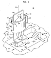
- FIG. 1 is a perspective view of a magnetic resonance imaging apparatus 100 in accordance with an aspect of the present invention.
- the apparatus 100 includes a magnet 104 having a substantially cylindrical central bore 106.
- the magnet 104 is preferably an electromagnet and most preferably a superconducting solenoidal magnet.
- a patient support device or table 110 is positionable within the bore 106 and, as shown, may protrude through each end 108, 109 of the magnet 104. As illustrated, the patient support device 110 is capable of supporting a patient P in a standing position with the patient's head and feet being positioned outside the bore.
- the patient support device 110 may also be constructed so as to support a patient in a seated or sitting position.
- the patient support device 110 includes a footrest 112 at one end, which provides a standing surface for a patient.
- the patient support includes a distal or free end 114 opposite the footrest 112. When a patient is oriented in a standing position, the patient's head is located towards the free end 114.
- the patient support may also include a seat (not shown) that allows a patient to sit while imaged.
- the patient support device may be made in accordance with the patient support device disclosed in pending U.S. Patent Application Publication 2003/0204136 A1. filed on April 25, 2002 ; 2004/0030241 A1 filed on may 1, 2003 which are assigned to assignee of the present invention.
- the footrest 112 of the patient support device 110 is preferably attached or mounted on a pedestal 116 of an elevator 118.
- the elevator 118 is disposed within a well 122.
- the elevator 118 includes a shaft member 124.
- the shaft member 124 may comprise a plurality of co-centric cylindrical shaped members that recess into one another and an opening 128, e.g., telescoping.
- the shaft member may comprise a plurality of rectangular or square shaped members that recess into one another and into the opening 128.
- the use of shaft members wherein the rectangular or cylindrical shaped members recess into each other aids in minimizing the vertical space required beneath the well floor 132.
- the opening 128 for the shaft member 124 extends approximately 61 cm (two feet) beneath the floor 132 of the well 122.
- Access to the patient support device 110 is provided by a series of steps 134 to an open area, well or pit 138.
- the floor 132 of the area 138 is at a depth of approximately 91.4 cm (3 feet) beneath the floor 134.
- the apparatus also includes a support structure 140 for the magnet 104.
- the support structure 140 includes one end 141 proximate the floor 134.
- the support structure 140 also includes an inner sidewall 142 and an outer sidewall 144.
- the inner and outer sidewalls 142, 144 are curved to accept the shape of the magnet.
- the inner and outer sidewalls, 142, 144 terminate on L-shaped end walls 148, 148, which are arranged substantially opposite each other.
- each end wall 148 includes an opening through which is inserted a rod member 150.
- an end of the rod member 150 includes a flange 152 the overlaps the end wall 148 opening so as to keep the rod member 150 in place.
- the other end (not shown) of the rod member 150 is connected to the magnet 104.
- the arrangement of the rod member 150 allows the magnet 104 to tilt relative to a vertical axis 155.
- the apparatus preferably includes a space 157 between the inner sidewall 142 and the rearward outer wall of the magnet 104.
- the support structure 140 In addition to acting as a support for the magnet 104, the support structure 140 also serves as a housing through which the power supply and cooling flow necessary to operate a magnet may be fed to the magnet 104. Accordingly, the inner sidewall 142 may also include an opening through which cables and other conduits may be attached to the magnet 104. Where the magnet 104 is a superconducting magnet, a main magnet coil and a correction magnet coil may be wound within the interior of magnet structure 104. A cryocooler or other suitable cooling agent passes through conduits in the support structure 140 to cool both the main and correction magnet coils. In addition, suitable electrical connections may also be provided via the support structure to energize both the main coil and the correction coil and to provide a signal for controlling the tilt of the magnet 104.
- the distance between the lower end 109 and the floor 134 is chosen so as to allow enough clearance space between the free end 114 of the patient support device 110 and the lower end 109 of the magnet 104 so that a patient can step onto the foot rest 112 when the elevator 118 is at its lowest point without hitting their head against the lower end 109.
- the distance between the well floor 132 and the lower end 109 is at least 183 cm (six feet).
- the lower end 109 of the magnet 104 is suspended approximately 91.4 cm (three feet) above the floor 134 and 183 cm (six feet) above the well floor 132.
- the length of the patient support 110 is slightly less than 183 cm (six feet) so that the patient support sits entirely beneath the lower end 109 of the magnet when the elevator 118 is completely recessed within the opening 128.
- the distance between the lower end 109 of the magnet and the floor 134 or the distance between the floor 132 and the floor 134 may be suitably arranged to allow for more room between the lower end 109 of the magnet and the free end 114 of the patient support.
- the lower end 109 of the magnet may be positioned approximately 122 cm (four feet) above the floor 134 with a bit depth of three feet.
- the lower end 109 of the magnet may be positioned approximately 91.4 cm (three feet) above the floor 134 with a "pit" depth of 122 cm (four feet).
- a patient can be imaged as follows. Initially, the elevator 118 is adjusted to its lowest position such that the planar surface of the footrest 112 is substantially parallel with the well floor 132. A patient P enters the well or pit area 138 using steps 136 and proceeds to stand on the footrest 112. The elevator 118 is then raised and the patient enters the bore 106 headfirst. An operator then adjusts the height of the elevator 118 such that that portion of the patient's anatomy to be imaged will be appropriately positioned within the imaging volume of the magnet 104.
- the coils of the magnet would have been previously energized (e.g., at the start of the day) to create a static magnetic field that is oriented substantially vertically and in a direction substantially parallel to the vertical axis 155, which is substantially parallel to the long axis of the patient. Imaging then proceeds as is known in the art. Once imaging is completed the elevator is lowered so that the planar surface of the footrest 112 is again substantially parallel with the well floor 132. The patient may then step off footrest 112 and exit the pit or well area 138.
- the magnet 104 may include a mechanism that allows the magnet to tilt relative to the vertical axis 155.
- the imaging process may also include tilting the magnet and acquiring images of the patient with the magnet at an angle relative the patient.
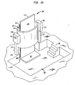
- FIG. 2A illustratively depicts a perspective view of a short bore magnet apparatus 160 in accordance with an aspect of the present invention.
- the apparatus 160 includes a short bore magnet 164 and a support structure 168.
- the magnet 164 is most preferably a superconducting solenoidal magnet and includes a bore 170.
- a patient support device 172 is supported by support structures 168, 168 and positionable within the bore 170.
- the support structure 178 also provides a housing and conduits for supporting power and cooling necessary to operate the magnet 164.
- wiring and piping may enter the support structure through the floor 175 at legs 177, 177 and be fed to the magnet 164 through the box 179 of the housing 168.
- the device 172 includes a footrest 182 for supporting the feet of a standing patient and a support surface 183 against which either the anterior or posterior surface of a patient's anatomy may be supported.
- the device 172 also includes a pair of slots 184 along its longitudinal edges 186. The slots 184 are used to translate the device into and out of the bore 170 of the magnet 164. As seen in FIG. 2A , the device 172 is disposed above a well 185, which may be entered by steps 186.
- a patient enters the well 185 via steps 186 while the device 172 is lowered to the floor 187 of the well 185. Once the patient is positioned on the footrest 182, the device 172 is raised, via gears housed in box 179, so that that portion of the patient's anatomy of interest may be imaged.
- the apparatus 160 allows the patient to be also imaged in any position between horizontal and vertical, and the Trendelenburg and reverse Trendelenburg positions by rotating the magnet 164 and device 172.
- the magnet 164 and device 172 are rotatably mounted to the support structure 168.
- a rod member 189 is mounted to gears 190, the device 172 and the magnet 174.
- the rod member 189 and gear 190 are coupled together in block 191 and are preferably electrically controlled and operated via cables 192, which extend downward to the floor.
- the rod member 189 is mounted into a sleeve 194 that rotates in unison with the rod 189.
- the rod member 189 terminates on the longitudinal edge of the device 172 in the slots 184.
- the end portion 193 of the rod member 189 disposed within slot 184 may include a larger cylindrical diameter than the rest of the rod, so that grooves 194 formed on the end portion 193 may reliably support, rotate and translate the device 172.
- the grooves 194 form pawls or fingers 195 that engage slots 196 on the device 172.
- translation of the device 172 relative to the bore 170 of the magnet 168 occurs when inner rod 198 (see FIG. 2D ), which may form a unitary structure with end portion 193, rotates within the rod member 189.
- inner rod 198 see FIG. 2D
- the inner rod 198 remains fixed relative to rod member 189 and the device 172 rotates via rod member 189 at end cap 199.
- the rotation of the magnet and device and translation of device are discussed in relation to one of the support structure 168, the same or similar rotational and translation means may be incorporated on the other support structure 168.
- the mechanism for rotation and translation may be implemented on either support structure or both support structures.
- other structures known in the art for similar functionality may be provided accordingly.
- a magnet 200 in accordance with the present invention includes a central cylindrical bore having a diameter, D, of approximately 45.7 cm (eighteen inches) or more.
- the length of the magnet, L, as measured along a cylindrical axis 204 is preferably approximately 91.4 cm (three feet).
- the diameter D of the magnet impacts the field strength and homogeneity of the static magnetic field that is produced when the magnet coils are energized.
- the diameter D of the magnet 200 may be as large as 91.4 cm (three feet) or more without sacrificing too much in the way of image acquisition by increasing the number of ampere-turns if necessary.
- the well depth and distance between the lower end 109 of the magnet and floor 134 is advantageously chosen to provide a comfortable clearance space between the lower end 109 of the magnet as the patient steps onto and off the foot rest 112.
- well 122 is approximately 91.4 cm (three feet) in depth and the magnet 104 is positioned such that its lower end 109 is approximately 91.4 cm (three feet) above the floor.
- an apparatus in accordance with the present invention, may require a floor 134 to ceiling clearance of approximately 2.74 cm (nine feet) for full body scanning.
- the floor 134 to ceiling clearance space requirement may be suitably lowered by increasing the well depth so that the apparatus may be housed in facilities that include less than nine feet of ceiling clearance space.
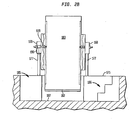
- FIG. 4 illustrates a magnetic resonance imaging apparatus 300 in accordance with an aspect of the present invention.
- the apparatus includes a magnet 304 preferably having a substantially cylindrical center bore 308, which is disposed in an opening 309 beneath a floor 310.
- the magnet 304 may be of the type discussed above in reference to FIGS. 1 , 2 and 3 .
- a patient support member 312 having a base member 314 and a wall 316 substantially transverse to the base member 314 is disposed in the bore 308.
- the patient support member 312 may be used as standing area for a patient.
- the patient support member 312 is mounted on an elevator 320.
- the elevator is used to lower and raise the patient support member 312 within the bore 308.
- the apparatus 300 is preferably disposed beneath the floor 310.
- the opening 310 for the magnet is contoured such that it completely hides the magnet 304.
- a patient may sit on the floor 310 with his or her leg hanging in the bore so that the patient's lower extremities may be imaged.
- the apparatus 300 may be used to image various portions of the lower extremities of a human anatomy, e.g., legs, ankle, knees, with the patient in both a standing and sitting position.
- the apparatus 300 may also be configured to image any portion of the human anatomy by allowing the elevator to recess further below the floor 310 into the magnet bore 308.
- the apparatus 300 may be used to image the torso of the anatomy.
- the head may also be imaged, in order to avoid creating feelings of anxiety and claustrophobia, it may be preferable to limit imaging in apparatus 300 to below the neck of a patient. Nonetheless, under the appropriate circumstances, the entire body, including the head of a patient, may be imaged using apparatus 300.
- auxiliary lighting may be employed to illuminate the magnet's bore space to make the scanning experience more comfortable.
- FIG. 5 Another aspect of the present invention is a facility for performing magnetic resonance imaging.
- the facility is equipped with a short bore vertical field magnet as described hereinabove and a short bore horizontal field magnet.
- a short bore horizontal field magnet may be constructed as illustrated in FIG. 5 .
- the apparatus 400 comprises a short bore magnet 404 having a horizontal field axis 408 that extends along a substantially horizontal direction.
- the magnet 404 includes a bore 412 into which may be placed a patient support 416.
- the magnet 404 may be of dimensions similar to those discussed hereinabove in relation to FIGS. 1 , 2 and 3 .
- the magnet 404 may include various support structures, similar to those disclosed in FIG.
- a facility equipped with both horizontal and vertical field short bores may advantageously increase the throughput of the facility.
- a facility that includes both a short bore horizontal field magnet 610 and a vertical field magnet 620 may advantageously increase the imaging throughout capability by allowing patients to be imaged in either apparatus.
- the magnet 620 would be designated for imaging where having the weight bearing position may yield more meaningful information.
- magnet 610 may be used.
- the apparatus of FIG. 4 may comprise the vertical field magnet.
- a variant in accordance with the present invention may include a magnet assembly comprising a plurality of coils arranged asymmetrical along an axis such that the center of a static magnetic field generated by the coils is offset from the center of the assembly as described, for example, in U.S. Patent No. 4,689,591 to McDougall .
- the coils are oriented to provide a static magnetic field having a field axis oriented in a substantially vertical direction as described above.
- a patient support device may then be appropriately equipped so as to raise or lower a patient into and out of the static magnetic field for imaging.
- a variant in accordance with the present invention may include replacement of either of the magnets 104, 160, 200, 304 or 400 with a pancake magnet of the type disclosed in U.S. Patent No. 5,428,292 to Dorri et al. ("the '292 patent").
- the '292 patent magnets may be stacked apart to provide a more open feeling to a patient being imaged.
- the magnets may be stacked vertically using assembly posts to provide an open magnetic resonance imaging system. The stacked magnets would then mounted to a support arm or structure and a patient could then be imaged in the bore created by the stacked magnets.
- the magnets 104, 160, 200, 304 or 400 may be replaced with magnet assemblies described in accordance with U.S. Patent Nos. 5,291,169 to Ige et al. ("the '169 patent") or 6,078,234 to Huang, et al. of "the '234 patent”).
- These magnet assemblies desirably comprise a separated pair of annular superconducting magnet assemblies in an open architecture.
- the magnets of the '169 or '234 patents may be turned on its end to provide a static magnetic field directed substantially in a vertical direction, thereby allowing a standing patient to be imaged within the bore of the magnet assembly.
Landscapes
- Health & Medical Sciences (AREA)
- Physics & Mathematics (AREA)
- Life Sciences & Earth Sciences (AREA)
- Nuclear Medicine, Radiotherapy & Molecular Imaging (AREA)
- Pathology (AREA)
- Heart & Thoracic Surgery (AREA)
- General Physics & Mathematics (AREA)
- Radiology & Medical Imaging (AREA)
- Condensed Matter Physics & Semiconductors (AREA)
- Biophysics (AREA)
- Veterinary Medicine (AREA)
- Engineering & Computer Science (AREA)
- Biomedical Technology (AREA)
- High Energy & Nuclear Physics (AREA)
- Medical Informatics (AREA)
- Molecular Biology (AREA)
- Surgery (AREA)
- Animal Behavior & Ethology (AREA)
- General Health & Medical Sciences (AREA)
- Public Health (AREA)
- Electromagnetism (AREA)
- Magnetic Resonance Imaging Apparatus (AREA)
Description
- The present invention relates to magnetic resonance imaging apparatus.
- In magnetic resonance imaging, an object to be imaged as, for example, a body of a human subject, is exposed to a strong, substantially constant static magnetic field. The static magnetic field causes the spin vectors of certain atomic nuclei within the body to randomly rotate or "precess" around an axis parallel to the direction of the static magnetic field. Radio frequency excitation energy is applied to the body, and this energy causes the nuclei to rotate or "precess" in phase and in an excited state. As the precessing atomic nuclei relax, weak radio frequency signals are emitted; such radio frequency signals are referred to herein as magnetic resonance signals.
- Different tissues produce different signal characteristics. Relaxation times are the dominant factor in determining signal strength. In addition, tissues having a high density of certain nuclei will produce stronger signals than tissues with a low density of such nuclei. Relatively small gradients in the magnetic field are superimposed on the static magnetic field at various times during the process so that magnetic resonance signals from different portions of the patient's body differ in phase and/or frequency. If the process is repeated numerous times using different combinations of gradients, the signals from the various repetitions together provide enough information to form a map of signal characteristics versus location within the body. Such a map can be reconstructed by conventional techniques well known in the magnetic resonance imaging art, and can be displayed as a pictorial image of the tissues as known in the art.
- The magnetic resonance imaging technique offers numerous advantages over other imaging techniques. MRI does not expose either the patient or medical personnel to X-rays and offers important safety advantages. Also, magnetic resonance imaging can obtain images of soft tissues and other features within the body which are not readily visualized using other imaging techniques. Accordingly, magnetic resonance imaging has been widely adopted in the medical and allied arts.
- Many conventional magnetic resonance imaging instruments require that a patient lie on a horizontal bed that is then advanced into a tubular bore within a super-conducting solenoidal magnet used to generate the static magnetic field. Other conventional MRI imaging instruments use a magnet having a ferromagnetic frame defining a patient-receiving space. Considerable effort has been devoted to the design of such magnets in a manner that provides a relatively open patient-receiving space as opposed to the claustrophobic tubular bore of the conventional solenoidal magnet. However, in these instruments as well, the common practice is to provide the patient on a bed that remains horizontal throughout the procedure.
- The position of a patient during magnetic resonance imaging may affect or limit the imaging information obtained. A patient may exhibit a symptom if oriented in an upright or weight bearing position and no symptom if oriented in a recumbent or horizontal position. For example, it may be necessary to image a patient in an upright or gravity bearing position to discern a symptom and provide a diagnosis for injuries relating to the neck, spine, hip, knee, foot or ankle areas of the human anatomy.
- Advancement in magnetic resonance imaging has resulted in imaging apparatus that supports a patient in any position between a vertical position and a horizontal position. As described in greater detail in certain embodiments of commonly assigned United States Patents Nos.
6,414,490 and6, 677, 753 , a magnetic resonance imaging system can be provided with a patient support, such as a table, which can extend in a generally vertical direction so that the long axis of the patient is substantially vertical. For example, the patient may be in a standing posture, with his back, side or front leaning against a generally vertical patient support. Such a support may include a footrest projecting from the table at its lower end and the patient may stand on the footrest. In other arrangements, the support includes a seat projecting from the table so that the seat is in a horizontal plane when the table surface is vertical. In particularly preferred arrangements, the patient support can move relative to the magnet. For example, the patient support may be arranged to move vertically relative to the magnet so as to elevate a portion of the patient into the patient-receiving space of the magnet. Alternatively or additionally, the patient support may be arranged to tilt through a range of orientations between a generally horizontal orientation and a generally vertical orientation. - The magnets used in the preferred embodiments of the aforementioned '490 and '753 patents typically are arranged so that the magnetic field is directed along a horizontal axis, transverse to the axis of elongation of the patient support and hence transverse to the long axis of the patient. By contrast, in a conventional solenoidal magnet where the patient is received inside the bore of the solenoid, the magnetic field is directed along the long axis of the patient.
U.S. Patent No. 5,349,956 , shows a theoretical proposal for a conventional solenoidal magnet having its axis orientated in a vertical direction, with a patient elevator arranged to raise a standing patient into the bore. In theory, such an arrangement could provide for imaging of a patient in an upright position. In practice, this arrangement is never used. One aspect of the present invention incorporates the realization that there are mechanical and safety difficulties inherent in this approach, together with problems presented by a terrifying and claustrophobic environment for the patient. - European patent application
0 067 933 discloses a magnetic resonance imaging apparatus comprising a magnet having a bore extending along a vertical axis and capable of generating a magnetic field parallel to the vertical axis. The patient may sit on a seat during MR examination. Alternatively, the patient may be examined standing upright. - A similar apparatus is known from
JP2001 104 276 - The present invention concern a magnetic resonance imaging apparatus comprising a magnet having a bore extending along a vertical axis and capable of generating a magnetic field parallel to the vertical axis; and a patient support device and means arranged to translate said patient support device in a direction parallel to the vertical axis so that a portion of the patient support device becomes situated in said magnet bore, wherein the length of said magnet along a direction parallel to the vertical axis is 1.22 m (four feet) or less, and said magnet and patient support are rotatable between an upright position wherein said magnetic field is parallel to said vertical axis and a recumbent position transverse to said vertical axis when said portion of the patient support device is situated in said magnet bore.
- In accordance with this aspect of the present invention, it is desirable that the apparatus also include a building structure housing said magnet and a magnet support structure connected to the building structure and connected to the magnet.
- Further in accordance with this aspect of the present invention, the building structure includes a floor and the magnet support is connected to the floor.
- Preferably, the magnet has an inner bore diameter of 91.4 cm (three feet) or more, however, an inner bore diameter of 45.7 cm (eighteen inches) or more is also suitable.
- In a preferred embodiment in accordance with this aspect of the invention, the magnet comprises a solenoidal magnet having turns encircling the bore and adapted to generate a static magnetic field having a field direction coaxial with said bore.
- In addition, it is desirable that the patient support be mounted to an elevator to raise and lower said patient support device if said magnet and patient support device are in the upright position.
- It may also be preferable to provide a support structure having one end connected to a floor and another end connected to the magnet and wherein the patient support device is mounted on an elevator to raise and lower said patient support device if said magnet and patient support device are in the upright position.
- Further in accordance with this aspect of the present invention, the magnet preferably has an inner bore diameter of 91.4 cm (three feet) or less.
- In another embodiment the magnet and patient support are positionable in either the Trendelberg or reverse Trendelburg positions.
-
-
FIG. 1 is a perspective view of a magnetic resonance imaging apparatus in accordance with an aspect of the present invention. -
FIG. 2A is a perspective view of a magnet resonance imaging apparatus in accordance with an aspect of the present invention. -
FIG. 2B is a front view of the magnet apparatus ofFIG. 2A . -
FIG. 2C is a partial exploded view of a portion of the magnet apparatus ofFIG. 2A . -
FIG. 2D illustratively depicts an embodiment of a portion of a rod member which can be used with the present invention. -
FIG. 3 is a perspective view of a short bore magnet which can be used in an apparatus in an apparatus of the present invention. -
FIG. 4 is a perspective view of a magnetic resonance imaging apparatus in accordance with an aspect of the present invention. -
FIG. 5 is a perspective view of a magnetic imaging apparatus in accordance with an aspect of the present invention. -
FIG. 6 is an illustrative schematic of a facility in accordance with an aspect of the present invention. -
FIG. 1 is a perspective view of a magneticresonance imaging apparatus 100 in accordance with an aspect of the present invention. Theapparatus 100 includes amagnet 104 having a substantially cylindricalcentral bore 106. Themagnet 104 is preferably an electromagnet and most preferably a superconducting solenoidal magnet. A patient support device or table 110 is positionable within thebore 106 and, as shown, may protrude through eachend magnet 104. As illustrated, thepatient support device 110 is capable of supporting a patient P in a standing position with the patient's head and feet being positioned outside the bore. Thepatient support device 110 may also be constructed so as to support a patient in a seated or sitting position. Thepatient support device 110 includes afootrest 112 at one end, which provides a standing surface for a patient. The patient support includes a distal orfree end 114 opposite thefootrest 112. When a patient is oriented in a standing position, the patient's head is located towards thefree end 114. The patient support may also include a seat (not shown) that allows a patient to sit while imaged. The patient support device may be made in accordance with the patient support device disclosed in pendingU.S. Patent Application Publication 2003/0204136 A1. filed on April 25, 2002 ;2004/0030241 A1 filed on may 1, 2003 which are assigned to assignee of the present invention. - As further illustrated in
FIG. 1 , thefootrest 112 of thepatient support device 110 is preferably attached or mounted on apedestal 116 of anelevator 118. Theelevator 118 is disposed within a well 122. Theelevator 118 includes ashaft member 124. Theshaft member 124 may comprise a plurality of co-centric cylindrical shaped members that recess into one another and anopening 128, e.g., telescoping. Alternatively, the shaft member may comprise a plurality of rectangular or square shaped members that recess into one another and into theopening 128. Although other arrangements for an elevator may be used, the use of shaft members wherein the rectangular or cylindrical shaped members recess into each other aids in minimizing the vertical space required beneath thewell floor 132. Preferably, theopening 128 for theshaft member 124 extends approximately 61 cm (two feet) beneath thefloor 132 of thewell 122. Access to thepatient support device 110 is provided by a series ofsteps 134 to an open area, well orpit 138. In a preferred embodiment, thefloor 132 of thearea 138 is at a depth of approximately 91.4 cm (3 feet) beneath thefloor 134. - The apparatus also includes a
support structure 140 for themagnet 104. As shown, thesupport structure 140 includes oneend 141 proximate thefloor 134. Thesupport structure 140 also includes aninner sidewall 142 and anouter sidewall 144. The inner andouter sidewalls end walls end wall 148 includes an opening through which is inserted arod member 150. As shown, an end of therod member 150 includes aflange 152 the overlaps theend wall 148 opening so as to keep therod member 150 in place. The other end (not shown) of therod member 150 is connected to themagnet 104. The arrangement of therod member 150 allows themagnet 104 to tilt relative to avertical axis 155. Accordingly, the apparatus preferably includes aspace 157 between theinner sidewall 142 and the rearward outer wall of themagnet 104. - In addition to acting as a support for the
magnet 104, thesupport structure 140 also serves as a housing through which the power supply and cooling flow necessary to operate a magnet may be fed to themagnet 104. Accordingly, theinner sidewall 142 may also include an opening through which cables and other conduits may be attached to themagnet 104. Where themagnet 104 is a superconducting magnet, a main magnet coil and a correction magnet coil may be wound within the interior ofmagnet structure 104. A cryocooler or other suitable cooling agent passes through conduits in thesupport structure 140 to cool both the main and correction magnet coils. In addition, suitable electrical connections may also be provided via the support structure to energize both the main coil and the correction coil and to provide a signal for controlling the tilt of themagnet 104. - The distance between the
lower end 109 and thefloor 134 is chosen so as to allow enough clearance space between thefree end 114 of thepatient support device 110 and thelower end 109 of themagnet 104 so that a patient can step onto thefoot rest 112 when theelevator 118 is at its lowest point without hitting their head against thelower end 109. Thus, preferably the distance between thewell floor 132 and thelower end 109 is at least 183 cm (six feet). Most preferably, thelower end 109 of themagnet 104 is suspended approximately 91.4 cm (three feet) above thefloor well floor 132. In such an arrangement, the length of thepatient support 110, as measured between thefootrest 112 and thefree end 114, is slightly less than 183 cm (six feet) so that the patient support sits entirely beneath thelower end 109 of the magnet when theelevator 118 is completely recessed within theopening 128. - The distance between the
lower end 109 of the magnet and thefloor 134 or the distance between thefloor 132 and the floor 134 (i.e., the well or pit depth) may be suitably arranged to allow for more room between thelower end 109 of the magnet and thefree end 114 of the patient support. For example, thelower end 109 of the magnet may be positioned approximately 122 cm (four feet) above thefloor 134 with a bit depth of three feet. Alternatively, thelower end 109 of the magnet may be positioned approximately 91.4 cm (three feet) above thefloor 134 with a "pit" depth of 122 cm (four feet). - In accordance with another aspect of the present invention, a patient can be imaged as follows. Initially, the
elevator 118 is adjusted to its lowest position such that the planar surface of thefootrest 112 is substantially parallel with thewell floor 132. A patient P enters the well orpit area 138 usingsteps 136 and proceeds to stand on thefootrest 112. Theelevator 118 is then raised and the patient enters thebore 106 headfirst. An operator then adjusts the height of theelevator 118 such that that portion of the patient's anatomy to be imaged will be appropriately positioned within the imaging volume of themagnet 104. Preferably, the coils of the magnet would have been previously energized (e.g., at the start of the day) to create a static magnetic field that is oriented substantially vertically and in a direction substantially parallel to thevertical axis 155, which is substantially parallel to the long axis of the patient. Imaging then proceeds as is known in the art. Once imaging is completed the elevator is lowered so that the planar surface of thefootrest 112 is again substantially parallel with thewell floor 132. The patient may then step offfootrest 112 and exit the pit orwell area 138. - As previously discussed, the
magnet 104 may include a mechanism that allows the magnet to tilt relative to thevertical axis 155. Thus, in some instances the imaging process may also include tilting the magnet and acquiring images of the patient with the magnet at an angle relative the patient. -
FIG. 2A illustratively depicts a perspective view of a shortbore magnet apparatus 160 in accordance with an aspect of the present invention. Theapparatus 160 includes ashort bore magnet 164 and asupport structure 168. Themagnet 164 is most preferably a superconducting solenoidal magnet and includes abore 170. Apatient support device 172 is supported bysupport structures bore 170. In addition to providing support to themagnet 164 anddevice 172, the support structure 178 also provides a housing and conduits for supporting power and cooling necessary to operate themagnet 164. Thus, wiring and piping may enter the support structure through thefloor 175 atlegs magnet 164 through thebox 179 of thehousing 168. - The
device 172 includes afootrest 182 for supporting the feet of a standing patient and asupport surface 183 against which either the anterior or posterior surface of a patient's anatomy may be supported. Thedevice 172 also includes a pair ofslots 184 along itslongitudinal edges 186. Theslots 184 are used to translate the device into and out of thebore 170 of themagnet 164. As seen inFIG. 2A , thedevice 172 is disposed above a well 185, which may be entered bysteps 186. - In operation, a patient enters the well 185 via
steps 186 while thedevice 172 is lowered to thefloor 187 of thewell 185. Once the patient is positioned on thefootrest 182, thedevice 172 is raised, via gears housed inbox 179, so that that portion of the patient's anatomy of interest may be imaged. - In addition to allowing for imaging in an upright position, the
apparatus 160 allows the patient to be also imaged in any position between horizontal and vertical, and the Trendelenburg and reverse Trendelenburg positions by rotating themagnet 164 anddevice 172. As best seen inFIG. 2B , themagnet 164 anddevice 172 are rotatably mounted to thesupport structure 168. In a preferred embodiment, arod member 189 is mounted togears 190, thedevice 172 and the magnet 174. - As best seen in
FIG. 2C , therod member 189 andgear 190 are coupled together inblock 191 and are preferably electrically controlled and operated via cables 192, which extend downward to the floor. In themagnet 170, therod member 189 is mounted into asleeve 194 that rotates in unison with therod 189. Therod member 189 terminates on the longitudinal edge of thedevice 172 in theslots 184. As shown, theend portion 193 of therod member 189 disposed withinslot 184 may include a larger cylindrical diameter than the rest of the rod, so thatgrooves 194 formed on theend portion 193 may reliably support, rotate and translate thedevice 172. - As best seen in
FIG. 2D , thegrooves 194 form pawls orfingers 195 that engageslots 196 on thedevice 172. In the embodiment shown, translation of thedevice 172 relative to thebore 170 of themagnet 168 occurs when inner rod 198 (seeFIG. 2D ), which may form a unitary structure withend portion 193, rotates within therod member 189. Thus, where rotation of themagnet 168 anddevice 172 is desired, theinner rod 198 remains fixed relative torod member 189 and thedevice 172 rotates viarod member 189 atend cap 199. - Although in the embodiment shown in
FIG. 2 , the rotation of the magnet and device and translation of device are discussed in relation to one of thesupport structure 168, the same or similar rotational and translation means may be incorporated on theother support structure 168. Thus, in a variant the mechanism for rotation and translation may be implemented on either support structure or both support structures. In some instances it may be preferable to have the rotational and translation means included only in a single support structure, while using the other support to provide any other ancillary functions, e.g., cable and conduit routing, necessary to operate the apparatus. In addition to the particular rotation and translation disclosures discussed above, other structures known in the art for similar functionality may be provided accordingly. - As best seen in
FIG. 3 , in a preferred embodiment amagnet 200 in accordance with the present invention includes a central cylindrical bore having a diameter, D, of approximately 45.7 cm (eighteen inches) or more. In addition, the length of the magnet, L, as measured along acylindrical axis 204 is preferably approximately 91.4 cm (three feet). The diameter D of the magnet impacts the field strength and homogeneity of the static magnetic field that is produced when the magnet coils are energized. Thus, as the internal diameter D is increased, the strength and homogeneity of the magnetic field within the bore may be affected. However, the diameter D of themagnet 200 may be as large as 91.4 cm (three feet) or more without sacrificing too much in the way of image acquisition by increasing the number of ampere-turns if necessary. - As discussed above, the well depth and distance between the
lower end 109 of the magnet andfloor 134 is advantageously chosen to provide a comfortable clearance space between thelower end 109 of the magnet as the patient steps onto and off thefoot rest 112. Thus, in a preferred embodiment well 122 is approximately 91.4 cm (three feet) in depth and themagnet 104 is positioned such that itslower end 109 is approximately 91.4 cm (three feet) above the floor. With a magnet having a length, L, of three feet, an apparatus, in accordance with the present invention, may require afloor 134 to ceiling clearance of approximately 2.74 cm (nine feet) for full body scanning. Thefloor 134 to ceiling clearance space requirement may be suitably lowered by increasing the well depth so that the apparatus may be housed in facilities that include less than nine feet of ceiling clearance space. -
FIG. 4 illustrates a magneticresonance imaging apparatus 300 in accordance with an aspect of the present invention. The apparatus includes amagnet 304 preferably having a substantially cylindrical center bore 308, which is disposed in anopening 309 beneath afloor 310. Themagnet 304 may be of the type discussed above in reference toFIGS. 1 ,2 and3 . Apatient support member 312 having abase member 314 and a wall 316 substantially transverse to thebase member 314 is disposed in thebore 308. Thepatient support member 312 may be used as standing area for a patient. Thepatient support member 312 is mounted on anelevator 320. The elevator is used to lower and raise thepatient support member 312 within thebore 308. As discussed, theapparatus 300 is preferably disposed beneath thefloor 310. Preferably, theopening 310 for the magnet is contoured such that it completely hides themagnet 304. In accordance with an aspect of the present invention, a patient may sit on thefloor 310 with his or her leg hanging in the bore so that the patient's lower extremities may be imaged. In accordance with this aspect of the present invention, theapparatus 300 may be used to image various portions of the lower extremities of a human anatomy, e.g., legs, ankle, knees, with the patient in both a standing and sitting position. - In addition to being configurable to image the lower extremities of a patient, the
apparatus 300 may also be configured to image any portion of the human anatomy by allowing the elevator to recess further below thefloor 310 into the magnet bore 308. Thus, theapparatus 300 may be used to image the torso of the anatomy. Although the head may also be imaged, in order to avoid creating feelings of anxiety and claustrophobia, it may be preferable to limit imaging inapparatus 300 to below the neck of a patient. Nonetheless, under the appropriate circumstances, the entire body, including the head of a patient, may be imaged usingapparatus 300. - It may also be advantageous, from a patient's perspective, to house the
apparatus 300 beneath the floor such that it is concealed from the patient. In such an embodiment, auxiliary lighting may be employed to illuminate the magnet's bore space to make the scanning experience more comfortable. - Another aspect of the present invention is a facility for performing magnetic resonance imaging. In accordance with this aspect of the invention, the facility is equipped with a short bore vertical field magnet as described hereinabove and a short bore horizontal field magnet. In accordance with this aspect of the present invention, a short bore horizontal field magnet may be constructed as illustrated in
FIG. 5 . Theapparatus 400 comprises ashort bore magnet 404 having ahorizontal field axis 408 that extends along a substantially horizontal direction. Themagnet 404 includes abore 412 into which may be placed apatient support 416. Themagnet 404 may be of dimensions similar to those discussed hereinabove in relation toFIGS. 1 ,2 and3 . Although not shown, themagnet 404 may include various support structures, similar to those disclosed inFIG. 1 , to hold the magnet in place. In addition, various arrangements are available for translating thepatient support 416 parallel to thehorizontal field axis 408. A facility equipped with both horizontal and vertical field short bores may advantageously increase the throughput of the facility. In particular, and as shown inFIG. 6 , a facility that includes both a short borehorizontal field magnet 610 and avertical field magnet 620 may advantageously increase the imaging throughout capability by allowing patients to be imaged in either apparatus. Advantageously, themagnet 620 would be designated for imaging where having the weight bearing position may yield more meaningful information. Alternatively, where it is acceptable that imaging be performed in a horizontal position,magnet 610 may be used. Furthermore, although themagnet 620 is shown as being positioned above the floor as inFIGS. 1 or3 , the apparatus ofFIG. 4 may comprise the vertical field magnet. - A variant in accordance with the present invention may include a magnet assembly comprising a plurality of coils arranged asymmetrical along an axis such that the center of a static magnetic field generated by the coils is offset from the center of the assembly as described, for example, in
U.S. Patent No. 4,689,591 to McDougall . In accordance with this aspect of the present invention, the coils are oriented to provide a static magnetic field having a field axis oriented in a substantially vertical direction as described above. A patient support device may then be appropriately equipped so as to raise or lower a patient into and out of the static magnetic field for imaging. - A variant in accordance with the present invention may include replacement of either of the
magnets U.S. Patent No. 5,428,292 to Dorri et al. ("the '292 patent"). Further in accordance with this aspect of the present invention, one or more of the '292 patent magnets may be stacked apart to provide a more open feeling to a patient being imaged. Thus, the magnets may be stacked vertically using assembly posts to provide an open magnetic resonance imaging system. The stacked magnets would then mounted to a support arm or structure and a patient could then be imaged in the bore created by the stacked magnets. In another variant in accordance with the present invention themagnets U.S. Patent Nos. 5,291,169 to Ige et al. ("the '169 patent") or6,078,234 to Huang, et al. of "the '234 patent"). These magnet assemblies desirably comprise a separated pair of annular superconducting magnet assemblies in an open architecture. In accordance with an aspect of the present invention, the magnets of the '169 or '234 patents may be turned on its end to provide a static magnetic field directed substantially in a vertical direction, thereby allowing a standing patient to be imaged within the bore of the magnet assembly. - Although the invention herein has been described with reference to particular embodiments, it is to be understood that these embodiments are merely illustrative of the principles and applications of the present invention. For example, other magnet assemblies such as that described in
U.S. Patent No. 4,721,914 to Fukushima et al. may be applied or used in accordance with the present invention. It is therefore to be understood that numerous modifications may be made to the illustrative embodiments and that other arrangements may be devised without departing from the scope of the present invention as defined by the appended claims.
Claims (11)
- A magnetic resonance imaging apparatus (100, 160, 300, 400), comprising:a magnet (104, 164, 200, 304, 404) having a bore extending along a vertical axis and capable of generating a magnetic field parallel to the vertical axis; anda patient support device (110, 172, 416) and means arranged to translate said patient support device in a direction parallel to the vertical axis so that a portion of the patient support device becomes situated in said magnet bore,wherein the length of said magnet (104, 164, 200, 304, 404) along a direction parallel to the vertical axis is 1.22 m (four feet) or less, andsaid magnet and patient support are rotatable between an upright position wherein said magnetic field is parallel to said vertical axis and a recumbent position transverse to said vertical axis, when said portion of the patient support device is situated in said magnet bove.
- The apparatus of claim 1, further comprising a building structure housing said magnet (104, 164, 200, 304, 404) and a magnet support structure (140, 168, 178) connected to said building structure and said magnet.
- The apparatus of claim 2, wherein said building structure includes a floor (134) and said magnet support is connected to said floor.
- The apparatus of claim 1, wherein said magnet (104, 164, 200, 304, 404) has an inner bore diameter of 45.7 cm (eighteen inches) or more.
- The apparatus of claim 4, wherein said magnet (104, 164, 200, 304, 404) has an inner bore diameter of 91.4 cm (three feet) or more.
- The apparatus of claim 1, wherein said magnet (104, 164, 200, 304, 404) comprises a solenoidal magnet having turns encircling said bore and adapted to generate a static magnetic field having a field direction coaxial with said bore.
- The apparatus of claim 1, further comprising an elevator (320) on which said patient support device is mounted if said magnet and patient support are in the upright position, said elevator being arranged to raise and lower said patient support device.
- The apparatus of claim 1, further comprising a support structure having one end to be supported by a floor and another end connected to said magnet, the apparatus comprising elevator on which said patient support device is mounted if said magnet and patient support are in the upright position.
- The apparatus of claim 1, wherein the length of said magnet along a direction parallel to the vertical axis is less than 91.4 cm (three feet).
- The apparatus of claim 1, wherein said magnet and patient support are positionable in a Trendelenburg position.
- The apparatus of claim 10, wherein said magnet and patient support are positionable in a reverse Trendelenburg position.
Applications Claiming Priority (2)
| Application Number | Priority Date | Filing Date | Title |
|---|---|---|---|
| US52602903P | 2003-12-01 | 2003-12-01 | |
| PCT/US2004/040104 WO2005053515A2 (en) | 2003-12-01 | 2004-12-01 | Stand-up vertical field mri apparatus |
Publications (3)
| Publication Number | Publication Date |
|---|---|
| EP1689286A2 EP1689286A2 (en) | 2006-08-16 |
| EP1689286A4 EP1689286A4 (en) | 2009-03-04 |
| EP1689286B1 true EP1689286B1 (en) | 2013-01-09 |
Family
ID=34652410
Family Applications (1)
| Application Number | Title | Priority Date | Filing Date |
|---|---|---|---|
| EP04812587A Expired - Lifetime EP1689286B1 (en) | 2003-12-01 | 2004-12-01 | Stand-up vertical field mri apparatus |
Country Status (2)
| Country | Link |
|---|---|
| EP (1) | EP1689286B1 (en) |
| WO (1) | WO2005053515A2 (en) |
Families Citing this family (2)
| Publication number | Priority date | Publication date | Assignee | Title |
|---|---|---|---|---|
| TW202015621A (en) * | 2018-07-19 | 2020-05-01 | 美商超精細研究股份有限公司 | Method and equipment for positioning patients in magnetic resonance imaging |
| CN114487955A (en) * | 2020-11-13 | 2022-05-13 | 首都医科大学附属北京朝阳医院 | Vertical nuclear magnetic resonance device |
Family Cites Families (8)
| Publication number | Priority date | Publication date | Assignee | Title |
|---|---|---|---|---|
| DE3123493A1 (en) * | 1981-06-13 | 1982-12-30 | Bruker Analytische Meßtechnik GmbH, 7512 Rheinstetten | ELECTROMAGNET FOR NMR TOMOGRAPHY |
| JPH01305937A (en) * | 1988-06-02 | 1989-12-11 | Toshiba Corp | Magnetic resonance diagnosis device |
| US4924198A (en) * | 1988-07-05 | 1990-05-08 | General Electric Company | Superconductive magnetic resonance magnet without cryogens |
| GB9206014D0 (en) * | 1992-03-19 | 1992-04-29 | Oxford Instr Ltd | Magnet assembly |
| US5382904A (en) * | 1992-04-15 | 1995-01-17 | Houston Advanced Research Center | Structured coil electromagnets for magnetic resonance imaging and method for fabricating the same |
| US6023165A (en) * | 1992-09-28 | 2000-02-08 | Fonar Corporation | Nuclear magnetic resonance apparatus and methods of use and facilities for incorporating the same |
| JP4149626B2 (en) * | 1999-10-06 | 2008-09-10 | ジーイー横河メディカルシステム株式会社 | MRI equipment |
| GB0007018D0 (en) * | 2000-03-22 | 2000-05-10 | Akguen Ali | Magnetic resonance imaging apparatus and method |
-
2004
- 2004-12-01 EP EP04812587A patent/EP1689286B1/en not_active Expired - Lifetime
- 2004-12-01 WO PCT/US2004/040104 patent/WO2005053515A2/en not_active Ceased
Also Published As
| Publication number | Publication date |
|---|---|
| EP1689286A4 (en) | 2009-03-04 |
| WO2005053515A3 (en) | 2006-12-07 |
| WO2005053515A2 (en) | 2005-06-16 |
| EP1689286A2 (en) | 2006-08-16 |
Similar Documents
| Publication | Publication Date | Title |
|---|---|---|
| US7196519B2 (en) | Stand-up vertical field MRI apparatus | |
| US6507192B1 (en) | Nuclear magnetic resonance apparatus and methods of use and facilities for incorporating the same | |
| US9714992B2 (en) | Versatile superconducting magnet for extremities magnetic resonance imaging | |
| US6828792B1 (en) | MRI apparatus and method for imaging | |
| EP0927889B1 (en) | Adjustable interventional magnetic resonance imaging magnet | |
| US6541973B1 (en) | MRI apparatus | |
| US20020123681A1 (en) | Device and a system for moving and positioning an open magnetic resonance imaging probe | |
| US20180011153A1 (en) | Magnetic resonance imaging (mri) system with adjustable bore orientation | |
| US7680525B1 (en) | Method for lateral motion magnetic resonance imaging | |
| US7812607B2 (en) | Magnetic resonance imaging system, apparatus and associated methods | |
| US8055325B1 (en) | Seated patient support and use thereof in magnetic resonance imaging | |
| JPH07143975A (en) | Magnetic resonance picture device | |
| US11852703B2 (en) | Magnetic resonance imaging device with a concave-shaped field generation unit | |
| EP1689286B1 (en) | Stand-up vertical field mri apparatus | |
| US7525312B2 (en) | System for magnetic resonance imaging assisted surgery | |
| EP1978372A2 (en) | MRI apparatus and MRI method using such apparatus | |
| US7102353B1 (en) | Magnetic resonance imaging apparatus having moving magnets | |
| US7030612B1 (en) | Body rest for magnetic resonance imaging | |
| US8401615B1 (en) | Planar coil flexion fixture for magnetic resonance imaging and use thereof | |
| US7378846B1 (en) | Magnetic resonance imaging method and apparatus for scanning a child | |
| WO2014138293A1 (en) | Versatile superconducting magnet for extremities magnetic resonance imaging | |
| CN120959767A (en) | Medical imaging equipment with patient support device | |
| CN120514569A (en) | Patient chairs and MRI equipment | |
| JP2003204950A (en) | MRI equipment |
Legal Events
| Date | Code | Title | Description |
|---|---|---|---|
| PUAI | Public reference made under article 153(3) epc to a published international application that has entered the european phase |
Free format text: ORIGINAL CODE: 0009012 |
|
| 17P | Request for examination filed |
Effective date: 20060522 |
|
| AK | Designated contracting states |
Kind code of ref document: A2 Designated state(s): AT BE BG CH CY CZ DE DK EE ES FI FR GB GR HU IE IS IT LI LT LU MC NL PL PT RO SE SI SK TR |
|
| AX | Request for extension of the european patent |
Extension state: AL BA HR LV MK YU |
|
| PUAK | Availability of information related to the publication of the international search report |
Free format text: ORIGINAL CODE: 0009015 |
|
| RIC1 | Information provided on ipc code assigned before grant |
Ipc: G01V 3/00 20060101AFI20070116BHEP |
|
| DAX | Request for extension of the european patent (deleted) | ||
| A4 | Supplementary search report drawn up and despatched |
Effective date: 20090130 |
|
| 17Q | First examination report despatched |
Effective date: 20100607 |
|
| REG | Reference to a national code |
Ref country code: DE Ref legal event code: R079 Ref document number: 602004040756 Country of ref document: DE Free format text: PREVIOUS MAIN CLASS: A61B0001000000 Ipc: A61B0005055000 |
|
| GRAP | Despatch of communication of intention to grant a patent |
Free format text: ORIGINAL CODE: EPIDOSNIGR1 |
|
| RIC1 | Information provided on ipc code assigned before grant |
Ipc: G01R 33/30 20060101ALI20120511BHEP Ipc: G01R 33/381 20060101ALI20120511BHEP Ipc: A61B 5/055 20060101AFI20120511BHEP |
|
| GRAS | Grant fee paid |
Free format text: ORIGINAL CODE: EPIDOSNIGR3 |
|
| GRAP | Despatch of communication of intention to grant a patent |
Free format text: ORIGINAL CODE: EPIDOSNIGR1 |
|
| GRAA | (expected) grant |
Free format text: ORIGINAL CODE: 0009210 |
|
| AK | Designated contracting states |
Kind code of ref document: B1 Designated state(s): AT BE BG CH CY CZ DE DK EE ES FI FR GB GR HU IE IS IT LI LT LU MC NL PL PT RO SE SI SK TR |
|
| REG | Reference to a national code |
Ref country code: GB Ref legal event code: FG4D |
|
| REG | Reference to a national code |
Ref country code: CH Ref legal event code: EP Ref country code: AT Ref legal event code: REF Ref document number: 592271 Country of ref document: AT Kind code of ref document: T Effective date: 20130115 |
|
| REG | Reference to a national code |
Ref country code: IE Ref legal event code: FG4D |
|
| REG | Reference to a national code |
Ref country code: DE Ref legal event code: R096 Ref document number: 602004040756 Country of ref document: DE Effective date: 20130307 |
|
| REG | Reference to a national code |
Ref country code: NL Ref legal event code: T3 |
|
| PG25 | Lapsed in a contracting state [announced via postgrant information from national office to epo] |
Ref country code: SI Free format text: LAPSE BECAUSE OF FAILURE TO SUBMIT A TRANSLATION OF THE DESCRIPTION OR TO PAY THE FEE WITHIN THE PRESCRIBED TIME-LIMIT Effective date: 20130109 |
|
| REG | Reference to a national code |
Ref country code: AT Ref legal event code: MK05 Ref document number: 592271 Country of ref document: AT Kind code of ref document: T Effective date: 20130109 |
|
| REG | Reference to a national code |
Ref country code: LT Ref legal event code: MG4D |
|
| PG25 | Lapsed in a contracting state [announced via postgrant information from national office to epo] |
Ref country code: BE Free format text: LAPSE BECAUSE OF FAILURE TO SUBMIT A TRANSLATION OF THE DESCRIPTION OR TO PAY THE FEE WITHIN THE PRESCRIBED TIME-LIMIT Effective date: 20130109 Ref country code: LT Free format text: LAPSE BECAUSE OF FAILURE TO SUBMIT A TRANSLATION OF THE DESCRIPTION OR TO PAY THE FEE WITHIN THE PRESCRIBED TIME-LIMIT Effective date: 20130109 Ref country code: CY Free format text: LAPSE BECAUSE OF FAILURE TO SUBMIT A TRANSLATION OF THE DESCRIPTION OR TO PAY THE FEE WITHIN THE PRESCRIBED TIME-LIMIT Effective date: 20130109 Ref country code: SE Free format text: LAPSE BECAUSE OF FAILURE TO SUBMIT A TRANSLATION OF THE DESCRIPTION OR TO PAY THE FEE WITHIN THE PRESCRIBED TIME-LIMIT Effective date: 20130109 Ref country code: BG Free format text: LAPSE BECAUSE OF FAILURE TO SUBMIT A TRANSLATION OF THE DESCRIPTION OR TO PAY THE FEE WITHIN THE PRESCRIBED TIME-LIMIT Effective date: 20130409 Ref country code: IS Free format text: LAPSE BECAUSE OF FAILURE TO SUBMIT A TRANSLATION OF THE DESCRIPTION OR TO PAY THE FEE WITHIN THE PRESCRIBED TIME-LIMIT Effective date: 20130509 Ref country code: ES Free format text: LAPSE BECAUSE OF FAILURE TO SUBMIT A TRANSLATION OF THE DESCRIPTION OR TO PAY THE FEE WITHIN THE PRESCRIBED TIME-LIMIT Effective date: 20130420 Ref country code: AT Free format text: LAPSE BECAUSE OF FAILURE TO SUBMIT A TRANSLATION OF THE DESCRIPTION OR TO PAY THE FEE WITHIN THE PRESCRIBED TIME-LIMIT Effective date: 20130109 |
|
| PG25 | Lapsed in a contracting state [announced via postgrant information from national office to epo] |
Ref country code: FI Free format text: LAPSE BECAUSE OF FAILURE TO SUBMIT A TRANSLATION OF THE DESCRIPTION OR TO PAY THE FEE WITHIN THE PRESCRIBED TIME-LIMIT Effective date: 20130109 Ref country code: GR Free format text: LAPSE BECAUSE OF FAILURE TO SUBMIT A TRANSLATION OF THE DESCRIPTION OR TO PAY THE FEE WITHIN THE PRESCRIBED TIME-LIMIT Effective date: 20130410 Ref country code: PT Free format text: LAPSE BECAUSE OF FAILURE TO SUBMIT A TRANSLATION OF THE DESCRIPTION OR TO PAY THE FEE WITHIN THE PRESCRIBED TIME-LIMIT Effective date: 20130509 Ref country code: PL Free format text: LAPSE BECAUSE OF FAILURE TO SUBMIT A TRANSLATION OF THE DESCRIPTION OR TO PAY THE FEE WITHIN THE PRESCRIBED TIME-LIMIT Effective date: 20130109 |
|
| PG25 | Lapsed in a contracting state [announced via postgrant information from national office to epo] |
Ref country code: DK Free format text: LAPSE BECAUSE OF FAILURE TO SUBMIT A TRANSLATION OF THE DESCRIPTION OR TO PAY THE FEE WITHIN THE PRESCRIBED TIME-LIMIT Effective date: 20130109 Ref country code: RO Free format text: LAPSE BECAUSE OF FAILURE TO SUBMIT A TRANSLATION OF THE DESCRIPTION OR TO PAY THE FEE WITHIN THE PRESCRIBED TIME-LIMIT Effective date: 20130109 Ref country code: SK Free format text: LAPSE BECAUSE OF FAILURE TO SUBMIT A TRANSLATION OF THE DESCRIPTION OR TO PAY THE FEE WITHIN THE PRESCRIBED TIME-LIMIT Effective date: 20130109 Ref country code: CZ Free format text: LAPSE BECAUSE OF FAILURE TO SUBMIT A TRANSLATION OF THE DESCRIPTION OR TO PAY THE FEE WITHIN THE PRESCRIBED TIME-LIMIT Effective date: 20130109 Ref country code: EE Free format text: LAPSE BECAUSE OF FAILURE TO SUBMIT A TRANSLATION OF THE DESCRIPTION OR TO PAY THE FEE WITHIN THE PRESCRIBED TIME-LIMIT Effective date: 20130109 |
|
| PLBE | No opposition filed within time limit |
Free format text: ORIGINAL CODE: 0009261 |
|
| STAA | Information on the status of an ep patent application or granted ep patent |
Free format text: STATUS: NO OPPOSITION FILED WITHIN TIME LIMIT |
|
| 26N | No opposition filed |
Effective date: 20131010 |
|
| REG | Reference to a national code |
Ref country code: DE Ref legal event code: R097 Ref document number: 602004040756 Country of ref document: DE Effective date: 20131010 |
|
| PG25 | Lapsed in a contracting state [announced via postgrant information from national office to epo] |
Ref country code: MC Free format text: LAPSE BECAUSE OF FAILURE TO SUBMIT A TRANSLATION OF THE DESCRIPTION OR TO PAY THE FEE WITHIN THE PRESCRIBED TIME-LIMIT Effective date: 20130109 |
|
| REG | Reference to a national code |
Ref country code: CH Ref legal event code: PL |
|
| PG25 | Lapsed in a contracting state [announced via postgrant information from national office to epo] |
Ref country code: LU Free format text: LAPSE BECAUSE OF FAILURE TO SUBMIT A TRANSLATION OF THE DESCRIPTION OR TO PAY THE FEE WITHIN THE PRESCRIBED TIME-LIMIT Effective date: 20131201 |
|
| REG | Reference to a national code |
Ref country code: IE Ref legal event code: MM4A |
|
| PG25 | Lapsed in a contracting state [announced via postgrant information from national office to epo] |
Ref country code: LI Free format text: LAPSE BECAUSE OF NON-PAYMENT OF DUE FEES Effective date: 20131231 Ref country code: CH Free format text: LAPSE BECAUSE OF NON-PAYMENT OF DUE FEES Effective date: 20131231 Ref country code: IE Free format text: LAPSE BECAUSE OF NON-PAYMENT OF DUE FEES Effective date: 20131201 |
|
| PG25 | Lapsed in a contracting state [announced via postgrant information from national office to epo] |
Ref country code: TR Free format text: LAPSE BECAUSE OF FAILURE TO SUBMIT A TRANSLATION OF THE DESCRIPTION OR TO PAY THE FEE WITHIN THE PRESCRIBED TIME-LIMIT Effective date: 20130109 |
|
| PG25 | Lapsed in a contracting state [announced via postgrant information from national office to epo] |
Ref country code: HU Free format text: LAPSE BECAUSE OF FAILURE TO SUBMIT A TRANSLATION OF THE DESCRIPTION OR TO PAY THE FEE WITHIN THE PRESCRIBED TIME-LIMIT; INVALID AB INITIO Effective date: 20041201 |
|
| REG | Reference to a national code |
Ref country code: FR Ref legal event code: PLFP Year of fee payment: 12 |
|
| REG | Reference to a national code |
Ref country code: FR Ref legal event code: PLFP Year of fee payment: 13 |
|
| PG25 | Lapsed in a contracting state [announced via postgrant information from national office to epo] |
Ref country code: IT Free format text: LAPSE BECAUSE OF NON-PAYMENT OF DUE FEES Effective date: 20151201 |
|
| PG25 | Lapsed in a contracting state [announced via postgrant information from national office to epo] |
Ref country code: IT Free format text: LAPSE BECAUSE OF NON-PAYMENT OF DUE FEES Effective date: 20151201 |
|
| PGRI | Patent reinstated in contracting state [announced from national office to epo] |
Ref country code: IT Effective date: 20170710 |
|
| REG | Reference to a national code |
Ref country code: FR Ref legal event code: PLFP Year of fee payment: 14 |
|
| REG | Reference to a national code |
Ref country code: DE Ref legal event code: R082 Ref document number: 602004040756 Country of ref document: DE Representative=s name: ZACCO LEGAL RECHTSANWALTSGESELLSCHAFT MBH, DE |
|
| PGFP | Annual fee paid to national office [announced via postgrant information from national office to epo] |
Ref country code: GB Payment date: 20231227 Year of fee payment: 20 |
|
| PGFP | Annual fee paid to national office [announced via postgrant information from national office to epo] |
Ref country code: NL Payment date: 20231226 Year of fee payment: 20 Ref country code: IT Payment date: 20231220 Year of fee payment: 20 Ref country code: FR Payment date: 20231227 Year of fee payment: 20 |
|
| PGFP | Annual fee paid to national office [announced via postgrant information from national office to epo] |
Ref country code: DE Payment date: 20231229 Year of fee payment: 20 |
|
| REG | Reference to a national code |
Ref country code: DE Ref legal event code: R071 Ref document number: 602004040756 Country of ref document: DE |
|
| REG | Reference to a national code |
Ref country code: NL Ref legal event code: MK Effective date: 20241130 |
|
| REG | Reference to a national code |
Ref country code: GB Ref legal event code: PE20 Expiry date: 20241130 |
|
| PG25 | Lapsed in a contracting state [announced via postgrant information from national office to epo] |
Ref country code: GB Free format text: LAPSE BECAUSE OF EXPIRATION OF PROTECTION Effective date: 20241130 |
|
| PG25 | Lapsed in a contracting state [announced via postgrant information from national office to epo] |
Ref country code: GB Free format text: LAPSE BECAUSE OF EXPIRATION OF PROTECTION Effective date: 20241130 |