EP1689218A2 - Frame part of installation casing - Google Patents
Frame part of installation casing Download PDFInfo
- Publication number
- EP1689218A2 EP1689218A2 EP06101081A EP06101081A EP1689218A2 EP 1689218 A2 EP1689218 A2 EP 1689218A2 EP 06101081 A EP06101081 A EP 06101081A EP 06101081 A EP06101081 A EP 06101081A EP 1689218 A2 EP1689218 A2 EP 1689218A2
- Authority
- EP
- European Patent Office
- Prior art keywords
- frame plate
- installation panel
- dents
- installation
- frame
- Prior art date
- Legal status (The legal status is an assumption and is not a legal conclusion. Google has not performed a legal analysis and makes no representation as to the accuracy of the status listed.)
- Granted
Links
- 238000009434 installation Methods 0.000 title claims abstract description 70
- 238000000034 method Methods 0.000 claims description 6
- 238000005304 joining Methods 0.000 claims description 3
- 238000004519 manufacturing process Methods 0.000 claims description 3
- 238000007493 shaping process Methods 0.000 claims 2
- 238000005452 bending Methods 0.000 claims 1
- 238000013016 damping Methods 0.000 description 11
- 239000000463 material Substances 0.000 description 6
- 238000001816 cooling Methods 0.000 description 5
- 238000009423 ventilation Methods 0.000 description 3
- 239000002184 metal Substances 0.000 description 2
- 238000003825 pressing Methods 0.000 description 2
- 238000004026 adhesive bonding Methods 0.000 description 1
- 238000005260 corrosion Methods 0.000 description 1
- 230000007797 corrosion Effects 0.000 description 1
- 230000001419 dependent effect Effects 0.000 description 1
- 238000012986 modification Methods 0.000 description 1
- 230000004048 modification Effects 0.000 description 1
- 239000002245 particle Substances 0.000 description 1
- 238000003466 welding Methods 0.000 description 1
Images

Classifications
-
- H—ELECTRICITY
- H05—ELECTRIC TECHNIQUES NOT OTHERWISE PROVIDED FOR
- H05K—PRINTED CIRCUITS; CASINGS OR CONSTRUCTIONAL DETAILS OF ELECTRIC APPARATUS; MANUFACTURE OF ASSEMBLAGES OF ELECTRICAL COMPONENTS
- H05K7/00—Constructional details common to different types of electric apparatus
- H05K7/18—Construction of rack or frame
-
- H—ELECTRICITY
- H05—ELECTRIC TECHNIQUES NOT OTHERWISE PROVIDED FOR
- H05K—PRINTED CIRCUITS; CASINGS OR CONSTRUCTIONAL DETAILS OF ELECTRIC APPARATUS; MANUFACTURE OF ASSEMBLAGES OF ELECTRICAL COMPONENTS
- H05K5/00—Casings, cabinets or drawers for electric apparatus
- H05K5/04—Metal casings
-
- H—ELECTRICITY
- H05—ELECTRIC TECHNIQUES NOT OTHERWISE PROVIDED FOR
- H05K—PRINTED CIRCUITS; CASINGS OR CONSTRUCTIONAL DETAILS OF ELECTRIC APPARATUS; MANUFACTURE OF ASSEMBLAGES OF ELECTRICAL COMPONENTS
- H05K7/00—Constructional details common to different types of electric apparatus
- H05K7/14—Mounting supporting structure in casing or on frame or rack
- H05K7/1422—Printed circuit boards receptacles, e.g. stacked structures, electronic circuit modules or box like frames
- H05K7/1427—Housings
- H05K7/1432—Housings specially adapted for power drive units or power converters
Definitions
- the present invention relates to a frame part of an installation casing, with the help of which any equipment installed in the installation casing can be protected from external vibration and impacts.
- installation casing should be understood widely to cover installation casings or cabinets of different type and size, into which components to be protected from vibration can be arranged.
- Prior-art solutions exist, in which vibration protection for devices installed in an installation casing is provided by utilizing a layered structure.
- a separate damping layer is arranged between an installation panel and frame plate.
- the damping layer is made of a material or designed in such a manner that it does not allow external vibration acting on the frame plate to transmit to the devices installed on the installation panel.
- the invention utilizes dents formed in the installation panel or frame plate or both.
- the number, location, and shape of the dents affect the damping properties so as to provide exactly the right damping for the application.
- the installation panel and frame plate comprise an angle, on both sides of which the installation panel and frame plate are fastened to each other through dents.
- the structure becomes more rigid than before.
- one preferred embodiment uses perforation in the area of the dents to provide a structure that enables efficient cooling. In such a case, it is namely possible to provide an airflow in the space between the installation panel and frame plate on both sides of the above-mentioned angle.
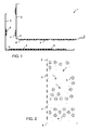
- Figures 1 and 2 illustrate the assembly of a frame part of the invention.
- the frame part 1 is assembled from an installation panel 2 and a frame plate 3.
- Figure 1 shows the installation panel 2 and frame plate 3 before they are attached to each other, and
- Figure 2 shows the side of the installation panel 2 that faces the inside of the installation casing.
- the metal installation panel 2 of the frame part 1 is made of an even plate in such a manner that the areas where dents will be formed are first perforated through the panel. After this, the dents 4 are formed into the panel by pressing. The dents 4 of the installation panel 2 are formed in such a manner that in a finished frame part, they protrude into the space between the installation panel 2 and frame plate 3. Finally, the installation panel 2 is bent to form an angle 5.
- the metal frame plate 3 of the frame part 1 is made in the same manner as the installation panel.
- the dents in the frame plate 3 are formed in such a manner that in a finished frame part, they protrude into the space between the installation panel 2 and frame plate 3.
- a finished frame plate 3 and installation panel 2 are set against each other in the position illustrated in Figure 1. After this, the panel and plate are fastened to each other through the dents 4.
- the dents are mainly conical in shape, i.e. only their ends are flat where they come into contact with the opposite plate. Such dents can be formed in a plate by pressing.
- Figure 3 shows a preferred embodiment of a frame part 1 of the invention.
- the frame plate 3 and installation panel 2 are fastened to each other at the dents.
- the fastening is preferably done by intangible riveting, in which a notch is hit through one of the plates with a sharp object so that the plate material displaced by the sharp object is pressed through the counterpart plate to form a rivet 8 between the plates.
- Intangible riveting provides the advantage that the frame part 1 is inexpensive and quick to assemble and that for instance the corrosion risk caused by different material pairs can be avoided, because a separate rivet material is not necessary for the joining.
- the frame plate 3 and installation panel can also be attached to each other in some other manner, for example by screwing, welding, gluing, or by using a separate rivet.
- the frame part 1 is shown installed in place into the installation casing shown from the top.
- the frame part 1 and the attached plates 9 thus form the walls of the installation casing that enclose the devices to be installed into the installation casing.
- the device to be installed are fastened to fastening pins 6 protruding from the installation panel 2.
- the frame plate 3 is fastened to the surrounding structure in such a manner, for instance, that it stands on the base of the installation casing. Because the installation panel 2 is fastened to the frame plate 3 through dents 4 only, vibration protection is achieved with the dents for the devices fastened to the fastening pints 6. The efficiency of the vibration protection depends on the shape and perforation of the dents and the thickness of the used plate.
- the dents 4 are staggered on the installation panel 2 and frame plate 3.
- An alternative is that the dents in the installation panel 2 and frame plate 3 are at the same locations, whereby the dents of different plates settle opposite each other in contact with each other. The distance between the installation panel 2 and frame plate 3 then doubles, and the space 7 becomes wider. This affects the vibration damping properties of the frame part 1 and the volume of air fitting into the space 7.
- the dents 4 are perforated. This is especially advantageous when devices requiring cooling are installed in the installation casing in question.
- the installation casing of a frequency converter is one example of a case in which efficient cooling is desirable.
- a fan can then be installed into the installation casing to provide airflow therein. The air can then flow through the perforations in the dents to the space 7 and out of the installation casing.
- the frame plate 3 forms the cooling element.
- filter material for instance, can be mounted between the installation panel 2 and frame plate 3 during manufacturing, if the propagation of particles flowing in the airflow is to be restricted.
- the dents are not perforated, if tightness, for instance, is more important in the application than efficient ventilation.
Landscapes
- Engineering & Computer Science (AREA)
- Microelectronics & Electronic Packaging (AREA)
- Casings For Electric Apparatus (AREA)
- Motor Or Generator Frames (AREA)
Abstract
Description
- The present invention relates to a frame part of an installation casing, with the help of which any equipment installed in the installation casing can be protected from external vibration and impacts. In this application, the concept "installation casing" should be understood widely to cover installation casings or cabinets of different type and size, into which components to be protected from vibration can be arranged.
- Prior-art solutions exist, in which vibration protection for devices installed in an installation casing is provided by utilizing a layered structure. In such a case, a separate damping layer is arranged between an installation panel and frame plate. The damping layer is made of a material or designed in such a manner that it does not allow external vibration acting on the frame plate to transmit to the devices installed on the installation panel.
- A weakness in the above-mentioned prior-art solution is, however, that it requires that a specific vibration-damping layer be made and installed in place. This causes extra material costs, manufacturing actions and installation work phases.
- It is an object of the present invention to provide for use a simpler solution than before, with which devices installed in an installation casing can be protected from external vibration. This object is achieved with the frame part of
independent claim 1 and the method ofindependent claim 6. - For damping vibration, the invention utilizes dents formed in the installation panel or frame plate or both. The number, location, and shape of the dents affect the damping properties so as to provide exactly the right damping for the application.
- According to the invention, the installation panel and frame plate comprise an angle, on both sides of which the installation panel and frame plate are fastened to each other through dents. In this embodiment, the structure becomes more rigid than before. In addition, one preferred embodiment uses perforation in the area of the dents to provide a structure that enables efficient cooling. In such a case, it is namely possible to provide an airflow in the space between the installation panel and frame plate on both sides of the above-mentioned angle.
- Preferred embodiments of the frame part and method of the invention are disclosed in the attached
dependent claims 2 to 5 and 7 to 8. - In the following, the invention will be described by way of example in greater detail with reference to the attached figures, in which
- Figures 1 and 2 illustrate the assembly of a frame part of the invention, and
- Figure 3 shows a preferred embodiment of a frame part of the invention.
- Figures 1 and 2 illustrate the assembly of a frame part of the invention. The
frame part 1 is assembled from aninstallation panel 2 and aframe plate 3. Figure 1 shows theinstallation panel 2 andframe plate 3 before they are attached to each other, and Figure 2 shows the side of theinstallation panel 2 that faces the inside of the installation casing. - The
metal installation panel 2 of theframe part 1 is made of an even plate in such a manner that the areas where dents will be formed are first perforated through the panel. After this, thedents 4 are formed into the panel by pressing. Thedents 4 of theinstallation panel 2 are formed in such a manner that in a finished frame part, they protrude into the space between theinstallation panel 2 andframe plate 3. Finally, theinstallation panel 2 is bent to form anangle 5. - The
metal frame plate 3 of theframe part 1 is made in the same manner as the installation panel. The dents in theframe plate 3 are formed in such a manner that in a finished frame part, they protrude into the space between theinstallation panel 2 andframe plate 3. - A finished
frame plate 3 andinstallation panel 2 are set against each other in the position illustrated in Figure 1. After this, the panel and plate are fastened to each other through thedents 4. - The figures show that the dents are mainly conical in shape, i.e. only their ends are flat where they come into contact with the opposite plate. Such dents can be formed in a plate by pressing.
- Figure 3 shows a preferred embodiment of a
frame part 1 of the invention. In the situation of Figure 3, theframe plate 3 andinstallation panel 2 are fastened to each other at the dents. The fastening is preferably done by intangible riveting, in which a notch is hit through one of the plates with a sharp object so that the plate material displaced by the sharp object is pressed through the counterpart plate to form arivet 8 between the plates. - Intangible riveting provides the advantage that the
frame part 1 is inexpensive and quick to assemble and that for instance the corrosion risk caused by different material pairs can be avoided, because a separate rivet material is not necessary for the joining. However, theframe plate 3 and installation panel can also be attached to each other in some other manner, for example by screwing, welding, gluing, or by using a separate rivet. - In Figure 3, the
frame part 1 is shown installed in place into the installation casing shown from the top. Theframe part 1 and the attachedplates 9 thus form the walls of the installation casing that enclose the devices to be installed into the installation casing. The device to be installed are fastened to fasteningpins 6 protruding from theinstallation panel 2. Theframe plate 3 is fastened to the surrounding structure in such a manner, for instance, that it stands on the base of the installation casing. Because theinstallation panel 2 is fastened to theframe plate 3 throughdents 4 only, vibration protection is achieved with the dents for the devices fastened to thefastening pints 6. The efficiency of the vibration protection depends on the shape and perforation of the dents and the thickness of the used plate. - In the example of Figure 3, the
dents 4 are staggered on theinstallation panel 2 andframe plate 3. An alternative is that the dents in theinstallation panel 2 andframe plate 3 are at the same locations, whereby the dents of different plates settle opposite each other in contact with each other. The distance between theinstallation panel 2 andframe plate 3 then doubles, and thespace 7 becomes wider. This affects the vibration damping properties of theframe part 1 and the volume of air fitting into thespace 7. - In Figures 1 and 2, the
dents 4 are perforated. This is especially advantageous when devices requiring cooling are installed in the installation casing in question. The installation casing of a frequency converter is one example of a case in which efficient cooling is desirable. A fan can then be installed into the installation casing to provide airflow therein. The air can then flow through the perforations in the dents to thespace 7 and out of the installation casing. In such a structure, theframe plate 3 forms the cooling element. By changing the size and location of the perforations, it is possible to affect the airflow. If necessary, filter material, for instance, can be mounted between theinstallation panel 2 andframe plate 3 during manufacturing, if the propagation of particles flowing in the airflow is to be restricted. - According to the invention, it is also possible that the dents are not perforated, if tightness, for instance, is more important in the application than efficient ventilation.
- The figures show that there is an
angle 5 in theinstallation panel 2 andframe plate 3 belonging to the frame part. This angle stiffens theframe part 1. In addition, it is advantageous for ventilation, because air ducts can then be made in the finished installation casing on two walls, i.e. on the leftmost wall and in the bottom wall in Figure 3. - The embodiment shown by way of example in the figures thus makes it possible to provide efficient vibration damping and ventilation (cooling). In several applications, sufficient vibration damping can be achieved with the dents only, and other vibration damping structures are not necessary. According to the invention, it is, however, also possible to have another vibration damping structure in addition to the dents.
- It is to be understood that the above description and the related figures are only intended to illustrate the present invention. Various variations and modifications of the invention will be apparent to a person skilled in the art without departing from the scope of protection of the invention.
Claims (8)
- A frame part (1) of an installation casing, comprising:an installation panel (2) for receiving devices to be installed, anda frame plate (3), and in whichthe installation panel (2) and/or the frame plate (3) comprises dents (4) which protrude into a space (7) between the installation panel (2) and frame plate (3), andthe installation panel (2) and frame plate (3) are fastened to each other through the dents, characterised in thatthe installation panel (2) and frame plate (3) comprise an angle (5),the dents (4) are arranged on both sides of the angle (5) of the installation panel and frame plate, andthe installation panel (2) and frame plate (3) are fastened to each other through the dents on both sides of the angle of the installation panel and frame plate.
- A frame part as claimed in claim 1, characterised in that the installation panel (2) and frame plate (3) are fastened to each other through the dents with intangible riveting (8).
- A frame part as claimed in claim 1 or 2, characterised in that at least part of the area of the dents (4) is perforated.
- A frame part as claimed in any one of claims 1 to 3, charac - terised in that
the installation panel (2) and frame plate (3) have dents settling against each other, and
the installation panel (2) and frame plate (3) are fastened to each other through the dents (4) that settle against each other. - A frame part as claimed in any one of claims 1 to 4, charac- terised in that the dents (4) are mainly conical in shape.
- A method for manufacturing a frame part (1) of an installation casing, the method comprising
taking into use an installation panel (2) and a frame plate (3),
selecting for shaping the installation panel (2) or frame plate (3), or alternately both the installation panel (2) and the frame plate (3), to form dents (4) at predetermined locations in the selected plate,
setting the installation panel (2) and frame plate (3) to face each other in such a manner that the dents (4) protrude into the space (7) between the installation panel (2) and frame plate (3), and
joining the installation panel (2) and frame plate (3) to each other through the dents (4), characterised by
bending the installation panel (2) and frame plate (3) before they are set to face each other, to form an angle (5) in the installation panel (2) and frame plate (3) so that the dents (4) are on both sides of the angle (5). - A method as claimed in claim 6, characterised in that during the shaping, perforations are formed in the areas where the dents are made (4).
- A method as claimed in claim 6 or 7, characterised by joining the installation panel (2) and frame plate (3) to each other through the dents by using intangible riveting (8).
Applications Claiming Priority (1)
| Application Number | Priority Date | Filing Date | Title |
|---|---|---|---|
| FI20055049A FI120127B (en) | 2005-02-03 | 2005-02-03 | Body part for an installation housing as well as a process for the manufacture of such |
Publications (3)
| Publication Number | Publication Date |
|---|---|
| EP1689218A2 true EP1689218A2 (en) | 2006-08-09 |
| EP1689218A3 EP1689218A3 (en) | 2009-01-07 |
| EP1689218B1 EP1689218B1 (en) | 2010-03-17 |
Family
ID=34224260
Family Applications (1)
| Application Number | Title | Priority Date | Filing Date |
|---|---|---|---|
| EP06101081A Expired - Lifetime EP1689218B1 (en) | 2005-02-03 | 2006-01-31 | Frame part of installation casing |
Country Status (5)
| Country | Link |
|---|---|
| US (1) | US20060171103A1 (en) |
| EP (1) | EP1689218B1 (en) |
| AT (1) | ATE461607T1 (en) |
| DE (1) | DE602006012892D1 (en) |
| FI (1) | FI120127B (en) |
Cited By (1)
| Publication number | Priority date | Publication date | Assignee | Title |
|---|---|---|---|---|
| EP2651201A1 (en) * | 2012-04-10 | 2013-10-16 | Siemens Aktiengesellschaft | Power supply device |
Citations (3)
| Publication number | Priority date | Publication date | Assignee | Title |
|---|---|---|---|---|
| US5808866A (en) | 1996-09-09 | 1998-09-15 | Gde Systems, Inc. | Ruggedized container system and method |
| US6272011B1 (en) | 1999-12-07 | 2001-08-07 | Star Chen | Hard diskdrive mobile rack |
| GB2401416A (en) | 2003-05-07 | 2004-11-10 | Mbm Technology Ltd | A shock and vibration isolation assembly for sensitive electronic or electromechanical equipment |
Family Cites Families (18)
| Publication number | Priority date | Publication date | Assignee | Title |
|---|---|---|---|---|
| US2173797A (en) * | 1935-08-02 | 1939-09-19 | Johns Manville | Vibration-damping element and the method of making the same |
| US2061281A (en) * | 1935-11-06 | 1936-11-17 | Gen Foundry Machinery Corp | Building construction |
| US2192516A (en) * | 1937-05-28 | 1940-03-05 | Woodall Industries Inc | Insulation sheet material |
| US2288172A (en) * | 1939-08-04 | 1942-06-30 | Budd Edward G Mfg Co | Sound deadening connection |
| US3444034A (en) * | 1965-02-01 | 1969-05-13 | Samsonite Corp | Synthetic resin structural panel and method of making the same |
| US3680496A (en) * | 1970-06-08 | 1972-08-01 | Edward B Westlake Jr | Plastic pallet |
| BE793313A (en) * | 1971-12-29 | 1973-04-16 | Hafner Erich | SYNTHETIC MATERIAL PALLET |
| WO1991013001A1 (en) * | 1990-02-26 | 1991-09-05 | Shuert Lyle H | Rackable plastic pallet |
| US5090336A (en) * | 1990-10-15 | 1992-02-25 | Golden Technologies Company, Inc. | Plastic shipping platform blank and shipping platform |
| US5316622A (en) * | 1992-07-16 | 1994-05-31 | Babinsky Vladislav A | Embossed or dimpled combined board |
| US6939599B2 (en) * | 1996-09-13 | 2005-09-06 | Brian H. Clark | Structural dimple panel |
| US6158178A (en) * | 1997-05-30 | 2000-12-12 | Steelcase Inc. | Panel wall construction |
| US6131005A (en) * | 1997-09-11 | 2000-10-10 | Canon Kabushiki Kaisha | Structure member and image forming apparatus using such structure member |
| US6123032A (en) * | 1998-10-07 | 2000-09-26 | Ohanesian; Harout | Thermoplastic pallet |
| CA2277689A1 (en) * | 1999-07-09 | 2001-01-09 | Krystyna Drya-Lisiecka | Transdynamic honeycomb construction |
| US6520518B2 (en) * | 2001-05-24 | 2003-02-18 | Albert Chong-Jen Lo | Aluminum skateboard |
| US6646977B2 (en) * | 2001-07-10 | 2003-11-11 | Behavior Tech Computer Corporation | Resonance removing mechanism |
| US6652048B2 (en) * | 2001-12-28 | 2003-11-25 | Hon Hai Precision Ind. Co., Ltd. | Computer enclosure incorporating drive bracket |
-
2005
- 2005-02-03 FI FI20055049A patent/FI120127B/en not_active IP Right Cessation
-
2006
- 2006-01-31 EP EP06101081A patent/EP1689218B1/en not_active Expired - Lifetime
- 2006-01-31 DE DE602006012892T patent/DE602006012892D1/en not_active Expired - Lifetime
- 2006-01-31 AT AT06101081T patent/ATE461607T1/en not_active IP Right Cessation
- 2006-02-03 US US11/346,276 patent/US20060171103A1/en not_active Abandoned
Patent Citations (3)
| Publication number | Priority date | Publication date | Assignee | Title |
|---|---|---|---|---|
| US5808866A (en) | 1996-09-09 | 1998-09-15 | Gde Systems, Inc. | Ruggedized container system and method |
| US6272011B1 (en) | 1999-12-07 | 2001-08-07 | Star Chen | Hard diskdrive mobile rack |
| GB2401416A (en) | 2003-05-07 | 2004-11-10 | Mbm Technology Ltd | A shock and vibration isolation assembly for sensitive electronic or electromechanical equipment |
Cited By (1)
| Publication number | Priority date | Publication date | Assignee | Title |
|---|---|---|---|---|
| EP2651201A1 (en) * | 2012-04-10 | 2013-10-16 | Siemens Aktiengesellschaft | Power supply device |
Also Published As
| Publication number | Publication date |
|---|---|
| US20060171103A1 (en) | 2006-08-03 |
| FI20055049L (en) | 2006-08-04 |
| FI120127B (en) | 2009-06-30 |
| EP1689218A3 (en) | 2009-01-07 |
| FI20055049A0 (en) | 2005-02-03 |
| EP1689218B1 (en) | 2010-03-17 |
| ATE461607T1 (en) | 2010-04-15 |
| DE602006012892D1 (en) | 2010-04-29 |
Similar Documents
| Publication | Publication Date | Title |
|---|---|---|
| EP2042820A2 (en) | Outdoor unit of air conditioner | |
| CN205227593U (en) | Outdoor unit of air conditioner | |
| CN102597544B (en) | Mounting method for stud bolt, mounting method for compressor and motor, and support structure for compressor and motor | |
| EP3441684A1 (en) | Heat source unit | |
| EP1689218A2 (en) | Frame part of installation casing | |
| EP3447396B1 (en) | Heat source unit | |
| JP2011007364A (en) | Air conditioner | |
| CN202835596U (en) | Outdoor machine set of cooling device | |
| JP2008170019A (en) | Ceiling suspended air conditioner | |
| US20070235624A1 (en) | Bracket for fixing compressor | |
| JP2000240982A (en) | Outdoor unit for air conditioning | |
| JPWO2018074354A1 (en) | Air conditioner outdoor unit | |
| JP6863022B2 (en) | Temporary fixing structure, heat exchanger provided with it, and temporary fixing method | |
| JP2000065385A (en) | Ceiling-mounted air conditioner | |
| EP1517108B1 (en) | A heat exchanger | |
| CN105008847A (en) | Coil end plate for heat exchanger coil assembly | |
| CN102549344A (en) | Outdoor unit for air conditioner and manufacturing method for same | |
| CN220355567U (en) | Connection structure for wall-mounted hydraulic modules and wall-mounted hydraulic modules | |
| KR100486600B1 (en) | Base panel for outdoor unit for air conditioner | |
| CN203240663U (en) | Indoor unit of air conditioner | |
| KR100683719B1 (en) | Thin-bonded chassis base and display module with the same | |
| CN209639147U (en) | The outdoor unit of air-conditioning device | |
| JP6219508B2 (en) | Air conditioning outdoor unit | |
| WO2017183069A1 (en) | Outdoor unit of air conditioner | |
| CN108731234A (en) | A kind of outdoor unit and air conditioner |
Legal Events
| Date | Code | Title | Description |
|---|---|---|---|
| PUAI | Public reference made under article 153(3) epc to a published international application that has entered the european phase |
Free format text: ORIGINAL CODE: 0009012 |
|
| AK | Designated contracting states |
Kind code of ref document: A2 Designated state(s): AT BE BG CH CY CZ DE DK EE ES FI FR GB GR HU IE IS IT LI LT LU LV MC NL PL PT RO SE SI SK TR |
|
| AX | Request for extension of the european patent |
Extension state: AL BA HR MK YU |
|
| PUAL | Search report despatched |
Free format text: ORIGINAL CODE: 0009013 |
|
| AK | Designated contracting states |
Kind code of ref document: A3 Designated state(s): AT BE BG CH CY CZ DE DK EE ES FI FR GB GR HU IE IS IT LI LT LU LV MC NL PL PT RO SE SI SK TR |
|
| AX | Request for extension of the european patent |
Extension state: AL BA HR MK YU |
|
| 17P | Request for examination filed |
Effective date: 20090119 |
|
| 17Q | First examination report despatched |
Effective date: 20090707 |
|
| AKX | Designation fees paid |
Designated state(s): AT BE BG CH CY CZ DE DK EE ES FI FR GB GR HU IE IS IT LI LT LU LV MC NL PL PT RO SE SI SK TR |
|
| GRAP | Despatch of communication of intention to grant a patent |
Free format text: ORIGINAL CODE: EPIDOSNIGR1 |
|
| GRAS | Grant fee paid |
Free format text: ORIGINAL CODE: EPIDOSNIGR3 |
|
| GRAA | (expected) grant |
Free format text: ORIGINAL CODE: 0009210 |
|
| AK | Designated contracting states |
Kind code of ref document: B1 Designated state(s): AT BE BG CH CY CZ DE DK EE ES FI FR GB GR HU IE IS IT LI LT LU LV MC NL PL PT RO SE SI SK TR |
|
| REG | Reference to a national code |
Ref country code: GB Ref legal event code: FG4D |
|
| REG | Reference to a national code |
Ref country code: CH Ref legal event code: EP |
|
| REG | Reference to a national code |
Ref country code: IE Ref legal event code: FG4D |
|
| REF | Corresponds to: |
Ref document number: 602006012892 Country of ref document: DE Date of ref document: 20100429 Kind code of ref document: P |
|
| REG | Reference to a national code |
Ref country code: NL Ref legal event code: VDEP Effective date: 20100317 |
|
| PG25 | Lapsed in a contracting state [announced via postgrant information from national office to epo] |
Ref country code: LT Free format text: LAPSE BECAUSE OF FAILURE TO SUBMIT A TRANSLATION OF THE DESCRIPTION OR TO PAY THE FEE WITHIN THE PRESCRIBED TIME-LIMIT Effective date: 20100317 |
|
| LTIE | Lt: invalidation of european patent or patent extension |
Effective date: 20100317 |
|
| PG25 | Lapsed in a contracting state [announced via postgrant information from national office to epo] |
Ref country code: LV Free format text: LAPSE BECAUSE OF FAILURE TO SUBMIT A TRANSLATION OF THE DESCRIPTION OR TO PAY THE FEE WITHIN THE PRESCRIBED TIME-LIMIT Effective date: 20100317 Ref country code: FI Free format text: LAPSE BECAUSE OF FAILURE TO SUBMIT A TRANSLATION OF THE DESCRIPTION OR TO PAY THE FEE WITHIN THE PRESCRIBED TIME-LIMIT Effective date: 20100317 Ref country code: AT Free format text: LAPSE BECAUSE OF FAILURE TO SUBMIT A TRANSLATION OF THE DESCRIPTION OR TO PAY THE FEE WITHIN THE PRESCRIBED TIME-LIMIT Effective date: 20100317 Ref country code: PL Free format text: LAPSE BECAUSE OF FAILURE TO SUBMIT A TRANSLATION OF THE DESCRIPTION OR TO PAY THE FEE WITHIN THE PRESCRIBED TIME-LIMIT Effective date: 20100317 Ref country code: SI Free format text: LAPSE BECAUSE OF FAILURE TO SUBMIT A TRANSLATION OF THE DESCRIPTION OR TO PAY THE FEE WITHIN THE PRESCRIBED TIME-LIMIT Effective date: 20100317 |
|
| PG25 | Lapsed in a contracting state [announced via postgrant information from national office to epo] |
Ref country code: RO Free format text: LAPSE BECAUSE OF FAILURE TO SUBMIT A TRANSLATION OF THE DESCRIPTION OR TO PAY THE FEE WITHIN THE PRESCRIBED TIME-LIMIT Effective date: 20100317 Ref country code: NL Free format text: LAPSE BECAUSE OF FAILURE TO SUBMIT A TRANSLATION OF THE DESCRIPTION OR TO PAY THE FEE WITHIN THE PRESCRIBED TIME-LIMIT Effective date: 20100317 Ref country code: GR Free format text: LAPSE BECAUSE OF FAILURE TO SUBMIT A TRANSLATION OF THE DESCRIPTION OR TO PAY THE FEE WITHIN THE PRESCRIBED TIME-LIMIT Effective date: 20100618 Ref country code: ES Free format text: LAPSE BECAUSE OF FAILURE TO SUBMIT A TRANSLATION OF THE DESCRIPTION OR TO PAY THE FEE WITHIN THE PRESCRIBED TIME-LIMIT Effective date: 20100628 Ref country code: EE Free format text: LAPSE BECAUSE OF FAILURE TO SUBMIT A TRANSLATION OF THE DESCRIPTION OR TO PAY THE FEE WITHIN THE PRESCRIBED TIME-LIMIT Effective date: 20100317 Ref country code: CY Free format text: LAPSE BECAUSE OF FAILURE TO SUBMIT A TRANSLATION OF THE DESCRIPTION OR TO PAY THE FEE WITHIN THE PRESCRIBED TIME-LIMIT Effective date: 20100317 Ref country code: SE Free format text: LAPSE BECAUSE OF FAILURE TO SUBMIT A TRANSLATION OF THE DESCRIPTION OR TO PAY THE FEE WITHIN THE PRESCRIBED TIME-LIMIT Effective date: 20100317 Ref country code: BE Free format text: LAPSE BECAUSE OF FAILURE TO SUBMIT A TRANSLATION OF THE DESCRIPTION OR TO PAY THE FEE WITHIN THE PRESCRIBED TIME-LIMIT Effective date: 20100317 |
|
| PG25 | Lapsed in a contracting state [announced via postgrant information from national office to epo] |
Ref country code: CZ Free format text: LAPSE BECAUSE OF FAILURE TO SUBMIT A TRANSLATION OF THE DESCRIPTION OR TO PAY THE FEE WITHIN THE PRESCRIBED TIME-LIMIT Effective date: 20100317 Ref country code: SK Free format text: LAPSE BECAUSE OF FAILURE TO SUBMIT A TRANSLATION OF THE DESCRIPTION OR TO PAY THE FEE WITHIN THE PRESCRIBED TIME-LIMIT Effective date: 20100317 Ref country code: BG Free format text: LAPSE BECAUSE OF FAILURE TO SUBMIT A TRANSLATION OF THE DESCRIPTION OR TO PAY THE FEE WITHIN THE PRESCRIBED TIME-LIMIT Effective date: 20100617 Ref country code: IS Free format text: LAPSE BECAUSE OF FAILURE TO SUBMIT A TRANSLATION OF THE DESCRIPTION OR TO PAY THE FEE WITHIN THE PRESCRIBED TIME-LIMIT Effective date: 20100717 |
|
| PLBE | No opposition filed within time limit |
Free format text: ORIGINAL CODE: 0009261 |
|
| STAA | Information on the status of an ep patent application or granted ep patent |
Free format text: STATUS: NO OPPOSITION FILED WITHIN TIME LIMIT |
|
| PG25 | Lapsed in a contracting state [announced via postgrant information from national office to epo] |
Ref country code: PT Free format text: LAPSE BECAUSE OF FAILURE TO SUBMIT A TRANSLATION OF THE DESCRIPTION OR TO PAY THE FEE WITHIN THE PRESCRIBED TIME-LIMIT Effective date: 20100719 Ref country code: DK Free format text: LAPSE BECAUSE OF FAILURE TO SUBMIT A TRANSLATION OF THE DESCRIPTION OR TO PAY THE FEE WITHIN THE PRESCRIBED TIME-LIMIT Effective date: 20100317 |
|
| 26N | No opposition filed |
Effective date: 20101220 |
|
| PG25 | Lapsed in a contracting state [announced via postgrant information from national office to epo] |
Ref country code: MC Free format text: LAPSE BECAUSE OF NON-PAYMENT OF DUE FEES Effective date: 20110131 |
|
| REG | Reference to a national code |
Ref country code: CH Ref legal event code: PL |
|
| REG | Reference to a national code |
Ref country code: IE Ref legal event code: MM4A |
|
| PG25 | Lapsed in a contracting state [announced via postgrant information from national office to epo] |
Ref country code: LI Free format text: LAPSE BECAUSE OF NON-PAYMENT OF DUE FEES Effective date: 20110131 Ref country code: CH Free format text: LAPSE BECAUSE OF NON-PAYMENT OF DUE FEES Effective date: 20110131 |
|
| PG25 | Lapsed in a contracting state [announced via postgrant information from national office to epo] |
Ref country code: IE Free format text: LAPSE BECAUSE OF NON-PAYMENT OF DUE FEES Effective date: 20110131 |
|
| PG25 | Lapsed in a contracting state [announced via postgrant information from national office to epo] |
Ref country code: LU Free format text: LAPSE BECAUSE OF NON-PAYMENT OF DUE FEES Effective date: 20110131 |
|
| PG25 | Lapsed in a contracting state [announced via postgrant information from national office to epo] |
Ref country code: TR Free format text: LAPSE BECAUSE OF FAILURE TO SUBMIT A TRANSLATION OF THE DESCRIPTION OR TO PAY THE FEE WITHIN THE PRESCRIBED TIME-LIMIT Effective date: 20100317 |
|
| PG25 | Lapsed in a contracting state [announced via postgrant information from national office to epo] |
Ref country code: HU Free format text: LAPSE BECAUSE OF FAILURE TO SUBMIT A TRANSLATION OF THE DESCRIPTION OR TO PAY THE FEE WITHIN THE PRESCRIBED TIME-LIMIT Effective date: 20100317 |
|
| REG | Reference to a national code |
Ref country code: FR Ref legal event code: PLFP Year of fee payment: 10 |
|
| PGFP | Annual fee paid to national office [announced via postgrant information from national office to epo] |
Ref country code: IT Payment date: 20150126 Year of fee payment: 10 Ref country code: DE Payment date: 20150121 Year of fee payment: 10 |
|
| PGFP | Annual fee paid to national office [announced via postgrant information from national office to epo] |
Ref country code: FR Payment date: 20150122 Year of fee payment: 10 Ref country code: GB Payment date: 20150121 Year of fee payment: 10 |
|
| REG | Reference to a national code |
Ref country code: DE Ref legal event code: R119 Ref document number: 602006012892 Country of ref document: DE |
|
| GBPC | Gb: european patent ceased through non-payment of renewal fee |
Effective date: 20160131 |
|
| REG | Reference to a national code |
Ref country code: FR Ref legal event code: ST Effective date: 20160930 |
|
| PG25 | Lapsed in a contracting state [announced via postgrant information from national office to epo] |
Ref country code: DE Free format text: LAPSE BECAUSE OF NON-PAYMENT OF DUE FEES Effective date: 20160802 Ref country code: GB Free format text: LAPSE BECAUSE OF NON-PAYMENT OF DUE FEES Effective date: 20160131 |
|
| PG25 | Lapsed in a contracting state [announced via postgrant information from national office to epo] |
Ref country code: FR Free format text: LAPSE BECAUSE OF NON-PAYMENT OF DUE FEES Effective date: 20160201 |
|
| PG25 | Lapsed in a contracting state [announced via postgrant information from national office to epo] |
Ref country code: IT Free format text: LAPSE BECAUSE OF NON-PAYMENT OF DUE FEES Effective date: 20160131 |