EP1689053B1 - Regenerative amplifier with internal telescope of cylindrical lenses - Google Patents
Regenerative amplifier with internal telescope of cylindrical lenses Download PDFInfo
- Publication number
- EP1689053B1 EP1689053B1 EP05002415A EP05002415A EP1689053B1 EP 1689053 B1 EP1689053 B1 EP 1689053B1 EP 05002415 A EP05002415 A EP 05002415A EP 05002415 A EP05002415 A EP 05002415A EP 1689053 B1 EP1689053 B1 EP 1689053B1
- Authority
- EP
- European Patent Office
- Prior art keywords
- amplifier
- optical
- laser
- section
- cross
- Prior art date
- Legal status (The legal status is an assumption and is not a legal conclusion. Google has not performed a legal analysis and makes no representation as to the accuracy of the status listed.)
- Not-in-force
Links
Images


Classifications
-
- H—ELECTRICITY
- H01—ELECTRIC ELEMENTS
- H01S—DEVICES USING THE PROCESS OF LIGHT AMPLIFICATION BY STIMULATED EMISSION OF RADIATION [LASER] TO AMPLIFY OR GENERATE LIGHT; DEVICES USING STIMULATED EMISSION OF ELECTROMAGNETIC RADIATION IN WAVE RANGES OTHER THAN OPTICAL
- H01S3/00—Lasers, i.e. devices using stimulated emission of electromagnetic radiation in the infrared, visible or ultraviolet wave range
- H01S3/10—Controlling the intensity, frequency, phase, polarisation or direction of the emitted radiation, e.g. switching, gating, modulating or demodulating
- H01S3/11—Mode locking; Q-switching; Other giant-pulse techniques, e.g. cavity dumping
- H01S3/1106—Mode locking
- H01S3/1112—Passive mode locking
- H01S3/1115—Passive mode locking using intracavity saturable absorbers
- H01S3/1118—Semiconductor saturable absorbers, e.g. semiconductor saturable absorber mirrors [SESAMs]; Solid-state saturable absorbers, e.g. carbon nanotube [CNT] based
-
- H—ELECTRICITY
- H01—ELECTRIC ELEMENTS
- H01S—DEVICES USING THE PROCESS OF LIGHT AMPLIFICATION BY STIMULATED EMISSION OF RADIATION [LASER] TO AMPLIFY OR GENERATE LIGHT; DEVICES USING STIMULATED EMISSION OF ELECTROMAGNETIC RADIATION IN WAVE RANGES OTHER THAN OPTICAL
- H01S3/00—Lasers, i.e. devices using stimulated emission of electromagnetic radiation in the infrared, visible or ultraviolet wave range
- H01S3/10—Controlling the intensity, frequency, phase, polarisation or direction of the emitted radiation, e.g. switching, gating, modulating or demodulating
- H01S3/10007—Controlling the intensity, frequency, phase, polarisation or direction of the emitted radiation, e.g. switching, gating, modulating or demodulating in optical amplifiers
-
- H—ELECTRICITY
- H01—ELECTRIC ELEMENTS
- H01S—DEVICES USING THE PROCESS OF LIGHT AMPLIFICATION BY STIMULATED EMISSION OF RADIATION [LASER] TO AMPLIFY OR GENERATE LIGHT; DEVICES USING STIMULATED EMISSION OF ELECTROMAGNETIC RADIATION IN WAVE RANGES OTHER THAN OPTICAL
- H01S3/00—Lasers, i.e. devices using stimulated emission of electromagnetic radiation in the infrared, visible or ultraviolet wave range
- H01S3/23—Arrangements of two or more lasers not provided for in groups H01S3/02 - H01S3/22, e.g. tandem arrangements of separate active media
- H01S3/2308—Amplifier arrangements, e.g. MOPA
- H01S3/2325—Multi-pass amplifiers, e.g. regenerative amplifiers
- H01S3/235—Regenerative amplifiers
-
- H—ELECTRICITY
- H01—ELECTRIC ELEMENTS
- H01S—DEVICES USING THE PROCESS OF LIGHT AMPLIFICATION BY STIMULATED EMISSION OF RADIATION [LASER] TO AMPLIFY OR GENERATE LIGHT; DEVICES USING STIMULATED EMISSION OF ELECTROMAGNETIC RADIATION IN WAVE RANGES OTHER THAN OPTICAL
- H01S3/00—Lasers, i.e. devices using stimulated emission of electromagnetic radiation in the infrared, visible or ultraviolet wave range
- H01S3/005—Optical devices external to the laser cavity, specially adapted for lasers, e.g. for homogenisation of the beam or for manipulating laser pulses, e.g. pulse shaping
-
- H—ELECTRICITY
- H01—ELECTRIC ELEMENTS
- H01S—DEVICES USING THE PROCESS OF LIGHT AMPLIFICATION BY STIMULATED EMISSION OF RADIATION [LASER] TO AMPLIFY OR GENERATE LIGHT; DEVICES USING STIMULATED EMISSION OF ELECTROMAGNETIC RADIATION IN WAVE RANGES OTHER THAN OPTICAL
- H01S3/00—Lasers, i.e. devices using stimulated emission of electromagnetic radiation in the infrared, visible or ultraviolet wave range
- H01S3/05—Construction or shape of optical resonators; Accommodation of active medium therein; Shape of active medium
- H01S3/06—Construction or shape of active medium
- H01S3/0602—Crystal lasers or glass lasers
- H01S3/0604—Crystal lasers or glass lasers in the form of a plate or disc
-
- H—ELECTRICITY
- H01—ELECTRIC ELEMENTS
- H01S—DEVICES USING THE PROCESS OF LIGHT AMPLIFICATION BY STIMULATED EMISSION OF RADIATION [LASER] TO AMPLIFY OR GENERATE LIGHT; DEVICES USING STIMULATED EMISSION OF ELECTROMAGNETIC RADIATION IN WAVE RANGES OTHER THAN OPTICAL
- H01S3/00—Lasers, i.e. devices using stimulated emission of electromagnetic radiation in the infrared, visible or ultraviolet wave range
- H01S3/05—Construction or shape of optical resonators; Accommodation of active medium therein; Shape of active medium
- H01S3/08—Construction or shape of optical resonators or components thereof
- H01S3/08018—Mode suppression
- H01S3/0804—Transverse or lateral modes
- H01S3/08045—Single-mode emission
-
- H—ELECTRICITY
- H01—ELECTRIC ELEMENTS
- H01S—DEVICES USING THE PROCESS OF LIGHT AMPLIFICATION BY STIMULATED EMISSION OF RADIATION [LASER] TO AMPLIFY OR GENERATE LIGHT; DEVICES USING STIMULATED EMISSION OF ELECTROMAGNETIC RADIATION IN WAVE RANGES OTHER THAN OPTICAL
- H01S3/00—Lasers, i.e. devices using stimulated emission of electromagnetic radiation in the infrared, visible or ultraviolet wave range
- H01S3/10—Controlling the intensity, frequency, phase, polarisation or direction of the emitted radiation, e.g. switching, gating, modulating or demodulating
- H01S3/106—Controlling the intensity, frequency, phase, polarisation or direction of the emitted radiation, e.g. switching, gating, modulating or demodulating by controlling devices placed within the cavity
- H01S3/107—Controlling the intensity, frequency, phase, polarisation or direction of the emitted radiation, e.g. switching, gating, modulating or demodulating by controlling devices placed within the cavity using electro-optic devices, e.g. exhibiting Pockels or Kerr effect
Definitions
- the present invention relates to an arrangement for generating and / or amplifying a particular pulsed laser beam with approximately circular beam cross section comprising an amplifier resonator with a gain element and a coupling device, the amplified laser beam depending on the switching state of an electro-optical or acousto-optic switching element at least the largest Part decouples from the amplifier resonator, wherein a beam-forming optical system for forming between two different beam cross-sections of the laser beam is provided, and an ultrashort pulse laser with such an amplifier arrangement.
- Such an amplifier arrangement is, for example, by the JP-A-11 040 874 or US-A-4,276,518 known.
- the DE 42 29 137 A1 discloses a pulsed high-power laser system in which a laser pulse-determining Q-switch is arranged in a resonator radiation field with a circular beam cross-section such that the active length of the resonator radiation field can be separated by the Q-switch into at least two segments.
- the Q-switch has a mechanical chopper wheel, which in a focused beam path of the laser beam with elliptical beam cross-section produced by two cylindrical parabolic mirrors is arranged.
- ultrashort seed laser pulses with low pulse energy are generated in a seed laser and subsequently amplified in a so-called regenerative amplifier, as described, for example, in W. Koechner: “Solid-State Laser Engineering "(Springer Verlag, 1996) is described.
- the amplified laser beam can be power-modulated by a high-speed external modulator. This raises the problem that in the direct amplification of the ultrashort pulses pulse peak powers are generated which damage the amplifier medium and / or optical components in and / or after the amplifier and / or lead to nonlinear pulse distortions.
- Typical ultrafast laser amplifier systems with pulse durations in the sub-picosecond range are therefore based on the method of "Chirped Pulse Amplification” (CPA), in which the laser pulse duration extends dispersively before amplification and after amplification by means of prismatic or, as a rule, grating compressors is shortened again.
- CPA complementary Pulse Amplification
- Disadvantages of such CPA amplifier systems are their complexity and the difficult high-precision adjustment of the dispersive optical elements as well as negative effects on the achievable beam quality.
- the efficiency of the compressor is usually low.
- the compressor usually requires a linear polarization of the laser light, increases the space requirement of the laser system and causes costs.
- a disk laser crystal as a gain medium in a regenerative amplifier for direct amplification of ultrashort seed laser pulses.
- the disk laser crystal has a sufficiently large diameter to prevent a destructive pulse intensity in the laser crystal (even without prior stretching, ie without CPA).
- the beam diameter of the laser beam in the amplifier can be kept sufficiently large to avoid deterioration of the optical elements as well as nonlinearities.
- a regenerative amplifier in an ultrashort pulse laser system usually has an on / off coupling device, via which the seed laser pulse is coupled into the amplifier and the amplified laser pulse is coupled out again after a corresponding number of cycles.
- the coupling device consists for example of a polarization-dependent beam splitter, which transmits or reflects the laser pulse polarization-dependent, a ⁇ / 4 plate, which rotates the polarization of the circulating in the amplifier resonator laser pulse in the double pass through 90 °, and an electro-optical switch in the form of a Pockels cell, which just compensates for the effect of the ⁇ / 4 plate when applying a switching voltage.
- the seed laser pulse to be amplified enters the amplifier resonator through the beam splitter.
- ⁇ / 4 plate can be omitted if during the coupling and decoupling high voltage is applied to the Pockels cell and not during the amplification.
- Such amplifiers are known and exist in numerous variants, such. B. also as a ring amplifier, in which account the end mirror and the Pockels cell and the retardation plate ( ⁇ / 2 plate) per revolution are traversed only once by the laser pulse.
- the time duration for a single revolution of the laser pulse in the amplifier resonator determines the time requirement for the switching edge of the switching unit for the high voltage at the Pockels cell.
- an acousto-optical switch can also be used with which also the direction of the transmitted beam can be changed.
- an acoustic sound wave in the acousto-optical switch is generated by a high-frequency generator, at which the laser beam is diffracted.
- the switching speed of the acousto-optic switch is limited, inter alia, by the propagation time of the sound wave across the beam diameter, ie by the speed of sound and beam diameter.
- the expansion of the beam in the direction of sound propagation also affects the required energy of the high-frequency pulse, which is required for switching.
- Sufficiently long circulation times of the laser pulse in the amplifier can be achieved, for example, with multipass arrangements, in which the radiation circulating in the amplifier is conducted repeatedly over the reinforcement element.
- the laser pulses in the amplifier and in particular in the coupling device have a relatively large diameter in order to avoid damage to the optical elements and to limit the influence of non-linear effects.
- To optically switch such a laser beam with a large beam diameter requires a switching arrangement with a correspondingly large aperture. This increases in the hitherto customary and commercially available design of the electro-optical or acousto-optical switch, the switching times and / or reduces the possible clock rate.
- the electrical switching voltage is proportional to the distance between the electrodes and thus to the thickness of the Pockels cell crystal. The power loss of the driver electronics grows quadratically with the distance of the electrodes.
- the switching voltage at the Pockels cell can be reduced by traversing the Pockels cell more than twice from the beam per cavity revolution, so that the necessary delay is distributed over several passes through the Pockels cell.
- double cells can be used, which consist of two individual cells, which are controlled synchronously and run through twice (back and forth) per resonator cycle.
- the double cell can also be made up of a single crystal which is juxtaposed twice (ever go back and forth).
- the pulse energy must be reduced in proportion to the reduction in switching voltage.
- Another disadvantage of double cells is the higher number of interfaces that the beam has to pass through and where losses, eg due to unwanted reflection, can occur.
- the laser beam when entering the electro-optical or acousto-optic switching element has an elliptical beam cross-section, that the cross-section of the electro-optical or acousto-optical switching element is rectangular at right angles to the beam direction approximately rectangular that the beam shaping optics round beam cross-section of the laser beam to an adapted to the rectangular cross-section of the electro-optical or acousto-optical switching element, elliptical beam cross section transforms that the elliptical beam cross-sectional area is larger than the smallest round beam cross-sectional area in the beam path of the amplifier resonator, and / or that approximately perpendicular to the beam direction Rectangular cross section of the electro-optical or acousto-optic switching element is defined by a shorter and a longer side, wherein the length of the shorter side is smaller and the length of the length ren side larger than the largest beam diameter of the round laser beam in the amplifier resonator is.
- the cross section of the optical switching element may have the shape of a rectangle, trapezoid or parallelogram. Minor deviations from the basic shape, such as chamfers or curves on the edges, also correspond to the shape of the switching element according to the invention.
- General are according to the invention the cross-sectional area of the active aperture of the switching element and the elliptical beam cross-section adapted to each other. With active aperture of the switching element, the cross-sectional area is referred to, which is optically usable circuit.
- the geometry of the switching element can be further optimized, e.g. to avoid acoustic resonance effects.
- rational relationships of the edge lengths of a cuboid made of an isotropic material lead to the degeneration of acoustic resonances, which should be avoided.
- vibration resonances can be calculated and / or measured, and the shape of the switching element optimized to suppress unwanted resonance effects.
- the beam profile of the laser pulses in the amplifier resonator has an approximately elliptical cross section over a certain path length, and these elliptical pulses are switched by an optical switching element whose rectangular cross section is adapted to the elliptical beam profile or vice versa.
- an optical switching element whose rectangular cross section is adapted to the elliptical beam profile or vice versa.
- this offers the advantage of better cooling of the modulator, a lower power loss in the driver electronics and a higher switching speed or clock rate at the same pulse energy at electro-optical switches .
- With acousto-optic switches shorter switching times and a reduction in the required average driver power are achieved.
- the elliptical beam cross-section offers greater flexibility in the choice of the cross-sectional area of the optical switching element, in order to achieve a sufficiently low pulse intensity to avoid damage and / or excessive non-linear pulse distortion.
- the beam diameter in the direction of the shorter ellipse axis can be chosen smaller than the diameter of the round beam, so that the length of the shorter side of the rectangular optical switching element can be smaller than the round beam diameter.
- the length of the longer side is made larger than the beam diameter of the round laser beam and the elliptical laser beam can have the same maximum intensity (area power density) as the round input laser beam. In this case, the switching times can be reduced.
- Each switching operation also occurs in electro-optical switching elements to a lower electrical power loss.
- an elliptical beam with a 4: 1 aspect ratio compressed to one half of its one axis and doubled in its other axis, requires only half as much (although twice as wide) a Pockels cell and thus only half the switching voltage, which thermally corresponds to an approximately 4 times the clock rate with the same cooling.
- the beam cross-sectional area of the shaped laser beam is larger than the circular beam cross-sectional area of the input laser beam, this allows the generation and switching of laser pulses with higher pulse energy at a constant switching speed.
- the beam cross-sectional area is quadrupled, pulses with quadrupled pulse energy can be switched.
- a lowering of the switching voltage is also possible because, for example, with the same pulse energy and increased beam cross-sectional area, comparable pulse distortions due to nonlinearities only occur with a larger length of the switching element.
- the enlargement of the cross-sectional area of the elliptical laser beam with respect to the round laser beam takes place either already in the beam-shaping optical system or by an additional opaqueness, such as e.g. a second telescope in the resonator, which increases the cross section of the laser pulses without further change of the axial ratio.
- the arrangement according to the invention can also be used analogously for generating a pulsed laser beam by means of coupling-out modulation (more commonly referred to as “cavity dumping”).
- coupling-out modulation more commonly referred to as "cavity dumping”
- no seed laser pulse is coupled into the resonator, but the laser pulses are generated directly in the resonator.
- the optical switching element serves to the circulating in the resonator radiation Once out of the resonator, as described for example in W. Koechner: “Solid-State Laser Engineering” (Springer Verlag, 1996). If an optical element for mode locking is also present in the resonator, ultrashort laser pulses are generated directly.
- this fraction of the radiation acts analogously to a seed laser pulse in an amplifier arrangement.
- the goal is to produce ultra-short laser pulses with the highest possible pulse energy and turn them as quickly as possible, which is simplified by the use of a rectangular optical switching element and an adapted elliptical beam cross section in the resonator.
- the beam-shaping optical system is arranged inside the resonator.
- the beam shaping optics can be arranged inside or outside the amplifier resonator.
- the beam-shaping optical system in the amplifier resonator is preferably arranged between the coupling device and an end mirror, so that the laser beam can be decoupled again with a round beam cross-section after the double pass through the beam-shaping optical system.
- a further beam shaping optics is advantageously arranged in the amplifier resonator, which converts the elliptical beam cross section of the coupled laser pulses back into a round beam cross section, when the reinforcing element has a round cross section.
- the beam-shaping optical system for generating an elliptical beam cross-section comprises at least one anamorphic prism pair.
- the beam cross-sectional area of the approximately round input beam is enlarged or reduced in one spatial direction.
- the beam-shaping optical system is designed as a telescope, in particular with anamorphic lenses.
- the telescope is made up of two such pairs of lenses with an axis of symmetry rotated by 90 ° with respect to each other. For example, by tripling the pulse diameter in one direction and one third of the pulse diameter in the direction orthogonal thereto, the telescope forms elliptical pulses having an aspect ratio of 9: 1 and having the same intensity as the round input pulses.
- the design of the telescope is chosen so that possible insects are sufficiently large and occur in a suitable position to avoid non-linear effects, air leaks, and damage to optical components.
- the embodiment of the beam-shaping optical system as a telescope is advantageous because the beam path is only influenced in the resonator arm in which the optical switching element is arranged.
- the beam shaping optics has two curved mirrors tilted to the incident laser beam.
- Advantageous in this case are spherical concave mirrors with a focal length which is sufficiently large in comparison to the beam diameter in order to avoid excessive aberrations. Both mirrors can have the same radius of curvature.
- the angle of incidence can be chosen freely to achieve a certain magnification / reduction.
- lenses tilted to the laser beam can also be used.
- toroidal mirrors can be used for beam shaping.
- the anamorphic lenses may also be designed as gradient lenses.
- a further advantageous embodiment of the invention provides that the coupling device has a polarization-dependent beam splitter and the optical switching element has a Pockels cell.
- the Pockels cell all known Pockels cell materials are suitable, eg BBO, KD * P, RTP and others, as well as bonded materials.
- the optical switching element can be designed to further reduce the switching voltage and / or to compensate for thermal birefringence of a plurality of cells, for example in the form of a double cell of two crystals, which cause only a delay of one-eighth of the wavelength under high voltage.
- both the coupling device and the optical switching element are formed by an acousto-optical switch.
- a rectangular acousto-optic switch requires less RF drive power as compared to a square cross-section switch when the piezo transducers are mounted on the short sides of the switch. If the piezo transducers on the other hand to the long Side of the switch attached, so the switching time is reduced.
- the present invention also relates to an ultrashort pulse laser with a seed laser for generating seed laser pulses and with an arrangement for amplifying the seed laser pulses as described above.
- This ultrashort pulsed laser according to the invention enables a fast switching of ultrashort laser pulses with the lowest possible switching voltage as well as a high gain of the seed laser pulses.
- the present invention also relates to an ultrashort pulse laser having an arrangement as described above for generating and amplifying laser pulses and a mode-locking optical element disposed within the laser cavity.
- This ultrashort pulse laser according to the invention enables the generation of laser pulses with high pulse energy and rapid decoupling of these pulses.
- Arrangement 1 shown serves as auskoppelmodulator design to produce a pulsed output laser beam 12 and decouple.
- the arrangement 1 is used for coupling and amplifying a pulsed input laser beam 2 with a circular beam cross section, for example a seed laser beam, and for coupling out an amplified laser beam 12.
- the input laser beam 2 to be amplified is coupled via a polarization-dependent beam splitter 3 into an amplifier resonator 4, which has a highly reflective rear-view mirror 5, 6 at each end.
- the round beam profile of the coupled-in laser pulse is then converted into a beam-shaping optical unit 7 into an elliptical cross-section.
- the elliptical laser pulse then passes through a ⁇ / 4 plate 8 and a not yet under high voltage Pockels cell 9, strikes the rearview mirror 5 and passes through Pockels cell 9, ⁇ / 4 plate 8 and beam shaping optics 7, which the laser pulse back into a round
- the polarization of the laser pulse is rotated by 90 °, so that the laser pulse from the beam splitter 3 to the reinforcing element (eg disk laser crystal) 10 is transmitted.
- the Pockels cell 9 is applied such a high voltage that for all subsequent rounds of Laser pulse in the amplifier resonator 4 which is caused by the ⁇ / 4 plate 8 polarization rotation of the Pockels cell 9 is compensated.
- the laser pulse circulating in amplifier resonator 4 has a round beam cross section (round laser pulse 11a) between left rear mirror 6 and beam shaping optics 7 and an elliptical beam cross section (elliptical laser pulse 11b) between beam shaping optics 7 and right rear mirror 5.
- the laser pulse with rotated by 90 ° polarization runs in the amplifier resonator 4 as long as the high voltage is applied to the Pockels cell 9.
- the ⁇ / 4 plate 8 can be omitted if during the coupling and decoupling high voltage is applied to the Pockels cell 9 and not during the amplification. As in Fig. 1 indicated by dashed lines, the ⁇ / 4 plate 8 may alternatively be arranged between Pockels cell 9 and right rear view mirror 5 or between the beam splitter 3 and the beam shaping optics 7.
- the beam cross section of the circulating laser radiation is adapted to the geometry of the reinforcing element 10 and the Pockels cell 9.
- the polarization of the laser radiation is rotated by 90 °, so that the output laser beam 12 is coupled out. Remains a small proportion of the laser radiation in the resonator, so this proportion acts after re-applying the high voltage to the Pockels cell 9 as a seed laser pulse in the amplifier arrangement.
- a mode coupling element is arranged in the arrangement 1.
- the end mirror 5 can be designed as a saturable absorber mirror.
- the beam-shaping optical system 7 is designed as a telescope of two double-lens lenses 7a and 7b. These double lenses 7a, 7b each consist of a cylindrical plano-convex lens and a cylindrical plano-concave lens whose symmetry planes are rotated relative to one another by 90 ° and which can be cemented together with their plan sides.
- the double lens 7a reduces the radius of the laser pulse, in the plan view 1b it enlarges it, while the double lens 7b rotated in its action relative to the first lens 7a by 90 ° collapses the beam again in both directions.
- the telescope shapes for example, by doubling the pulse diameter in one direction and tripling the pulse diameter in the direction perpendicular thereto elliptical pulses with a ratio of 1: 9.
- the cross section of the Pockels cell 9 is a rectangle whose shorter side of the rectangle or the distance a of the two electrodes 13 is smaller than the beam diameter d of the round laser pulse 11a. If the round or elliptical beam diameter in the amplifier resonator varies, the reference planes for the beam diameter are the planes at which switching elements with a square or rectangular cross-sectional area could be sensibly arranged.
- the rectangular cross section of the Pockels cell 9 is adapted to the elliptical beam cross section of the laser pulse 11 b, or vice versa.
- the axial ratio b / a of the elliptical laser pulse 11 b is 9: 1, but it can also assume other values.
- the Pockels cell 9 is only one-third as high (although three times as wide), and thus only one third of the switching voltage is required, which thermally about a 9-fold cycle rate for the same Cooling corresponds.
- the cross-sectional area of the elliptic laser pulse 11b is larger than that of the round laser pulse 11a, the energy of the elliptic laser pulse 11b is distributed to a larger area than that of the round laser pulse 11a, producing and switching laser pulses of higher pulse energy while maintaining the switching speed without exceeding the maximum intensity above which damage to the Pockels cell 9 or the end mirror 5 or excessive non-linear pulse distortion would occur.
- amplifier arrangement 1 of Fig.1 is different in the Fig. 3 shown amplifier arrangement 1 'characterized in that instead of a beam splitter, Pockels cell and ⁇ / 4-plate an acousto-optical switch 9' is provided for coupling and decoupling the laser beam in and out of the amplifier resonator 4.
- an acousto-optical switch 9' is provided for coupling and decoupling the laser beam in and out of the amplifier resonator 4.
- an acousto-optical switch 9' is provided for coupling and decoupling the laser beam in and out of the amplifier resonator 4.
- a further beam-shaping unit (not shown) is arranged outside the amplifier resonator 4 for this purpose.
- a beam shaping unit 7 is arranged such that the beam cross-section in the acousto-optical switch 9 'is elliptical and in the amplifier element 10 is round.
- the switching speed of the acousto-optical switch 9 ' is limited, inter alia, by the propagation time of the sound wave across the beam diameter, ie by the speed of sound and beam diameter.
- the acousto-optical switch 9 ' Compared to an acousto-optical switch for the round laser pulse 11 a, the acousto-optical switch 9 ', for example, only half as high (although twice as wide), which thus twice as fast switching edges allowed.
- the arrangement 1 ' analogous to the arrangement 1, operable as a decoupled modulated oscillator. In this case, the acousto-optical switch 9 'simultaneously act as a mode coupling element.
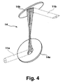
- Fig. 4 shows another beam-forming optical system 14 for converting the round laser pulse 11a into an elliptical laser pulse 11b.
- the beam-shaping optical system 14 is designed as a periscope telescope with two spherical concave mirrors 14a, 14b tilted towards the beam.
- the concave mirrors 14a, 14b have a sufficient focal length to avoid excessive aberrations and too small foci, in which due to high beam intensity could already occur in air non-linear effects, and may have the same radius of curvature.
- Plane deflecting mirrors between the periscope mirrors can reduce the overall height.
- the angle of incidence ⁇ at the periscope mirrors can be freely selected to achieve a certain magnification or reduction.
- a beam ellipticity of 1 / cos 4 ⁇ results.
- Larger ellipticities can be achieved with different angles of incidence, such as an aspect ratio of 16: 1 at an angle of incidence of 60 °. Larger axis ratios are practically meaningless.
- the use of telescopes in the resonator also has an advantageous effect due to the beam path extension effected by the telescope, which is the requirement for the switching speed and edge steepness of the optical switching element 9, 9 'correspondingly lowers.
- the beam-shaping optical system is arranged outside the amplifier resonator.
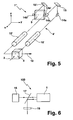
- Fig. 5 1 shows a further amplifier arrangement 1 "in an embodiment as a ring resonator with two rod-shaped amplifying elements 10.
- a laser pulse 2 to be amplified is coupled into the amplifier resonator 4 'via the polarization-dependent beam splitter 3.
- a ⁇ / 2 voltage is applied to the Pockels cell 9
- this voltage is switched off so that the pulse circulates in the resonator and is amplified, after which the ⁇ / 2 voltage is again applied to the Pockels cell so that the polarization is again rotated by 90 ° and the amplified pulse 12 leaves the amplifier resonator 4 'through the beam splitter 3.
- the first periscope telescope 14a, 14b forms an elliptical beam from the round beam before passing through the Pockels cell 9.
- the second periscope telescope 14b ', 14a' again forms a round beam from the elliptical beam.
- the deflecting mirrors 15, 15 ' are used to reduce the size of the amplifier arrangement 1 ".
- linear resonator are applied twice as high voltage to the Pockels cell, since the Pockels cell per revolution is traversed only once by the pulse.
- An advantage of the ring resonator design over the in Fig. 1 shown embodiment is that the beam path of the amplified laser pulses 12 is already spatially separated from that of the seed pulse 2.
- Fig. 6 schematically an ultrashort pulse laser 100 according to the invention is shown.
- the seed laser pulses generated by a seed laser 16 pass, if necessary via a separation unit 17, to an amplifier arrangement 1, 1 ', 1 "according to the invention
- the amplified laser pulses are emitted after leaving the amplifier arrangement by the separation unit 17, for example by a 45 ° Faraday rotator and a polarization-dependent beam splitter, separated from the seed laser pulses.
- an external switching element 18 is arranged for modulation of the amplified beam, which may also have a rectangular cross-section.
Abstract
Description
Die vorliegende Erfindung betrifft eine Anordnung zum Erzeugen und/oder Verstärken eines insbesondere gepulsten Laserstrahls mit annähernd rundem Strahlquerschnitt, umfassend einen Verstärkerresonator mit einem Verstärkungselement und einer Kopplungseinrichtung, die den verstärkten Laserstrahl abhängig vom Schaltzustand eines elektro-optischen oder akusto-optischen Schaltelements zumindest zum größten Teil aus dem Verstärkerresonator auskoppelt, wobei eine Strahlformungsoptik zum Umformen zwischen zwei unterschiedlichen Strahlquerschnitten des Laserstrahls vorgesehen ist, sowie einen Ultrakurzpulslaser mit einer solchen Verstärkeranordnung.The present invention relates to an arrangement for generating and / or amplifying a particular pulsed laser beam with approximately circular beam cross section comprising an amplifier resonator with a gain element and a coupling device, the amplified laser beam depending on the switching state of an electro-optical or acousto-optic switching element at least the largest Part decouples from the amplifier resonator, wherein a beam-forming optical system for forming between two different beam cross-sections of the laser beam is provided, and an ultrashort pulse laser with such an amplifier arrangement.
Eine derartige Verstärkeranordnung ist beispielsweise durch die
Die
Zur Erzeugung ultrakurzer Pulse mit hoher Pulsenergie (oberhalb von 1 µJ) werden in einem Seed-Laser ultrakurze Seed-Laserpulse mit geringer Pulsenergie erzeugt und anschließend in einem so genannten regenerativen Verstärker verstärkt, wie er beispielsweise in W. Koechner: "Solid-State Laser Engineering" (Springer Verlag, 1996) beschrieben ist. Gegebenenfalls kann der verstärkte Laserstrahl durch einen schnellen externen Modulator einzelpulsgenau leistungsmoduliert werden. Dabei stellt sich das Problem, dass bei der direkten Verstärkung der ultrakurzen Pulse Pulsspitzenleistungen erzeugt werden, die das Verstärkermedium und/oder optische Komponenten im und/oder nach dem Verstärker schädigen und/oder zu nichtlinearen Pulsverzerrungen führen. Typische Ultrakurzpulslaser-Verstärkersysteme mit Pulsdauern im Sub-Pikosekunden-Bereich basieren daher auf dem Verfahren der "Chirped-Pulse-Amplification" (CPA), bei dem die Laserpulsdauer vor der Verstärkung dispersiv verlängert und nach der Verstärkung mittels Prismen- oder in der Regel Gitterkompressoren wieder verkürzt wird. Nachteile solcher CPA-Verstärkersysteme sind ihre Komplexität und die schwierige hochgenaue Justage der dispersiven optischen Elemente sowie negative Auswirkungen auf die erreichbare Strahlqualität. Ferner ist die Effizienz des Kompressors üblicherweise gering. Der Kompressor erfordert zumeist eine lineare Polarisation des Laserlichtes, erhöht den Platzbedarf des Lasersystems und verursacht Kosten.To generate ultrashort pulses with high pulse energy (above 1 μJ) ultrashort seed laser pulses with low pulse energy are generated in a seed laser and subsequently amplified in a so-called regenerative amplifier, as described, for example, in W. Koechner: "Solid-State Laser Engineering "(Springer Verlag, 1996) is described. If necessary, the amplified laser beam can be power-modulated by a high-speed external modulator. This raises the problem that in the direct amplification of the ultrashort pulses pulse peak powers are generated which damage the amplifier medium and / or optical components in and / or after the amplifier and / or lead to nonlinear pulse distortions. Typical ultrafast laser amplifier systems with pulse durations in the sub-picosecond range are therefore based on the method of "Chirped Pulse Amplification" (CPA), in which the laser pulse duration extends dispersively before amplification and after amplification by means of prismatic or, as a rule, grating compressors is shortened again. Disadvantages of such CPA amplifier systems are their complexity and the difficult high-precision adjustment of the dispersive optical elements as well as negative effects on the achievable beam quality. Furthermore, the efficiency of the compressor is usually low. The compressor usually requires a linear polarization of the laser light, increases the space requirement of the laser system and causes costs.
Um die Komplexität von Ultrakurzpulslasern zu verringern, ist es aus
Ein regenerativer Verstärker in einem Ultrakurzpulslaser-System weist üblicherweise eine Ein/Aus-Kopplungseinrichtung auf, über die der Seed-Laserpuls in den Verstärker eingekoppelt und der verstärkte Laserpuls nach einer entsprechenden Zahl von Umläufen wieder ausgekoppelt wird. Die Kopplungseinrichtung besteht beispielsweise aus einem polarisationsabhängigen Strahlteiler, der den Laserpuls polarisationsabhängig transmittiert oder reflektiert, einem λ/4-Plättchen, das die Polarisation des im Verstärkerresonator umlaufenden Laserpulses im Doppeldurchgang um 90° dreht, und einem elektro-optischen Schalter in Form einer Pockelszelle, welche die Wirkung des λ/4-Plättchens beim Anlegen einer Schaltspannung gerade kompensiert. Der zu verstärkende Seed-Laserpuls tritt durch den Strahlteiler in den Verstärkerresonator ein. Anschließend durchläuft er das λ/4-Plättchen sowie die noch nicht unter Hochspannung stehende Pockelszelle, trifft auf den Resonator-Endspiegel und läuft durch Pockelszelle und λ/4-Plättchen zurück zum Strahlteiler. Durch den Doppeldurchgang durch das λ/4-Plättchen ist die Polarisation um 90° gedreht, so dass der Laserpuls vom Strahlteiler zum Verstärkungsmedium reflektiert wird. Nun wird die Hochspannung so an die Pockelszelle angelegt, dass für alle folgenden Umläufe die Wirkung des λ/4-Plättchens kompensiert wird. Der Laserpuls mit gedrehter Polarisation läuft also so lange im Verstärkerresonator um, wie Hochspannung an der Pockelszelle anliegt. Beim Abschalten der Hochspannung tritt eine erneute Drehung der Polarisation des Laserpulses durch das λ/4-Plättchen ein, so dass der verstärkte Laserpuls anschließend über den Strahlteiler aus dem Verstärker ausgekoppelt wird. Das λ/4-Plättchen kann entfallen, wenn während der Ein- und Auskopplung Hochspannung an der Pockelszelle angelegt wird und während der Verstärkung nicht. Derartige Verstärker sind bekannt und existieren in zahlreichen Varianten, so z. B. auch als Ringverstärker, bei dem die Endspiegel entfallen und die Pockelszelle und das Verzögerungsplättchen (λ/2-Plättchen) pro Umlauf nur einmal vom Laserpuls durchlaufen werden. Dabei bestimmt die Zeitdauer für einen einzelnen Umlauf des Laserpulses im Verstärkerresonator die Zeitanforderung an die Schaltflanke der Schalteinheit für die Hochspannung an der Pockelszelle.A regenerative amplifier in an ultrashort pulse laser system usually has an on / off coupling device, via which the seed laser pulse is coupled into the amplifier and the amplified laser pulse is coupled out again after a corresponding number of cycles. The coupling device consists for example of a polarization-dependent beam splitter, which transmits or reflects the laser pulse polarization-dependent, a λ / 4 plate, which rotates the polarization of the circulating in the amplifier resonator laser pulse in the double pass through 90 °, and an electro-optical switch in the form of a Pockels cell, which just compensates for the effect of the λ / 4 plate when applying a switching voltage. The seed laser pulse to be amplified enters the amplifier resonator through the beam splitter. He then passes through the λ / 4 plate and the not yet under high voltage Pockels cell, strikes the resonator end mirror and passes through Pockels cell and λ / 4 plate back to the beam splitter. Due to the double passage through the λ / 4 plate, the polarization is rotated by 90 °, so that the laser pulse is reflected by the beam splitter to the gain medium. Now the high voltage is applied to the Pockels cell so that the effect of the λ / 4 plate is compensated for all subsequent rounds. The laser pulse with rotated polarization thus runs in the amplifier resonator as long as high voltage is applied to the Pockels cell. When switching off the high voltage, a renewed rotation of the polarization of the laser pulse through the λ / 4 plate occurs, so that the amplified laser pulse is then coupled out via the beam splitter from the amplifier. The λ / 4 plate can be omitted if during the coupling and decoupling high voltage is applied to the Pockels cell and not during the amplification. Such amplifiers are known and exist in numerous variants, such. B. also as a ring amplifier, in which account the end mirror and the Pockels cell and the retardation plate (λ / 2 plate) per revolution are traversed only once by the laser pulse. The time duration for a single revolution of the laser pulse in the amplifier resonator determines the time requirement for the switching edge of the switching unit for the high voltage at the Pockels cell.
Bei einer ausreichend langen Umlaufdauer des Laserpulses im Verstärker kann anstelle der oben beschriebenen elektro-optischen Ein/Aus-Kopplungseinrichtung mit einer Pockelszelle auch ein akusto-optischer Schalter verwendet werden, mit dem ebenfalls die Richtung des transmittierten Strahles geändert werden kann. Dazu wird durch einen Hochfrequenzgenerator eine akustische Schallwelle im akusto-optischen Schalter erzeugt, an welcher der Laserstrahl gebeugt wird. Die Schaltgeschwindigkeit des akusto-optischen Schalters ist unter anderem durch die Ausbreitungszeit der Schallwelle quer über den Strahldurchmesser beschränkt, also durch Schallgeschwindigkeit und Strahldurchmesser. Da das Schallfeld zum Ein- oder Auskoppeln für die Dauer des Laserpulses über den gesamten Strahlquerschnitt anliegen muss, wirkt sich die Ausdehnung des Strahls in Schallausbreitungsrichtung auch auf die erforderliche Energie des Hochfrequenzpulses aus, der zum Schalten erforderlich ist. Ausreichend lange Umlaufzeiten des Laserpulses im Verstärker können beispielsweise mit Multipass-Anordnungen erreicht werden, bei denen die im Verstärker umlaufende Strahlung mehrfach über das Verstärkungselement geführt wird.With a sufficiently long circulation time of the laser pulse in the amplifier, instead of the above-described electro-optical on / off coupling device with a Pockels cell, an acousto-optical switch can also be used with which also the direction of the transmitted beam can be changed. For this purpose, an acoustic sound wave in the acousto-optical switch is generated by a high-frequency generator, at which the laser beam is diffracted. The switching speed of the acousto-optic switch is limited, inter alia, by the propagation time of the sound wave across the beam diameter, ie by the speed of sound and beam diameter. Since the sound field must be present for coupling or decoupling for the duration of the laser pulse over the entire beam cross section, the expansion of the beam in the direction of sound propagation also affects the required energy of the high-frequency pulse, which is required for switching. Sufficiently long circulation times of the laser pulse in the amplifier can be achieved, for example, with multipass arrangements, in which the radiation circulating in the amplifier is conducted repeatedly over the reinforcement element.
Bei Verwendung eines regenerativen Verstärkers zur direkten Verstärkung ultrakurzer Laserpulse ohne CPA weisen die Laserpulse im Verstärker und insbesondere auch in der Kopplungseinrichtung einen verhältnismäßig großen Durchmesser auf, um Beschädigungen an den optischen Elementen zu vermeiden und den Einfluss nichtlinearer Effekte zu begrenzen. Einen solchen Laserstrahl mit großem Strahldurchmesser optisch zu schalten, erfordert eine Schaltanordnung mit entsprechend großer Apertur. Dies erhöht in der bisher üblichen und kommerziell erhältlichen Ausführung des elektro-optischen oder akusto-optischen Schalters die Schaltzeiten und/oder verringert die mögliche Taktrate. Bei transversal wirkenden Pockelszellen ist die elektrische Schaltspannung proportional zum Abstand der Elektroden und damit zur Dicke des Pockelszellen-Kristalls. Die Verlustleistung der Treiberelektronik wächst quadratisch mit dem Abstand der Elektroden.When using a regenerative amplifier for directly amplifying ultrashort laser pulses without CPA, the laser pulses in the amplifier and in particular in the coupling device have a relatively large diameter in order to avoid damage to the optical elements and to limit the influence of non-linear effects. To optically switch such a laser beam with a large beam diameter requires a switching arrangement with a correspondingly large aperture. This increases in the hitherto customary and commercially available design of the electro-optical or acousto-optical switch, the switching times and / or reduces the possible clock rate. In transversely acting Pockels cells, the electrical switching voltage is proportional to the distance between the electrodes and thus to the thickness of the Pockels cell crystal. The power loss of the driver electronics grows quadratically with the distance of the electrodes.
Die Schaltspannung an der Pockelszelle kann dadurch verringert werden, dass die Pockelszelle pro Resonatorumlauf mehr als zweimal vom Strahl durchlaufen wird, so dass sich die notwendige Verzögerung auf mehrere Durchgänge durch die Pockelszelle verteilt. Es können beispielsweise Doppelzellen verwendet werden, die aus zwei Einzelzellen bestehen, welche synchron angesteuert und pro Resonatorumlauf doppelt (hin und zurück) durchlaufen werden. Die Doppelzelle kann auch aus einem einzelnen Kristall aufgebaut sein, der nebeneinander zweimal (je hin- und zurück) durchlaufen wird. In solchen Anordnungen, in denen die Verringerung der Schaltspannung durch die Verlängerung des Strahlweges durch das Pockelszellenmaterial erreicht wird, muss zur Einhaltung der maximal erlaubten nichtlinearen Pulsverzerrung die Pulsenergie proportional zur Verringerung der Schaltspannung reduziert werden. Ein weiterer Nachteil von Doppelzellen ist die höhere Anzahl der Grenzflächen, die der Strahl durchlaufen muss und an denen Verluste, z.B. durch unerwünschte Reflexion, auftreten können.The switching voltage at the Pockels cell can be reduced by traversing the Pockels cell more than twice from the beam per cavity revolution, so that the necessary delay is distributed over several passes through the Pockels cell. For example, double cells can be used, which consist of two individual cells, which are controlled synchronously and run through twice (back and forth) per resonator cycle. The double cell can also be made up of a single crystal which is juxtaposed twice (ever go back and forth). In such arrangements, where the reduction in switching voltage is achieved by extending the beam path through the Pockels cell material, to maintain the maximum allowable nonlinear pulse distortion, the pulse energy must be reduced in proportion to the reduction in switching voltage. Another disadvantage of double cells is the higher number of interfaces that the beam has to pass through and where losses, eg due to unwanted reflection, can occur.
Demgegenüber ist es die Aufgabe der vorliegenden Erfindung, eine Verstärkeranordnung der eingangs genannten Art dahingehend weiterzubilden, dass die zum Schalten des optischen Schaltelements erforderliche elektrische Energie sowie die Schaltzeiten verringert werden können und dass dabei Laserpulse mit gleicher oder höherer Pulsenergie geschaltet werden können.In contrast, it is the object of the present invention to develop an amplifier arrangement of the type mentioned in that the required for switching the optical switching element electrical energy and the switching times can be reduced and that thereby laser pulses with the same or higher pulse energy can be switched.
Diese Aufgabe wird erfindungsgemäß dadurch gelöst, dass der Laserstrahl beim Eintritt in das elektro-optische oder akusto-optische Schaltelement einen elliptischen Strahlquerschnitt aufweist, dass der Querschnitt des elektro-optischen oder akusto-optischen Schaltelements rechtwinklig zur Strahlrichtung annähernd rechteckförmig ist, dass die Strahlformungsoptik den runden Strahlquerschnitt des Laserstrahls auf einen an den rechteckförmigen Querschnitt des elektro-optischen oder akusto-optischen Schaltelements angepassten, elliptischen Strahlquerschnitt umformt, dass die elliptische Strahlquerschnittfläche größer als die kleinste runde Strahlquerschnittfläche im Strahlengang des Verstärkerresonators ist, und/oder dass der rechtwinklig zur Strahlrichtung annähernd rechteckförmige Querschnitt des elektrooptischen oder akusto-optischen Schaltelements durch eine kürzere und eine längere Seite definiert ist, wobei die Länge der kürzeren Seite kleiner und die Länge der längeren Seite größer als der größte Strahldurchmesser des runden Laserstrahls im Verstärkerresonator ist.This object is achieved in that the laser beam when entering the electro-optical or acousto-optic switching element has an elliptical beam cross-section, that the cross-section of the electro-optical or acousto-optical switching element is rectangular at right angles to the beam direction approximately rectangular that the beam shaping optics round beam cross-section of the laser beam to an adapted to the rectangular cross-section of the electro-optical or acousto-optical switching element, elliptical beam cross section transforms that the elliptical beam cross-sectional area is larger than the smallest round beam cross-sectional area in the beam path of the amplifier resonator, and / or that approximately perpendicular to the beam direction Rectangular cross section of the electro-optical or acousto-optic switching element is defined by a shorter and a longer side, wherein the length of the shorter side is smaller and the length of the length ren side larger than the largest beam diameter of the round laser beam in the amplifier resonator is.
Unter annähernd rechteckförmig ist zu verstehen, dass der Querschnitt des optischen Schaltelements die Form eines Rechtecks, Trapezes oder Parallelogramms aufweisen kann. Geringfügige Abweichungen von der Grundform, z.B. Fasen oder Rundungen an den Kanten, entsprechen ebenfalls der erfindungsgemäßen Gestalt des Schaltelements. Allgemein sind erfindungsgemäß die Querschnittfläche der aktiven Apertur des Schaltelements und der elliptische Strahlquerschnitt aneinander angepasst. Mit aktiver Apertur des Schaltelements wird die Querschnittfläche bezeichnet, die optisch zu Schaltung nutztbar ist.Under approximately rectangular is to be understood that the cross section of the optical switching element may have the shape of a rectangle, trapezoid or parallelogram. Minor deviations from the basic shape, such as chamfers or curves on the edges, also correspond to the shape of the switching element according to the invention. General are according to the invention the cross-sectional area of the active aperture of the switching element and the elliptical beam cross-section adapted to each other. With active aperture of the switching element, the cross-sectional area is referred to, which is optically usable circuit.
Die Geometrie des Schaltelements kann weiter optimiert werden, z.B. zur Vermeidung akustischer Resonanzeffekte. So führen in der Regel rationale Verhältnisse der Kantenlängen eines Quaders aus einem isotropen Material zur Entartung akustischer Resonanzen, welche vermieden werden sollte. Dazu ist es beispielsweise vorteilhaft, das Achsenverhältnis des optischen Schaltelements nicht im Verhältnis 3:2, sondern im Verhältnis des goldenen Schnitts zu wählen. Für größere Achsverhältnisse gelten solche Überlegungen entsprechend. Für kompliziertere und nicht isotrope Materialien können Schwingungsresonanzen berechnet und/oder vermessen und die Form des Schaltelementes optimiert werden, um unerwünschte Resonanzeffekte zu unterdrücken.The geometry of the switching element can be further optimized, e.g. to avoid acoustic resonance effects. As a rule, rational relationships of the edge lengths of a cuboid made of an isotropic material lead to the degeneration of acoustic resonances, which should be avoided. For this purpose, it is advantageous, for example, not to choose the axial ratio of the optical switching element in the ratio 3: 2, but in the ratio of the golden section. For larger axle ratios such considerations apply accordingly. For more complicated and non-isotropic materials, vibration resonances can be calculated and / or measured, and the shape of the switching element optimized to suppress unwanted resonance effects.
Erfindungsgemäß weist das Strahlprofil der Laserpulse im Verstärkerresonator zumindest über eine bestimmte Weglänge einen näherungsweise elliptischen Querschnitt auf, und diese elliptischen Pulse werden durch ein optisches Schaltelement geschaltet, dessen rechteckförmiger Querschnitt an das elliptische Strahlprofil angepasst ist oder umgekehrt. Gegenüber den bisher üblichen Geometrien von optischen Schaltern für runde Strahlprofile, die rechtwinklig zur Strahlrichtung einen quadratischen Querschnitt aufweisen, bietet dies bei elektrooptischen Schaltern den Vorteil einer besseren Kühlung des Modulators, einer geringeren Verlustleistung in der Treiberelektronik sowie einer höheren Schaltgeschwindigkeit bzw. Taktrate bei gleicher Pulsenergie. Bei akusto-optischen Schaltern werden geringere Schaltzeiten sowie eine Minderung der erforderlichen mittleren Treiberleistung erreicht. Dabei bietet der elliptische Strahlquerschnitt eine höhere Flexibilität bei der Wahl der Querschnittfläche des optischen Schaltelements, um eine ausreichend geringe Pulsintensität zur Vermeidung von Beschädigungen und/oder übermäßigen nichtlinearen Pulsverzerrungen zu erreichen.According to the invention, the beam profile of the laser pulses in the amplifier resonator has an approximately elliptical cross section over a certain path length, and these elliptical pulses are switched by an optical switching element whose rectangular cross section is adapted to the elliptical beam profile or vice versa. Compared with the usual geometries of optical switches for round beam profiles, which have a square cross-section perpendicular to the beam direction, this offers the advantage of better cooling of the modulator, a lower power loss in the driver electronics and a higher switching speed or clock rate at the same pulse energy at electro-optical switches , With acousto-optic switches, shorter switching times and a reduction in the required average driver power are achieved. In this case, the elliptical beam cross-section offers greater flexibility in the choice of the cross-sectional area of the optical switching element, in order to achieve a sufficiently low pulse intensity to avoid damage and / or excessive non-linear pulse distortion.
Der Strahldurchmesser in Richtung der kürzeren Ellipsenachse kann geringer als der Durchmesser des runden Strahls gewählt werden, so dass auch die Länge der kürzeren Seite des rechteckförmigen optischen Schaltelements kleiner sein kann als der runde Strahldurchmesser. Hierbei wird die Länge der längeren Seite größer als der Strahldurchmesser des runden Laserstrahls gewählt und der elliptische Laserstrahl kann die gleiche Maximalintensität (Flächenleistungsdichte) wie der runde Eingangslaserstrahl aufweisen. In diesem Fall können die Schaltzeiten verringert werden. Pro Schaltvorgang tritt außerdem bei elektrooptischen Schaltelementen eine geringere elektrische Verlustleistung auf. So benötigt ein elliptischer Strahl mit einem Achsenverhältnis 4:1, der verglichen mit dem runden Strahl in seiner einen Achse auf die Hälfte gestaucht und in seiner anderen Achse auf das Doppelte gestreckt wird, eine nur halb so hohe (wenn auch doppelt so breite) Pockelszelle und somit nur die halbe Schaltspannung, was thermisch einer ca. 4-fachen Taktrate bei gleicher Kühlung entspricht. Größere Elliptizitäten, z.B. mit einem Achsenverhältnis 16:1, ermöglichen eine noch weitere Reduzierung der Schaltspannung und Erhöhung der Taktrate.The beam diameter in the direction of the shorter ellipse axis can be chosen smaller than the diameter of the round beam, so that the length of the shorter side of the rectangular optical switching element can be smaller than the round beam diameter. Here, the length of the longer side is made larger than the beam diameter of the round laser beam and the elliptical laser beam can have the same maximum intensity (area power density) as the round input laser beam. In this case, the switching times can be reduced. Each switching operation also occurs in electro-optical switching elements to a lower electrical power loss. For example, an elliptical beam with a 4: 1 aspect ratio, compressed to one half of its one axis and doubled in its other axis, requires only half as much (although twice as wide) a Pockels cell and thus only half the switching voltage, which thermally corresponds to an approximately 4 times the clock rate with the same cooling. Larger ellipticities, eg with a 16: 1 aspect ratio, allow even further reduction of the switching voltage and increase of the clock rate.
Ist die Strahlquerschnittfläche des geformten Laserstrahls größer als die runde Strahlquerschnittfläche des Eingangslaserstrahls, so ermöglicht dies die Erzeugung und Schaltung von Laserpulsen mit höherer Pulsenergie bei gleichbleibender Schaltgeschwindigkeit. So können bei Vervierfachung der Strahlquerschnittfläche beispielsweise Pulse mit vervierfachter Pulsenergie geschaltet werden. Auch eine Absenkung der Schaltspannung ist möglich, da beispielsweise bei gleicher Pulsenergie und gesteigerter Strahlquerschnittfläche vergleichbare Pulsverzerrungen durch Nichtlinearitäten erst bei größerer Länge des Schaltelements auftreten.If the beam cross-sectional area of the shaped laser beam is larger than the circular beam cross-sectional area of the input laser beam, this allows the generation and switching of laser pulses with higher pulse energy at a constant switching speed. For example, when the beam cross-sectional area is quadrupled, pulses with quadrupled pulse energy can be switched. A lowering of the switching voltage is also possible because, for example, with the same pulse energy and increased beam cross-sectional area, comparable pulse distortions due to nonlinearities only occur with a larger length of the switching element.
Die Vergrößung der Querschnittfläche des elliptischen Laserstrahls gegenüber dem runden Laserstrahl erfolgt entweder bereits in der Strahlformungsoptik oder durch eine zusätzliche Opik, wie z.B. ein zweites Teleskop im Resonator, das den Querschnitt der Laserpulse ohne weitere Änderung des Achsenverhältnisses vergrößert.The enlargement of the cross-sectional area of the elliptical laser beam with respect to the round laser beam takes place either already in the beam-shaping optical system or by an additional opaqueness, such as e.g. a second telescope in the resonator, which increases the cross section of the laser pulses without further change of the axial ratio.
Die erfindungsgemäße Anordnung lässt sich analog auch zur Erzeugung eines gepulsten Laserstrahls mittels Auskoppelmodulation (gebräuchlichere Bezeichnung: engl. "cavity dumping") nutzen. Hierbei wird kein Seed-Laserpuls in den Resonator eingekoppelt, sondern die Laserpulse werden direkt im Resonator erzeugt. Das optische Schaltelement dient dazu, die im Resonator umlaufende Strahlung auf einmal aus dem Resonator auszukoppeln, wie es beispielsweise in W. Koechner: "Solid-State Laser Engineering" (Springer Verlag, 1996) beschrieben ist. Ist im Resonator außerdem ein optisches Element zur Modenkopplung vorhanden, so werden direkt ultrakurze Laserpulse erzeugt. Wird mit Hilfe des optischen Schaltelements nicht die gesamte Strahlung ausgekoppelt, sondern ein geringer Teil im Resonator belassen, so wirkt dieser Anteil der Strahlung analog zu einem Seed-Laserpuls in einer Verstärkeranordnung. Auch beim auskoppelmodulierten Oszillatorbetrieb mit Modenkopplung ist es das Ziel, ultrakurze Laserpulse mit möglichst hoher Pulsenergie zu erzeugen und diese möglichst schnell zu schalten, was durch die Verwendung eines rechteckförmigen optischen Schaltelements und einen darauf angepassten elliptischen Strahlquerschnitt im Resonator vereinfacht wird.The arrangement according to the invention can also be used analogously for generating a pulsed laser beam by means of coupling-out modulation (more commonly referred to as "cavity dumping"). In this case, no seed laser pulse is coupled into the resonator, but the laser pulses are generated directly in the resonator. The optical switching element serves to the circulating in the resonator radiation Once out of the resonator, as described for example in W. Koechner: "Solid-State Laser Engineering" (Springer Verlag, 1996). If an optical element for mode locking is also present in the resonator, ultrashort laser pulses are generated directly. If not all of the radiation is coupled out with the aid of the optical switching element, but a small part is left in the resonator, then this fraction of the radiation acts analogously to a seed laser pulse in an amplifier arrangement. Even when decoupled modulated oscillator mode with mode coupling, the goal is to produce ultra-short laser pulses with the highest possible pulse energy and turn them as quickly as possible, which is simplified by the use of a rectangular optical switching element and an adapted elliptical beam cross section in the resonator.
In einer erfindungsgemäßen auskoppelmodulierten Oszillatoranordnung ist die Strahlformungsoptik innerhalb des Resonators angeordnet. Bei einer Verstärkeranordnung kann die Strahlformungsoptik innerhalb oder außerhalb des Verstärkerresonators angeordnet sein. Im ersteren Fall ist die Strahlformungsoptik im Verstärkerresonator vorzugsweise zwischen der Kopplungseinrichtung und einem Endspiegel angeordnet, so dass der Laserstrahl nach dem Doppeldurchgang durch die Strahlformungsoptik wieder mit rundem Strahlquerschnitt auskoppelbar ist. Im letzteren Fall ist vorteilhafterweise im Verstärkerresonator eine weitere Strahlformungsoptik angeordnet, die den elliptischen Strahlquerschnitt der eingekoppelten Laserpulse wieder in einen runden Strahlquerschnitt umformt, wenn das Verstärkungselement einen runden Querschnitt aufweist.In a decoupled-modulated oscillator arrangement according to the invention, the beam-shaping optical system is arranged inside the resonator. In an amplifier arrangement, the beam shaping optics can be arranged inside or outside the amplifier resonator. In the former case, the beam-shaping optical system in the amplifier resonator is preferably arranged between the coupling device and an end mirror, so that the laser beam can be decoupled again with a round beam cross-section after the double pass through the beam-shaping optical system. In the latter case, a further beam shaping optics is advantageously arranged in the amplifier resonator, which converts the elliptical beam cross section of the coupled laser pulses back into a round beam cross section, when the reinforcing element has a round cross section.
In einer Ausführungsform der Erfindung umfasst die Strahlformungsoptik zur Erzeugung eines elliptischen Strahlquerschnitts mindestens ein anamorphotisches Prismenpaar. Dadurch wird die Strahlquerschnittfläche des annähernd runden Eingangsstrahls in einer Raumrichtung vergrößert oder verkleinert.In one embodiment of the invention, the beam-shaping optical system for generating an elliptical beam cross-section comprises at least one anamorphic prism pair. As a result, the beam cross-sectional area of the approximately round input beam is enlarged or reduced in one spatial direction.
In einer bevorzugten Ausführungsform der Erfindung ist die Strahlformungsoptik als Teleskop insbesondere mit anamorphotischen Linsen ausgebildet. Dazu werden beispielsweise eine zylindrische Plankonvexlinse und eine zylindrische Plankonkavlinse mit ihren Planseiten und um 90° gegeneinander gedrehter Symmetrieachse zusammengefügt. Das Teleskop wird aus zwei solchen Linsenpaaren mit gegeneinander um 90° gedrehter Symmetrieachse gebildet. Das Teleskop formt beispielsweise durch Verdreifachung des Pulsdurchmessers in der einen Richtung und Drittelung des Pulsdurchmessers in der dazu rechtwinkligen Richtung elliptische Pulse mit einem Achsenverhältnis von 9:1, welche die gleiche Intensität wie die runden Eingangspulse aufweisen. Die Auslegung des Teleskops wird so gewählt, dass mögliche Zwischenfoki ausreichend groß sind und an geeigneter Position auftreten, um nichtlineare Effekte, Luftdurchbrüche, sowie Schädigung optischer Komponenten zu vermeiden. Die Ausführung der Strahlformungsoptik als Teleskop ist vorteilhaft, da der Strahlengang nur in dem Resonatorarm beeinflusst wird, in dem das optische Schaltelement angeordnet ist.In a preferred embodiment of the invention, the beam-shaping optical system is designed as a telescope, in particular with anamorphic lenses. For this example, a cylindrical plano-convex lens and a cylindrical Plankonkavlinse with their planets and rotated by 90 ° to each other Symmetry axis joined together. The telescope is made up of two such pairs of lenses with an axis of symmetry rotated by 90 ° with respect to each other. For example, by tripling the pulse diameter in one direction and one third of the pulse diameter in the direction orthogonal thereto, the telescope forms elliptical pulses having an aspect ratio of 9: 1 and having the same intensity as the round input pulses. The design of the telescope is chosen so that possible Zwischenfoki are sufficiently large and occur in a suitable position to avoid non-linear effects, air leaks, and damage to optical components. The embodiment of the beam-shaping optical system as a telescope is advantageous because the beam path is only influenced in the resonator arm in which the optical switching element is arranged.
In einer anderen bevorzugten Ausführungsform weist die Strahlformungsoptik zwei zum einfallenden Laserstrahl verkippte gekrümmte Spiegel auf. Von Vorteil sind dabei sphärische Konkavspiegel mit im Vergleich zum Strahldurchmesser ausreichend großer Brennweite, um übermäßige Abbildungsfehler zu vermeiden. Beide Spiegel können denselben Krümmungsradius aufweisen. Der Einfallswinkel kann zum Erreichen einer bestimmten Vergrößerung/Verkleinerung frei gewählt werden.In another preferred embodiment, the beam shaping optics has two curved mirrors tilted to the incident laser beam. Advantageous in this case are spherical concave mirrors with a focal length which is sufficiently large in comparison to the beam diameter in order to avoid excessive aberrations. Both mirrors can have the same radius of curvature. The angle of incidence can be chosen freely to achieve a certain magnification / reduction.
Alternativ können statt der Spiegel auch zum Laserstrahl verkippte Linsen zum Einsatz kommen. Alternativ können auch Toroidspiegel zur Strahlformung eingesetzt werden. Alternativ können die anamorphotischen Linsen auch als Gradientenlinsen ausgeführt sein.Alternatively, instead of the mirror, lenses tilted to the laser beam can also be used. Alternatively, toroidal mirrors can be used for beam shaping. Alternatively, the anamorphic lenses may also be designed as gradient lenses.
Eine weitere vorteilhafte Ausführungsform der Erfindung sieht vor, dass die Kopplungseinrichtung einen polarisationsabhängigen Strahlteiler und das optische Schaltelement eine Pockelszelle aufweist. Für die Pockelszelle kommen sämtliche bekannten Pockelszellenmaterialien in Frage, z.B. BBO, KD*P, RTP und andere, sowie gebondete Materialien. Das optische Schaltelement kann zur weiteren Reduzierung der Schaltspannung und/oder zur Kompensation von thermischer Doppelbrechung aus mehreren Zellen ausgeführt sein, beispielsweise in Form einer Doppelzelle aus zwei Kristallen, die unter Hochspannung jeweils nur eine Verzögerung um ein Achtel der Wellenlänge bewirken.A further advantageous embodiment of the invention provides that the coupling device has a polarization-dependent beam splitter and the optical switching element has a Pockels cell. For the Pockels cell, all known Pockels cell materials are suitable, eg BBO, KD * P, RTP and others, as well as bonded materials. The optical switching element can be designed to further reduce the switching voltage and / or to compensate for thermal birefringence of a plurality of cells, for example in the form of a double cell of two crystals, which cause only a delay of one-eighth of the wavelength under high voltage.
In einer anderen vorteilhaften Ausführungsform der Erfindung sind sowohl die Kopplungseinrichtung als auch das optische Schaltelement durch einen akusto-optischen Schalter gebildet. Bei einem rechteckförmigen akusto-optischen Schalter wird im Vergleich zu einem Schalter mit quadratischem Querschnitt eine geringere HF-Treiberleistung benötigt, wenn die Piezo-Transducer an den kurzen Seiten des Schalters angebracht sind. Werden die Piezo-Transducer dagegen an den langen Seiten des Schalters angebracht, so verringert sich die Schaltzeit.In another advantageous embodiment of the invention, both the coupling device and the optical switching element are formed by an acousto-optical switch. A rectangular acousto-optic switch requires less RF drive power as compared to a square cross-section switch when the piezo transducers are mounted on the short sides of the switch. If the piezo transducers on the other hand to the long Side of the switch attached, so the switching time is reduced.
Die vorliegende Erfindung betrifft auch einen Ultrakurzpulslaser mit einem Seed-Laser zur Erzeugung von Seed-Laserpulsen und mit einer wie oben beschriebenen Anordnung zum Verstärken der Seed-Laserpulse. Dieser erfindungsgemäße Ultrakurzpulslaser ermöglicht ein schnelles Schalten von ultrakurzen Laserpulsen mit möglichst geringer Schaltspannung sowie eine hohe Verstärkung der Seed-Laserpulse.The present invention also relates to an ultrashort pulse laser with a seed laser for generating seed laser pulses and with an arrangement for amplifying the seed laser pulses as described above. This ultrashort pulsed laser according to the invention enables a fast switching of ultrashort laser pulses with the lowest possible switching voltage as well as a high gain of the seed laser pulses.
Die vorliegende Erfindung betrifft auch einen Ultrakurzpulslaser mit einer wie oben beschriebenen Anordnung zur Erzeugung und Verstärkung von Laserpulsen und einem optischen Element zur Modenkopplung, das innerhalb des Laserresonators angeordet ist. Dieser erfindungsgemäße Ultrakurzpulslaser ermöglicht die Erzeugung von Laserpulsen mit hoher Pulsenergie und schnelle Auskopplung dieser Pulse.The present invention also relates to an ultrashort pulse laser having an arrangement as described above for generating and amplifying laser pulses and a mode-locking optical element disposed within the laser cavity. This ultrashort pulse laser according to the invention enables the generation of laser pulses with high pulse energy and rapid decoupling of these pulses.
Weitere Vorteile der Erfindung ergeben sich aus der Beschreibung und den Zeichnungen. Ebenso können die vorstehend genannten und die noch weiter aufgeführten Merkmale je für sich oder zu mehreren in beliebigen Kombinationen Verwendung finden. Die gezeigten und beschriebenen Ausführungsformen sind nicht als abschließende Aufzählung zu verstehen, sondern haben vielmehr beispielhaften Charakter für die Schilderung der Erfindung.Further advantages of the invention will become apparent from the description and the drawings. Likewise, the features mentioned above and the features listed further can be used individually or in combination in any combination. The embodiments shown and described are not to be understood as exhaustive enumeration, but rather have exemplary character for the description of the invention.
Es zeigen:
- Fig. 1
- ein erstes Ausführungsbeispiel der erfindungsgemäßen Verstärkeranordnung mit einem elektro-optischen Schalter (Pockelszelle) in einer Seitenansicht (
Fig. 1a ) und in einer Draufsicht (Fig. 1 b) ; - Fig. 2
- die Ansicht der in
Fig. 1 gezeigten Pockelszelle in Strahlrichtung; - Fig. 3
- ein zweites Ausführungsbeispiel der erfindungsgemäßen Verstärkeranordnung mit einem akusto-optischen Schalter in einer Seitenansicht (
Fig. 3a ) und in einer Draufsicht (Fig. 3b ); - Fig. 4
- eine als Periskop-Teleskop ausgebildete Strahlformungsoptik;
- Fig. 5
- ein drittes Beispiel einer erfindungsgemäßen Verstärkeranordnung in einer Ausführung als Ringresonator mit einem elektro-optischen Schalter (Pockelszelle); und
- Fig. 6
- eine schematische Darstellung eines erfindungsgemäßen Ultrakurzpulslasers.
- Fig. 1
- A first embodiment of the amplifier arrangement according to the invention with an electro-optical switch (Pockels cell) in a side view (
Fig. 1a ) and in a plan view (Fig. 1 b) ; - Fig. 2
- the view of in
Fig. 1 shown Pockels cell in the beam direction; - Fig. 3
- A second embodiment of the amplifier arrangement according to the invention with an acousto-optical switch in a side view (
Fig. 3a ) and in a plan view (Fig. 3b ); - Fig. 4
- a beam-forming optical system designed as a periscope telescope;
- Fig. 5
- A third example of an amplifier arrangement according to the invention in an embodiment as a ring resonator with an electro-optical switch (Pockels cell); and
- Fig. 6
- a schematic representation of an ultrashort pulse laser according to the invention.
Die in
Der zu verstärkende Eingangslaserstrahl 2 wird über einen polarisationsabhängigen Strahlteiler 3 in einen Verstärkerresonator 4 eingekoppelt, welcher endseitig jeweils einen hochreflektierenden Rückspiegel 5, 6 aufweist. Das runde Strahlprofil des eingekoppelten Laserpulses wird dann in einer Strahlformungsoptik 7 in einen elliptischen Querschnitt umgeformt. Der elliptische Laserpuls durchläuft anschließend ein λ/4-Plättchen 8 sowie eine noch nicht unter Hochspannung stehende Pockelszelle 9, trifft auf den Rückspiegel 5 und läuft durch Pockelszelle 9, λ/4-Plättchen 8 und Strahlformungsoptik 7, welche den Laserpuls wieder in einen runden Querschnitt umformt, zurück zum Strahlteiler 3. Durch den Doppeldurchgang durch das λ/4-Plättchen 8 ist die Polarisation des Laserpulses um 90° gedreht, so dass der Laserpuls vom Strahlteiler 3 zum Verstärkungselement (z.B. Scheibenlaserkristall) 10 durchgelassen wird. Nach Durchlauf durch das Verstärkerelement 10 wird der Laserpuls am Rückspiegel 6, der durch die verspiegelte Rückseite des Verstärkungselements 10 gebildet sein kann, reflektiert und durchläuft erneut das Verstärkerelement 10. Zwischenzeitlich ist an die Pockelszelle 9 solch eine Hochspannung angelegt, dass für alle folgenden Umläufe des Laserpulses im Verstärkerresonator 4 die vom λ/4-Plättchen 8 bewirkte Polarisationsdrehung von der Pockelszelle 9 kompensiert wird. Der im Verstärkerresonator 4 umlaufende Laserpuls hat zwischen linkem Rückspiegel 6 und Strahlformungsoptik 7 einen runden Strahlquerschnitt (runder Laserpuls 11a) und zwischen Strahlformungsoptik 7 und rechtem Rückspiegel 5 einen elliptischen Strahlquerschnitt (elliptischer Laserpuls 11b). Der Laserpuls mit um 90° gedrehter Polarisation läuft so lange im Verstärkerresonator 4 um, wie die Hochspannung an der Pockelszelle 9 anliegt.The
Nach Abschalten der Hochspannung tritt eine erneute 90°-Drehung der Polarisation des Laserpulses durch das λ/4-Plättchen 8 ein, so dass der Laserpuls nun über den polarisationsabhängigen Strahlteiler 3 als verstärkter Laserpuls 12 mit rundem Strahlquerschnitt aus dem Verstärkerresonator 4 ausgekoppelt wird.After switching off the high voltage, a renewed 90 ° rotation of the polarization of the laser pulse through the λ / 4
Das λ/4-Plättchen 8 kann entfallen, wenn während der Ein- und Auskopplung Hochspannung an die Pockelszelle 9 angelegt wird und während der Verstärkung nicht. Wie in
In einer auskoppelmodulierten Oszillatorausführung der Anordnung 1 wird kein Eingangslaserstrahl in die Anordnung 1 eingekoppelt. Die durch spontane Emission gestartete Laserstrahlung läuft so lange im Resonator um, wie an der Pockelszelle 9 Spannung anliegt. Durch die im Resonator befindliche Strahlformungsoptik 7 wird der Strahlquerschnitt der umlaufenden Laserstrahlung an die Geometrie des Verstärkungselements 10 und der Pockelszelle 9 angepasst. Beim Abschalten der Hochspannung an der Pockelszelle wird die Polarisation der Laserstrahlung um 90° gedreht, so dass der Ausgangslaserstrahl 12 ausgekoppelt wird. Verbleibt dabei ein geringer Anteil der Laserstrahlung im Resonator, so wirkt dieser Anteil nach erneutem Anlegen der Hochspannung an der Pockelszelle 9 wie ein Seed-Laserpuls in der Verstärkeranordnung. Zum Erzeugen ultrakurzer Pulse ist in der Anordnung 1 ein Modenkopplungselement angeordnet. Dazu kann beispielsweise der Endspiegel 5 als sättigbarer Absorberspiegel ausgeführt sein.In an output-coupled oscillator design of the
Die Strahlformungsoptik 7 ist als Teleskop aus zwei Dopplellinsen 7a und 7b ausgebildet. Diese Doppellinsen 7a, 7b bestehen jeweils aus einer zylindrischen Plankonvexlinse und einer zylindrischen Plankonkavlinse, deren Symmetrieebenen gegeneinander um 90° verdreht sind und die mit ihren Planseiten miteinander verkittet sein können. In der Seitenansicht 1 a verringert die Doppellinse 7a den Halbmesser des Laserpulses, in der Draufsicht 1b vergrößert sie ihn, während die in ihrer Wirkungsweise gegenüber der ersten Linse 7a um 90° verdrehte Doppellinse 7b in beiden Richtungen den Strahl wieder kollimiert. Das Teleskop formt beispielsweise durch Drittelung des Pulsdurchmessers in der einen Richtung und Verdreifachung des Pulsdurchmessers in der dazu rechtwinkligen Richtung elliptische Pulse mit einem Achsenverhältnis 1:9.The beam-shaping
Wie
Von der Verstärkeranordnung 1 der
Der Einsatz von Teleskopen im Resonator wirkt sich auch aufgrund der durch das Teleskop bewirkten Strahlwegsverlängerung vorteilhaft aus, was die Anforderung an die Schaltgeschwindigkeit und Flankensteilheit des optischen Schaltelements 9, 9' entsprechend senkt.The use of telescopes in the resonator also has an advantageous effect due to the beam path extension effected by the telescope, which is the requirement for the switching speed and edge steepness of the
In nicht gezeigten Ausführungsformen der Verstärkeranordnung ist die Strahlformungsoptik außerhalb des Verstärkerresonators angeordnet.In non-illustrated embodiments of the amplifier arrangement, the beam-shaping optical system is arranged outside the amplifier resonator.
In
Außerhalb der Verstärkeranordnung ist ein externes Schaltelement 18 zur Modulation des verstärkten Strahls angeordnet, das ebenfalls einen rechteckförmigen Querschnitt aufweisen kann.Outside the amplifier arrangement, an
Claims (14)
- Arrangement (1;1';1") for generating and/or amplifying a laser beam, particularly a pulsed laser beam, having a circular beam cross-section, comprising an amplifier resonator (4;4') having an amplification element (10;10') and a coupling device (3) which decouples the amplified laser beam (11a, 11b), at least predominantly, from the amplifier resonator (4,4') in accordance with the switching state of an electro-optical or acousto-optical switching element (9;9'), with a beam-shaping optical unit (7;14) being provided for shaping between two different beam cross-sections of the laser beam, with the cross-section of the electro-optical or acousto-optical switching element (9;9') being substantially rectangular perpendicularly relative to the beam direction,
characterised in that
the laser beam has an elliptical beam cross-section when it enters the electro-optical or acousto-optical switching element (9;9'),
in that the beam-shaping optical unit (7;14) shapes the circular beam cross-section of the laser beam to an elliptical beam cross-section which is adapted to the rectangular cross-section of the electro-optical or acousto-optical switching element (9;9'),
in that the elliptical beam cross-section surface-area is greater than the smallest circular beam cross-section surface-area in the beam path of the amplifier resonator (4;4'),
and/or in that
the substantially rectangular cross-section of the electro-optical or acousto-optical switching element (9;9') perpendicularly relative to the beam direction is defined by a shorter and a longer side, with the length of the shorter side being less than and the length of the longer side being greater than the largest beam diameter of the circular laser beam (lla) in the amplifier resonator (4;4'). - Amplifier arrangement according to claim 1, characterised in that the beam-shaping optical unit (7;14) is arranged inside the amplifier resonator (4;4').
- Amplifier arrangement according to claim 2, characterised in that the coupling device (3) is arranged in the amplifier resonator (4;4').
- Amplifier arrangement according to claim 1, characterised in that the beam-shaping optical unit (7;14) is arranged outside the amplifier resonator (4;4').
- Amplifier arrangement according to any one of the preceding claims, characterised in that there is arranged, inside or outside the amplifier resonator (4;4'), an additional beam-shaping optical unit which shapes the elliptical beam cross-section into a circular beam cross-section.
- Amplifier arrangement according to any one of the preceding claims, characterised in that the beam-shaping optical unit (7;14) acts as a telescope for the two main axes of the elliptical beam (11b) produced.
- Amplifier arrangement according to any one of the preceding claims, characterised in that the beam-shaping optical unit (7;14) has at least two optical elements having different focal distances for the two main axes of the beam cross-section.
- Amplifier arrangement according to claim 7, characterised in that the optical elements comprise toroid mirrors, concave mirrors (14a, 14b, 14a', 14b') which are inclined relative to the laser beam, lenses which are inclined relative to the laser beam, anamorphotic lenses, double lenses (7a;7b) each comprising a plano-convex and plano-concave cylindrical lens with planes of symmetry rotated through 90° relative to each other or anamorphotic gradient lenses, or a combination thereof.
- Amplifier arrangement according to any one of claims 1 to 5, characterised in that the beam-shaping optical unit comprises at least one anamorphotic prism pair.
- Amplifier arrangement according to any one of the preceding claims, characterised in that the coupling device (3) has a polarisation-dependent beam splitter and in that the electro-optical switching element (9) has a Pockels cell.
- Amplifier arrangement according to any one of claims 1 to 9, characterised in that an acousto-optical switch (9') acts both as a coupling device and as a switching element.
- Amplifier arrangement according to any one of the preceding claims, characterised in that the coupling device (3) couples a laser beam (2) which is to be amplified into the amplifier resonator (4;4') and decouples the amplified laser beam (12) from the amplifier resonator (4;4') in accordance with the switching state of the electro-optical or acousto-optical switching element (9;9').
- Ultra-short pulse laser (100) having a seed laser (16) for generating seed laser pulses and having an arrangement (1;1',1") according to claim 12 in order to amplify the seed laser pulses.
- Decoupling-modulated ultra-short pulse laser having an amplifier arrangement (1; 1', 1") according to any one of claims 1 to 11, characterised in that an optical element for mode-locking is arranged inside the amplifier arrangement (1; 1'; 1").
Priority Applications (3)
| Application Number | Priority Date | Filing Date | Title |
|---|---|---|---|
| EP05002415A EP1689053B1 (en) | 2005-02-04 | 2005-02-04 | Regenerative amplifier with internal telescope of cylindrical lenses |
| AT05002415T ATE416499T1 (en) | 2005-02-04 | 2005-02-04 | REGENERATIVE AMPLIFIER WITH INTERNAL TELESCOPE MADE OF CYLINDER LENSES |
| DE502005006130T DE502005006130D1 (en) | 2005-02-04 | 2005-02-04 | Regenerative amplifier with internal telescope of cylindrical lenses |
Applications Claiming Priority (1)
| Application Number | Priority Date | Filing Date | Title |
|---|---|---|---|
| EP05002415A EP1689053B1 (en) | 2005-02-04 | 2005-02-04 | Regenerative amplifier with internal telescope of cylindrical lenses |
Publications (2)
| Publication Number | Publication Date |
|---|---|
| EP1689053A1 EP1689053A1 (en) | 2006-08-09 |
| EP1689053B1 true EP1689053B1 (en) | 2008-12-03 |
Family
ID=34933598
Family Applications (1)
| Application Number | Title | Priority Date | Filing Date |
|---|---|---|---|
| EP05002415A Not-in-force EP1689053B1 (en) | 2005-02-04 | 2005-02-04 | Regenerative amplifier with internal telescope of cylindrical lenses |
Country Status (3)
| Country | Link |
|---|---|
| EP (1) | EP1689053B1 (en) |
| AT (1) | ATE416499T1 (en) |
| DE (1) | DE502005006130D1 (en) |
Families Citing this family (1)
| Publication number | Priority date | Publication date | Assignee | Title |
|---|---|---|---|---|
| DE102013208377B4 (en) * | 2013-05-07 | 2016-05-12 | Forschungsverbund Berlin E.V. | Apparatus for amplifying pulsed laser radiation with high energy of the laser pulses and high average power |
Citations (2)
| Publication number | Priority date | Publication date | Assignee | Title |
|---|---|---|---|---|
| US4276518A (en) * | 1978-05-01 | 1981-06-30 | The United States Of America As Represented By The Secretary Of The Navy | Optical oscillator |
| US6584260B2 (en) * | 2000-12-11 | 2003-06-24 | Zettalight Dynamic Communications Israel | Electro-optical device and a wavelength selection method utilizing the same |
Family Cites Families (3)
| Publication number | Priority date | Publication date | Assignee | Title |
|---|---|---|---|---|
| DE4229137C2 (en) | 1992-09-01 | 1994-06-16 | Deutsche Forsch Luft Raumfahrt | Pulsed high-power laser system |
| JP3033532B2 (en) * | 1997-07-15 | 2000-04-17 | 日本電気株式会社 | LD-pumped solid-state laser device |
| DE10304401A1 (en) | 2003-01-30 | 2004-08-19 | Forschungsgesellschaft für Strahlwerkzeuge -FGSW- mbH | laser system |
-
2005
- 2005-02-04 AT AT05002415T patent/ATE416499T1/en active
- 2005-02-04 EP EP05002415A patent/EP1689053B1/en not_active Not-in-force
- 2005-02-04 DE DE502005006130T patent/DE502005006130D1/en active Active
Patent Citations (2)
| Publication number | Priority date | Publication date | Assignee | Title |
|---|---|---|---|---|
| US4276518A (en) * | 1978-05-01 | 1981-06-30 | The United States Of America As Represented By The Secretary Of The Navy | Optical oscillator |
| US6584260B2 (en) * | 2000-12-11 | 2003-06-24 | Zettalight Dynamic Communications Israel | Electro-optical device and a wavelength selection method utilizing the same |
Also Published As
| Publication number | Publication date |
|---|---|
| EP1689053A1 (en) | 2006-08-09 |
| DE502005006130D1 (en) | 2009-01-15 |
| ATE416499T1 (en) | 2008-12-15 |
Similar Documents
| Publication | Publication Date | Title |
|---|---|---|
| DE60302451T2 (en) | PUMP PROCESS FOR LASER RESONATOR AND LASER SYSTEM | |
| EP2577818B1 (en) | Ultrashort pulse microchip laser, semiconductor laser, laser system, and pump method for thin laser media | |
| DE19680508B4 (en) | High power confocal-to-concentric diode pumped laser - has diode pump source supplying pump beam to laser crystal which has strong thermal focussing properties, producing thermal lens in crystal | |
| EP3167516B1 (en) | Microchip laser | |
| DE102005056697A1 (en) | Solid-state laser generator | |
| DE19907722A1 (en) | Solid state laser femtosecond pulse source for material processing e.g. micro-perforation of plastic films, dental applications and rapid prototyping | |
| WO2008017286A1 (en) | Optical arrangement for pumping solid-state lasers | |
| EP1071178B1 (en) | Mode synchronised solid state laser | |
| EP1194987A1 (en) | Laser device | |
| EP1687876B1 (en) | Highly repetitive laser system having a compact structure | |
| DE102012212672B4 (en) | Laser oscillator and method for the simultaneous generation of two laser beams of different wavelengths | |
| EP3667838A1 (en) | Q-switched solid state laser | |
| DE19946176B4 (en) | Diode pumped laser with internal frequency doubling | |
| EP2561406A1 (en) | Parametric oscillator and method for generating ultra-short pulses | |
| EP1689053B1 (en) | Regenerative amplifier with internal telescope of cylindrical lenses | |
| EP3078088B1 (en) | Amplifier arrangement and driver laser arrangement for an euv light source comprising same | |
| DE4304178A1 (en) | Active, folded resonator system | |
| WO2004021528A2 (en) | Arrangement and method for generating ultrashort laser pulses | |
| EP1775806B1 (en) | Method for the production of temporal rectangular ultra-short pulses | |
| DE19960765A1 (en) | Highly repetitive femtosecond laser | |
| DE19609166A1 (en) | Serial solid state laser apparatus, e.g. master oscillator power amplifier | |
| WO2022078620A2 (en) | Amplifier arrangement | |
| EP2575218A2 (en) | Laser assembly | |
| EP3895262A1 (en) | Q-switched solid-state laser | |
| WO2015007882A1 (en) | Laser arrangement for generating a frequency-converted laser |
Legal Events
| Date | Code | Title | Description |
|---|---|---|---|
| PUAI | Public reference made under article 153(3) epc to a published international application that has entered the european phase |
Free format text: ORIGINAL CODE: 0009012 |
|
| AK | Designated contracting states |
Kind code of ref document: A1 Designated state(s): AT BE BG CH CY CZ DE DK EE ES FI FR GB GR HU IE IS IT LI LT LU MC NL PL PT RO SE SI SK TR |
|
| AX | Request for extension of the european patent |
Extension state: AL BA HR LV MK YU |
|
| 17P | Request for examination filed |
Effective date: 20060914 |
|
| 17Q | First examination report despatched |
Effective date: 20061109 |
|
| AKX | Designation fees paid |
Designated state(s): AT BE BG CH CY CZ DE DK EE ES FI FR GB GR HU IE IS IT LI LT LU MC NL PL PT RO SE SI SK TR |
|
| GRAP | Despatch of communication of intention to grant a patent |
Free format text: ORIGINAL CODE: EPIDOSNIGR1 |
|
| GRAS | Grant fee paid |
Free format text: ORIGINAL CODE: EPIDOSNIGR3 |
|
| GRAS | Grant fee paid |
Free format text: ORIGINAL CODE: EPIDOSNIGR3 |
|
| GRAA | (expected) grant |
Free format text: ORIGINAL CODE: 0009210 |
|
| AK | Designated contracting states |
Kind code of ref document: B1 Designated state(s): AT BE BG CH CY CZ DE DK EE ES FI FR GB GR HU IE IS IT LI LT LU MC NL PL PT RO SE SI SK TR |
|
| REG | Reference to a national code |
Ref country code: GB Ref legal event code: FG4D Free format text: NOT ENGLISH |
|
| REG | Reference to a national code |
Ref country code: CH Ref legal event code: EP |
|
| REG | Reference to a national code |
Ref country code: IE Ref legal event code: FG4D Free format text: LANGUAGE OF EP DOCUMENT: GERMAN |
|
| REF | Corresponds to: |
Ref document number: 502005006130 Country of ref document: DE Date of ref document: 20090115 Kind code of ref document: P |
|
| PG25 | Lapsed in a contracting state [announced via postgrant information from national office to epo] |
Ref country code: ES Free format text: LAPSE BECAUSE OF FAILURE TO SUBMIT A TRANSLATION OF THE DESCRIPTION OR TO PAY THE FEE WITHIN THE PRESCRIBED TIME-LIMIT Effective date: 20090314 Ref country code: LT Free format text: LAPSE BECAUSE OF FAILURE TO SUBMIT A TRANSLATION OF THE DESCRIPTION OR TO PAY THE FEE WITHIN THE PRESCRIBED TIME-LIMIT Effective date: 20081203 |
|
| PG25 | Lapsed in a contracting state [announced via postgrant information from national office to epo] |
Ref country code: PL Free format text: LAPSE BECAUSE OF FAILURE TO SUBMIT A TRANSLATION OF THE DESCRIPTION OR TO PAY THE FEE WITHIN THE PRESCRIBED TIME-LIMIT Effective date: 20081203 Ref country code: FI Free format text: LAPSE BECAUSE OF FAILURE TO SUBMIT A TRANSLATION OF THE DESCRIPTION OR TO PAY THE FEE WITHIN THE PRESCRIBED TIME-LIMIT Effective date: 20081203 Ref country code: SI Free format text: LAPSE BECAUSE OF FAILURE TO SUBMIT A TRANSLATION OF THE DESCRIPTION OR TO PAY THE FEE WITHIN THE PRESCRIBED TIME-LIMIT Effective date: 20081203 |
|
| REG | Reference to a national code |
Ref country code: IE Ref legal event code: FD4D |
|
| PG25 | Lapsed in a contracting state [announced via postgrant information from national office to epo] |
Ref country code: IE Free format text: LAPSE BECAUSE OF FAILURE TO SUBMIT A TRANSLATION OF THE DESCRIPTION OR TO PAY THE FEE WITHIN THE PRESCRIBED TIME-LIMIT Effective date: 20081203 Ref country code: BG Free format text: LAPSE BECAUSE OF FAILURE TO SUBMIT A TRANSLATION OF THE DESCRIPTION OR TO PAY THE FEE WITHIN THE PRESCRIBED TIME-LIMIT Effective date: 20090303 Ref country code: RO Free format text: LAPSE BECAUSE OF FAILURE TO SUBMIT A TRANSLATION OF THE DESCRIPTION OR TO PAY THE FEE WITHIN THE PRESCRIBED TIME-LIMIT Effective date: 20081203 Ref country code: EE Free format text: LAPSE BECAUSE OF FAILURE TO SUBMIT A TRANSLATION OF THE DESCRIPTION OR TO PAY THE FEE WITHIN THE PRESCRIBED TIME-LIMIT Effective date: 20081203 |
|
| BERE | Be: lapsed |
Owner name: TRUMPF LASER G.M.B.H. + CO. KG Effective date: 20090228 |
|
| PG25 | Lapsed in a contracting state [announced via postgrant information from national office to epo] |
Ref country code: IS Free format text: LAPSE BECAUSE OF FAILURE TO SUBMIT A TRANSLATION OF THE DESCRIPTION OR TO PAY THE FEE WITHIN THE PRESCRIBED TIME-LIMIT Effective date: 20090403 Ref country code: PT Free format text: LAPSE BECAUSE OF FAILURE TO SUBMIT A TRANSLATION OF THE DESCRIPTION OR TO PAY THE FEE WITHIN THE PRESCRIBED TIME-LIMIT Effective date: 20090504 Ref country code: CZ Free format text: LAPSE BECAUSE OF FAILURE TO SUBMIT A TRANSLATION OF THE DESCRIPTION OR TO PAY THE FEE WITHIN THE PRESCRIBED TIME-LIMIT Effective date: 20081203 Ref country code: SE Free format text: LAPSE BECAUSE OF FAILURE TO SUBMIT A TRANSLATION OF THE DESCRIPTION OR TO PAY THE FEE WITHIN THE PRESCRIBED TIME-LIMIT Effective date: 20090303 |
|
| PG25 | Lapsed in a contracting state [announced via postgrant information from national office to epo] |
Ref country code: SK Free format text: LAPSE BECAUSE OF FAILURE TO SUBMIT A TRANSLATION OF THE DESCRIPTION OR TO PAY THE FEE WITHIN THE PRESCRIBED TIME-LIMIT Effective date: 20081203 Ref country code: MC Free format text: LAPSE BECAUSE OF NON-PAYMENT OF DUE FEES Effective date: 20090228 |
|
| PLBE | No opposition filed within time limit |
Free format text: ORIGINAL CODE: 0009261 |
|
| STAA | Information on the status of an ep patent application or granted ep patent |
Free format text: STATUS: NO OPPOSITION FILED WITHIN TIME LIMIT |
|
| PG25 | Lapsed in a contracting state [announced via postgrant information from national office to epo] |
Ref country code: DK Free format text: LAPSE BECAUSE OF FAILURE TO SUBMIT A TRANSLATION OF THE DESCRIPTION OR TO PAY THE FEE WITHIN THE PRESCRIBED TIME-LIMIT Effective date: 20081203 |
|
| 26N | No opposition filed |
Effective date: 20090904 |
|
| PG25 | Lapsed in a contracting state [announced via postgrant information from national office to epo] |
Ref country code: BE Free format text: LAPSE BECAUSE OF NON-PAYMENT OF DUE FEES Effective date: 20090228 |
|
| PG25 | Lapsed in a contracting state [announced via postgrant information from national office to epo] |
Ref country code: GR Free format text: LAPSE BECAUSE OF FAILURE TO SUBMIT A TRANSLATION OF THE DESCRIPTION OR TO PAY THE FEE WITHIN THE PRESCRIBED TIME-LIMIT Effective date: 20090304 |
|
| PG25 | Lapsed in a contracting state [announced via postgrant information from national office to epo] |
Ref country code: IT Free format text: LAPSE BECAUSE OF FAILURE TO SUBMIT A TRANSLATION OF THE DESCRIPTION OR TO PAY THE FEE WITHIN THE PRESCRIBED TIME-LIMIT Effective date: 20081203 |
|
| PG25 | Lapsed in a contracting state [announced via postgrant information from national office to epo] |
Ref country code: LU Free format text: LAPSE BECAUSE OF NON-PAYMENT OF DUE FEES Effective date: 20090204 |
|
| PG25 | Lapsed in a contracting state [announced via postgrant information from national office to epo] |
Ref country code: HU Free format text: LAPSE BECAUSE OF FAILURE TO SUBMIT A TRANSLATION OF THE DESCRIPTION OR TO PAY THE FEE WITHIN THE PRESCRIBED TIME-LIMIT Effective date: 20090604 |
|
| PG25 | Lapsed in a contracting state [announced via postgrant information from national office to epo] |
Ref country code: TR Free format text: LAPSE BECAUSE OF FAILURE TO SUBMIT A TRANSLATION OF THE DESCRIPTION OR TO PAY THE FEE WITHIN THE PRESCRIBED TIME-LIMIT Effective date: 20081203 |
|
| PG25 | Lapsed in a contracting state [announced via postgrant information from national office to epo] |
Ref country code: CY Free format text: LAPSE BECAUSE OF FAILURE TO SUBMIT A TRANSLATION OF THE DESCRIPTION OR TO PAY THE FEE WITHIN THE PRESCRIBED TIME-LIMIT Effective date: 20081203 |
|
| REG | Reference to a national code |
Ref country code: FR Ref legal event code: PLFP Year of fee payment: 12 |
|
| REG | Reference to a national code |
Ref country code: FR Ref legal event code: PLFP Year of fee payment: 13 |
|
| REG | Reference to a national code |
Ref country code: FR Ref legal event code: PLFP Year of fee payment: 14 |
|
| PGFP | Annual fee paid to national office [announced via postgrant information from national office to epo] |
Ref country code: CH Payment date: 20210217 Year of fee payment: 17 Ref country code: FR Payment date: 20210224 Year of fee payment: 17 Ref country code: NL Payment date: 20210217 Year of fee payment: 17 |
|
| PGFP | Annual fee paid to national office [announced via postgrant information from national office to epo] |
Ref country code: DE Payment date: 20210217 Year of fee payment: 17 Ref country code: AT Payment date: 20210218 Year of fee payment: 17 Ref country code: GB Payment date: 20210219 Year of fee payment: 17 |
|
| REG | Reference to a national code |
Ref country code: DE Ref legal event code: R119 Ref document number: 502005006130 Country of ref document: DE |
|
| REG | Reference to a national code |
Ref country code: NL Ref legal event code: MM Effective date: 20220301 |
|
| REG | Reference to a national code |
Ref country code: CH Ref legal event code: PL |
|
| REG | Reference to a national code |
Ref country code: AT Ref legal event code: MM01 Ref document number: 416499 Country of ref document: AT Kind code of ref document: T Effective date: 20220204 |
|
| GBPC | Gb: european patent ceased through non-payment of renewal fee |
Effective date: 20220204 |
|
| PG25 | Lapsed in a contracting state [announced via postgrant information from national office to epo] |
Ref country code: AT Free format text: LAPSE BECAUSE OF NON-PAYMENT OF DUE FEES Effective date: 20220204 |
|
| PG25 | Lapsed in a contracting state [announced via postgrant information from national office to epo] |
Ref country code: NL Free format text: LAPSE BECAUSE OF NON-PAYMENT OF DUE FEES Effective date: 20220301 Ref country code: FR Free format text: LAPSE BECAUSE OF NON-PAYMENT OF DUE FEES Effective date: 20220228 |
|
| PG25 | Lapsed in a contracting state [announced via postgrant information from national office to epo] |
Ref country code: LI Free format text: LAPSE BECAUSE OF NON-PAYMENT OF DUE FEES Effective date: 20220228 Ref country code: GB Free format text: LAPSE BECAUSE OF NON-PAYMENT OF DUE FEES Effective date: 20220204 Ref country code: DE Free format text: LAPSE BECAUSE OF NON-PAYMENT OF DUE FEES Effective date: 20220901 Ref country code: CH Free format text: LAPSE BECAUSE OF NON-PAYMENT OF DUE FEES Effective date: 20220228 |