EP1688729A1 - Non-contact position sensor housing using existing torque sensor probe - Google Patents
Non-contact position sensor housing using existing torque sensor probe Download PDFInfo
- Publication number
- EP1688729A1 EP1688729A1 EP06075220A EP06075220A EP1688729A1 EP 1688729 A1 EP1688729 A1 EP 1688729A1 EP 06075220 A EP06075220 A EP 06075220A EP 06075220 A EP06075220 A EP 06075220A EP 1688729 A1 EP1688729 A1 EP 1688729A1
- Authority
- EP
- European Patent Office
- Prior art keywords
- probe
- segment
- set forth
- torque
- assembly
- Prior art date
- Legal status (The legal status is an assumption and is not a legal conclusion. Google has not performed a legal analysis and makes no representation as to the accuracy of the status listed.)
- Withdrawn
Links
- 239000000523 sample Substances 0.000 title claims description 69
- 230000008859 change Effects 0.000 claims description 28
- 230000004907 flux Effects 0.000 claims description 15
- 230000004044 response Effects 0.000 claims description 5
- 238000001514 detection method Methods 0.000 claims description 2
- 230000000903 blocking effect Effects 0.000 description 3
- 230000007246 mechanism Effects 0.000 description 2
- 230000008439 repair process Effects 0.000 description 2
- 238000006073 displacement reaction Methods 0.000 description 1
- 238000005259 measurement Methods 0.000 description 1
- 230000004048 modification Effects 0.000 description 1
- 238000012986 modification Methods 0.000 description 1
Images




Classifications
-
- G—PHYSICS
- G01—MEASURING; TESTING
- G01L—MEASURING FORCE, STRESS, TORQUE, WORK, MECHANICAL POWER, MECHANICAL EFFICIENCY, OR FLUID PRESSURE
- G01L3/00—Measuring torque, work, mechanical power, or mechanical efficiency, in general
- G01L3/02—Rotary-transmission dynamometers
- G01L3/04—Rotary-transmission dynamometers wherein the torque-transmitting element comprises a torsionally-flexible shaft
- G01L3/10—Rotary-transmission dynamometers wherein the torque-transmitting element comprises a torsionally-flexible shaft involving electric or magnetic means for indicating
- G01L3/101—Rotary-transmission dynamometers wherein the torque-transmitting element comprises a torsionally-flexible shaft involving electric or magnetic means for indicating involving magnetic or electromagnetic means
- G01L3/104—Rotary-transmission dynamometers wherein the torque-transmitting element comprises a torsionally-flexible shaft involving electric or magnetic means for indicating involving magnetic or electromagnetic means involving permanent magnets
Definitions
- a probe module for a position detection assembly for measuring the relative rotational movement between an input shaft and an output shaft and for measuring the angular position of the shafts relative to a support housing of the type used in an automotive steering column.
- the need to measure both the torque and the angular position of a steering shaft is important in automotive applications utilizing an electric power steering system (EPS).
- EPS electric power steering system
- the input shaft is coupled to an output shaft by a torsion bar and the output shaft is connected to a steering mechanism.
- the torsion bar allows the input shaft to rotate with respect to the output shaft by a predetermined number of degrees and a torque probe senses the relative rotational movement between the input shaft and the output shaft.
- Such systems also include a position probe for sensing the angular position of the shafts and a segment probe for determining in which revolution the shafts are rotating.
- the signal generated by these probes are transmitted electrically from the probes integrated into the steering column housing that rotatably supports input and output shafts for rotation about a steering axis.
- the various probes may be separately supported in the assembly requiring each probe to be addressed independently of one another.
- the subject invention provides for a sensor casing for removable attachment to the support housing and supporting both the torque probe and the position probe.
- the torque probe and the position probe may be detached from the support housing together in a probe module.
- the probe module may be replaced in its entirety to replace one or all of the probes.
- FIG. 1-3 An assembly for measuring the relative rotational movement between an input shaft 16 and an output shaft 18 and for measuring the angular position of the shafts is generally shown in Figures 1-3.
- the assembly includes a support housing 20 including bearings 22 for rotatably supporting the output shaft 18 for rotation about an axis A.
- the output shaft 18 axially aligned with and supported by the input shaft 16 for rotation about the axis A.
- a torsion bar 24 interconnects the shafts 16, 18 for allowing relative rotational movement between the shafts 16, 18 in response to a predetermined torque.
- the input shaft 16 is coupled to a steering wheel (not shown).
- the output shaft 18 is coupled to a steering system (not shown), for example, a rack and pinion gear mechanism.
- the entire assembly is more specifically described in application serial number XX/XXX,XXX attorney number (DP-311735 ⁇ filed on January 14, 2005, and will be briefly described here.
- the assembly includes a torque probe comprising a pair of torque sensors 26 for sensing a signal indicative of relative rotational movement between the input shaft 16 and the output shaft 18.
- a torque rotor 28 is rotated by the input shaft 16 and supports six magnets 30 in six circumferentially spaced pockets on the outer surface of the torque rotor 28 with a retainer ring 32 retaining the magnets 30 in the pockets.
- a torque wheel 34 is rotated by the output shaft 18 and supports a pair of axially spaced torque stators 36 that are angularly offset or out of phase with each other.
- the axial displacement between the torque stators 36 defines a gap (G) for establishing a measurement zone through which the magnetic flux from the plurality of magnets 30 passes.
- the torque sensors 26 measure the magnetic flux generated by the magnets 30.
- the torque stators 36 are offset or out of phase with each other by way of radially inwardly directed torque.
- the magnetic flux measured by the torque sensors 26 varies depending on the alignment of the magnets 30 in the torque wheel 34 and the torque projections of the torque stators 36.
- each magnet 30 flows through the torque stators 36 to create a differential magnetic flux between the two torque stators 36 which flows through the gap (G) between the torque stators 36 and is sensed by the torque sensors 26.
- This differential magnetic flux is indicative of the relative or differential rotational movement between the input shaft 16 and the output shaft 18.
- both of the torque stators 36 produce the same amount of flux, hence the differential flux crossing through the gap (G) is zero.
- a position probe comprising a pair of position sensors 38 sense a signal indicative of the angular position of at least one of the shafts 16, 18, preferably detecting the angular position of the output shaft 18 between any angle of and degrees. More specifically, the torque wheel 34 also supports a magnetic ring 40 that is axially spaced from the torque stators 36 by a depending skirt 42. The magnetic ring 40 rotates with the torque wheel 34 to generate a magnetic flux which corresponds to the incremental angle of the output shaft 18. The position sensors 38 detect the magnetic flux of the magnetic ring 40.
- a sensor casing 44 supports the torque sensors 26 of the torque probe and the position sensors 38 of the position probe and is removably attached to the support housing 20 for detaching the torque probe and the position probe from the assembly.
- the sensor casing 44 supports a segment probe that includes a pair of segment magneto-sensitive elements 46 to provide a segment output indicative of the angular segment in which the shafts 16,18, are disposed.
- the position sensors 38 may determine the angle of rotation in a given revolution, i.e., between zero and three hundred and sixty degrees, but can not determine the number of revolutions or in which revolution the shafts 16, 18, are disposed.
- the segment probe determines the revolution in which the shafts 16, 18, are disposed.
- the segment probe includes a change gear 48 rotatably supported by the sensor casing 44 for rotation through predetermined angular segments in response to rotation of the torque wheel 34.
- the sensor casing 44 includes a boss rotatably supporting and extending downwardly from the change gear 48.
- the change gear 48 includes a plurality of first teeth 50 disposed in a first plane and a plurality of second teeth 52 disposed in a second plane spaced axially from the first plane with the first teeth 50 and the second teeth 52 being angularly offset and out of phase with each other.
- the torque wheel 34 includes a pair of blocking cams 54 in axially spaced planes corresponding to the planes of the teeth 50, 52 on the change gear 48 with each blocking cam 54 extending half way around the torque wheel 34, i.e., one hundred and eighty degrees.
- a pair of abutments 56 between the ends of the blocking cams 54 engages the teeth 50, 52 on the change gear 48 to rotate the change gear 48 in segments of a revolution.
- a magnetic segment 58 is carried by the post of the change gear 48 to provide magnetic flux sensed by the segment magneto-sensitive elements 46. Accordingly, the position of the change gear 48 is indicative of the revolution in which the output shaft 18 is disposed.
- a circuit board is U-shaped between a position leg 60 and a torque leg 62.
- the sensor casing 44 includes a pair of opposing guide-ways 64 and the torque leg 62 of the circuit board slides into and extends between the guide-ways 64.
- the sensor casing 44 also includes a gear platform 66 having a top surface and a bottom surface extending parallel to and spaced from the guide-ways 64 and the position leg 60 of the circuit board slides over and is supported on the bottom surface of the gear platform 66.
- the change gear 48 is rotatably supported on the gear platform 66 and extends from the top surface toward the guide-ways 64. Accordingly, the segment probe interacts between the position leg 60 and the change gear 48 for providing a segment output indicative of the angular segment in which the torque wheel 34 is disposed.
- the torque leg 62 of the circuit board extends from the guide-ways 64 to a leading edge and the torque sensor 26 is disposed on that leading edge of the circuit board.
- the sensor casing 44 includes a pair of casing arms 68 extending in opposite directions in a circular path from the gear platform 66 to distal ends.
- the position leg 60 of the circuit board includes a pair of circuit arms 70 extending in opposite directions in the same circular path to underlie the bottom surface of the casing arms 68 of the gear platform 66.
- the position sensors 38 are supported on the circuit arms 70 and extend upwardly through openings 72 in the casing arms 68.
- the sensor casing 44 includes a mounting flange 74 removably attached to the support housing 20 by fasteners that threadedly engage the support housing 20.
- the gear platform 66 and the guide-ways 64 extend from the mounting flange 74 and include a top wall interconnecting the guide-ways 64 and side walls 76 interconnecting the top wall and the gear platform 66 to define an access in the flange through which electrical leads 78 are disposed.
- the sensor casing 44 forms the basis of a probe module for a modular sensing assembly for measuring the relative rotational movement between an input shaft 16 and an output shaft 18 and for measuring the angular position of the shafts relative to a support housing 20, and for providing a segment output indicative of the angular segment in which the shafts are disposed.
- the mounting flange 74 facilitates the attachment and removal of all of the electrical components from the steering column for repair and/or replacement.
- the assembly shown in Figures 8 and 9 is essentially the same as that shown in the previous Figures except for a slightly different configuration of the casing arms 68 and placement of the torque sensors 26 and the position sensors 38. More specifically, the position sensors 38 are disposed along the casing arms 68 and the torque sensors 26 are supported on risers or fingers 80 extending upwardly from the distal ends of the casing arms 68. In addition, the electrical leads 78 extend from the side of the sensor casing 44.
- the torque sensors 26 and the position sensors 38 are respectively mounted on flexboard 82 that is like circuit board and that may be heat staked to sensor casing 44 by integral stakes 84 that are softened with heat to lock the flexboard 82 in place.
Landscapes
- Physics & Mathematics (AREA)
- Electromagnetism (AREA)
- General Physics & Mathematics (AREA)
- Measurement Of Length, Angles, Or The Like Using Electric Or Magnetic Means (AREA)
- Power Steering Mechanism (AREA)
Abstract
Description
- A probe module for a position detection assembly for measuring the relative rotational movement between an input shaft and an output shaft and for measuring the angular position of the shafts relative to a support housing of the type used in an automotive steering column.
- The need to measure both the torque and the angular position of a steering shaft is important in automotive applications utilizing an electric power steering system (EPS). Generally, it is necessary to calculate the torque in order to determine the amount of electrical assist to apply when a driver turns a steering wheel to rotate an input shaft. The input shaft is coupled to an output shaft by a torsion bar and the output shaft is connected to a steering mechanism. The torsion bar allows the input shaft to rotate with respect to the output shaft by a predetermined number of degrees and a torque probe senses the relative rotational movement between the input shaft and the output shaft.
- Such systems also include a position probe for sensing the angular position of the shafts and a segment probe for determining in which revolution the shafts are rotating. The signal generated by these probes are transmitted electrically from the probes integrated into the steering column housing that rotatably supports input and output shafts for rotation about a steering axis.
- In the event it is necessary to repair the probes it may be necessary to disassemble the steering column. In addition, the various probes may be separately supported in the assembly requiring each probe to be addressed independently of one another.
- The subject invention provides for a sensor casing for removable attachment to the support housing and supporting both the torque probe and the position probe.
- Accordingly, the torque probe and the position probe may be detached from the support housing together in a probe module. The probe module may be replaced in its entirety to replace one or all of the probes.
- Other advantages of the present invention will be readily appreciated, as the same becomes better understood by reference to the following detailed description when considered in connection with the accompanying drawings wherein:
- Figure 1 is cross sectional view of an assembly incorporating the removable sensor casing of the subject invention;
- Figure 2 is an exploded perspective view of the assembly shown in Figure 1;
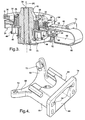
- Figure 3 is a perspective view cut away and in cross section of the assembly shown in Figures 1 and 2,
- Figure 4 is a perspective view of the sensor casing of the subject invention;
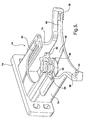
- Figure 5 is a perspective view of the sensor casing from the opposite direction than the directional view in Figure 4;
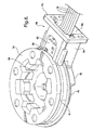
- Figure 6 is a perspective view of the sensor casing from the bottom and associated with part of the assembly;
- Figure 7 is a perspective view of the sensor casing from the top and associated with part of the assembly;
- Figure 8 is an exploded perspective view of the assembly but showing a slightly different configuration of the sensor casing arms; and
- Figure 9 is a perspective view of the assembly shown in Figure 8 supported in a vehicle structure.
- An assembly for measuring the relative rotational movement between an
input shaft 16 and anoutput shaft 18 and for measuring the angular position of the shafts is generally shown in Figures 1-3. The assembly includes asupport housing 20 including bearings 22 for rotatably supporting theoutput shaft 18 for rotation about an axis A. Theoutput shaft 18 axially aligned with and supported by theinput shaft 16 for rotation about the axis A. Atorsion bar 24 interconnects theshafts shafts input shaft 16 is coupled to a steering wheel (not shown). Theoutput shaft 18 is coupled to a steering system (not shown), for example, a rack and pinion gear mechanism. The entire assembly is more specifically described in application serial number XX/XXX,XXX attorney number (DP-311735} filed on January 14, 2005, and will be briefly described here. - The assembly includes a torque probe comprising a pair of
torque sensors 26 for sensing a signal indicative of relative rotational movement between theinput shaft 16 and theoutput shaft 18. Atorque rotor 28 is rotated by theinput shaft 16 and supports sixmagnets 30 in six circumferentially spaced pockets on the outer surface of thetorque rotor 28 with aretainer ring 32 retaining themagnets 30 in the pockets. - A
torque wheel 34 is rotated by theoutput shaft 18 and supports a pair of axially spacedtorque stators 36 that are angularly offset or out of phase with each other. The axial displacement between thetorque stators 36 defines a gap (G) for establishing a measurement zone through which the magnetic flux from the plurality ofmagnets 30 passes. Thetorque sensors 26 measure the magnetic flux generated by themagnets 30. As suggested above, thetorque stators 36 are offset or out of phase with each other by way of radially inwardly directed torque. The magnetic flux measured by thetorque sensors 26 varies depending on the alignment of themagnets 30 in thetorque wheel 34 and the torque projections of thetorque stators 36. The magnetic flux generated by eachmagnet 30 flows through thetorque stators 36 to create a differential magnetic flux between the twotorque stators 36 which flows through the gap (G) between thetorque stators 36 and is sensed by thetorque sensors 26. This differential magnetic flux is indicative of the relative or differential rotational movement between theinput shaft 16 and theoutput shaft 18. At a no-load torque condition, both of thetorque stators 36 produce the same amount of flux, hence the differential flux crossing through the gap (G) is zero. - A position probe comprising a pair of
position sensors 38 sense a signal indicative of the angular position of at least one of theshafts output shaft 18 between any angle of and degrees. More specifically, thetorque wheel 34 also supports amagnetic ring 40 that is axially spaced from thetorque stators 36 by a dependingskirt 42. Themagnetic ring 40 rotates with thetorque wheel 34 to generate a magnetic flux which corresponds to the incremental angle of theoutput shaft 18. Theposition sensors 38 detect the magnetic flux of themagnetic ring 40. - As will be described more fully herein after, a
sensor casing 44 supports thetorque sensors 26 of the torque probe and theposition sensors 38 of the position probe and is removably attached to thesupport housing 20 for detaching the torque probe and the position probe from the assembly. In addition, thesensor casing 44 supports a segment probe that includes a pair of segment magneto-sensitive elements 46 to provide a segment output indicative of the angular segment in which theshafts position sensors 38 may determine the angle of rotation in a given revolution, i.e., between zero and three hundred and sixty degrees, but can not determine the number of revolutions or in which revolution theshafts shafts change gear 48 rotatably supported by thesensor casing 44 for rotation through predetermined angular segments in response to rotation of thetorque wheel 34. As best shown in Figure 7, thesensor casing 44 includes a boss rotatably supporting and extending downwardly from thechange gear 48. - The
change gear 48 includes a plurality offirst teeth 50 disposed in a first plane and a plurality ofsecond teeth 52 disposed in a second plane spaced axially from the first plane with thefirst teeth 50 and thesecond teeth 52 being angularly offset and out of phase with each other. Thetorque wheel 34 includes a pair ofblocking cams 54 in axially spaced planes corresponding to the planes of theteeth change gear 48 with eachblocking cam 54 extending half way around thetorque wheel 34, i.e., one hundred and eighty degrees. A pair ofabutments 56 between the ends of the blockingcams 54 engages theteeth change gear 48 to rotate thechange gear 48 in segments of a revolution. Amagnetic segment 58 is carried by the post of thechange gear 48 to provide magnetic flux sensed by the segment magneto-sensitive elements 46. Accordingly, the position of thechange gear 48 is indicative of the revolution in which theoutput shaft 18 is disposed. - A circuit board is U-shaped between a
position leg 60 and atorque leg 62. Thesensor casing 44 includes a pair of opposing guide-ways 64 and thetorque leg 62 of the circuit board slides into and extends between the guide-ways 64. Thesensor casing 44 also includes agear platform 66 having a top surface and a bottom surface extending parallel to and spaced from the guide-ways 64 and theposition leg 60 of the circuit board slides over and is supported on the bottom surface of thegear platform 66. Thechange gear 48 is rotatably supported on thegear platform 66 and extends from the top surface toward the guide-ways 64. Accordingly, the segment probe interacts between theposition leg 60 and thechange gear 48 for providing a segment output indicative of the angular segment in which thetorque wheel 34 is disposed. Thetorque leg 62 of the circuit board extends from the guide-ways 64 to a leading edge and thetorque sensor 26 is disposed on that leading edge of the circuit board. - The
sensor casing 44 includes a pair of casingarms 68 extending in opposite directions in a circular path from thegear platform 66 to distal ends. Theposition leg 60 of the circuit board includes a pair ofcircuit arms 70 extending in opposite directions in the same circular path to underlie the bottom surface of the casingarms 68 of thegear platform 66. Theposition sensors 38 are supported on thecircuit arms 70 and extend upwardly throughopenings 72 in the casingarms 68. - The
sensor casing 44 includes a mountingflange 74 removably attached to thesupport housing 20 by fasteners that threadedly engage thesupport housing 20. Thegear platform 66 and the guide-ways 64 extend from the mountingflange 74 and include a top wall interconnecting the guide-ways 64 andside walls 76 interconnecting the top wall and thegear platform 66 to define an access in the flange through which electrical leads 78 are disposed. - The
sensor casing 44 forms the basis of a probe module for a modular sensing assembly for measuring the relative rotational movement between aninput shaft 16 and anoutput shaft 18 and for measuring the angular position of the shafts relative to asupport housing 20, and for providing a segment output indicative of the angular segment in which the shafts are disposed. The mountingflange 74 facilitates the attachment and removal of all of the electrical components from the steering column for repair and/or replacement. - The assembly shown in Figures 8 and 9 is essentially the same as that shown in the previous Figures except for a slightly different configuration of the casing
arms 68 and placement of thetorque sensors 26 and theposition sensors 38. More specifically, theposition sensors 38 are disposed along the casingarms 68 and thetorque sensors 26 are supported on risers or fingers 80 extending upwardly from the distal ends of the casingarms 68. In addition, the electrical leads 78 extend from the side of thesensor casing 44. Thetorque sensors 26 and theposition sensors 38 are respectively mounted onflexboard 82 that is like circuit board and that may be heat staked tosensor casing 44 byintegral stakes 84 that are softened with heat to lock theflexboard 82 in place. - Obviously, many modifications and variations of the present invention are possible in light of the above teachings. It is, therefore, to be understood that within the scope of the appended claims, the invention may be practiced otherwise than as specifically described. The invention is defined by the claims.
Claims (29)
- A probe module for a position detection assembly for measuring the relative rotational movement between an input shaft (16) and an output shaft (18) and for measuring the angular position of said shaftsrelative to a support housing (20), said probe module comprising;a torque probe for sensing a signal indicative of relative rotational movement between the input shaft (16) and the output shaft (18),a position probe for sensing a signal indicative of the angular position of one of the shafts ( 16, 18);a sensor casing (44) for removable attachment to the support housing (20) and supporting said torque probe and said position probe.
- An assembly as set forth in claim 1 including a segment probe supported on said sensor casing (44) for providing a segment output indicative of the angular segment in which said shaftsare disposed.
- A probe module as set forth in claim 2 including a change gear (48) rotatably supported by said sensor casing (44) for rotation through predetermined angular segments in response to rotation of the shafts ( 16,18).
- A probe module as set forth in claim 3 wherein said segment probe is responsive to said change gear (48) for providing a segment output indicative of the angular segment in which said change gear (48) is disposed.
- A probe module as set forth in claim 4 wherein said segment probe includes a segment magnet (30) rotated by said change gear (48) for providing a magnetic flux indicative of the angular segment in which said change gear (48) is disposed.
- A probe module as set forth in claim 5 wherein said segment probe includes at least one segment magneto-sensitive element (46) supported on said sensor casing (44) for detecting the magnetic flux of said segment magnet (30) to provide a segment output indicative of the angular segment in which the change gear (48) is disposed.
- A probe module as set forth in claim 3 including a circuit board supporting said torque probe and said position probe.
- A probe module as set forth in claim 7 wherein said sensor casing (44) includes a pair of opposing guide-ways (64) and said circuit board includes a torque leg (62) extending between said guide-ways (64).
- A probe module as set forth in claim 8 wherein said sensor casing (44) includes a gear platform (66) having a top surface and a bottom surface and extending parallel to and spaced from said guide-ways (64), said change gear (48) being rotatably supported on said gear platform (66) and extending from said top surface toward said guide-ways (64).
- A probe module as set forth in claim 9 wherein said circuit board includes a position leg (60) supported on said bottom surface of said gear platform (66), a segment probe interacting between said position leg (60) and said change gear (48) for providing a segment output indicative of the angular segment in which said change gear (48) is disposed.
- A probe module as set forth in claim 3 wherein said sensor casing (44) includes a gear platform (66) having a top surface and a bottom surface, said change gear (48) being rotatably supported on said gear platform (66) and extending from said top surface, a segment magnet (30) rotated by said change gear (48) for providing a magnetic flux indicative of the angular segment in which said change gear (48) is disposed and at least one segment magneto-sensitive element (46) supported on said casing for detecting the magnetic flux of said segment magnet (30) to provide a segment output indicative of the angular segment in which the change gear (48) is disposed..
- A probe module as set forth in claim 10 wherein said circuit board is U-shaped between said torque leg (62) disposed in said guide-ways (64) and said position leg (60) engaging said bottom surface of said gear platform (66).
- A probe module as set forth in claim 11 wherein said sensor casing (44) includes a pair of casing arms (68) extending in opposite directions in a circular path from said gear platform (66) to distal ends.
- A probe module as set forth in claim 13 wherein said position leg (60) includes a pair of circuit arms (70) extending in opposite directions in said circular path to underlie said bottom surface of said casing arms (68) of said gear platform (66).
- A probe module as set forth in claim 14 wherein said sensor casing (44) includes a mounting flange (74) for removably attaching said sensor casing (44) to a support housing (20), said gear platform (66) and said guide-ways (64) extending from said mounting flange (74) and including a top wall interconnecting said guide-ways (64) and side walls (76) interconnecting said top wall and said gear platform (66) to define an access in said mounting flange (74).
- A probe module as set forth in claim 13 wherein said change gear (48) includes a plurality of first teeth (50) disposed in a first plane and a plurality of second teeth (52) disposed in a second plane spaced axially from said first plane with said first teeth (50) and said second teeth (52) being angularly offset and out of phase with each other.
- A probe module as set forth in claim 13 wherein said position probe includes a position sensor (38) on each of said casing arms (68).
- A probe module as set forth in claim 14 wherein said torque leg (62) of said circuit board extends from said guide-ways (64) to a leading edge and said torque probe includes a torque sensor (26) on said leading edge of said circuit board.
- An assembly for measuring the relative rotational movement between an input shaft (16) and an output shaft (18) and for measuring the angular position of said shafts ( 16, 18), said assembly comprising:an input shaft (16);an output shaft (18) axially aligned with said input shaft (16) for rotation about said axis;a support housing (20) for rotatably supporting said output shaft (18) for rotation about an axis;a torsion bar (24) interconnecting said shaftsfor allowing relative rotational movement between said shaftsin response to a predetermined torque,a torque probe for sensing a signal indicative of relative rotational movement between said input shaft (16) and said output shaft (18),a position probe sensing a signal indicative of the angular position of one of said shafts (16, 18); anda sensor casing (44) supporting said torque probe and said position probe and removably attached to said support housing (20) for detaching said torque probe and said position probe from said assembly.
- An assembly as set forth in claim 19 including a segment probe supported on said sensor casing (44) for providing a segment output indicative of the angular segment in which said shaftsare disposed.
- An assembly as set forth in claim 20 including a change gear (48) rotatably supported by said sensor casing (44) for rotation through predetermined angular segments in response to rotation of said shafts ( 16, 18).
- An assembly as set forth in claim 21 including a circuit board supporting said torque probe and said position probe.
- An assembly as set forth in claim 22 wherein said sensor casing (44) includes a pair of opposing guide-ways (64) and said circuit board includes a torque leg (62) extending between said guide-ways (64).
- An assembly as set forth in claim 21 wherein said sensor casing (44) includes a gear platform (66) having a top surface and a bottom surface, said change gear (48) being rotatably supported on said gear platform (66) and extending from said top surface.
- An assembly as set forth in claim 24 wherein said circuit board includes a position leg (60) supported on said bottom surface of said gear platform (66), a segment probe interacting between said position leg (60) and said change gear (48) for providing a segment output indicative of the angular segment in which said change gear (48) is disposed.
- An assembly as set forth in claim 25 wherein said circuit board is U-shaped between said torque leg (62) disposed in said guide-ways (64) and said position leg (60) engaging said bottom surface of said gear platform (66).
- An assembly as set forth in claim 24 wherein said sensor casing (44) includes a pair of casing arms (68) extending in opposite directions in a circular path from said gear platform (66) to distal ends.
- An assembly as set forth in claim 27 wherein said position leg (60) includes a pair of circuit arms (70) extending in opposite directions in said circular path to underlie said bottom surface of said casing arms (68) of said gear platform (66).
- An assembly as set forth in claim 27 wherein said sensor casing (44) includes a mounting flange (74) removably attached to said support housing (20), said gear platform (66) and including a top wall and side walls (76) interconnecting said top wall and said gear platform (66) to define an opening (72) in said flange.
Applications Claiming Priority (1)
| Application Number | Priority Date | Filing Date | Title |
|---|---|---|---|
| US11/053,329 US7363825B2 (en) | 2005-02-08 | 2005-02-08 | Non-contact position sensor housing using existing torque sensor probe |
Publications (1)
| Publication Number | Publication Date |
|---|---|
| EP1688729A1 true EP1688729A1 (en) | 2006-08-09 |
Family
ID=36498902
Family Applications (1)
| Application Number | Title | Priority Date | Filing Date |
|---|---|---|---|
| EP06075220A Withdrawn EP1688729A1 (en) | 2005-02-08 | 2006-01-31 | Non-contact position sensor housing using existing torque sensor probe |
Country Status (2)
| Country | Link |
|---|---|
| US (1) | US7363825B2 (en) |
| EP (1) | EP1688729A1 (en) |
Cited By (4)
| Publication number | Priority date | Publication date | Assignee | Title |
|---|---|---|---|---|
| EP2314499A1 (en) * | 2009-10-21 | 2011-04-27 | Kayaba Industry Co., Ltd. | Power Steering Device |
| CN102419228A (en) * | 2010-09-27 | 2012-04-18 | 伯恩斯公司 | Three-piece torque sensor assembly |
| CN110702406A (en) * | 2019-11-01 | 2020-01-17 | 大连宝信起重技术有限公司 | Abnormal detection equipment for crane speed reducer |
| CN112212780A (en) * | 2019-07-09 | 2021-01-12 | 株式会社捷太格特 | sensor device |
Families Citing this family (20)
| Publication number | Priority date | Publication date | Assignee | Title |
|---|---|---|---|---|
| JP4567565B2 (en) * | 2005-09-27 | 2010-10-20 | 本田技研工業株式会社 | Electric power steering device |
| KR200470045Y1 (en) * | 2008-12-16 | 2013-11-25 | 엘지이노텍 주식회사 | Electric power steering system |
| FR2947902B1 (en) | 2009-07-07 | 2011-07-22 | Moving Magnet Technologies M M T | ABSOLUTE AND MULTI-PERIODIC POSITION SENSOR |
| FR2952430B1 (en) | 2009-11-06 | 2012-04-27 | Moving Magnet Technologies M M T | BIDIRECTIONAL MAGNETIC POSITION SENSOR WITH FIELD ROTATION |
| US8390276B2 (en) | 2010-09-27 | 2013-03-05 | Bourns Incorporated | Target magnet assembly for a sensor used with a steering gear |
| FR2965347B1 (en) | 2010-09-29 | 2015-04-03 | Moving Magnet Tech | IMPROVED POSITION SENSOR |
| DE102011002563A1 (en) * | 2010-12-20 | 2012-06-21 | Robert Bosch Gmbh | sensor arrangement |
| WO2012162603A1 (en) * | 2011-05-25 | 2012-11-29 | Wabash Technologies, Inc. | Magnetic position sensor assembly for measurement of rotational angular position of a rotating structure |
| US8776619B2 (en) | 2011-11-18 | 2014-07-15 | Bourns, Inc. | Small angle sensor for measuring steering shaft torque |
| US8746082B2 (en) * | 2012-05-08 | 2014-06-10 | Ksr Ip Holdings Llc | Torque sensor |
| KR102055800B1 (en) * | 2013-09-27 | 2019-12-13 | 엘지이노텍 주식회사 | Torque sensor |
| JP6209476B2 (en) * | 2014-03-27 | 2017-10-04 | 株式会社ショーワ | Sensor unit, torque detection device, and electric power steering device |
| DE102014218717A1 (en) * | 2014-09-17 | 2016-03-17 | Continental Teves Ag & Co. Ohg | SAS backlash-free drive |
| JP6330178B2 (en) * | 2014-11-19 | 2018-05-30 | 日立金属株式会社 | Torque steering angle sensor |
| US10794780B2 (en) * | 2015-10-08 | 2020-10-06 | Steering Solutions Ip Holding Corporation | Magnetic support structure of a torque sensor assembly including a central hub and a plurality of spoke segments extending radially outwardly from the central hub |
| WO2018124723A1 (en) | 2016-12-28 | 2018-07-05 | 엘지이노텍 주식회사 | Torque sensor and steering apparatus including same |
| JP6939385B2 (en) * | 2017-10-13 | 2021-09-22 | 株式会社ジェイテクト | Sensor device |
| DE102020209463A1 (en) * | 2020-07-28 | 2022-02-03 | Zf Friedrichshafen Ag | Steering system and sensor module for a steering system |
| JP7494819B2 (en) * | 2021-08-24 | 2024-06-04 | 株式会社デンソー | Torque detector |
| WO2023068068A1 (en) * | 2021-10-22 | 2023-04-27 | 株式会社デンソー | Torque detection system |
Citations (5)
| Publication number | Priority date | Publication date | Assignee | Title |
|---|---|---|---|---|
| GB643823A (en) * | 1948-05-11 | 1950-09-27 | Henry George Yates | Improvements in or relating to torque measuring devices |
| US20030102181A1 (en) * | 2001-11-30 | 2003-06-05 | Yoshitomo Tokumoto | Electric power steering apparatus |
| US6578437B1 (en) * | 1998-08-07 | 2003-06-17 | Robert Bosch Gmbh | Sensor array for detecting rotation angle and/or torque |
| EP1342646A2 (en) * | 2002-03-05 | 2003-09-10 | Alps Electric Co., Ltd. | Rotation-angle detecting device capable of detecting absolute angle with simple configuration |
| EP1541983A1 (en) * | 2003-09-02 | 2005-06-15 | Matsushita Electric Industrial Co., Ltd. | Device for detecting rotation angle and torque |
Family Cites Families (9)
| Publication number | Priority date | Publication date | Assignee | Title |
|---|---|---|---|---|
| JPS6014659B2 (en) * | 1979-10-03 | 1985-04-15 | ブラザー工業株式会社 | Step feed device in machine tools |
| KR890000890A (en) * | 1987-06-22 | 1989-03-17 | 미타 가츠시게 | Torque Detection Device |
| US5404775A (en) * | 1994-03-11 | 1995-04-11 | Sanyo Machine | Right angle fastening device |
| US5544526A (en) * | 1994-06-30 | 1996-08-13 | Avionics Specialties, Inc. | Combined aircraft angle of attack and dynamic/static pressure sensor assembly |
| JP3139612B2 (en) * | 1996-05-21 | 2001-03-05 | 本田技研工業株式会社 | Electric power steering apparatus and electric power steering assembly method |
| US5828136A (en) * | 1996-07-23 | 1998-10-27 | Yang; Tai-Her | Combined power system using a rotation speed and torque detector |
| US6430952B1 (en) * | 1997-04-18 | 2002-08-13 | Bun-O-Matic Corporation | Cold drink system |
| US6820713B2 (en) * | 2002-07-17 | 2004-11-23 | Delphi Technologies, Inc. | Hand wheel actuator with steering-feel enhancement |
| US7174795B2 (en) * | 2004-02-06 | 2007-02-13 | Delphi Technologies, Inc. | Integrated non-contacting torque and absolute position sensor for steering applications |
-
2005
- 2005-02-08 US US11/053,329 patent/US7363825B2/en not_active Expired - Fee Related
-
2006
- 2006-01-31 EP EP06075220A patent/EP1688729A1/en not_active Withdrawn
Patent Citations (5)
| Publication number | Priority date | Publication date | Assignee | Title |
|---|---|---|---|---|
| GB643823A (en) * | 1948-05-11 | 1950-09-27 | Henry George Yates | Improvements in or relating to torque measuring devices |
| US6578437B1 (en) * | 1998-08-07 | 2003-06-17 | Robert Bosch Gmbh | Sensor array for detecting rotation angle and/or torque |
| US20030102181A1 (en) * | 2001-11-30 | 2003-06-05 | Yoshitomo Tokumoto | Electric power steering apparatus |
| EP1342646A2 (en) * | 2002-03-05 | 2003-09-10 | Alps Electric Co., Ltd. | Rotation-angle detecting device capable of detecting absolute angle with simple configuration |
| EP1541983A1 (en) * | 2003-09-02 | 2005-06-15 | Matsushita Electric Industrial Co., Ltd. | Device for detecting rotation angle and torque |
Cited By (11)
| Publication number | Priority date | Publication date | Assignee | Title |
|---|---|---|---|---|
| EP2314499A1 (en) * | 2009-10-21 | 2011-04-27 | Kayaba Industry Co., Ltd. | Power Steering Device |
| CN102039930A (en) * | 2009-10-21 | 2011-05-04 | 萱场工业株式会社 | Power steering device |
| JP2011088507A (en) * | 2009-10-21 | 2011-05-06 | Kyb Co Ltd | Power steering device |
| US8534141B2 (en) | 2009-10-21 | 2013-09-17 | Kayaba Industry Co., Ltd. | Power steering device |
| CN102039930B (en) * | 2009-10-21 | 2014-04-23 | 萱场工业株式会社 | Power steering device |
| CN102419228A (en) * | 2010-09-27 | 2012-04-18 | 伯恩斯公司 | Three-piece torque sensor assembly |
| CN102419228B (en) * | 2010-09-27 | 2014-12-17 | 伯恩斯公司 | Three-piece torque sensor assembly |
| CN112212780A (en) * | 2019-07-09 | 2021-01-12 | 株式会社捷太格特 | sensor device |
| EP3764071A1 (en) * | 2019-07-09 | 2021-01-13 | Jtekt Corporation | Sensor device |
| US11300464B2 (en) | 2019-07-09 | 2022-04-12 | Jtekt Corporation | Sensor device |
| CN110702406A (en) * | 2019-11-01 | 2020-01-17 | 大连宝信起重技术有限公司 | Abnormal detection equipment for crane speed reducer |
Also Published As
| Publication number | Publication date |
|---|---|
| US7363825B2 (en) | 2008-04-29 |
| US20060236784A1 (en) | 2006-10-26 |
Similar Documents
| Publication | Publication Date | Title |
|---|---|---|
| US7363825B2 (en) | Non-contact position sensor housing using existing torque sensor probe | |
| KR101497740B1 (en) | Non-contact multi-turn absolute position magnetic sensor comprising a through-shaft | |
| US12134434B2 (en) | Torque sensor, steering angle sensor and corresponding integrated sensor and monitoring system | |
| US7366636B2 (en) | Rotational angle detector | |
| EP2314499B1 (en) | Power Steering Device | |
| EP2674728A2 (en) | Rotation angle sensor | |
| US20100319467A1 (en) | Inductive torque sensor | |
| CN102564297A (en) | Sensor system | |
| CN101508310A (en) | Device for determining a torsion angle | |
| KR101359347B1 (en) | Torque sensor for steering system using an absolute phase angle detection | |
| US9057652B2 (en) | Torque detecting apparatus | |
| SE546175C2 (en) | A steer-by-wire steering assembly | |
| US7201070B2 (en) | Rotational angle detecting apparatus and torque detecting apparatus | |
| CN106794872B (en) | Torque sensor device | |
| KR101859768B1 (en) | Torque Index Sub Angle Sensor | |
| WO2006087627A1 (en) | Monitoring device | |
| JP2004264155A (en) | Rotating angle detecting device and torque detecting device | |
| KR20130128549A (en) | Angle sensor | |
| KR102264315B1 (en) | Multi-turn Absolute Torque Angle Sensor Module | |
| WO2023195906A1 (en) | A steer-by-wire steering assembly | |
| WO2023195900A1 (en) | A steer-by-wire steering assembly | |
| WO2023195904A1 (en) | A steer-by-wire steering assembly | |
| WO2023195902A1 (en) | A steer-by-wire steering assembly | |
| EP4504575A1 (en) | A steer-by-wire steering assembly | |
| WO2023195905A1 (en) | A steer-by-wire steering assembly |
Legal Events
| Date | Code | Title | Description |
|---|---|---|---|
| PUAI | Public reference made under article 153(3) epc to a published international application that has entered the european phase |
Free format text: ORIGINAL CODE: 0009012 |
|
| AK | Designated contracting states |
Kind code of ref document: A1 Designated state(s): AT BE BG CH CY CZ DE DK EE ES FI FR GB GR HU IE IS IT LI LT LU LV MC NL PL PT RO SE SI SK TR |
|
| AX | Request for extension of the european patent |
Extension state: AL BA HR MK YU |
|
| 17P | Request for examination filed |
Effective date: 20070209 |
|
| AKX | Designation fees paid |
Designated state(s): AT BE BG CH CY CZ DE DK EE ES FI FR GB GR HU IE IS IT LI LT LU LV MC NL PL PT RO SE SI SK TR |
|
| 17Q | First examination report despatched |
Effective date: 20070319 |
|
| RAP1 | Party data changed (applicant data changed or rights of an application transferred) |
Owner name: GM GLOBAL TECHNOLOGY OPERATIONS, INC. |
|
| RAP1 | Party data changed (applicant data changed or rights of an application transferred) |
Owner name: GM GLOBAL TECHNOLOGY OPERATIONS LLC |
|
| RAP1 | Party data changed (applicant data changed or rights of an application transferred) |
Owner name: GM GLOBAL TECHNOLOGY OPERATIONS LLC Owner name: STEERING SOLUTIONS IP HOLDING CORPORATION |
|
| STAA | Information on the status of an ep patent application or granted ep patent |
Free format text: STATUS: THE APPLICATION IS DEEMED TO BE WITHDRAWN |
|
| 18D | Application deemed to be withdrawn |
Effective date: 20150801 |