EP1688530A1 - Clothes washing machine with improved filter assembly - Google Patents
Clothes washing machine with improved filter assembly Download PDFInfo
- Publication number
- EP1688530A1 EP1688530A1 EP05100868A EP05100868A EP1688530A1 EP 1688530 A1 EP1688530 A1 EP 1688530A1 EP 05100868 A EP05100868 A EP 05100868A EP 05100868 A EP05100868 A EP 05100868A EP 1688530 A1 EP1688530 A1 EP 1688530A1
- Authority
- EP
- European Patent Office
- Prior art keywords
- final length
- washing machine
- length
- clothes washing
- drain
- Prior art date
- Legal status (The legal status is an assumption and is not a legal conclusion. Google has not performed a legal analysis and makes no representation as to the accuracy of the status listed.)
- Granted
Links
- 238000005406 washing Methods 0.000 title claims abstract description 24
- 238000001914 filtration Methods 0.000 claims abstract description 28
- 230000005484 gravity Effects 0.000 description 5
- 230000000717 retained effect Effects 0.000 description 3
- 238000004140 cleaning Methods 0.000 description 2
- 239000002245 particle Substances 0.000 description 2
- 235000010585 Ammi visnaga Nutrition 0.000 description 1
- 244000153158 Ammi visnaga Species 0.000 description 1
- 101150114468 TUB1 gene Proteins 0.000 description 1
- 230000004931 aggregating effect Effects 0.000 description 1
- 238000010276 construction Methods 0.000 description 1
- 230000007423 decrease Effects 0.000 description 1
- 238000007599 discharging Methods 0.000 description 1
- 239000004744 fabric Substances 0.000 description 1
- 239000012634 fragment Substances 0.000 description 1
- 239000007788 liquid Substances 0.000 description 1
- 238000004513 sizing Methods 0.000 description 1
- 238000011144 upstream manufacturing Methods 0.000 description 1
Images




Classifications
-
- D—TEXTILES; PAPER
- D06—TREATMENT OF TEXTILES OR THE LIKE; LAUNDERING; FLEXIBLE MATERIALS NOT OTHERWISE PROVIDED FOR
- D06F—LAUNDERING, DRYING, IRONING, PRESSING OR FOLDING TEXTILE ARTICLES
- D06F39/00—Details of washing machines not specific to a single type of machines covered by groups D06F9/00 - D06F27/00
- D06F39/10—Filtering arrangements
Definitions
- the present invention refers to an improved kind of clothes washing machine, preferably of the type intended for use in households, provided with a particularly efficient filter unit for the protection of the impeller of the drain pump.
- Clothes washing machines are generally known are provided with a drain pump comprised of an impeller driven by a related electric motor; this impeller is usually housed in a corresponding drain chamber, in which there debouches a conduit extending from the bottom of the wash tub to convey the liquor to be let off into said drain chamber, and from which there departs a drain conduit that, usually through a siphon-shaped length of pipe, conveys said liquor outside the machine.
- a particular filtering arrangement or more simply a filter, as it will be referred to hereinafter, with the task of intercepting and retaining coarse foreign matters that may be contained in the liquor flowing in from the tub.
- these foreign matter are quite likely to end up by aggregating to, i.e. clogging the impeller, thereby causing the whole pump to become stalled.
- a tub 1 holding the washload i.e. the clothes to be washed
- a drain pipe 2 that branches off, with its upper portion, from the bottom of said tub and connects the latter with a drain pump chamber 3 located at the lower end portion thereof; by its own nature, said drain pipe is at least partially oriented downwards, since it must collect the liquid flowing from the bottom of the tub by gravity, and it comprises a central portion 15, which is inclined or oriented downwards, and a final portion or length 5 that joins with said drain pump chamber 3 and extends in a substantially horizontal manner.
- a hydraulic impeller 4 driven by an electric motor (not shown).
- the drain filter is arranged in series with the flowpath of the liquor being conveyed through said drain pipe and reaching said impeller and, hence, it lies either in the drain pipe itself or within the drain pump chamber 3.
- the filter is not arranged in series to the flowpath of the liquor, but rather in parallel thereto; in particular, it is arranged in parallel to said final length 5, in a zone lying therebeneath.
- said filter does by no means require to be made in any special manner whatsoever, but is most simply constituted by a pocket 6, which is closed at an end portion thereof and works as an auxiliary filtering chamber; the latter is open upwards through an aperture 7, which connects it to an opening in the bottom wall 10 of said final length 5 of pipe. Thanks to the particular location thereof and the provision of said vertically oriented aperture 7, said auxiliary filtering chamber 6 is able to spontaneously intercept, retain and collect any foreign body and matter that may be carried in the flow of the liquor being let out, since these bodies and matters carried by said liquor simply fall thereinto by gravity when passing by said aperture 7.
- said auxiliary filtering chamber 6 must be situated, i.e. lie underneath said final length 5 of pipe, which in turn must in a preferred way be horizontal, but may be also inclined, although this would of course reduce its effectiveness, since the cross-sectional area on the horizontal plane of the aperture 7, which is what really matters for the force of gravity to be able to work in the due manner, decreases with the inclination of said aperture approaching the vertical.
- an improved embodiment of said auxiliary filtering chamber 6 is provided by having said aperture 7 situated at the beginning of said final length of pipe, as well as by sizing said auxiliary filtering chamber 6 so that it extends forwards from said aperture 7 in the direction of and under said final length of pipe, so as to be able to make the most out of the internal volume thereof, since the objects that fall thereinto by gravity obviously have a velocity component in the direction of said final length of pipe and, hence, they tend to spontaneously heap up therebelow.
- a further improved embodiment of said auxiliary filtering chamber 6 consists in giving it a shape so that the bottom wall 8 thereof joins with a smooth radius 9 with the remaining part of said drain pipe 2, wherein the wall 20 of the latter acts in particular so as to partially delimit said aperture 7; this improvement, in fact, creates a concavity towards the interior of the central length 15 of the drain pipe, or towards the portion thereof that joins with the final length of the same drain pipe, so as to make it easier for lighter objects and matters to be intercepted and retained within said auxiliary chamber 6, owing to said aperture 7 being in this way significantly enlarged; in addition, the eddy or vortex V forming towards the bottom, immediately downstream of the corner 17 between said central length 15 of the drain pipe and the vertical portion 18 of the auxiliary chamber 6, as this is best shown schematically in Figure 2, is eliminated.
- the present invention might substantially be represented also in the form of a drain manifold or pipe 2, which grows sensibly larger as it moves downwards, while being however provided in its terminal portion with an intermediate wall 28 that cuts it horizontally, so as to separate said drain pipe into two distinct cavities lying upon each other, wherein the upper cavity corresponds to the final length 5 of the pipe flowing into the drain pump chamber 3 and the lower cavity forms the above-mentioned auxiliary filtering chamber 6.
- auxiliary filtering chamber 6 consists in providing a drain manifold or pipe 2 which has, in its final length, an inside cross-sectional area S that is suitably increased as compared with the inflow mouth E of the drain pump chamber 3, while arranging around said inflow mouth E a cylindrical member 19 that:
- said drain pipe and said cylindrical member are two substantially cylindrical elements having parallel, but not coaxial axes, in which said final length 5 comes to be situated substantially outside said cylindrical member 19.
- the cavity forming between said drain pipe 2 and said cylindrical member 19 contained therein takes the form of an elongated, horizontally extending "crown", thereby providing in an easy and reliable manner an improved embodiment of said auxiliary filtering chamber 6.
- the advantage of this construction lies in the fact that said auxiliary filtering chamber becomes in this way much more effective in intercepting and retaining not only the heavier bodies and matters that that tend naturally to collect downwards onto the bottom, but also smaller and, therefore, lighter matters and particles, such as buttons, toothpicks, fabric fragments, and the like, which on the contrary do not tend to unfailingly fall downwards, so that they would not be reliably intercepted with the other embodiments of the present invention, but are on the contrary more easily and effectively caught and retained by said auxiliary filtering chamber having the above-described crown-like shape.
- said horizontal cylinder 19 is positioned in the upper portion of said final length of drain pipe, so that its axis X extends substantially parallel to, but at a higher level than the axis Y of said final length 5; this enables said auxiliary filtering chamber 6 to preserve a good intercepting, retaining and collecting ability as far as the heavier foreign bodies and matters are concerned, which are the majority of the debris in the liquor being let off a washing tub, while anyway ensuring a good effectiveness in intercepting and retaining also lighter bodies and matters that are generally found at the periphery of the flow of liquor moving down said drain pipe 2.
Landscapes
- Engineering & Computer Science (AREA)
- Textile Engineering (AREA)
- Detail Structures Of Washing Machines And Dryers (AREA)
- Structures Of Non-Positive Displacement Pumps (AREA)
Abstract
Description
- The present invention refers to an improved kind of clothes washing machine, preferably of the type intended for use in households, provided with a particularly efficient filter unit for the protection of the impeller of the drain pump.
- Clothes washing machines are generally known are provided with a drain pump comprised of an impeller driven by a related electric motor; this impeller is usually housed in a corresponding drain chamber, in which there debouches a conduit extending from the bottom of the wash tub to convey the liquor to be let off into said drain chamber, and from which there departs a drain conduit that, usually through a siphon-shaped length of pipe, conveys said liquor outside the machine.
- Within said drain chamber, or upstream thereof, there is generally provided a particular filtering arrangement, or more simply a filter, as it will be referred to hereinafter, with the task of intercepting and retaining coarse foreign matters that may be contained in the liquor flowing in from the tub. As a matter of fact, should these foreign matter fail to be intercepted and retained prior to reaching the impeller of the pump, they are quite likely to end up by aggregating to, i.e. clogging the impeller, thereby causing the whole pump to become stalled.
- Various theories exist nowadays concerning such filter, each one of which is anyway the result of, i.e. is based on to two distinct and mutually contrasting filtering strategies:
- According to a first such strategy, said filter must be very efficient, i.e. as efficient as possible, so as to prevent any matter that may clog the impeller and cause the pump to stall from being capable of passing therethrough, while on the other hand enabling only minute, absolutely harmless particles to flow therethrough to be eventually discharged by the action of the same impeller; this strategy, however, has a drawback in that the filter, especially if the machine is used in a rather careless or incautious manner, will intercept and retain a lot of foreign bodies and matters I a very short time, thereby becoming soon clogged; it largely known that the ultimate consequence of such drawback is a failure of the machine to discharge the washing liquor and, practically, its becoming inoperative.
In view of doing away with this problem, or preventing it from occurring, the filter itself must therefore be removed and cleaned very frequently and this, of course, fives in turn rise to a number of drawbacks and risky situations, as any user of a washing machine is well aware of. - According to a second filtering strategy, the filter must be such as to be able to only intercept and retain those foreign bodies and matters that would surely cause the pump to stall, or anyway are quite likely to give rise to such problem, while allowing all other bodies and matters that are not so likely to clog and lock the pump to pass therethrough; it can be readily appreciated that advantages and disadvantages of this option are exactly the reverse of those encountered with the first strategy described above, in the sense that, in the second case, the filter will require less frequent cleaning (in certain cases, even much less frequent cleaning), whereas the pump may be expected to clog and stall - and therefore need servicing - rather frequently.
- Briefly, it can be stated that these kinds of problems tend substantially to arise owing to the filter being made in the form of a variously configured labyrinth arranged in series with the impeller, while then selecting between the two above-described strategies, neither of which can be regarded as being really the ideal one, i.e. opting for a rapidly clogging filter or a pump that is subject to frequent stalling.
- It would therefore be desirable, and it is actually a main object of the present invention, to provide a clothes washing machine that is provided with filtering means for the liquor flowing in from the washing tub in view of being discharged outside the machine, wherein said filtering means are very efficient, featuring excellent filtering properties for retaining even very small objects, as long as these objects are heavy, and, even if they are filled up with such objects, do not involve as a consequence either the need of being frequently cleaned or the risk of preventing the machine from draining, i.e. discharging the liquor in a correct and due manner.
- According to the present invention, these aims, along with further ones that shall be described further on, are reached in a clothes washing machine using a kind of drain filter that operates by gravity and is arranged in parallel to the flowpath of the liquor to be discharged, so as defined and recited in the appended claims.
- Anyway, features and advantages of the present invention will be more readily understood from the description that is given below by way of nonlimiting example with reference to the accompanying drawings, in which:
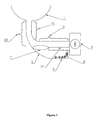
- Figure 1 is a median vertical sectional view of the drain pipe and the drain pump chamber in a first embodiment of a clothes washing machine according to the present invention;
- Figure 2 is a median vertical sectional view of the drain pipe and the drain pump chamber in a second embodiment of a clothes washing machine according to the present invention;
- Figure 3 is a median vertical sectional view of the drain pipe and the drain pump chamber in a third embodiment of a clothes washing machine according to the present invention;
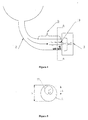
- Figure 4 is a median vertical sectional view of the drain pipe and the drain pump chamber in a fourth embodiment of a clothes washing machine according to the present invention;
- Figure 5 is a view along the orthogonal section A-A in Figure 4;
- Figure 6 is an outer perspective view of the filtering arrangement illustrated in Figures 4 and 5;
- Figure 7 is a view of a constructive variant of the embodiment illustrated in Figure 3;
- Figures 8 and 9 are side and cross-sectional views, respectively, of the arrangement shown in Figure 6.
- With reference to Figure 1, in a clothes washing machine according to the prior art there are provided a
tub 1 holding the washload, i.e. the clothes to be washed, adrain pipe 2 that branches off, with its upper portion, from the bottom of said tub and connects the latter with adrain pump chamber 3 located at the lower end portion thereof; by its own nature, said drain pipe is at least partially oriented downwards, since it must collect the liquid flowing from the bottom of the tub by gravity, and it comprises acentral portion 15, which is inclined or oriented downwards, and a final portion orlength 5 that joins with saiddrain pump chamber 3 and extends in a substantially horizontal manner. - Within said drain pump chamber there is provided, in a per se known manner, a
hydraulic impeller 4 driven by an electric motor (not shown). - According to the prior art, the drain filter is arranged in series with the flowpath of the liquor being conveyed through said drain pipe and reaching said impeller and, hence, it lies either in the drain pipe itself or within the
drain pump chamber 3. - In departure from this configuration, according to the present invention the filter is not arranged in series to the flowpath of the liquor, but rather in parallel thereto; in particular, it is arranged in parallel to said
final length 5, in a zone lying therebeneath. - For it to be capable of working, said filter does by no means require to be made in any special manner whatsoever, but is most simply constituted by a
pocket 6, which is closed at an end portion thereof and works as an auxiliary filtering chamber; the latter is open upwards through anaperture 7, which connects it to an opening in thebottom wall 10 of saidfinal length 5 of pipe. Thanks to the particular location thereof and the provision of said vertically orientedaperture 7, saidauxiliary filtering chamber 6 is able to spontaneously intercept, retain and collect any foreign body and matter that may be carried in the flow of the liquor being let out, since these bodies and matters carried by said liquor simply fall thereinto by gravity when passing by saidaperture 7. - To this purpose, said
auxiliary filtering chamber 6 must be situated, i.e. lie underneath saidfinal length 5 of pipe, which in turn must in a preferred way be horizontal, but may be also inclined, although this would of course reduce its effectiveness, since the cross-sectional area on the horizontal plane of theaperture 7, which is what really matters for the force of gravity to be able to work in the due manner, decreases with the inclination of said aperture approaching the vertical. - With reference to Figure 2, an improved embodiment of said
auxiliary filtering chamber 6 is provided by having saidaperture 7 situated at the beginning of said final length of pipe, as well as by sizing saidauxiliary filtering chamber 6 so that it extends forwards from saidaperture 7 in the direction of and under said final length of pipe, so as to be able to make the most out of the internal volume thereof, since the objects that fall thereinto by gravity obviously have a velocity component in the direction of said final length of pipe and, hence, they tend to spontaneously heap up therebelow. - With reference to Figure 3, a further improved embodiment of said
auxiliary filtering chamber 6 consists in giving it a shape so that thebottom wall 8 thereof joins with asmooth radius 9 with the remaining part of saiddrain pipe 2, wherein thewall 20 of the latter acts in particular so as to partially delimit saidaperture 7; this improvement, in fact, creates a concavity towards the interior of thecentral length 15 of the drain pipe, or towards the portion thereof that joins with the final length of the same drain pipe, so as to make it easier for lighter objects and matters to be intercepted and retained within saidauxiliary chamber 6, owing to saidaperture 7 being in this way significantly enlarged; in addition, the eddy or vortex V forming towards the bottom, immediately downstream of thecorner 17 between saidcentral length 15 of the drain pipe and thevertical portion 18 of theauxiliary chamber 6, as this is best shown schematically in Figure 2, is eliminated. - With reference to Figure 7, the present invention might substantially be represented also in the form of a drain manifold or
pipe 2, which grows sensibly larger as it moves downwards, while being however provided in its terminal portion with anintermediate wall 28 that cuts it horizontally, so as to separate said drain pipe into two distinct cavities lying upon each other, wherein the upper cavity corresponds to thefinal length 5 of the pipe flowing into thedrain pump chamber 3 and the lower cavity forms the above-mentionedauxiliary filtering chamber 6. - With reference to Figures 4 and 5, a further improved embodiment of said
auxiliary filtering chamber 6 consists in providing a drain manifold orpipe 2 which has, in its final length, an inside cross-sectional area S that is suitably increased as compared with the inflow mouth E of thedrain pump chamber 3, while arranging around said inflow mouth E acylindrical member 19 that: - is open at both bases thereof,
- has a base thereof applied against and around the rim of said inflow mouth E, and
- has its axis that extends substantially parallel to the axis of said
final length 5 of the drain pipe. - In practice, said drain pipe and said cylindrical member are two substantially cylindrical elements having parallel, but not coaxial axes, in which said
final length 5 comes to be situated substantially outside saidcylindrical member 19. - In this way, the cavity forming between said
drain pipe 2 and saidcylindrical member 19 contained therein takes the form of an elongated, horizontally extending "crown", thereby providing in an easy and reliable manner an improved embodiment of saidauxiliary filtering chamber 6. The advantage of this construction lies in the fact that said auxiliary filtering chamber becomes in this way much more effective in intercepting and retaining not only the heavier bodies and matters that that tend naturally to collect downwards onto the bottom, but also smaller and, therefore, lighter matters and particles, such as buttons, toothpicks, fabric fragments, and the like, which on the contrary do not tend to unfailingly fall downwards, so that they would not be reliably intercepted with the other embodiments of the present invention, but are on the contrary more easily and effectively caught and retained by said auxiliary filtering chamber having the above-described crown-like shape. - In an advantageous manner, said
horizontal cylinder 19 is positioned in the upper portion of said final length of drain pipe, so that its axis X extends substantially parallel to, but at a higher level than the axis Y of saidfinal length 5; this enables saidauxiliary filtering chamber 6 to preserve a good intercepting, retaining and collecting ability as far as the heavier foreign bodies and matters are concerned, which are the majority of the debris in the liquor being let off a washing tub, while anyway ensuring a good effectiveness in intercepting and retaining also lighter bodies and matters that are generally found at the periphery of the flow of liquor moving down saiddrain pipe 2.
Claims (7)
- Clothes washing machine comprising:- a clothes holding and washing tub (1),- a drain manifold or pipe (2) provided under said tub and connecting the internal volume of said tub with a drain pump chamber (3),- said drain pipe comprising a central length (15) and a final length (5),- in which said final length (5) extends towards said drain pump chamber in a substantially horizontal direction,- a hydraulic impeller (4) provided within said drain pump chamber and driven by an appropriate electric motor,- filtering means for the liquor descending through said drain pipe,characterized in that said filtering means are arranged in parallel and mainly below said final length (5).
- Clothes washing machine according to claim 1, characterized in that said filtering means comprise, in correspondence to said final length (5), an auxiliary filtering chamber (6), which is connected to said final length via an aperture (7) provided in the bottom wall (10) of said final length.
- Clothes washing machine according to claim 2, characterized in that said aperture (7) is provided at the beginning of said final length (5), as viewed in the direction of flow of the liquor being let off said tub.
- Clothes washing machine according to claim 2 or 3, characterized in that
said auxiliary filtering chamber(6) is separated from said central lenght (5) by a wall (28) which is substancially horizontal. - Clothes washing machine according to any of the preceding claims, characterized in that said auxiliary filtering chamber (6) is provided with a bottom wall (8), which is connected to said central length (15) via a smoothly radiused union (19) that is concave towards the interior of said central length (15) drain pipe (2).
- Clothes washing machine according to any of the preceding claims, characterized in that said auxiliary filtering chamber (6) is formed by the cavity intervening between said final length (5) and a horizontal cylinder (19) arranged inside said final length (5), and that said horizontal cylinder (19) and said final length (5) have their axes (X, Y) extending parallel to each other, but offset relative to each other.
- Clothes washing machine according to claim 6, characterized in that the axis (Y) of said final length (5) extends at a lower level than the axis (X) of said horizontal cylinder (19).
Priority Applications (6)
| Application Number | Priority Date | Filing Date | Title |
|---|---|---|---|
| EP05100868.8A EP1688530B1 (en) | 2005-02-08 | 2005-02-08 | Clothes washing machine with improved filter assembly |
| US11/329,551 US7418842B2 (en) | 2005-02-08 | 2006-01-11 | Clothes washing machine with improved filter assembly |
| AU2006200093A AU2006200093A1 (en) | 2005-02-08 | 2006-01-11 | Clothes washing machine with improved filter assembly |
| CA002535465A CA2535465A1 (en) | 2005-02-08 | 2006-02-07 | Clothes washing machine with improved filter assembly |
| CN200610007105A CN100590252C (en) | 2005-02-08 | 2006-02-08 | Washing machine with improved filter unit |
| JP2006031272A JP2006218303A (en) | 2005-02-08 | 2006-02-08 | Washing machine equipped with improved filter assembly |
Applications Claiming Priority (1)
| Application Number | Priority Date | Filing Date | Title |
|---|---|---|---|
| EP05100868.8A EP1688530B1 (en) | 2005-02-08 | 2005-02-08 | Clothes washing machine with improved filter assembly |
Publications (2)
| Publication Number | Publication Date |
|---|---|
| EP1688530A1 true EP1688530A1 (en) | 2006-08-09 |
| EP1688530B1 EP1688530B1 (en) | 2013-12-25 |
Family
ID=34938667
Family Applications (1)
| Application Number | Title | Priority Date | Filing Date |
|---|---|---|---|
| EP05100868.8A Expired - Lifetime EP1688530B1 (en) | 2005-02-08 | 2005-02-08 | Clothes washing machine with improved filter assembly |
Country Status (6)
| Country | Link |
|---|---|
| US (1) | US7418842B2 (en) |
| EP (1) | EP1688530B1 (en) |
| JP (1) | JP2006218303A (en) |
| CN (1) | CN100590252C (en) |
| AU (1) | AU2006200093A1 (en) |
| CA (1) | CA2535465A1 (en) |
Cited By (2)
| Publication number | Priority date | Publication date | Assignee | Title |
|---|---|---|---|---|
| EP2123821A1 (en) | 2008-05-22 | 2009-11-25 | Electrolux Home Products Corporation N.V. | Electric household washing appliance |
| EP3450758A1 (en) | 2017-08-28 | 2019-03-06 | Vestel Elektronik Sanayi ve Ticaret A.S. | A smart hose for clearing a blockage |
Families Citing this family (7)
| Publication number | Priority date | Publication date | Assignee | Title |
|---|---|---|---|---|
| US20180266037A1 (en) * | 2015-01-12 | 2018-09-20 | Qingdao Haier Washing Machine Co., Ltd. | A water draining device of a washing machine, a washing machine and a control method |
| CN110409107B (en) * | 2018-04-28 | 2021-12-03 | 无锡小天鹅电器有限公司 | Clothes treating device |
| CN111321560A (en) * | 2018-12-14 | 2020-06-23 | 青岛海尔洗衣机有限公司 | a washing machine |
| CN113668205B (en) * | 2020-05-13 | 2024-12-20 | 青岛海尔智能技术研发有限公司 | Condensation thread-removing mechanism and washing and drying machine |
| CN114318774B (en) * | 2020-09-30 | 2025-10-28 | 青岛海尔洗衣机有限公司 | Washing machine inner barrel assembly and washing machine |
| EP4123080A1 (en) | 2021-07-19 | 2023-01-25 | Electrolux Appliances Aktiebolag | Laundry washing machine |
| US12427453B2 (en) * | 2022-11-25 | 2025-09-30 | Samsung Electronics Co., Ltd. | Microplastic filter for washing machines or other appliances |
Citations (3)
| Publication number | Priority date | Publication date | Assignee | Title |
|---|---|---|---|---|
| DE1903519U (en) * | 1964-06-16 | 1964-11-05 | Rondo Werke G M B H | WASHING MACHINE WITH AN EXTERNAL BODY CATCHER BUILT IN THE WASHING CYLINDER DRAIN PIPE. |
| JPS5267168A (en) * | 1975-12-01 | 1977-06-03 | Hitachi Ltd | Foreign matter removal means for washing machine |
| EP0735179A1 (en) * | 1995-03-31 | 1996-10-02 | Daewoo Electronics Co., Ltd | Filter installed in a water-flowing path of a washing machine |
Family Cites Families (20)
| Publication number | Priority date | Publication date | Assignee | Title |
|---|---|---|---|---|
| US904286A (en) * | 1908-04-02 | 1908-11-17 | Otto Waibel | Trap for waste-pipes. |
| US1690974A (en) * | 1922-02-02 | 1928-11-06 | Hazard George Edgar | Washing machine |
| US1887781A (en) * | 1930-09-06 | 1932-11-15 | Automotive Accessories Company | Method and apparatus for removing sediment from automobile cooling systems |
| US2011031A (en) * | 1934-04-25 | 1935-08-13 | William T Birch | Strainer for automobile cooling systems |
| US2142888A (en) * | 1937-08-30 | 1939-01-03 | Martin R Donnallan | Sediment trap structure for cooling systems of automotive vehicles |
| US2360278A (en) * | 1942-03-25 | 1944-10-10 | Westinghouse Electric & Mfg Co | Apparatus for cleaning fabrics |
| US2927451A (en) * | 1957-12-16 | 1960-03-08 | Gen Electric | Recirculation and filtering system for clothes washing machine |
| US3228525A (en) * | 1962-02-20 | 1966-01-11 | Whirlpool Co | Button trap for a laundry appliance |
| US3102409A (en) * | 1962-04-18 | 1963-09-03 | Gen Electric | Clothes washing machine |
| US3590606A (en) * | 1967-08-19 | 1971-07-06 | Matsushita Electric Industrial Co Ltd | Washing machine |
| US3466901A (en) * | 1967-09-25 | 1969-09-16 | Philco Ford Corp | Laundry apparatus |
| DE7108237U (en) * | 1970-03-05 | 1971-11-04 | Hoover Ltd | WASHING MACHINE |
| US4485645A (en) * | 1982-09-30 | 1984-12-04 | Whirlpool Corporation | Foreign objects trap for automatic washer |
| IT1195594B (en) * | 1983-05-05 | 1988-10-19 | Zanussi A Spa Industrie | FILTER FOR WASHING MACHINE |
| IT211136Z2 (en) * | 1986-05-27 | 1989-02-13 | Zanussi Elettrodomestici | WASHING LIQUID COLLECTOR COLLECTOR FOR WASHING MACHINES. |
| FI92425C (en) * | 1992-12-18 | 1995-09-18 | Uponor Ab | trap |
| US5493745A (en) * | 1994-12-29 | 1996-02-27 | Whirlpool Corporation | Recirculation pump system for a washing machine |
| GB9910623D0 (en) * | 1999-05-07 | 1999-07-07 | Notetry Ltd | Domestic appliance |
| JP2001321596A (en) * | 2000-05-17 | 2001-11-20 | Sharp Corp | Filter device and drainage pump device |
| JP2002126393A (en) * | 2000-10-24 | 2002-05-08 | Toshiba Corp | Drum type washing machine |
-
2005
- 2005-02-08 EP EP05100868.8A patent/EP1688530B1/en not_active Expired - Lifetime
-
2006
- 2006-01-11 AU AU2006200093A patent/AU2006200093A1/en not_active Abandoned
- 2006-01-11 US US11/329,551 patent/US7418842B2/en not_active Expired - Fee Related
- 2006-02-07 CA CA002535465A patent/CA2535465A1/en not_active Abandoned
- 2006-02-08 CN CN200610007105A patent/CN100590252C/en not_active Expired - Fee Related
- 2006-02-08 JP JP2006031272A patent/JP2006218303A/en not_active Withdrawn
Patent Citations (3)
| Publication number | Priority date | Publication date | Assignee | Title |
|---|---|---|---|---|
| DE1903519U (en) * | 1964-06-16 | 1964-11-05 | Rondo Werke G M B H | WASHING MACHINE WITH AN EXTERNAL BODY CATCHER BUILT IN THE WASHING CYLINDER DRAIN PIPE. |
| JPS5267168A (en) * | 1975-12-01 | 1977-06-03 | Hitachi Ltd | Foreign matter removal means for washing machine |
| EP0735179A1 (en) * | 1995-03-31 | 1996-10-02 | Daewoo Electronics Co., Ltd | Filter installed in a water-flowing path of a washing machine |
Non-Patent Citations (1)
| Title |
|---|
| PATENT ABSTRACTS OF JAPAN vol. 001, no. 128 (M - 043) 24 October 1977 (1977-10-24) * |
Cited By (3)
| Publication number | Priority date | Publication date | Assignee | Title |
|---|---|---|---|---|
| EP2123821A1 (en) | 2008-05-22 | 2009-11-25 | Electrolux Home Products Corporation N.V. | Electric household washing appliance |
| WO2009141070A1 (en) * | 2008-05-22 | 2009-11-26 | Electrolux Home Products Corporation N.V. | Electric household washing appliance |
| EP3450758A1 (en) | 2017-08-28 | 2019-03-06 | Vestel Elektronik Sanayi ve Ticaret A.S. | A smart hose for clearing a blockage |
Also Published As
| Publication number | Publication date |
|---|---|
| AU2006200093A1 (en) | 2006-08-24 |
| CN1818196A (en) | 2006-08-16 |
| US7418842B2 (en) | 2008-09-02 |
| US20060174664A1 (en) | 2006-08-10 |
| CA2535465A1 (en) | 2006-08-08 |
| JP2006218303A (en) | 2006-08-24 |
| CN100590252C (en) | 2010-02-17 |
| EP1688530B1 (en) | 2013-12-25 |
Similar Documents
| Publication | Publication Date | Title |
|---|---|---|
| US5909743A (en) | Automatic purge filtration system for a dishwasher | |
| US4392891A (en) | Dishwasher soil collecting circuit | |
| EP1386575B1 (en) | Dishwashing machine with macerator filter caused to rotate by the wash liquid flow | |
| US7418842B2 (en) | Clothes washing machine with improved filter assembly | |
| AU2011333928B2 (en) | Washing machine | |
| CN104799794A (en) | Dishwasher | |
| JP7071402B2 (en) | Washing machine | |
| JPH0823356B2 (en) | Drainage pump for electric washing machine | |
| CN114081410A (en) | Slag basket, water tank type cleaning machine with slag basket and cleaning method | |
| EP0842632A2 (en) | Automatic purge filtration system for a dishwasher | |
| CN106759682B (en) | Sink self-cleaning filtering recovering device | |
| EP1640496A1 (en) | Screen device | |
| KR101379352B1 (en) | Device cleaning and picking sand in red bean | |
| EP1775367A1 (en) | Improved drain pump | |
| CN207640350U (en) | A kind of water tank cleaner | |
| EP1174075B1 (en) | Filtering unit for dishwasher | |
| CN209951197U (en) | Dish washer of filtering cup and installation this filtering cup is used to dish washer | |
| US6574996B1 (en) | Tub sump dam | |
| JP4581940B2 (en) | Hair catcher for drain valve | |
| KR20090110458A (en) | Filtration device | |
| CN216090369U (en) | Dish washing machine | |
| KR100742213B1 (en) | Drainage of the Wash Tank | |
| US20080237154A1 (en) | Filter device for a dishwasher, and associated apparatus and method | |
| JPH02128737A (en) | Dishwasher | |
| KR200386306Y1 (en) | A garbage collecting filter of a dish washer |
Legal Events
| Date | Code | Title | Description |
|---|---|---|---|
| PUAI | Public reference made under article 153(3) epc to a published international application that has entered the european phase |
Free format text: ORIGINAL CODE: 0009012 |
|
| AK | Designated contracting states |
Kind code of ref document: A1 Designated state(s): AT BE BG CH CY CZ DE DK EE ES FI FR GB GR HU IE IS IT LI LT LU MC NL PL PT RO SE SI SK TR |
|
| AX | Request for extension of the european patent |
Extension state: AL BA HR LV MK YU |
|
| 17P | Request for examination filed |
Effective date: 20070122 |
|
| AKX | Designation fees paid |
Designated state(s): AT BE BG CH CY CZ DE DK EE ES FI FR GB GR HU IE IS IT LI LT LU MC NL PL PT RO SE SI SK TR |
|
| 17Q | First examination report despatched |
Effective date: 20070814 |
|
| RAP1 | Party data changed (applicant data changed or rights of an application transferred) |
Owner name: ELECTROLUX HOME PRODUCTS CORPORATION N.V. |
|
| RAP1 | Party data changed (applicant data changed or rights of an application transferred) |
Owner name: ELECTROLUX HOME PRODUCTS CORPORATION N.V. |
|
| GRAP | Despatch of communication of intention to grant a patent |
Free format text: ORIGINAL CODE: EPIDOSNIGR1 |
|
| INTG | Intention to grant announced |
Effective date: 20130717 |
|
| GRAS | Grant fee paid |
Free format text: ORIGINAL CODE: EPIDOSNIGR3 |
|
| GRAA | (expected) grant |
Free format text: ORIGINAL CODE: 0009210 |
|
| AK | Designated contracting states |
Kind code of ref document: B1 Designated state(s): AT BE BG CH CY CZ DE DK EE ES FI FR GB GR HU IE IS IT LI LT LU MC NL PL PT RO SE SI SK TR |
|
| REG | Reference to a national code |
Ref country code: GB Ref legal event code: FG4D |
|
| REG | Reference to a national code |
Ref country code: CH Ref legal event code: EP |
|
| REG | Reference to a national code |
Ref country code: AT Ref legal event code: REF Ref document number: 646726 Country of ref document: AT Kind code of ref document: T Effective date: 20140115 |
|
| REG | Reference to a national code |
Ref country code: IE Ref legal event code: FG4D |
|
| REG | Reference to a national code |
Ref country code: DE Ref legal event code: R096 Ref document number: 602005042229 Country of ref document: DE Effective date: 20140213 |
|
| PG25 | Lapsed in a contracting state [announced via postgrant information from national office to epo] |
Ref country code: FI Free format text: LAPSE BECAUSE OF FAILURE TO SUBMIT A TRANSLATION OF THE DESCRIPTION OR TO PAY THE FEE WITHIN THE PRESCRIBED TIME-LIMIT Effective date: 20131225 Ref country code: LT Free format text: LAPSE BECAUSE OF FAILURE TO SUBMIT A TRANSLATION OF THE DESCRIPTION OR TO PAY THE FEE WITHIN THE PRESCRIBED TIME-LIMIT Effective date: 20131225 Ref country code: SE Free format text: LAPSE BECAUSE OF FAILURE TO SUBMIT A TRANSLATION OF THE DESCRIPTION OR TO PAY THE FEE WITHIN THE PRESCRIBED TIME-LIMIT Effective date: 20131225 |
|
| PGFP | Annual fee paid to national office [announced via postgrant information from national office to epo] |
Ref country code: DE Payment date: 20140219 Year of fee payment: 10 |
|
| REG | Reference to a national code |
Ref country code: NL Ref legal event code: VDEP Effective date: 20131225 |
|
| REG | Reference to a national code |
Ref country code: AT Ref legal event code: MK05 Ref document number: 646726 Country of ref document: AT Kind code of ref document: T Effective date: 20131225 |
|
| REG | Reference to a national code |
Ref country code: LT Ref legal event code: MG4D |
|
| PGFP | Annual fee paid to national office [announced via postgrant information from national office to epo] |
Ref country code: FR Payment date: 20140219 Year of fee payment: 10 |
|
| PGFP | Annual fee paid to national office [announced via postgrant information from national office to epo] |
Ref country code: GB Payment date: 20140218 Year of fee payment: 10 |
|
| PG25 | Lapsed in a contracting state [announced via postgrant information from national office to epo] |
Ref country code: EE Free format text: LAPSE BECAUSE OF FAILURE TO SUBMIT A TRANSLATION OF THE DESCRIPTION OR TO PAY THE FEE WITHIN THE PRESCRIBED TIME-LIMIT Effective date: 20131225 Ref country code: BE Free format text: LAPSE BECAUSE OF FAILURE TO SUBMIT A TRANSLATION OF THE DESCRIPTION OR TO PAY THE FEE WITHIN THE PRESCRIBED TIME-LIMIT Effective date: 20131225 Ref country code: IS Free format text: LAPSE BECAUSE OF FAILURE TO SUBMIT A TRANSLATION OF THE DESCRIPTION OR TO PAY THE FEE WITHIN THE PRESCRIBED TIME-LIMIT Effective date: 20140425 |
|
| PG25 | Lapsed in a contracting state [announced via postgrant information from national office to epo] |
Ref country code: CY Free format text: LAPSE BECAUSE OF FAILURE TO SUBMIT A TRANSLATION OF THE DESCRIPTION OR TO PAY THE FEE WITHIN THE PRESCRIBED TIME-LIMIT Effective date: 20131225 Ref country code: ES Free format text: LAPSE BECAUSE OF FAILURE TO SUBMIT A TRANSLATION OF THE DESCRIPTION OR TO PAY THE FEE WITHIN THE PRESCRIBED TIME-LIMIT Effective date: 20131225 Ref country code: AT Free format text: LAPSE BECAUSE OF FAILURE TO SUBMIT A TRANSLATION OF THE DESCRIPTION OR TO PAY THE FEE WITHIN THE PRESCRIBED TIME-LIMIT Effective date: 20131225 Ref country code: RO Free format text: LAPSE BECAUSE OF FAILURE TO SUBMIT A TRANSLATION OF THE DESCRIPTION OR TO PAY THE FEE WITHIN THE PRESCRIBED TIME-LIMIT Effective date: 20131225 Ref country code: PL Free format text: LAPSE BECAUSE OF FAILURE TO SUBMIT A TRANSLATION OF THE DESCRIPTION OR TO PAY THE FEE WITHIN THE PRESCRIBED TIME-LIMIT Effective date: 20131225 Ref country code: SK Free format text: LAPSE BECAUSE OF FAILURE TO SUBMIT A TRANSLATION OF THE DESCRIPTION OR TO PAY THE FEE WITHIN THE PRESCRIBED TIME-LIMIT Effective date: 20131225 Ref country code: NL Free format text: LAPSE BECAUSE OF FAILURE TO SUBMIT A TRANSLATION OF THE DESCRIPTION OR TO PAY THE FEE WITHIN THE PRESCRIBED TIME-LIMIT Effective date: 20131225 Ref country code: PT Free format text: LAPSE BECAUSE OF FAILURE TO SUBMIT A TRANSLATION OF THE DESCRIPTION OR TO PAY THE FEE WITHIN THE PRESCRIBED TIME-LIMIT Effective date: 20140428 Ref country code: CZ Free format text: LAPSE BECAUSE OF FAILURE TO SUBMIT A TRANSLATION OF THE DESCRIPTION OR TO PAY THE FEE WITHIN THE PRESCRIBED TIME-LIMIT Effective date: 20131225 |
|
| REG | Reference to a national code |
Ref country code: DE Ref legal event code: R097 Ref document number: 602005042229 Country of ref document: DE |
|
| PG25 | Lapsed in a contracting state [announced via postgrant information from national office to epo] |
Ref country code: MC Free format text: LAPSE BECAUSE OF FAILURE TO SUBMIT A TRANSLATION OF THE DESCRIPTION OR TO PAY THE FEE WITHIN THE PRESCRIBED TIME-LIMIT Effective date: 20131225 Ref country code: LU Free format text: LAPSE BECAUSE OF FAILURE TO SUBMIT A TRANSLATION OF THE DESCRIPTION OR TO PAY THE FEE WITHIN THE PRESCRIBED TIME-LIMIT Effective date: 20140208 |
|
| REG | Reference to a national code |
Ref country code: CH Ref legal event code: PL |
|
| PG25 | Lapsed in a contracting state [announced via postgrant information from national office to epo] |
Ref country code: DK Free format text: LAPSE BECAUSE OF FAILURE TO SUBMIT A TRANSLATION OF THE DESCRIPTION OR TO PAY THE FEE WITHIN THE PRESCRIBED TIME-LIMIT Effective date: 20131225 Ref country code: LI Free format text: LAPSE BECAUSE OF NON-PAYMENT OF DUE FEES Effective date: 20140228 Ref country code: CH Free format text: LAPSE BECAUSE OF NON-PAYMENT OF DUE FEES Effective date: 20140228 |
|
| PLBE | No opposition filed within time limit |
Free format text: ORIGINAL CODE: 0009261 |
|
| STAA | Information on the status of an ep patent application or granted ep patent |
Free format text: STATUS: NO OPPOSITION FILED WITHIN TIME LIMIT |
|
| 26N | No opposition filed |
Effective date: 20140926 |
|
| REG | Reference to a national code |
Ref country code: IE Ref legal event code: MM4A |
|
| REG | Reference to a national code |
Ref country code: DE Ref legal event code: R097 Ref document number: 602005042229 Country of ref document: DE Effective date: 20140926 |
|
| PG25 | Lapsed in a contracting state [announced via postgrant information from national office to epo] |
Ref country code: IE Free format text: LAPSE BECAUSE OF NON-PAYMENT OF DUE FEES Effective date: 20140208 |
|
| PG25 | Lapsed in a contracting state [announced via postgrant information from national office to epo] |
Ref country code: SI Free format text: LAPSE BECAUSE OF FAILURE TO SUBMIT A TRANSLATION OF THE DESCRIPTION OR TO PAY THE FEE WITHIN THE PRESCRIBED TIME-LIMIT Effective date: 20131225 |
|
| REG | Reference to a national code |
Ref country code: DE Ref legal event code: R119 Ref document number: 602005042229 Country of ref document: DE |
|
| GBPC | Gb: european patent ceased through non-payment of renewal fee |
Effective date: 20150208 |
|
| REG | Reference to a national code |
Ref country code: FR Ref legal event code: ST Effective date: 20151030 |
|
| PG25 | Lapsed in a contracting state [announced via postgrant information from national office to epo] |
Ref country code: DE Free format text: LAPSE BECAUSE OF NON-PAYMENT OF DUE FEES Effective date: 20150901 Ref country code: GB Free format text: LAPSE BECAUSE OF NON-PAYMENT OF DUE FEES Effective date: 20150208 |
|
| PG25 | Lapsed in a contracting state [announced via postgrant information from national office to epo] |
Ref country code: FR Free format text: LAPSE BECAUSE OF NON-PAYMENT OF DUE FEES Effective date: 20150302 |
|
| PG25 | Lapsed in a contracting state [announced via postgrant information from national office to epo] |
Ref country code: BG Free format text: LAPSE BECAUSE OF FAILURE TO SUBMIT A TRANSLATION OF THE DESCRIPTION OR TO PAY THE FEE WITHIN THE PRESCRIBED TIME-LIMIT Effective date: 20131225 |
|
| PG25 | Lapsed in a contracting state [announced via postgrant information from national office to epo] |
Ref country code: IT Free format text: LAPSE BECAUSE OF FAILURE TO SUBMIT A TRANSLATION OF THE DESCRIPTION OR TO PAY THE FEE WITHIN THE PRESCRIBED TIME-LIMIT Effective date: 20131225 Ref country code: GR Free format text: LAPSE BECAUSE OF FAILURE TO SUBMIT A TRANSLATION OF THE DESCRIPTION OR TO PAY THE FEE WITHIN THE PRESCRIBED TIME-LIMIT Effective date: 20140326 |
|
| PG25 | Lapsed in a contracting state [announced via postgrant information from national office to epo] |
Ref country code: HU Free format text: LAPSE BECAUSE OF FAILURE TO SUBMIT A TRANSLATION OF THE DESCRIPTION OR TO PAY THE FEE WITHIN THE PRESCRIBED TIME-LIMIT; INVALID AB INITIO Effective date: 20050208 Ref country code: TR Free format text: LAPSE BECAUSE OF FAILURE TO SUBMIT A TRANSLATION OF THE DESCRIPTION OR TO PAY THE FEE WITHIN THE PRESCRIBED TIME-LIMIT Effective date: 20131225 |