EP1688002B1 - Integration de divers protocoles sur une interface interne d'une station radio de base repartie - Google Patents
Integration de divers protocoles sur une interface interne d'une station radio de base repartie Download PDFInfo
- Publication number
- EP1688002B1 EP1688002B1 EP04800338.8A EP04800338A EP1688002B1 EP 1688002 B1 EP1688002 B1 EP 1688002B1 EP 04800338 A EP04800338 A EP 04800338A EP 1688002 B1 EP1688002 B1 EP 1688002B1
- Authority
- EP
- European Patent Office
- Prior art keywords
- protocol
- radio
- sample
- interface
- internal interface
- Prior art date
- Legal status (The legal status is an assumption and is not a legal conclusion. Google has not performed a legal analysis and makes no representation as to the accuracy of the status listed.)
- Not-in-force
Links
Images


Classifications
-
- H—ELECTRICITY
- H04—ELECTRIC COMMUNICATION TECHNIQUE
- H04W—WIRELESS COMMUNICATION NETWORKS
- H04W88/00—Devices specially adapted for wireless communication networks, e.g. terminals, base stations or access point devices
- H04W88/08—Access point devices
- H04W88/085—Access point devices with remote components
-
- H—ELECTRICITY
- H04—ELECTRIC COMMUNICATION TECHNIQUE
- H04L—TRANSMISSION OF DIGITAL INFORMATION, e.g. TELEGRAPHIC COMMUNICATION
- H04L69/00—Network arrangements, protocols or services independent of the application payload and not provided for in the other groups of this subclass
- H04L69/30—Definitions, standards or architectural aspects of layered protocol stacks
- H04L69/32—Architecture of open systems interconnection [OSI] 7-layer type protocol stacks, e.g. the interfaces between the data link level and the physical level
- H04L69/322—Intralayer communication protocols among peer entities or protocol data unit [PDU] definitions
- H04L69/324—Intralayer communication protocols among peer entities or protocol data unit [PDU] definitions in the data link layer [OSI layer 2], e.g. HDLC
Definitions
- This application is related to radio access networks involved in wireless telecommunications, and particularly relates to an internal interface (such as the Common Public Radio Interface (CPRI)) of a radio base station which links a radio equipment portion of the radio base station to a radio equipment control portion of the base station.
- CPRI Common Public Radio Interface
- wireless user equipment units communicate via a radio access network (RAN) to one or more core networks.
- the user equipment units can be mobile stations such as mobile telephones ("cellular" telephones) and laptops with mobile termination, and thus can be, for example, portable, pocket, hand-held, computer-included, or car-mounted mobile devices which communicate voice and/or data with radio access network.
- the wireless user equipment units can be fixed wireless devices, e.g., fixed cellular devices/terminals which are part of a wireless local loop or the like.
- the radio access network covers a geographical area which is divided into cell areas, with each cell area being served by a radio base station.
- a cell is a geographical area where radio coverage is provided by the radio equipment at a base station site. Each cell is identified by a unique identity, which is broadcast in the cell.
- the radio base stations communicate over the air interface (e.g., radio frequencies) with the user equipment units (UE) within range of the base stations.
- UE user equipment units
- BSC base station controller
- RNC radio network controller
- the control node supervises and coordinates various activities of the plural radio base stations connected thereto.
- the radio network controllers are typically connected to one or more core networks.
- UMTS Universal Mobile Telecommunications
- UTRAN Universal Mobile Telecommunications Terrestrial Radio Access Network
- the UMTS is a third generation system which, at least in some respects, builds upon the radio access technology known as G lobal S ystem for M obile communications (GSM) developed in Europe.
- GSM G lobal S ystem for M obile communications
- UTRAN is essentially a radio access network providing wideband code division multiple access (WCDMA) to user equipment units (UEs).
- WCDMA wideband code division multiple access
- UEs user equipment units
- a distributed radio base station can take the form of one or more radio equipment portions that are linked to a radio equipment control portion over a radio base station internal interface.
- CPRI Common Public Radio Interface
- the Common Public Radio Interface is time multiplexed with one frame per WCDMA chip period, i.e. a frame rate of 3.84 Mframes/s. Each CPRI frame can carry one or more samples. But other protocols, i.e., protocols other than WCDMA, have other frame or chip rates. The Common Public Radio Interface (CPRI) therefore does not invite transfer of samples for other protocols.
- a radio base station has an internal interface which connects a radio equipment (RE) and a radio equipment controller (REC). At least one and preferably both of the radio equipment (RE) and radio equipment controller (REC) comprises a framer which can be controlled for transmitting samples of different protocols over the internal interface.
- the framer facilitates (1) time multiplexing of N number of frames of a first protocol over the internal interface; (2) inserting L number of samples of a second protocol into M number of the frames of the first protocol, and (3) inserting a padding sample into each frame of the first protocol which does not include a sample of the second protocol.
- the first protocol has a frame rate; the second protocol has a sample rate which is different from the frame rate of the first protocol, and N is greater than L and M.
- the internal interface is a Common Public Radio Interface (CPRI) and the frame rate of the first protocol is 3.84 Mframes/second.
- CPRI Common Public Radio Interface
- the sample rate of the second protocol (e.g., CDMA 2000) is 3.6864 Mchips/second, with N being 25 and L and M being 24.
- the sample rate of the second protocol (e.g., CDMA One) is 1.2288 Mchips/second, with N being 25 and L being 8.
- M is 8, and the M number of frames of the first protocol are the first, fourth, seventh, tenth, thirteenth, sixteenth, nineteenth, and twenty second frames.
- the sample rate of the second protocol (e.g., CDMA One) is 1.2288 Mchips/second, and the framer uses the second protocol for K number of carriers whereby samples for each carrier of the second protocol are included in M/K number of frames of the first protocol.
- K is 3, N is 25, and M is 24.
- the sample rate of the second protocol (e.g., CDMA One) is 1.2288 Mchips/second, and each sample of the second protocol has J number of bits.
- the framer includes the J number of bits of each second protocol sample in F number of frames of the first protocol, J and F being integers.
- N is 25, L is 8; J is 14, and F is 3, and at least some of the M number of frames of the first protocol have J/F bits.
- the padding sample can comprise either of uninterpreted information or information related to the second protocol.
- the padding sample can comprise a parity value for the L number of samples of the second protocol.
- Fig. 1 is a schematic view of an example embodiment of a distributed radio base station.
- Fig. 2 is a diagrammatic view of a protocol overview for an interface between radio equipment controller (REC) 22 and a radio equipment (RE) 24.
- REC radio equipment controller
- RE radio equipment
- Fig. 3A is a diagrammatic view of basic frame structure for one example data rate for use over an internal interface for the distributed base station.
- Fig. 3B is a diagrammatic view of a hyperframe structure for one example implementation.
- Fig. 3C is an enlargement of a portion of Fig. 3B .
- Fig. 4 is a schematic view of selected aspects of an example radio equipment (RE) portion of the distributed radio base station of Fig. 1 .
- RE radio equipment
- Fig. 5 is a schematic view of selected aspects of a radio equipment controller (REC) portion of the distributed radio base station of Fig. 1 .
- REC radio equipment controller
- Fig. 6 is a schematic view of selected aspects of a framer for either a radio equipment controller (REC) or a radio equipment (RE).
- REC radio equipment controller
- RE radio equipment
- Fig. 7 is a diagrammatic view of a first mode of transmitting samples of different protocols over the internal interface.
- Fig. 8 is a diagrammatic view of a second mode of transmitting samples of different protocols over the internal interface.
- Fig. 9 is a diagrammatic view of a third mode of transmitting samples of different protocols over the internal interface.
- Fig. 10 is a diagrammatic view of a fourth mode of transmitting samples of different protocols over the internal interface.
- Fig. 11 is a schematic view of a distributed radio base station wherein a radio equipment controller (REC) sums different carriers and transfers a wide band signal over the internal interface.
- REC radio equipment controller
- Fig. 12 is a diagrammatic view showing an example embodiment of a distributed radio base station which has a cascading of radio equipments.
- Fig. 13A is a diagrammatic view showing several internal interface physical links connecting a radio equipment controller (REC) and a radio equipment (RE).
- REC radio equipment controller
- RE radio equipment
- Fig. 13B is a diagrammatic view showing several radio equipment entities (RE) being served by one radio equipment controller (REC).
- RE radio equipment entities
- REC radio equipment controller
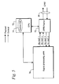
- Fig. 1 shows an example embodiment of a distributed radio base station 20.
- the radio base station 20 comprises both a radio equipment controller (REC) 22 and a radio equipment (RE) 24.
- the radio equipment controller (REC) 22 and radio equipment (RE) 24 are connected by an internal interface 26.
- internal interface 26 is a CPRI link. Details of structure and operation of radio base station 20 and an internal interface 26 which takes the form of a CPRI link are understood from the Common Public Radio Interface Specification Version 1.0 (September 26, 2003) and Version 1.1 (May 10, 2004). As in the specification, the description herein is based on the UMTS (Universal Mobile Telecommunication System) nomenclature. However, the radio base station 20 and the internal interface 26 may operate in accordance with other radio standards.
- UMTS Universal Mobile Telecommunication System
- the radio equipment controller (REC) 22 and radio equipment (RE) 24 may be physically separated (i.e., the radio equipment (RE) 24 may be close to the antenna, whereas the radio equipment controller (REC) 22 may be located in a conveniently accessible site). Alternatively, both radio equipment controller (REC) 22 and radio equipment (RE) 24 may be co-located as in a conventional radio base station design.
- radio equipment controller (REC) 22 provides an access towards an unillustrated Radio Network Controller via the Iub interface 30 (for the UMTS radio access network).
- the radio equipment controller (REC) 22 is concerned with the Iub transport and Iub protocols, the Node B (base station) control and management, as well as the digital baseband processing.
- the radio equipment controller (REC) 22 handles such operations as channel coding, interleaving, spreading, scrambling, adding of physical channels, controlling transmit power of each physical channel, frame and slot signal generation (including clock stabilization).
- the radio equipment controller (REC) 22 handles such operations as channel de-coding, de-interleaving, de-spreading, de-scrambling, signal distribution to signal processing units, detection of feedback information for transmit power control, and signal to interference ratio measurement.
- the radio equipment (RE) 24 serves the air interface 32 to the user equipment (in an UMTS network the air interface is called the Uu interface).
- the user equipment unit, or mobile station, is not illustrated in Fig. 1 .
- the radio equipment (RE) 24 provides the analogue and radio frequency functions such as filtering, modulation, frequency conversion and amplification.
- the radio equipment (RE) 24 performs operations such as digital to analogue conversion, up conversion, on/off control of each carrier, carrier multiplexing, power amplification and limiting, antenna supervision, and RF filtering.
- the radio equipment (RE) 24 performs operations such as analogue to digital conversion, down conversion, automatic gain control, carrier de-multiplexing, low noise amplification, and RF filtering.
- the radio equipment controller (REC) 22 comprises the radio functions of the digital baseband domain, whereas the radio equipment (RE) 24 contains the analogue radio frequency functions.
- the functional split between both parts is done in such a way that a generic interface based on In-Phase and Quadrature (IQ) data can be defined.
- the Common Public Radio Interface Specification Version 1.0 (September 26, 2003) and Version 1.1 (May 10, 2004) define protocols for the physical layer 34 (layer 1) and the data link layer 36 (layer 2).
- Layer 1 defines, e.g., electrical characteristics, optical characteristics, time division multiplexing of the different data flows, and low level signaling.
- Layer 2 defines the media access control, flow control and data protection of the control and management information flow.
- the control plane involves control data flow used for call processing.
- the management plane carries management information for the operation, administration and maintenance of the CPRI link and the radio equipment (RE) 24.
- the control and management data is exchanged between control and management entities with the radio equipment controller (REC) 22 and radio equipment (RE) 24, and is given to higher protocol layers.
- the control and management plane is mapped to a single information flow over the CPRI link.
- the user plane concerns data that has to be transferred from the radio base station to the mobile station and vice versa.
- the user plane data is transported in the form of in-phase and quadrature (IQ) modulation data (digital base band signals), represented by block 40 in Fig. 2 .
- IQ in-phase and quadrature
- Several IQ data flows will be sent via one physical CPRI link 26.
- Each IQ data flow reflects the data of one antenna for one carrier, the so-called antenna-carrier (AxC).
- AxC antenna-carrier
- one antenna-carrier is the amount of digital baseband (IQ) U-plane data necessary for either reception of transmission of one carrier at one independent antenna element.
- An AxC container contains the IQ samples of one AxC for one UMTS chip duration.
- Each flow in the user plane has reserved a certain bit field per frame, denoted as the AxC carrier.
- the AxC container contains samples of a chip an a UTRA-FDD carrier.
- Synchronization pertains to data flow which transfers synchronization and timing information between radio equipment controller (REC) 22 and radio equipment (RE) 24. Synchronization data is used for alignment of the 8B/10B coder as well as the detection of chip, hyperframe, radio frame boundaries, and associated frame numbering.
- Inband signaling depicted by block 42 in Fig. 2 , is signaling information that is related to the link and is directly transported by the physical layer. This information is required, e.g. for system startup, layer 1 link maintenance and the transfer of time critical information that has a direct time relationship to layer 1 user data.
- Block 44 of Fig. 2 shows vendor specific information, i.e., an information flow which is reserved for vendor specific information.
- SAP service access points
- REC radio equipment controller
- RE radio equipment
- SAP CM service access point
- SAP S SAP IQ
- the IQ data of different antenna carriers are multiplexed by a time division multiplexing scheme onto an electrical or optical transmission line forming the internal interface 26.
- the Control and Management data are either sent as inband signalling (for time critical signalling data) or by layer 3 protocols (not defined by Common Public Radio Interface Specification Version 1.0 (September 26, 2003) and Version 1.1 (May 10, 2004)) that reside on top of appropriate layer 2 protocols.
- Layer 3 protocols not defined by Common Public Radio Interface Specification Version 1.0 (September 26, 2003) and Version 1.1 (May 10, 2004)
- Two different layer 2 protocols - High Data Level Link Control (HDLC) and Ethernet, depicted as 46 and 48, respectively, in Fig. 2 - are supported by CPRI.
- HDLC High Data Level Link Control
- Ethernet depicted as 46 and 48, respectively, in Fig. 2 - are supported by CPRI.
- These additional control and management data are time multiplexed with the IQ data.
- additional time slots are available for the transfer of any type of vendor specific information (block 42).
- Fig. 3A illustrates the frame structure for the 614.4Mbit/s total data rate.
- the Common Public Radio Interface Specification Version 1.0 (September 26, 2003) and Version 1.1 (May 10, 2004) also define a hyperframe structure which is hierarchically embedded between the basic frame and the UMTS radio frame as shown in Fig. 3B .
- Z in the hyperframe number X is the basic frame number within a hyperframe
- W is the word number within a basic frame
- Y is the byte number within a word.
- Fig. 4 shows pertinent basic aspects of an example radio equipment (RE) 24 as comprising a framer 50 which is ultimately connected to internal interface 26, i.e., the CPRI interface.
- the framer 50 works in conjunction with a CPU or processor 52 of radio equipment (RE) 24.
- the processor 52 executes control software (SW) 54 which governs operation, e.g., of framer 50 and terminates the application layer communication towards the radio equipment controller (REC) 22.
- radio equipment (RE) 24 comprises plural transmitters (such as transmitter 60 1 and transmitter 60 a ), and plural receivers (such as receiver 62 1 and receiver 62 b ).
- the transmitters 60 and receivers 62 can be either single-standard or multistandard.
- Each transmitter 60 and each receiver 62 is connected to a corresponding antenna 64 (which is distinct from and does not comprise radio equipment (RE) 24).
- the framer 50 is connected to forward payload information obtained from internal interface 26 to each of the transmitters 60 (as shown by lines terminated with solid arrowheads), and to receive information from each of the receivers 62 to be forwarded from radio equipment (RE) 24 over the internal interface 26 to radio equipment controller (REC) 22 (again as indicated by lines terminated with solid arrowheads, but having a reverse direction toward rather than away from framer 50).
- the processor 52 is connected to send control information or control signals to each of framer 50, the transmitters 60, and the receivers 62, as shown by lines terminated with non-solid arrowheads).
- Fig. 5 shows pertinent basic aspects of an example radio equipment controller (REC) 22 as comprising a framer 70 which is ultimately connected to internal interface 26, i.e., the CPRI interface.
- the framer 70 works in conjunction with a CPU or processor 72 of radio equipment controller (REC) 22.
- the processor 72 executes control software (SW) 74 which governs operation, e.g., of framer 70.
- radio equipment controller (REC) 22 comprises signal processing units collectively indicated as 76 in Fig. 5 .
- the radio equipment controller (REC) 22 of Fig. 5 is shown as handling antenna carriers (AxC) AxC 1 and AxC c on the downlink (DL), and antenna carriers (AxC) AxC 1 and AxC d on the uplink (UL).
- the Common Public Radio Interface is time multiplexed with one frame per WCDMA chip period, i.e. a frame rate of 3.84 Mframes/s, with each CPRI frame carrying one or more samples.
- other protocols i.e., protocols other than WCDMA, have other frame or chip rates.
- the present invention facilitates the Common Public Radio Interface (CPRI) accommodating transfer of samples for other protocols.
- the at least one and preferably both of the example radio equipment controller (REC) 22 and the example radio equipment (RE) 24 comprises framers (e.g., framer 50 and framer 70, respectively) which can be controlled for transmitting samples of different protocols over the internal interface 26.
- the framer 50 and framer 70 both facilitate (1) time multiplexing of N number of frames of a first protocol over the internal interface; (2) inserting L number of samples of a second protocol into M number of the frames of the first protocol, and (3) inserting a padding sample into each frame of the first protocol which does not include a sample of the second protocol.
- the first protocol has a frame rate; the second protocol has a sample rate, and N is greater than L and M, with L, M, and N all being integers.
- CPRI Common Public Radio Interface
- the frame rate of the first protocol is 3.84 Mframes/second.
- the CPRI has a frame rate which happens to be the same as the WCDMA chip rate. It should be understood that the principles of the present invention are not confined to the Common Public Radio Interface (CPRI), but are applicable to any internal interface 26 of a distributed base station.
- Fig. 7 illustrates a first example mode of transmitting samples of a different protocol over the internal interface 26.
- the second protocol is CDMA 2000, for which the chip rate (i.e., sample rate) is 3.6864 Mchips/second.
- N is 25 and L and M are 24.
- twenty four CDMA 2000 samples 80 1 are inserted in twenty four CPRI frames, one sample 80 1 per chip (i.e. per frame), as indicated by the frames of Fig. 7 which have solid internal squares depicting samples 80 1 .
- the last CPRI frame (chip) does not contain a CDMA 2000 sample 80 1 but instead is a padding frame which carries a padding sample. That is, in the last CPRI frame the corresponding AxC container contains padding.
- CDMA 2000 carrier can be transferred over the interface at the same time as WCDMA carriers are transferred, rendering internal interface 26 a multistandard interface.
- the padding sample can comprise either of uninterpreted information or information related to the second protocol.
- the padding sample can comprise a parity value for the L number of samples of the second protocol.
- Fig. 8 illustrates a second example mode of transmitting samples 80 2 of a different protocol over the internal interface 26.
- the second protocol is CDMA One (e.g., IS-95), for which the chip rate (i.e., sample rate) is 1.2288 Mchips/second.
- N is 25 and L is 8.
- eight CDMA One samples 80 2 are inserted in eight CPRI frames, one sample 80 2 per chip (i.e. per frame) of the eight involved CPRI frames, as indicated by the frames of Fig. 8 which have solid internal squares depicting samples 80 2 .
- this second mode and as shown in Fig.
- M is 8, with the frames of the first protocol which host the second protocol samples being the first, fourth, seventh, tenth, thirteenth, sixteenth, nineteenth, and twenty second first protocol frames.
- the AxC containers for seventeen of the first protocol frames contain padding.
- CDMA One e.g., IS-95
- CDMA 2000 1x which uses the same chip rate (e.g., sample rate) as CDMA One.
- Fig. 9 illustrates a third example mode of transmitting samples 80 3-1, 80 3-2 , and 80 3-3 of a different protocol over the internal interface 26.
- the second protocol is CDMA One (e.g., IS-95), for which the chip rate (i.e., sample rate) is 1.2288 Mchips/second.
- the framer 50 and framer 70 use the second protocol for K number of carriers. Specifically, samples for each of K number of carriers of the second protocol are included in M/K number of frames of the first protocol.
- Fig. 9 illustrates a first carrier of the second protocol as having eight samples 80 3-1 (in first protocol frames 1, 4, 7, 10, 13, 16, 19, and 22); a second carrier of the second protocol as having eight samples 80 3-2 (in first protocol frames 2, 5, 8, 11, 14, 17, 20, and 23); and, a third carrier of the second protocol as having eight samples 80 3-3 (in first protocol frames 3, 6, 9, 12, 15, 18, 21, and 24); followed by a padding sample in the last first protocol frame.
- This third example mode thus illustrates an example of interleaving of second protocol carriers over the internal interface 26.
- the three second protocol carriers are fitted in the same space as one carrier for the first protocol (e.g., for WCDMA).
- Fig. 10 illustrates a fourth example mode of transmitting samples 80 4 of a different protocol over the internal interface 26.
- the second protocol is CDMA One (e.g., IS-95), for which the chip rate (i.e., sample rate) is 1.2288 Mchips/second.
- the framer 50 and the framer 70 include J number of bits of each second protocol sample in F number of frames of the first protocol, J and F being integers.
- N is 25, L is 8; J is 14, and F is 3.
- the technique of the fourth mode is to subdivide each sample 80 4 into about F number (e.g., 3) parts and to transfer the about 1/F (e.g., 1/3) of the sample in each first protocol (CPRI) basic frame.
- the adoption to the CPRI rate is done by adding some padding bits.
- An implementation of the fourth mode is to map the J number of bits of each second protocol sample into F number of first protocol frames, wherein the AxC container size would be at least J/F rounded up to the nearest even integer (so that the AxC container always has an even length).
- the AxC container of the last first protocol frame would then not carry any information.
- each second protocol sample 80 4 can be split into three AxC containers each having a length of six bits. These three AxC containers are preferably inserted into three consecutive first protocol frames, with a first of the six bits of the second protocol sample 80 4 being included in a first of the first protocol frames (e.g., first protocol frame 82 1 ), the next six bits of the second protocol sample 80 4 being included in a second of the first protocol frames (e.g., first protocol frame 82 2 ), and the last two bits of the second protocol sample 80 4 being included in a third of the first protocol frames (e.g., first protocol frame 82 3 ).
- the apparatus and methods herein describe makes possible use of an internal interface 26 such as the CPRI for other protocols, such as for CDMA2000, thereby rendering internal interface 26 for multistandard usage.
- Interleaving techniques such as that described in the third example modes, allows for yet other standards to also be transferred over the interface, such as GSM and CDMA One.
- all example modes and solutions involve minimized queuing.
- FIG. 6 Selected aspects of the framer 50 of radio equipment (RE) 24 and the framer 70 of radio equipment controller (REC) 22 which facilitate transmission of samples of different protocols over the internal interface 26 are illustrated in Fig. 6 .
- Each of framer 50 and framer 70 are shown as operating in conjunction with an internal interface in-buffer 84 (e.g., CPRI in-buffer); an internal interface out-buffer 86; and, a basic frame counter 88.
- the framer is shown has having, for each antenna carrier (AxC), logic 90 for handling different protocols or modes.
- the framer handles only one block as being active at a time the block being selected by the control software (SW).
- the radio equipment controller (REC) 22 decides what standard the radio equipment (RE) 24 shall transmit and receive, i.e., which protocol standard shall be utilized over the internal interface 26.
- the radio equipment controller (REC) 22 then sends a command to the radio equipment (RE) 24 to start transmitting a carrier and/to start receiving a carrier.
- the command includes an indication of what frequency it to be used for transmission and receipt, and which standard to use.
- radio equipment controller (REC) 22 and radio equipment (RE) 24 may be performed at radio equipment controller (REC) 22 and radio equipment (RE) 24 depending on the particular protocol standard which has been chosen by radio equipment controller (REC) 22 (such as, for example, pulse shaping filtering). Concerning encoding and extracting, the radio equipment controller (REC) 22 samples the RF signal and does the proper filtering, and then simply maps the samples according to the selected scheme. The radio equipment (RE) 24 extracts the samples according to the selected schemes and then treats them as any other samples from that standard. For each protocol standard there is a flow of samples at a known rate. This flow is encoded over the internal interface 26 in a way that gives minimum extra delay and minimum complexity.
- the control software (SW) 54 executed by processor 52 configures each of the transmitters 60, the receivers 62, and the framer 50 in accordance with the standard and specific CPRI format specified in commands received over internal interface 26 from radio equipment controller (REC) 22.
- the control software (SW) 74 executed by processor 72 configures the signal processing units 76 and framer 70 in accordance with the standard and specific CPRI format to use for each antenna carrier, based on the desired configuration at the moment.
- the framer 70 converts between the CPRI format and the format suitable for the transmitter/receiver based on the selected standard for each antenna carrier.
- data can be transferred between radio equipment controller (REC) 22 and radio equipment (RE) 24 by summing the different carriers in the radio equipment controller (REC) 22 and transferring a wide band signal over the internal interface 26. For example, if there are six GSM carriers over a 5 MHz spectrum, the 5 MHz spectrum can be generated in the radio equipment controller (REC) 22 and transferred as a single flow of samples over the internal interface 26.
- the transmitter 60 11 and receiver 62 11 are of a wideband character (e.g., can transmit or receive more than one channel), and transmitter 60 11 is a multi-carrier transmitter.
- the narrow band carriers are digitally up-converted in radio equipment controller (REC) 22 by digital upconverter and summer 92, and digitally down-converted in radio equipment controller (REC) 22 by digital downconverter and summer 93.
- Fig. 11 shows a generic embodiment with separate functional blocks converting between an arbitrary band width and a band width based on 3.84 MHz.
- These blocks are denoted resamplers as their basic task is to change the sample rate between the incoming and outgoing signals by means of signal processing, and are present on both uplink (95,97) and downlink (91, 96).
- the functional blocks can be removed as separate blocks by basing the upconverter 92, downconverter 93, transmitter 60 and receiver 62 on a multiple of 3.84 MHz.
- the corresponding AxC container on the interface 26 is therefore of size 3*sample size.
- the corresponding inversive function is performed by a resampler 96 which converts the signal back to the original sample rate of the 5 MHz base band signal.
- the resampling is performed in resampler 97 in the RE, transferred over the interface 26 and then resampled again in the REC by resampler 95.
- the D/A converter of transmitter 60 and the A/D converter of the receiver 62 should work on 11.52 MHz and the digital upconverter 92 and downconverter 93 should also work on 11.52 MHz. Resamplers 91, 95, 96 and 97 would then be obsolete.
- Fig. 12 shows an example distributed radio base station 20 12 which has a cascading of radio equipments.
- the radio equipment controller (REC) 22 12 is connected by internal interface 26 to a first radio equipment (RE) 24 12-1 .
- the first radio equipment (RE) 24 12 -1 utilizes a first protocol such as WCDMA.
- the first radio equipment (RE) 24 12 -1 is connected by a link 99 to second radio equipment (RE) 24 12 -2.
- the second radio equipment (RE) 24 12 -2 utilizes a second protocol such as CDMA 2000.
- the same internal interface 26 is used to transfer CDMA 2000 antenna-carriers to second radio equipment (RE) 24 12 -2 and to transfer WCDMA antenna-carriers to first radio equipment (RE) 24 12 -1.
- the invention has been described in a basic configuration in which one radio equipment controller (REC) 22 and one radio equipment (RE) 24 are connected by a single CPRI physical link.
- the invention is not limited to this configuration, but should be understood to be extended to other configurations including but not limited to those described in Common Public Radio Interface Specification Version 1.0 (September 26, 2003) and Version 1.1 (May 10, 2004).
- Fig. 13A the invention may be implemented in a configuration in which several CPRI physical links can be used to enhance the system capacity required for large system configurations involving many antennas and carriers.
- Fig. 13B several radio equipment entities may be served by one radio equipment controller (REC) 22.
Landscapes
- Engineering & Computer Science (AREA)
- Computer Networks & Wireless Communication (AREA)
- Signal Processing (AREA)
- Mobile Radio Communication Systems (AREA)
Claims (14)
- Procédé de fonctionnement d'une station de base radio (20) ayant une interface interne (26) connectant un équipement radio (22) et un contrôleur (24) d'équipement radio, le procédé étant caractérisé par le fait de :multiplexer dans le temps un nombre N de trames d'un premier protocole sur l'interface interne (26), le premier protocole ayant un taux de trames ;insérer un nombre L d'échantillons d'un deuxième protocole dans un nombre M des trames du premier protocole, le deuxième protocole ayant un taux d'échantillonnage qui est différent du taux de trames du premier protocole, N étant supérieur à L et M, où L, M, et N sont des nombres entiers :insérer un échantillon de remplissage dans chaque trame du premier protocole qui n'inclut pas un échantillon du deuxième protocole.
- Procédé de la revendication 1, dans lequel l'interface interne (26) est une Interface Radio Publique Commune (CPRI), où le taux de trames du premier protocole est de 3, 84 Mtrames/seconde ; où le taux d'échantillonnage du deuxième protocole est de 3,6864 Mpuces/seconde ; où N est égal à 25 ; et où L et M sont égaux à 24.
- Procédé de la revendication 1, dans lequel l'interface interne (26) est une Interface Radio Publique Commune (CPRI), où le taux de trames du premier protocole est de 3,84 Mtrames/seconde ; et où le taux d'échantillonnage du deuxième protocole est de 1,2288 Mpuces/seconde.
- Procédé de la revendication 1, dans lequel l'interface interne (26) est une Interface Radio Publique Commune (CPRI), où le taux de trames du premier protocole est de 3, 84 Mtrames/seconde ; où le taux d'échantillonnage du deuxième protocole est de 1,2288 Mpuces/seconde ; et comprenant en outre l'utilisation du deuxième protocole pour un nombre K de supports moyennant quoi des échantillons pour chaque support du deuxième protocole sont inclus dans un nombre M/K de trames du premier protocole.
- Procédé de la revendication 1, dans lequel l'interface interne (26) est une Interface Radio Publique Commune (CPRI), où le taux de trames du premier protocole est de 3,84 Mtrames/seconde ; où le taux d'échantillonnage du deuxième protocole est de 1,2288 Mpuces/seconde ; où chaque échantillon du deuxième protocole a un nombre J de bits ; et
dans lequel le procédé comprend en outre le fait d'inclure le nombre J de bits de chaque échantillon du deuxième protocole dans un nombre F de trames du premier protocole. J et F étant des nombres entiers. - Procédé de la revendication 1, dans lequel l'échantillon de remplissage comprend l'une de l'information non interprétée et de l'information relative au deuxième protocole.
- Procédé de la revendication 1, dans lequel l'échantillon de remplissage comprend une valeur de parité pour le nombre L d'échantillons du deuxième protocole.
- Station de base radio (20) ayant une interface interne (26) connectant un équipement radio (22) et un contrôleur (24) d'équipement radio, caractérisée en ce qu'au moins l'un de l'équipement radio (22) et du contrôleur (24) d'équipement radio comprend un trameur qui est configuré pour (1) multiplexer dans le temps un nombre N de trames d'un premier protocole sur l'interface interne (26), le premier protocole ayant un taux de trames ; (2) insérer un nombre L d'échantillons d'un deuxième protocole dans un nombre M des trames du premier protocole, le deuxième protocole ayant un taux d'échantillonnage qui est différent du taux de trames du premier protocole, N étant supérieur à L et M, où L, M et N sont des nombres entiers ; et (3) insérer un échantillon de remplissage dans chaque trame du premier protocole qui n'inclut pas un échantillon du deuxième protocole.
- Station de base radio de la revendication 8, dans laquelle l'interface interne (26) est une Interface Radio Publique Commune (CPRI), où le taux de trames du premier protocole est de 3,84 Mtrames/seconde ; où le taux d'échantillonnage du deuxième protocole est de 3,6864 Mpuces/seconde ; où N est égal à 25 ; et où L et M sont égaux à 24.
- Station de base radio de la revendication 8, dans laquelle l'interface interne (26) est une Interface Radio Publique Commune (CPRI), où le taux de trames du premier protocole est de 3,84 Mtrames/seconde ; et où le taux d'échantillonnage du deuxième protocole est de 1,2288 Mpuces/seconde.
- Station de base radio de la revendication 8, dans laquelle l'interface interne (26) est une Interface Radio Publique Commune (CPRI), où le taux de trames du premier protocole est de 3,84 Mtrames/seconde ; où le taux d'échantillonnage du deuxième protocole est de 1,2288 Mpuces/seconde, et où le trameur utilise le deuxième protocole pour un nombre K de supports moyennant quoi des échantillons pour chaque support du deuxième protocole sont inclus dans un nombre M/K de trames du premier protocole.
- Station de base radio de la revendication 8, dans laquelle l'interface interne (26) est une Interface Radio Publique Commune (CPRI), où le taux de trames du premier protocole est de 3,84 Mtrames/seconde ; où le taux d'échantillonnage du deuxième protocole est de 1,2288 Mpuces/seconde ; où chaque échantillon du deuxième protocole a un nombre J de bits ; et où le trameur comporte le nombre J de bits de chaque échantillon du deuxième protocole dans un nombre F de trames du premier protocole, J et F étant des nombres entiers.
- Station de base radio de la revendication 8, dans laquelle l'échantillon de remplissage comprend l'une de l'information non interprétée et de l'information relative au deuxième protocole.
- Station de base radio de la revendication 8, dans laquelle l'échantillon de remplissage comprend une valeur de parité pour le nombre L d'échantillons du deuxième protocole.
Priority Applications (1)
| Application Number | Priority Date | Filing Date | Title |
|---|---|---|---|
| EP11189157.8A EP2421329A3 (fr) | 2003-11-17 | 2004-11-16 | Encapsulation de divers protocoles sur une interface interne de station de base radio distribuée |
Applications Claiming Priority (3)
| Application Number | Priority Date | Filing Date | Title |
|---|---|---|---|
| US52032303P | 2003-11-17 | 2003-11-17 | |
| US10/909,835 US7460513B2 (en) | 2003-11-17 | 2004-08-03 | Encapsulation of diverse protocols over internal interface of distributed radio base station |
| PCT/SE2004/001675 WO2005048625A1 (fr) | 2003-11-17 | 2004-11-16 | Integration de divers protocoles sur une interface internet d'une station radio de base repartie |
Related Child Applications (2)
| Application Number | Title | Priority Date | Filing Date |
|---|---|---|---|
| EP11189157.8A Division EP2421329A3 (fr) | 2003-11-17 | 2004-11-16 | Encapsulation de divers protocoles sur une interface interne de station de base radio distribuée |
| EP11189157.8 Division-Into | 2011-11-15 |
Publications (2)
| Publication Number | Publication Date |
|---|---|
| EP1688002A1 EP1688002A1 (fr) | 2006-08-09 |
| EP1688002B1 true EP1688002B1 (fr) | 2013-07-31 |
Family
ID=34594991
Family Applications (2)
| Application Number | Title | Priority Date | Filing Date |
|---|---|---|---|
| EP11189157.8A Withdrawn EP2421329A3 (fr) | 2003-11-17 | 2004-11-16 | Encapsulation de divers protocoles sur une interface interne de station de base radio distribuée |
| EP04800338.8A Not-in-force EP1688002B1 (fr) | 2003-11-17 | 2004-11-16 | Integration de divers protocoles sur une interface interne d'une station radio de base repartie |
Family Applications Before (1)
| Application Number | Title | Priority Date | Filing Date |
|---|---|---|---|
| EP11189157.8A Withdrawn EP2421329A3 (fr) | 2003-11-17 | 2004-11-16 | Encapsulation de divers protocoles sur une interface interne de station de base radio distribuée |
Country Status (5)
| Country | Link |
|---|---|
| EP (2) | EP2421329A3 (fr) |
| CN (1) | CN100477864C (fr) |
| ES (1) | ES2430548T3 (fr) |
| HK (1) | HK1099461A1 (fr) |
| WO (1) | WO2005048625A1 (fr) |
Families Citing this family (25)
| Publication number | Priority date | Publication date | Assignee | Title |
|---|---|---|---|---|
| EP1744572A1 (fr) * | 2005-07-13 | 2007-01-17 | Siemens Aktiengesellschaft | Transfert de paquets Ethernet sur une interface CPRI |
| EP1858276B8 (fr) | 2006-05-15 | 2018-05-02 | Nokia Solutions and Networks GmbH & Co. KG | Interface pour la transmission efficace de signaux numériques |
| JP4814992B2 (ja) * | 2007-03-16 | 2011-11-16 | 富士通株式会社 | 基地局、無線制御装置、無線装置およびデータ転送方法 |
| WO2008120297A1 (fr) | 2007-03-28 | 2008-10-09 | Fujitsu Limited | Procédé pour une communication de données entre un équipement de commande radio et un équipement radio, équipement de commande radio et équipement radio |
| EP2232942B1 (fr) * | 2008-01-17 | 2018-05-02 | Telefonaktiebolaget LM Ericsson (publ) | Communication asynchrone sur une interface radio publique commune (cpri) |
| CN101499964B (zh) * | 2008-01-28 | 2011-06-15 | 华为技术有限公司 | 提高cpri接口传输带宽利用率的方法、cpri接口处理模块和设备 |
| US8458558B2 (en) | 2008-04-30 | 2013-06-04 | Motorola Mobility Llc | Multi-antenna configuration signaling in wireless communication system |
| US8005152B2 (en) | 2008-05-21 | 2011-08-23 | Samplify Systems, Inc. | Compression of baseband signals in base transceiver systems |
| US8144712B2 (en) | 2008-08-07 | 2012-03-27 | Motorola Mobility, Inc. | Scheduling grant information signaling in wireless communication system |
| CN101394197B (zh) * | 2008-09-28 | 2012-07-18 | 中兴通讯股份有限公司 | 一种cdma分布式基站系统的基带数据传输方法及其设备 |
| CN101707499B (zh) * | 2009-10-29 | 2014-08-20 | 中兴通讯股份有限公司 | 实现cdma与wcdma兼容的数据传输方法及系统 |
| CN102118795B (zh) | 2009-12-31 | 2013-10-09 | 华为技术有限公司 | 无线基站中公共通用无线接口数据的传送方法及无线基站 |
| US20110223958A1 (en) | 2010-03-10 | 2011-09-15 | Fujitsu Limited | System and Method for Implementing Power Distribution |
| US8649388B2 (en) | 2010-09-02 | 2014-02-11 | Integrated Device Technology, Inc. | Transmission of multiprotocol data in a distributed antenna system |
| US8989088B2 (en) | 2011-01-07 | 2015-03-24 | Integrated Device Technology Inc. | OFDM signal processing in a base transceiver system |
| US9059778B2 (en) | 2011-01-07 | 2015-06-16 | Integrated Device Technology Inc. | Frequency domain compression in a base transceiver system |
| US9634863B2 (en) | 2011-11-11 | 2017-04-25 | Kollmorgen Corporation | Systems and methods for supporting two different protocols on a same physical connection |
| US9215296B1 (en) | 2012-05-03 | 2015-12-15 | Integrated Device Technology, Inc. | Method and apparatus for efficient radio unit processing in a communication system |
| US9203933B1 (en) | 2013-08-28 | 2015-12-01 | Integrated Device Technology, Inc. | Method and apparatus for efficient data compression in a communication system |
| US9485688B1 (en) | 2013-10-09 | 2016-11-01 | Integrated Device Technology, Inc. | Method and apparatus for controlling error and identifying bursts in a data compression system |
| US9398489B1 (en) | 2013-10-09 | 2016-07-19 | Integrated Device Technology | Method and apparatus for context based data compression in a communication system |
| US8989257B1 (en) | 2013-10-09 | 2015-03-24 | Integrated Device Technology Inc. | Method and apparatus for providing near-zero jitter real-time compression in a communication system |
| US9313300B2 (en) | 2013-11-07 | 2016-04-12 | Integrated Device Technology, Inc. | Methods and apparatuses for a unified compression framework of baseband signals |
| EP2887758A1 (fr) * | 2013-12-20 | 2015-06-24 | Nokia Solutions and Networks Oy | Détermination de protocole de station de base |
| EP3381219B1 (fr) * | 2015-11-24 | 2020-09-09 | Telefonaktiebolaget LM Ericsson (PUBL) | Commutation de signaux de données d'au moins deux types, pour une transmission sur un réseau de transport fournissant à la fois une connectivité backhaul et une connectivité fronthaul (xhaul) |
Family Cites Families (7)
| Publication number | Priority date | Publication date | Assignee | Title |
|---|---|---|---|---|
| SE516182C2 (sv) * | 1999-02-26 | 2001-11-26 | Ericsson Telefon Ab L M | Mottagning av olika signalformatstandarder i radiosystem med flera standarder |
| US6411653B1 (en) * | 1999-07-16 | 2002-06-25 | Lucent Technologies Inc. | Cascaded polyphase DFT-filter band for a wireless telecommunications system |
| US6429974B1 (en) * | 2000-05-12 | 2002-08-06 | Mahi Networks | Add-drop multiplexer |
| US7158591B2 (en) * | 2001-05-09 | 2007-01-02 | Signum Concept, Inc. | Recursive resampling digital filter structure for demodulating 3G wireless signals |
| US20030093540A1 (en) * | 2001-11-14 | 2003-05-15 | Marcello Lioy | Proxy network layer protocol support in a wireless communication network |
| SE523400C2 (sv) * | 2001-11-30 | 2004-04-13 | Ericsson Telefon Ab L M | Cellulärt radiokommunikationssystem som utnyttjar trådlösa optiska länkar samt förfarande för drift av systemet |
| GB2405061B (en) * | 2001-12-05 | 2005-05-18 | Matsushita Electric Ind Co Ltd | Multirate digital transceiver |
-
2004
- 2004-11-16 CN CN 200480033918 patent/CN100477864C/zh not_active Expired - Fee Related
- 2004-11-16 WO PCT/SE2004/001675 patent/WO2005048625A1/fr not_active Application Discontinuation
- 2004-11-16 EP EP11189157.8A patent/EP2421329A3/fr not_active Withdrawn
- 2004-11-16 ES ES04800338T patent/ES2430548T3/es active Active
- 2004-11-16 EP EP04800338.8A patent/EP1688002B1/fr not_active Not-in-force
-
2007
- 2007-06-15 HK HK07106480.7A patent/HK1099461A1/xx not_active IP Right Cessation
Also Published As
| Publication number | Publication date |
|---|---|
| CN1883217A (zh) | 2006-12-20 |
| HK1099461A1 (en) | 2007-08-10 |
| CN100477864C (zh) | 2009-04-08 |
| EP1688002A1 (fr) | 2006-08-09 |
| WO2005048625A1 (fr) | 2005-05-26 |
| EP2421329A2 (fr) | 2012-02-22 |
| EP2421329A3 (fr) | 2016-07-13 |
| ES2430548T3 (es) | 2013-11-21 |
Similar Documents
| Publication | Publication Date | Title |
|---|---|---|
| US7460513B2 (en) | Encapsulation of diverse protocols over internal interface of distributed radio base station | |
| EP1688002B1 (fr) | Integration de divers protocoles sur une interface interne d'une station radio de base repartie | |
| EP2421330B1 (fr) | Encapsulation de transmissions indépendantes sur une interface interne de station de base radio distribuée | |
| KR101101542B1 (ko) | 무선 기지국에서 무선 장비 제어 노드와 원격 무선 장비노드 간에 통신하기 위한 인터페이스, 장치 및 방법 | |
| US6370185B1 (en) | Translating repeater system with improved backhaul efficiency | |
| EP1810534B1 (fr) | Communication entre un noeud de commande d'equipement radio et plusieurs noeuds d'equipement radio a distance | |
| US6567389B1 (en) | Method and arrangement for high-speed data transmission in a mobile telecommunications system | |
| US20050107124A1 (en) | Pre-start-up procedure for internal interface of distributed radio base station | |
| EP2232942B1 (fr) | Communication asynchrone sur une interface radio publique commune (cpri) | |
| US20140079037A1 (en) | Transmission of multiprotocol data in a distributed antenna system | |
| EP1685691B1 (fr) | Procedure de pre-demarrage pour l'interface interne d'une station fixe radio distribuee |
Legal Events
| Date | Code | Title | Description |
|---|---|---|---|
| PUAI | Public reference made under article 153(3) epc to a published international application that has entered the european phase |
Free format text: ORIGINAL CODE: 0009012 |
|
| 17P | Request for examination filed |
Effective date: 20060619 |
|
| AK | Designated contracting states |
Kind code of ref document: A1 Designated state(s): AT BE BG CH CY CZ DE DK EE ES FI FR GB GR HU IE IS IT LI LU MC NL PL PT RO SE SI SK TR |
|
| DAX | Request for extension of the european patent (deleted) | ||
| 17Q | First examination report despatched |
Effective date: 20091106 |
|
| REG | Reference to a national code |
Ref country code: DE Ref legal event code: R079 Ref document number: 602004042931 Country of ref document: DE Free format text: PREVIOUS MAIN CLASS: H04Q0007300000 Ipc: H04W0088080000 |
|
| RIC1 | Information provided on ipc code assigned before grant |
Ipc: H04W 88/08 20090101AFI20130109BHEP |
|
| GRAP | Despatch of communication of intention to grant a patent |
Free format text: ORIGINAL CODE: EPIDOSNIGR1 |
|
| RAP1 | Party data changed (applicant data changed or rights of an application transferred) |
Owner name: TELEFONAKTIEBOLAGET LM ERICSSON (PUBL) |
|
| GRAS | Grant fee paid |
Free format text: ORIGINAL CODE: EPIDOSNIGR3 |
|
| GRAA | (expected) grant |
Free format text: ORIGINAL CODE: 0009210 |
|
| RAP1 | Party data changed (applicant data changed or rights of an application transferred) |
Owner name: TELEFONAKTIEBOLAGET L M ERICSSON (PUBL) |
|
| AK | Designated contracting states |
Kind code of ref document: B1 Designated state(s): AT BE BG CH CY CZ DE DK EE ES FI FR GB GR HU IE IS IT LI LU MC NL PL PT RO SE SI SK TR |
|
| REG | Reference to a national code |
Ref country code: GB Ref legal event code: FG4D Ref country code: CH Ref legal event code: EP |
|
| REG | Reference to a national code |
Ref country code: AT Ref legal event code: REF Ref document number: 625272 Country of ref document: AT Kind code of ref document: T Effective date: 20130815 |
|
| REG | Reference to a national code |
Ref country code: IE Ref legal event code: FG4D |
|
| REG | Reference to a national code |
Ref country code: DE Ref legal event code: R096 Ref document number: 602004042931 Country of ref document: DE Effective date: 20130926 |
|
| REG | Reference to a national code |
Ref country code: NL Ref legal event code: T3 |
|
| REG | Reference to a national code |
Ref country code: ES Ref legal event code: FG2A Ref document number: 2430548 Country of ref document: ES Kind code of ref document: T3 Effective date: 20131121 |
|
| REG | Reference to a national code |
Ref country code: AT Ref legal event code: MK05 Ref document number: 625272 Country of ref document: AT Kind code of ref document: T Effective date: 20130731 |
|
| PG25 | Lapsed in a contracting state [announced via postgrant information from national office to epo] |
Ref country code: CY Free format text: LAPSE BECAUSE OF FAILURE TO SUBMIT A TRANSLATION OF THE DESCRIPTION OR TO PAY THE FEE WITHIN THE PRESCRIBED TIME-LIMIT Effective date: 20130710 Ref country code: AT Free format text: LAPSE BECAUSE OF FAILURE TO SUBMIT A TRANSLATION OF THE DESCRIPTION OR TO PAY THE FEE WITHIN THE PRESCRIBED TIME-LIMIT Effective date: 20130731 Ref country code: BE Free format text: LAPSE BECAUSE OF FAILURE TO SUBMIT A TRANSLATION OF THE DESCRIPTION OR TO PAY THE FEE WITHIN THE PRESCRIBED TIME-LIMIT Effective date: 20130731 Ref country code: IS Free format text: LAPSE BECAUSE OF FAILURE TO SUBMIT A TRANSLATION OF THE DESCRIPTION OR TO PAY THE FEE WITHIN THE PRESCRIBED TIME-LIMIT Effective date: 20131130 Ref country code: PT Free format text: LAPSE BECAUSE OF FAILURE TO SUBMIT A TRANSLATION OF THE DESCRIPTION OR TO PAY THE FEE WITHIN THE PRESCRIBED TIME-LIMIT Effective date: 20131202 Ref country code: SE Free format text: LAPSE BECAUSE OF FAILURE TO SUBMIT A TRANSLATION OF THE DESCRIPTION OR TO PAY THE FEE WITHIN THE PRESCRIBED TIME-LIMIT Effective date: 20130731 |
|
| PG25 | Lapsed in a contracting state [announced via postgrant information from national office to epo] |
Ref country code: GR Free format text: LAPSE BECAUSE OF FAILURE TO SUBMIT A TRANSLATION OF THE DESCRIPTION OR TO PAY THE FEE WITHIN THE PRESCRIBED TIME-LIMIT Effective date: 20131101 Ref country code: FI Free format text: LAPSE BECAUSE OF FAILURE TO SUBMIT A TRANSLATION OF THE DESCRIPTION OR TO PAY THE FEE WITHIN THE PRESCRIBED TIME-LIMIT Effective date: 20130731 Ref country code: PL Free format text: LAPSE BECAUSE OF FAILURE TO SUBMIT A TRANSLATION OF THE DESCRIPTION OR TO PAY THE FEE WITHIN THE PRESCRIBED TIME-LIMIT Effective date: 20130731 Ref country code: SI Free format text: LAPSE BECAUSE OF FAILURE TO SUBMIT A TRANSLATION OF THE DESCRIPTION OR TO PAY THE FEE WITHIN THE PRESCRIBED TIME-LIMIT Effective date: 20130731 |
|
| PG25 | Lapsed in a contracting state [announced via postgrant information from national office to epo] |
Ref country code: CY Free format text: LAPSE BECAUSE OF FAILURE TO SUBMIT A TRANSLATION OF THE DESCRIPTION OR TO PAY THE FEE WITHIN THE PRESCRIBED TIME-LIMIT Effective date: 20130731 |
|
| PG25 | Lapsed in a contracting state [announced via postgrant information from national office to epo] |
Ref country code: SK Free format text: LAPSE BECAUSE OF FAILURE TO SUBMIT A TRANSLATION OF THE DESCRIPTION OR TO PAY THE FEE WITHIN THE PRESCRIBED TIME-LIMIT Effective date: 20130731 Ref country code: RO Free format text: LAPSE BECAUSE OF FAILURE TO SUBMIT A TRANSLATION OF THE DESCRIPTION OR TO PAY THE FEE WITHIN THE PRESCRIBED TIME-LIMIT Effective date: 20130731 Ref country code: DK Free format text: LAPSE BECAUSE OF FAILURE TO SUBMIT A TRANSLATION OF THE DESCRIPTION OR TO PAY THE FEE WITHIN THE PRESCRIBED TIME-LIMIT Effective date: 20130731 Ref country code: EE Free format text: LAPSE BECAUSE OF FAILURE TO SUBMIT A TRANSLATION OF THE DESCRIPTION OR TO PAY THE FEE WITHIN THE PRESCRIBED TIME-LIMIT Effective date: 20130731 Ref country code: CZ Free format text: LAPSE BECAUSE OF FAILURE TO SUBMIT A TRANSLATION OF THE DESCRIPTION OR TO PAY THE FEE WITHIN THE PRESCRIBED TIME-LIMIT Effective date: 20130731 |
|
| PG25 | Lapsed in a contracting state [announced via postgrant information from national office to epo] |
Ref country code: IT Free format text: LAPSE BECAUSE OF FAILURE TO SUBMIT A TRANSLATION OF THE DESCRIPTION OR TO PAY THE FEE WITHIN THE PRESCRIBED TIME-LIMIT Effective date: 20130731 |
|
| PLBE | No opposition filed within time limit |
Free format text: ORIGINAL CODE: 0009261 |
|
| STAA | Information on the status of an ep patent application or granted ep patent |
Free format text: STATUS: NO OPPOSITION FILED WITHIN TIME LIMIT |
|
| REG | Reference to a national code |
Ref country code: CH Ref legal event code: PL |
|
| 26N | No opposition filed |
Effective date: 20140502 |
|
| PG25 | Lapsed in a contracting state [announced via postgrant information from national office to epo] |
Ref country code: MC Free format text: LAPSE BECAUSE OF FAILURE TO SUBMIT A TRANSLATION OF THE DESCRIPTION OR TO PAY THE FEE WITHIN THE PRESCRIBED TIME-LIMIT Effective date: 20130731 Ref country code: LI Free format text: LAPSE BECAUSE OF NON-PAYMENT OF DUE FEES Effective date: 20131130 Ref country code: CH Free format text: LAPSE BECAUSE OF NON-PAYMENT OF DUE FEES Effective date: 20131130 |
|
| REG | Reference to a national code |
Ref country code: DE Ref legal event code: R097 Ref document number: 602004042931 Country of ref document: DE Effective date: 20140502 |
|
| REG | Reference to a national code |
Ref country code: FR Ref legal event code: ST Effective date: 20140731 |
|
| REG | Reference to a national code |
Ref country code: IE Ref legal event code: MM4A |
|
| PG25 | Lapsed in a contracting state [announced via postgrant information from national office to epo] |
Ref country code: IE Free format text: LAPSE BECAUSE OF NON-PAYMENT OF DUE FEES Effective date: 20131116 |
|
| PG25 | Lapsed in a contracting state [announced via postgrant information from national office to epo] |
Ref country code: FR Free format text: LAPSE BECAUSE OF NON-PAYMENT OF DUE FEES Effective date: 20131202 |
|
| PG25 | Lapsed in a contracting state [announced via postgrant information from national office to epo] |
Ref country code: TR Free format text: LAPSE BECAUSE OF FAILURE TO SUBMIT A TRANSLATION OF THE DESCRIPTION OR TO PAY THE FEE WITHIN THE PRESCRIBED TIME-LIMIT Effective date: 20130731 |
|
| PG25 | Lapsed in a contracting state [announced via postgrant information from national office to epo] |
Ref country code: HU Free format text: LAPSE BECAUSE OF FAILURE TO SUBMIT A TRANSLATION OF THE DESCRIPTION OR TO PAY THE FEE WITHIN THE PRESCRIBED TIME-LIMIT; INVALID AB INITIO Effective date: 20041116 Ref country code: BG Free format text: LAPSE BECAUSE OF FAILURE TO SUBMIT A TRANSLATION OF THE DESCRIPTION OR TO PAY THE FEE WITHIN THE PRESCRIBED TIME-LIMIT Effective date: 20130731 Ref country code: LU Free format text: LAPSE BECAUSE OF NON-PAYMENT OF DUE FEES Effective date: 20131116 |
|
| PGFP | Annual fee paid to national office [announced via postgrant information from national office to epo] |
Ref country code: NL Payment date: 20181126 Year of fee payment: 15 |
|
| PGFP | Annual fee paid to national office [announced via postgrant information from national office to epo] |
Ref country code: DE Payment date: 20181128 Year of fee payment: 15 |
|
| PGFP | Annual fee paid to national office [announced via postgrant information from national office to epo] |
Ref country code: GB Payment date: 20181127 Year of fee payment: 15 Ref country code: ES Payment date: 20181203 Year of fee payment: 15 |
|
| REG | Reference to a national code |
Ref country code: DE Ref legal event code: R119 Ref document number: 602004042931 Country of ref document: DE |
|
| REG | Reference to a national code |
Ref country code: NL Ref legal event code: MM Effective date: 20191201 |
|
| GBPC | Gb: european patent ceased through non-payment of renewal fee |
Effective date: 20191116 |
|
| PG25 | Lapsed in a contracting state [announced via postgrant information from national office to epo] |
Ref country code: NL Free format text: LAPSE BECAUSE OF NON-PAYMENT OF DUE FEES Effective date: 20191201 |
|
| PG25 | Lapsed in a contracting state [announced via postgrant information from national office to epo] |
Ref country code: DE Free format text: LAPSE BECAUSE OF NON-PAYMENT OF DUE FEES Effective date: 20200603 Ref country code: GB Free format text: LAPSE BECAUSE OF NON-PAYMENT OF DUE FEES Effective date: 20191116 |
|
| REG | Reference to a national code |
Ref country code: ES Ref legal event code: FD2A Effective date: 20210527 |
|
| PG25 | Lapsed in a contracting state [announced via postgrant information from national office to epo] |
Ref country code: ES Free format text: LAPSE BECAUSE OF NON-PAYMENT OF DUE FEES Effective date: 20191117 |