EP1687918B1 - Optical network and amplifier node therefor - Google Patents
Optical network and amplifier node therefor Download PDFInfo
- Publication number
- EP1687918B1 EP1687918B1 EP04791296A EP04791296A EP1687918B1 EP 1687918 B1 EP1687918 B1 EP 1687918B1 EP 04791296 A EP04791296 A EP 04791296A EP 04791296 A EP04791296 A EP 04791296A EP 1687918 B1 EP1687918 B1 EP 1687918B1
- Authority
- EP
- European Patent Office
- Prior art keywords
- amplifier
- wavelength
- supervisory channel
- multiplex signal
- optical
- Prior art date
- Legal status (The legal status is an assumption and is not a legal conclusion. Google has not performed a legal analysis and makes no representation as to the accuracy of the status listed.)
- Expired - Lifetime
Links
- 230000003287 optical effect Effects 0.000 title claims abstract description 36
- 239000013307 optical fiber Substances 0.000 claims abstract description 13
- 239000000835 fiber Substances 0.000 claims description 26
- 239000006185 dispersion Substances 0.000 claims description 5
- 230000005540 biological transmission Effects 0.000 description 15
- 238000003199 nucleic acid amplification method Methods 0.000 description 9
- 230000003321 amplification Effects 0.000 description 7
- 230000001419 dependent effect Effects 0.000 description 4
- 238000010521 absorption reaction Methods 0.000 description 3
- 238000004891 communication Methods 0.000 description 3
- 239000004744 fabric Substances 0.000 description 3
- 238000003780 insertion Methods 0.000 description 3
- 230000037431 insertion Effects 0.000 description 3
- 239000000463 material Substances 0.000 description 3
- 230000002238 attenuated effect Effects 0.000 description 2
- 230000007423 decrease Effects 0.000 description 2
- 238000001514 detection method Methods 0.000 description 1
- 238000010586 diagram Methods 0.000 description 1
- 238000005516 engineering process Methods 0.000 description 1
- 230000009022 nonlinear effect Effects 0.000 description 1
- 238000005086 pumping Methods 0.000 description 1
- 238000009738 saturating Methods 0.000 description 1
- 238000011144 upstream manufacturing Methods 0.000 description 1
Images

Classifications
-
- H—ELECTRICITY
- H04—ELECTRIC COMMUNICATION TECHNIQUE
- H04B—TRANSMISSION
- H04B10/00—Transmission systems employing electromagnetic waves other than radio-waves, e.g. infrared, visible or ultraviolet light, or employing corpuscular radiation, e.g. quantum communication
- H04B10/29—Repeaters
- H04B10/291—Repeaters in which processing or amplification is carried out without conversion of the main signal from optical form
-
- H—ELECTRICITY
- H04—ELECTRIC COMMUNICATION TECHNIQUE
- H04B—TRANSMISSION
- H04B10/00—Transmission systems employing electromagnetic waves other than radio-waves, e.g. infrared, visible or ultraviolet light, or employing corpuscular radiation, e.g. quantum communication
- H04B10/07—Arrangements for monitoring or testing transmission systems; Arrangements for fault measurement of transmission systems
- H04B10/075—Arrangements for monitoring or testing transmission systems; Arrangements for fault measurement of transmission systems using an in-service signal
- H04B10/077—Arrangements for monitoring or testing transmission systems; Arrangements for fault measurement of transmission systems using an in-service signal using a supervisory or additional signal
- H04B10/0775—Performance monitoring and measurement of transmission parameters
-
- H—ELECTRICITY
- H04—ELECTRIC COMMUNICATION TECHNIQUE
- H04J—MULTIPLEX COMMUNICATION
- H04J14/00—Optical multiplex systems
- H04J14/02—Wavelength-division multiplex systems
- H04J14/0201—Add-and-drop multiplexing
-
- H—ELECTRICITY
- H04—ELECTRIC COMMUNICATION TECHNIQUE
- H04J—MULTIPLEX COMMUNICATION
- H04J14/00—Optical multiplex systems
- H04J14/02—Wavelength-division multiplex systems
- H04J14/0221—Power control, e.g. to keep the total optical power constant
- H04J14/02216—Power control, e.g. to keep the total optical power constant by gain equalization
-
- H—ELECTRICITY
- H04—ELECTRIC COMMUNICATION TECHNIQUE
- H04B—TRANSMISSION
- H04B2210/00—Indexing scheme relating to optical transmission systems
- H04B2210/07—Monitoring an optical transmission system using a supervisory signal
- H04B2210/078—Monitoring an optical transmission system using a supervisory signal using a separate wavelength
-
- H—ELECTRICITY
- H04—ELECTRIC COMMUNICATION TECHNIQUE
- H04B—TRANSMISSION
- H04B2210/00—Indexing scheme relating to optical transmission systems
- H04B2210/25—Distortion or dispersion compensation
- H04B2210/258—Distortion or dispersion compensation treating each wavelength or wavelength band separately
Definitions
- the present invention relates to an optical network for telecommunication and an amplifier node which may be used in such a network. More particularly, it relates to a network and a network node for wavelength division multiplex transmission.
- Such an optical network is generally formed of a plurality of nodes which are interconnected by optical fibres on which communication signals are transmitted as a wavelength division multiplex, i.e. modulated onto a plurality of carrier waves of different wavelengths which propagate simultaneously in the fibre.
- nodes which are specifically provided for this purpose between two fibre sections, but the nodes may also interconnect a larger number of fibre sections and accomplish a switching function, i.e. they may separate an incoming wavelength division multiplex into its payload channels corresponding to different carrier wavelengths and forward these to various outgoing fibre sections.
- the present invention relates to amplifier nodes of both types.
- optical supervisory channel OSC optical supervisory channel
- the information transmitted on the supervisory channel is purely internal information of the network which is not transmitted to terminals connected to the network and which may therefore use other transmission formats than the payload channels and is processed independently from the pay-load channels in the nodes of the network.
- a demultiplexer for demultiplexing the incoming wavelength division multiplex into the payload channels and a supervisory channel is provided immediately at the entry port of the node.
- the processing of the payload data channels and of the supervisory channel within the node is carried out completely separately from one another before reaching a multiplexer immediately before the exit port of the network node.
- the multiplexer reassembles the payload data channels and the supervisory channel into a wavelength division multiplex.
- a disadvantage of this conventional design is that insertion losses caused by the use of the demultiplexer and the multiplexer attenuate the incoming wavelength multiplex at the location of its transmission path where it is weakest and, respectively, attenuate it even before it enters the transmission fibre.
- the supervisory channels are placed outside of this wavelength range, at wavelengths where the erbium-doped fibre amplifier has less amplification or no amplification at all.
- a supervisory channel which is branched off in the demultiplexer after passing through the pre-amplifier is terminated in the node and is generated anew at the exit side thereof, is combined with the outgoing payload channels in the multiplexer, passes a post-amplifier together with these and is transmitted on an outgoing optical fibre.
- the pre-amplifier With the use of the pre-amplifier it is possible to feed an incoming wavelength division multiplex into the demultiplexer at sufficient power so that at the output side thereof, sufficient signal power for further processing is available, and due to the placement of the post-amplifier behind the multiplexer, the output power of the post-amplifier is available without loss for feeding into the outgoing fibre, but for this, a decrease of reliability has to be accepted. If one of the two amplifiers at the beginning and the end of a transmission fibre fails, this not only prevents transmission of the payload channels, but also the available power of the supervisory channel at the receiver node decreases, so that it can no longer be reliably processed, whereby the detection of the failure and its causes as well as the repair thereof is made considerably more difficult, if not impossible.
- the object of the present invention is to provide a solution to this problem.
- the solution of the invention is in the judicious choice of a wavelength for the supervisory channel.
- an amplifier node for an optical network as claimed in claim 1 there is provided an amplifier node for an optical network as claimed in claim 1.
- the wavelength which is branched off the wavelength division multiplex by the demultiplexer as the supervisory channel should be selected such that its attenuation between the entry port and the sink receiving the supervisory channel is essentially the same in the pumped and unpumped states of the amplifier.
- a criterion for the wavelength of the supervisory channel is that the attenuation between the source of the supervisory channel and the exit port should be essentially the same in the pumped and unpumped states of the amplifier.
- This wavelength may slightly differ from the wavelength at which the attenuation of the amplifier alone is the same in the pumped and unpumped states, since on the optical path between the entry port and the sink or between the source and exit port components with wavelength-dependent attenuation such as curved waveguides might be present. If the design of transmitter and receiver sides of the network nodes is sufficiently symmetrical, the two above criteria for the wavelength of the supervisory channel are equivalent.
- an optical network as claimed in claim 6.
- this fibre may also have a wavelength-dependent attenuation which influences the optimum wavelength for the supervisory channel.
- the wavelength for the supervisory channel should be selected such that a total attenuation experienced by the supervisory channel on the way from a source to a sink is independent of whether an amplifier located along its path is pumped or unpumped.
- the wavelength of the supervisory channel is preferably selected between 1600 and 1650 nm, in particular between 1610 and 1650 nm.
- a gain-equalizing filter may be serially combined with the active medium. This filter must then also be transparent at the wavelength of the supervisory channel so as not to suppress it.
- Figure I A schematically shows a section of a network comprising a network node 1 exclusively functioning as an amplifier, which amplifies a wavelength division multiplex signal arriving by an optical fibre 2 and attenuated on fibre 2 and outputs it to a further optical fibre 3, and a network node 4 which, in addition to the amplifier function, also carries out a switching function and therefore receives an optical wavelength-division multiplex signal not only from optical fibre 3 but from at least one other fibre 5 and outputs it to fibres 6, 7.
- the wavelength-division multiplex signals circulating on the optical fibres 2, 3, 5, 6, 7 are formed of a plurality of payload data channels in a wavelength range of approximately 1530 to 1560 nm and an optical supervisory channel at a wavelength of at least 1600 nm.
- a wavelength-division multiplex signal which reaches network node 1 via fibre 2, first passes a pre-amplifier 8.
- This pre-amplifier 8 may be realized as an erbium-doped fibre which is pumped by a pump light source 9 such as a diode laser, in order amplify the wavelength-division multiplex signal in wavelength range of approximately 1527 to 1565 nm. Additionally, the amplifier may comprise, as shown in Figure 1 B, a gain-equalizing filter 24, which is mounted downstream of the erbium-doped fibre 25.
- a pump light source 9 such as a diode laser
- a gain-equalizing filter which is specific for a certain active laser medium such as the erbium-doped fibre, has a transmission characteristic which is inverse to the wavelength-amplification characteristic of the active medium, with a transmission minimum at the amplification maximum of the active medium and absorption minima outside the wavelength band in which the wavelength dependence of the gain of the active medium is inherently small.
- the overall wavelength-gain characteristic of the entire pre-amplifier 8 has a band with little wavelength dependence, which is broader than that of the active medium alone and is therefore capable of conveying more payload channels.
- the gain-equalizing filter is transparent at the wavelength of the supervisory channel. Preferably, it has an absorption minimum at this wavelength, too.
- the thus pre-amplified wavelength-division multiplex signal passes a demultiplexer 10 in which the optical supervisory channel, which passes the pre-amplifier 8 without being amplified therein and also without substantially being attenuated therein, is branched off the payload channels in order to lead it through an amplifier 11 which is adapted to its wavelength.
- the payload channels are guided from the demultiplexer 10 straight to a multiplexer 12 in which they are recombined with the optical supervisory channel amplified in amplifier 11.
- the multiplex signal which is now complete again, passes a post-amplifier 13.
- This amplifier may be formed according to Figure 1A by a simple erbium-doped fibre as the active medium, pumped by a pump light source 9, or according to Figure 1B with a gain-equalizing filter 24 as described above for the pre-amplifier 8.
- the gain-equalizing filter 24 is located upstream of the active medium, that is, the fibre 25, to achieve the highest possible output power of the post-amplifier 13 without saturating the active medium.
- the wavelength multiplex is output on the optical fibre 3 leading to the network node 4.
- a pre-amplifier 8 and, downstream thereof, a demultiplexer 14 are located at each entry port for a fibre 3, 5. While the demultiplexer 10 of the node I only has to demultiplex the wavelength division multiplex into two components - the payload channels and the supervisory channel - the de-multiplexers 14 also separate the individual payload channels from one another and supply them individually to a switching fabric 15. The supervisory channels branched off at the demultiplexer 14 are terminated at a control unit 16 which controls connections switched between inputs and outputs of the switching fabric 15. Further, the control unit 16 generates new supervisory channels, which are combined with the payload channels switched in the switching fabric 15 in multiplexers 17 so as to form new wavelength-division multiplex signals. These pass the post-amplifiers 13 and are output on fibres 6, 7.
- Figure 2 illustrates the gain of a typical erbium-doped fibre amplifier without gain-equalizing filter as a function of the wavelength to be amplified at pump powers of 0 mW, 40 mW, 80 mW and 200 mW.
- the gain curves for positive pump powers exhibit a plateau between 1530 and 1560 nm, which corresponds to the band used for transmission of the payload channels. Above and below this band, there are wavelength regions in which the amplification is less but still substantially positive. In these wavelength ranges the amplifier fibre also has a non-negligible absorption if the pump power is 0, i.e. if the pump light source 9 of the amplifier fails.
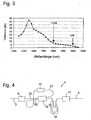
- Figure 3 shows the difference between the gain levels of the amplifier at full pump power and at 0 pump power as a function of the wavelength.
- a wavelength of e.g. 1580 nm which is far outside the frequency range used for the payload channels, this difference is still 7.3 dB.
- 1615 nm it is already below 3 dB, and at 1620 nm it is approx. 2 dB. Only from approx. 1630 nm onwards, there is practically no difference.
- the output of amplifier 11 or control unit 16 to the exit of the network node, or between source and sink of network nodes connected by an optical fibre such as fibre 3, is the stronger, the longer the wavelength is.
- the wavelength of the supervisory channel must be chosen in a range where the dependence of the gain in the amplifiers from the pumping state is small but not yet exactly 0. Obviously, such a wavelength is dependent on the design of the network nodes and the materials used therein, and, eventually, on the material of the optical fibre.
- wavelengths from 1600 nm in particular in the range of 1610 to 1650 nm and in particular 1620 to 1630 nm have proven appropriate. If a gain-equalizing filter is used, eventually in combination with other active media, other limit wavelengths may prove appropriate.
- FIG 4 is a block diagram showing the structure of an alternative design of a network node 1 that functions exclusively as an amplifier.
- the demultiplexer 10 and multiplexer 12 of Figure 1 are here merged into a continuous, wavelength-selectively reflecting structure 18 having four gates, which receives the incoming wavelength-division multiplex signal at a first gate 19 from the pre-amplifier 8, outputs its optical supervisory channel at a second gate 20 to the amplifier 11, receives the amplified supervisory channel at the third gate 21 and outputs it, recombined with the payload channels, at a fourth gate 22 via a dispersion compensator 23 to the post-amplifier 13.
- Such a four-gate structure 18 may easily be formed, for example, by an optical integrated Bragg grating, the grating constant of which is selected so as to reflect the supervisory channel and to transmit the payload channels.
Landscapes
- Engineering & Computer Science (AREA)
- Computer Networks & Wireless Communication (AREA)
- Signal Processing (AREA)
- Physics & Mathematics (AREA)
- Electromagnetism (AREA)
- Optical Communication System (AREA)
- Lasers (AREA)
- Glass Compositions (AREA)
Applications Claiming Priority (2)
| Application Number | Priority Date | Filing Date | Title |
|---|---|---|---|
| DE10349891A DE10349891A1 (de) | 2003-10-25 | 2003-10-25 | Optisches Netzwerk und Verstärkerknoten dafür |
| PCT/EP2004/052641 WO2005041451A1 (en) | 2003-10-25 | 2004-10-22 | Optical network and amplifier node therefore |
Publications (2)
| Publication Number | Publication Date |
|---|---|
| EP1687918A1 EP1687918A1 (en) | 2006-08-09 |
| EP1687918B1 true EP1687918B1 (en) | 2007-05-02 |
Family
ID=34485062
Family Applications (1)
| Application Number | Title | Priority Date | Filing Date |
|---|---|---|---|
| EP04791296A Expired - Lifetime EP1687918B1 (en) | 2003-10-25 | 2004-10-22 | Optical network and amplifier node therefor |
Country Status (7)
| Country | Link |
|---|---|
| US (1) | US7831148B2 (enExample) |
| EP (1) | EP1687918B1 (enExample) |
| JP (1) | JP4607892B2 (enExample) |
| CN (1) | CN1918829B (enExample) |
| AT (1) | ATE361598T1 (enExample) |
| DE (2) | DE10349891A1 (enExample) |
| WO (1) | WO2005041451A1 (enExample) |
Families Citing this family (3)
| Publication number | Priority date | Publication date | Assignee | Title |
|---|---|---|---|---|
| US8891957B2 (en) * | 2011-07-13 | 2014-11-18 | Tyco Electronics Subsea Communications Llc | Method and system for fault recovery in an optical network |
| US10341039B1 (en) * | 2016-12-28 | 2019-07-02 | Juniper Networks, Inc. | Methods and apparatus for separating the wavelength switching function from the channel equalization function in a reconfigurable optical add/drop multiplexer (ROADM) |
| CN119519883A (zh) * | 2024-10-29 | 2025-02-25 | 浙江海数科技有限公司 | 利用波分复用技术的异地通信平台 |
Family Cites Families (18)
| Publication number | Priority date | Publication date | Assignee | Title |
|---|---|---|---|---|
| US5532864A (en) * | 1995-06-01 | 1996-07-02 | Ciena Corporation | Optical monitoring channel for wavelength division multiplexed optical communication system |
| JP4036489B2 (ja) * | 1995-08-23 | 2008-01-23 | 富士通株式会社 | 波長多重信号を光増幅する光増幅器を制御するための方法と装置 |
| KR100219719B1 (ko) * | 1997-07-15 | 1999-09-01 | 윤종용 | 감시가능한 파장분할다중화 광증폭기 제어시스템 및 그 제어방법 |
| US6381049B1 (en) * | 1997-12-15 | 2002-04-30 | Ditech Corporation | Multi-port optical multiplexer element |
| FR2776440A1 (fr) * | 1998-03-17 | 1999-09-24 | Nec Corp | Circuit de derivation optique de signal de supervision, repeteur d'amplification optique et systeme de supervision |
| US6057959A (en) * | 1998-05-22 | 2000-05-02 | Ciena Corporation | Optical amplifier having substantially uniform spectral gain |
| US6411407B1 (en) * | 1998-09-17 | 2002-06-25 | Alcatel | Method for providing a bidirectional optical supervisory channel |
| US6362916B2 (en) * | 1998-09-25 | 2002-03-26 | Fiver Laboratories | All fiber gain flattening optical filter |
| JP3670156B2 (ja) * | 1999-03-18 | 2005-07-13 | 富士通株式会社 | 監視光信号を伝送するための方法、装置及びシステム |
| US6885824B1 (en) * | 2000-03-03 | 2005-04-26 | Optical Coating Laboratory, Inc. | Expandable optical array |
| GB2362525B (en) * | 2000-05-18 | 2002-07-24 | Marconi Comm Ltd | Radiation power equalization in wavelength division multiplexing (WDM) optical communication system |
| US6766113B1 (en) * | 2000-06-16 | 2004-07-20 | Lucent Technologies Inc. | Control channel processor and switching mechanism |
| US6623185B1 (en) * | 2000-06-16 | 2003-09-23 | Lucent Technologies Inc. | Loss of signal detector for low-level optical signals |
| WO2002091027A2 (en) * | 2001-05-09 | 2002-11-14 | Ciena Corporation | Method and system for controlling amplifier power in an optical communications network having add/drop capability |
| JP4481540B2 (ja) * | 2001-12-07 | 2010-06-16 | 富士通株式会社 | 光増幅器 |
| FR2838190B1 (fr) * | 2002-04-08 | 2004-10-15 | Cit Alcatel | Dispositif de mesure et/ou de controle dynamique de perte de puissance dans une ligne de transmission optique a canal de supervision, et procede associe |
| DE10335419A1 (de) * | 2003-08-02 | 2005-02-17 | Marconi Communications Gmbh | Wellenlängenselektive optische Signalverarbeitungsvorrichtung |
| CN1314036C (zh) * | 2004-01-15 | 2007-05-02 | 华硕电脑股份有限公司 | 可减少托盘水平偏摆的方法及光驱 |
-
2003
- 2003-10-25 DE DE10349891A patent/DE10349891A1/de not_active Withdrawn
-
2004
- 2004-10-22 EP EP04791296A patent/EP1687918B1/en not_active Expired - Lifetime
- 2004-10-22 WO PCT/EP2004/052641 patent/WO2005041451A1/en not_active Ceased
- 2004-10-22 US US10/576,640 patent/US7831148B2/en not_active Expired - Fee Related
- 2004-10-22 JP JP2006536097A patent/JP4607892B2/ja not_active Expired - Fee Related
- 2004-10-22 AT AT04791296T patent/ATE361598T1/de not_active IP Right Cessation
- 2004-10-22 CN CN2004800315133A patent/CN1918829B/zh not_active Expired - Fee Related
- 2004-10-22 DE DE602004006298T patent/DE602004006298T2/de not_active Expired - Lifetime
Also Published As
| Publication number | Publication date |
|---|---|
| WO2005041451A1 (en) | 2005-05-06 |
| US7831148B2 (en) | 2010-11-09 |
| ATE361598T1 (de) | 2007-05-15 |
| JP4607892B2 (ja) | 2011-01-05 |
| DE602004006298T2 (de) | 2007-12-27 |
| DE602004006298D1 (de) | 2007-06-14 |
| CN1918829B (zh) | 2010-12-29 |
| US20070274723A1 (en) | 2007-11-29 |
| EP1687918A1 (en) | 2006-08-09 |
| DE10349891A1 (de) | 2005-05-25 |
| JP2007509555A (ja) | 2007-04-12 |
| CN1918829A (zh) | 2007-02-21 |
Similar Documents
| Publication | Publication Date | Title |
|---|---|---|
| KR101364960B1 (ko) | 양방향성 광학 증폭기 어레이 | |
| US6052219A (en) | Wide bandwidth Raman amplifier capable of employing pump energy spectrally overlapping the signal | |
| US5532864A (en) | Optical monitoring channel for wavelength division multiplexed optical communication system | |
| US6091540A (en) | Optical amplifier | |
| US9641242B2 (en) | Optical communication system, device and method for data processing in an optical network | |
| US6411407B1 (en) | Method for providing a bidirectional optical supervisory channel | |
| CN100375416C (zh) | 波分复用光通信系统的插入/分出多路复用器和均衡方法 | |
| US5801878A (en) | Circuit having two optical amplifiers, in particular for a repeater in an undersea telecommunications system | |
| EP0851617A2 (en) | Optical arrangement for amplifying WDM signals | |
| US6480328B2 (en) | Optical amplifier and optical amplification method for amplifying wavelength division multiplexed signal light | |
| US6256140B1 (en) | Optical amplifying apparatus for transmitting wavelength division multiplexed signal light and optical network apparatus with using the same | |
| US6735394B1 (en) | Per-channel optical amplification using saturation mode | |
| US7831148B2 (en) | Optical network and amplifier node therefore | |
| KR100396510B1 (ko) | 분산 보상된 광섬유 증폭기 | |
| JPWO2018207835A1 (ja) | 光中継器、光中継器の制御方法、及び光伝送システム | |
| JP3149916B2 (ja) | 波長多重光中継増幅装置 | |
| US6501870B1 (en) | System and method for reducing effects of optical impairments in optically amplified lightwave communication systems | |
| US6577416B1 (en) | Channel control in a wavelength division multiplexed communications network | |
| US7145716B2 (en) | Multiple stage Raman optical amplifier | |
| JP2000077757A (ja) | 光増幅器、光伝送装置および光伝送システム | |
| WO2000051278A1 (en) | Wdm ring transmission system having amplified dropped channels | |
| EP1654816B1 (en) | Wavelength-selective optical signal processing device | |
| US20060120725A1 (en) | Optical interface devices for optical communications | |
| CN121864247A (zh) | 光复用段、光通信系统和光放大器 | |
| KR20020094815A (ko) | 양방향 광 선로쌍에서의 양방향 광 증폭기 |
Legal Events
| Date | Code | Title | Description |
|---|---|---|---|
| PUAI | Public reference made under article 153(3) epc to a published international application that has entered the european phase |
Free format text: ORIGINAL CODE: 0009012 |
|
| 17P | Request for examination filed |
Effective date: 20060407 |
|
| AK | Designated contracting states |
Kind code of ref document: A1 Designated state(s): AT BE BG CH CY CZ DE DK EE ES FI FR GB GR HU IE IT LI LU MC NL PL PT RO SE SI SK TR |
|
| GRAP | Despatch of communication of intention to grant a patent |
Free format text: ORIGINAL CODE: EPIDOSNIGR1 |
|
| DAX | Request for extension of the european patent (deleted) | ||
| RAP1 | Party data changed (applicant data changed or rights of an application transferred) |
Owner name: ERICSSON AB |
|
| GRAS | Grant fee paid |
Free format text: ORIGINAL CODE: EPIDOSNIGR3 |
|
| GRAA | (expected) grant |
Free format text: ORIGINAL CODE: 0009210 |
|
| AK | Designated contracting states |
Kind code of ref document: B1 Designated state(s): AT BE BG CH CY CZ DE DK EE ES FI FR GB GR HU IE IT LI LU MC NL PL PT RO SE SI SK TR |
|
| PG25 | Lapsed in a contracting state [announced via postgrant information from national office to epo] |
Ref country code: LI Free format text: LAPSE BECAUSE OF FAILURE TO SUBMIT A TRANSLATION OF THE DESCRIPTION OR TO PAY THE FEE WITHIN THE PRESCRIBED TIME-LIMIT Effective date: 20070502 Ref country code: FI Free format text: LAPSE BECAUSE OF FAILURE TO SUBMIT A TRANSLATION OF THE DESCRIPTION OR TO PAY THE FEE WITHIN THE PRESCRIBED TIME-LIMIT Effective date: 20070502 Ref country code: CH Free format text: LAPSE BECAUSE OF FAILURE TO SUBMIT A TRANSLATION OF THE DESCRIPTION OR TO PAY THE FEE WITHIN THE PRESCRIBED TIME-LIMIT Effective date: 20070502 |
|
| REG | Reference to a national code |
Ref country code: GB Ref legal event code: FG4D |
|
| REG | Reference to a national code |
Ref country code: CH Ref legal event code: EP |
|
| REG | Reference to a national code |
Ref country code: IE Ref legal event code: FG4D |
|
| REF | Corresponds to: |
Ref document number: 602004006298 Country of ref document: DE Date of ref document: 20070614 Kind code of ref document: P |
|
| PG25 | Lapsed in a contracting state [announced via postgrant information from national office to epo] |
Ref country code: SE Free format text: LAPSE BECAUSE OF FAILURE TO SUBMIT A TRANSLATION OF THE DESCRIPTION OR TO PAY THE FEE WITHIN THE PRESCRIBED TIME-LIMIT Effective date: 20070802 |
|
| PG25 | Lapsed in a contracting state [announced via postgrant information from national office to epo] |
Ref country code: ES Free format text: LAPSE BECAUSE OF FAILURE TO SUBMIT A TRANSLATION OF THE DESCRIPTION OR TO PAY THE FEE WITHIN THE PRESCRIBED TIME-LIMIT Effective date: 20070813 |
|
| ET | Fr: translation filed | ||
| NLV1 | Nl: lapsed or annulled due to failure to fulfill the requirements of art. 29p and 29m of the patents act | ||
| REG | Reference to a national code |
Ref country code: CH Ref legal event code: PL |
|
| PG25 | Lapsed in a contracting state [announced via postgrant information from national office to epo] |
Ref country code: PL Free format text: LAPSE BECAUSE OF FAILURE TO SUBMIT A TRANSLATION OF THE DESCRIPTION OR TO PAY THE FEE WITHIN THE PRESCRIBED TIME-LIMIT Effective date: 20070502 Ref country code: AT Free format text: LAPSE BECAUSE OF FAILURE TO SUBMIT A TRANSLATION OF THE DESCRIPTION OR TO PAY THE FEE WITHIN THE PRESCRIBED TIME-LIMIT Effective date: 20070502 |
|
| PG25 | Lapsed in a contracting state [announced via postgrant information from national office to epo] |
Ref country code: BE Free format text: LAPSE BECAUSE OF FAILURE TO SUBMIT A TRANSLATION OF THE DESCRIPTION OR TO PAY THE FEE WITHIN THE PRESCRIBED TIME-LIMIT Effective date: 20070502 |
|
| PG25 | Lapsed in a contracting state [announced via postgrant information from national office to epo] |
Ref country code: BG Free format text: LAPSE BECAUSE OF FAILURE TO SUBMIT A TRANSLATION OF THE DESCRIPTION OR TO PAY THE FEE WITHIN THE PRESCRIBED TIME-LIMIT Effective date: 20070802 Ref country code: PT Free format text: LAPSE BECAUSE OF FAILURE TO SUBMIT A TRANSLATION OF THE DESCRIPTION OR TO PAY THE FEE WITHIN THE PRESCRIBED TIME-LIMIT Effective date: 20071002 Ref country code: DK Free format text: LAPSE BECAUSE OF FAILURE TO SUBMIT A TRANSLATION OF THE DESCRIPTION OR TO PAY THE FEE WITHIN THE PRESCRIBED TIME-LIMIT Effective date: 20070502 Ref country code: NL Free format text: LAPSE BECAUSE OF FAILURE TO SUBMIT A TRANSLATION OF THE DESCRIPTION OR TO PAY THE FEE WITHIN THE PRESCRIBED TIME-LIMIT Effective date: 20070502 Ref country code: CZ Free format text: LAPSE BECAUSE OF FAILURE TO SUBMIT A TRANSLATION OF THE DESCRIPTION OR TO PAY THE FEE WITHIN THE PRESCRIBED TIME-LIMIT Effective date: 20070502 Ref country code: SI Free format text: LAPSE BECAUSE OF FAILURE TO SUBMIT A TRANSLATION OF THE DESCRIPTION OR TO PAY THE FEE WITHIN THE PRESCRIBED TIME-LIMIT Effective date: 20070502 |
|
| PG25 | Lapsed in a contracting state [announced via postgrant information from national office to epo] |
Ref country code: SK Free format text: LAPSE BECAUSE OF FAILURE TO SUBMIT A TRANSLATION OF THE DESCRIPTION OR TO PAY THE FEE WITHIN THE PRESCRIBED TIME-LIMIT Effective date: 20070502 |
|
| PLBE | No opposition filed within time limit |
Free format text: ORIGINAL CODE: 0009261 |
|
| STAA | Information on the status of an ep patent application or granted ep patent |
Free format text: STATUS: NO OPPOSITION FILED WITHIN TIME LIMIT |
|
| 26N | No opposition filed |
Effective date: 20080205 |
|
| PG25 | Lapsed in a contracting state [announced via postgrant information from national office to epo] |
Ref country code: GR Free format text: LAPSE BECAUSE OF FAILURE TO SUBMIT A TRANSLATION OF THE DESCRIPTION OR TO PAY THE FEE WITHIN THE PRESCRIBED TIME-LIMIT Effective date: 20070803 |
|
| PG25 | Lapsed in a contracting state [announced via postgrant information from national office to epo] |
Ref country code: RO Free format text: LAPSE BECAUSE OF FAILURE TO SUBMIT A TRANSLATION OF THE DESCRIPTION OR TO PAY THE FEE WITHIN THE PRESCRIBED TIME-LIMIT Effective date: 20070502 Ref country code: MC Free format text: LAPSE BECAUSE OF NON-PAYMENT OF DUE FEES Effective date: 20071031 |
|
| PG25 | Lapsed in a contracting state [announced via postgrant information from national office to epo] |
Ref country code: IE Free format text: LAPSE BECAUSE OF NON-PAYMENT OF DUE FEES Effective date: 20071022 |
|
| PG25 | Lapsed in a contracting state [announced via postgrant information from national office to epo] |
Ref country code: EE Free format text: LAPSE BECAUSE OF FAILURE TO SUBMIT A TRANSLATION OF THE DESCRIPTION OR TO PAY THE FEE WITHIN THE PRESCRIBED TIME-LIMIT Effective date: 20070502 |
|
| PG25 | Lapsed in a contracting state [announced via postgrant information from national office to epo] |
Ref country code: CY Free format text: LAPSE BECAUSE OF FAILURE TO SUBMIT A TRANSLATION OF THE DESCRIPTION OR TO PAY THE FEE WITHIN THE PRESCRIBED TIME-LIMIT Effective date: 20070502 |
|
| PG25 | Lapsed in a contracting state [announced via postgrant information from national office to epo] |
Ref country code: LU Free format text: LAPSE BECAUSE OF NON-PAYMENT OF DUE FEES Effective date: 20071022 |
|
| PG25 | Lapsed in a contracting state [announced via postgrant information from national office to epo] |
Ref country code: HU Free format text: LAPSE BECAUSE OF FAILURE TO SUBMIT A TRANSLATION OF THE DESCRIPTION OR TO PAY THE FEE WITHIN THE PRESCRIBED TIME-LIMIT Effective date: 20071103 Ref country code: TR Free format text: LAPSE BECAUSE OF FAILURE TO SUBMIT A TRANSLATION OF THE DESCRIPTION OR TO PAY THE FEE WITHIN THE PRESCRIBED TIME-LIMIT Effective date: 20070502 |
|
| PGFP | Annual fee paid to national office [announced via postgrant information from national office to epo] |
Ref country code: IT Payment date: 20071031 Year of fee payment: 4 |
|
| PGFP | Annual fee paid to national office [announced via postgrant information from national office to epo] |
Ref country code: DE Payment date: 20141029 Year of fee payment: 11 Ref country code: GB Payment date: 20141027 Year of fee payment: 11 |
|
| REG | Reference to a national code |
Ref country code: FR Ref legal event code: PLFP Year of fee payment: 12 |
|
| PGFP | Annual fee paid to national office [announced via postgrant information from national office to epo] |
Ref country code: FR Payment date: 20151019 Year of fee payment: 12 |
|
| REG | Reference to a national code |
Ref country code: DE Ref legal event code: R119 Ref document number: 602004006298 Country of ref document: DE |
|
| GBPC | Gb: european patent ceased through non-payment of renewal fee |
Effective date: 20151022 |
|
| PG25 | Lapsed in a contracting state [announced via postgrant information from national office to epo] |
Ref country code: DE Free format text: LAPSE BECAUSE OF NON-PAYMENT OF DUE FEES Effective date: 20160503 Ref country code: GB Free format text: LAPSE BECAUSE OF NON-PAYMENT OF DUE FEES Effective date: 20151022 |
|
| REG | Reference to a national code |
Ref country code: FR Ref legal event code: ST Effective date: 20170630 |
|
| PG25 | Lapsed in a contracting state [announced via postgrant information from national office to epo] |
Ref country code: FR Free format text: LAPSE BECAUSE OF NON-PAYMENT OF DUE FEES Effective date: 20161102 |