EP1686908B1 - Catheter, in particular for ablation and like techniques - Google Patents
Catheter, in particular for ablation and like techniques Download PDFInfo
- Publication number
- EP1686908B1 EP1686908B1 EP04793666.1A EP04793666A EP1686908B1 EP 1686908 B1 EP1686908 B1 EP 1686908B1 EP 04793666 A EP04793666 A EP 04793666A EP 1686908 B1 EP1686908 B1 EP 1686908B1
- Authority
- EP
- European Patent Office
- Prior art keywords
- catheter
- channel
- tip
- outlet opening
- cooling fluid
- Prior art date
- Legal status (The legal status is an assumption and is not a legal conclusion. Google has not performed a legal analysis and makes no representation as to the accuracy of the status listed.)
- Not-in-force
Links
Images

Classifications
-
- A—HUMAN NECESSITIES
- A61—MEDICAL OR VETERINARY SCIENCE; HYGIENE
- A61B—DIAGNOSIS; SURGERY; IDENTIFICATION
- A61B18/00—Surgical instruments, devices or methods for transferring non-mechanical forms of energy to or from the body
- A61B18/04—Surgical instruments, devices or methods for transferring non-mechanical forms of energy to or from the body by heating
- A61B18/12—Surgical instruments, devices or methods for transferring non-mechanical forms of energy to or from the body by heating by passing a current through the tissue to be heated, e.g. high-frequency current
- A61B18/14—Probes or electrodes therefor
- A61B18/1492—Probes or electrodes therefor having a flexible, catheter-like structure, e.g. for heart ablation
-
- A—HUMAN NECESSITIES
- A61—MEDICAL OR VETERINARY SCIENCE; HYGIENE
- A61B—DIAGNOSIS; SURGERY; IDENTIFICATION
- A61B18/00—Surgical instruments, devices or methods for transferring non-mechanical forms of energy to or from the body
- A61B18/04—Surgical instruments, devices or methods for transferring non-mechanical forms of energy to or from the body by heating
- A61B18/12—Surgical instruments, devices or methods for transferring non-mechanical forms of energy to or from the body by heating by passing a current through the tissue to be heated, e.g. high-frequency current
- A61B18/14—Probes or electrodes therefor
-
- A—HUMAN NECESSITIES
- A61—MEDICAL OR VETERINARY SCIENCE; HYGIENE
- A61M—DEVICES FOR INTRODUCING MEDIA INTO, OR ONTO, THE BODY; DEVICES FOR TRANSDUCING BODY MEDIA OR FOR TAKING MEDIA FROM THE BODY; DEVICES FOR PRODUCING OR ENDING SLEEP OR STUPOR
- A61M25/00—Catheters; Hollow probes
- A61M25/01—Introducing, guiding, advancing, emplacing or holding catheters
-
- A—HUMAN NECESSITIES
- A61—MEDICAL OR VETERINARY SCIENCE; HYGIENE
- A61B—DIAGNOSIS; SURGERY; IDENTIFICATION
- A61B18/00—Surgical instruments, devices or methods for transferring non-mechanical forms of energy to or from the body
- A61B2018/00005—Cooling or heating of the probe or tissue immediately surrounding the probe
- A61B2018/00011—Cooling or heating of the probe or tissue immediately surrounding the probe with fluids
- A61B2018/00029—Cooling or heating of the probe or tissue immediately surrounding the probe with fluids open
-
- A—HUMAN NECESSITIES
- A61—MEDICAL OR VETERINARY SCIENCE; HYGIENE
- A61B—DIAGNOSIS; SURGERY; IDENTIFICATION
- A61B18/00—Surgical instruments, devices or methods for transferring non-mechanical forms of energy to or from the body
- A61B2018/00053—Mechanical features of the instrument of device
- A61B2018/00059—Material properties
- A61B2018/00089—Thermal conductivity
- A61B2018/00101—Thermal conductivity low, i.e. thermally insulating
-
- A—HUMAN NECESSITIES
- A61—MEDICAL OR VETERINARY SCIENCE; HYGIENE
- A61B—DIAGNOSIS; SURGERY; IDENTIFICATION
- A61B18/00—Surgical instruments, devices or methods for transferring non-mechanical forms of energy to or from the body
- A61B2018/00315—Surgical instruments, devices or methods for transferring non-mechanical forms of energy to or from the body for treatment of particular body parts
- A61B2018/00345—Vascular system
- A61B2018/00351—Heart
- A61B2018/00363—Epicardium
-
- A—HUMAN NECESSITIES
- A61—MEDICAL OR VETERINARY SCIENCE; HYGIENE
- A61B—DIAGNOSIS; SURGERY; IDENTIFICATION
- A61B18/00—Surgical instruments, devices or methods for transferring non-mechanical forms of energy to or from the body
- A61B2018/00571—Surgical instruments, devices or methods for transferring non-mechanical forms of energy to or from the body for achieving a particular surgical effect
- A61B2018/00577—Ablation
-
- A—HUMAN NECESSITIES
- A61—MEDICAL OR VETERINARY SCIENCE; HYGIENE
- A61B—DIAGNOSIS; SURGERY; IDENTIFICATION
- A61B18/00—Surgical instruments, devices or methods for transferring non-mechanical forms of energy to or from the body
- A61B2018/00636—Sensing and controlling the application of energy
- A61B2018/00773—Sensed parameters
- A61B2018/00791—Temperature
- A61B2018/00815—Temperature measured by a thermistor
Definitions
- the invention relates to a catheter.
- the invention relates in particular to a catheter for ablation in body cavities such as blood vessels or organs such as a heart.
- the temperature of, in particular, said first end of the catheter can be controlled in order to evaluate the amount of warming of the target area; hence, based on inter alia this temperature, the power which is to be supplied to this first end can be controlled.
- the abutment of said first end against the wall can be assessed based on the temperature increase which is measured in said first end. In fact, a less good abutment will lead to a smaller temperature increase when the power supplied remains the same.
- the temperature in the fluid, in particular blood is to be prevented from rising too much around said first end because clogging can occur as a result thereof, which clogging can lead to dangerous situations in the body.
- too strong a heating of the first end of the catheter can lead to blistering, explosions due to boiling of entrapped liquid in the wall of the respective cavity such as the heart, which is dangerous to the health and, in extreme cases, can lead to openings in the heart wall, while, furthermore, the danger exists that undesirably large areas are affected, as a result of which damage to, for instance, an AV-node can occur.
- a temperature sensor such as a thermocouple in said first end.
- thermocouple in said first end of such a catheter.
- the temperature measurement is inaccurate. Consequently, the temperature change of said first end and, hence, of for instance the fluid, in particular the blood around said first end or the temperature of the wall, cannot be verified sufficiently accurately, so that clots can still occur, while, moreover, the extent of the temperature increase of the wall cannot be sufficiently controlled and verified.
- the first end of this catheter remains relatively cool, no deposits of such clots will be detected on said exterior, which entails the risk that it can be wrongfully assumed that no clots have formed during the treatment.
- the fluid, in particular the blood around said first end and/or the wall may very well have been heated such that coagulation has occurred, resulting in clots.
- a catheter is provided with a closed channel extending through said first end, with which the first end is cooled from the inside.
- the invention aims to provide a catheter with which treatments that require local heating of a body cavity wall, such as ablation, can be performed in a safe and accurate manner.
- the invention furthermore aims to provide such a catheter with which abutment of a first end thereof against a wall can be assessed during use in a simple and accurate manner.
- a further object of the invention is to provide a catheter with which, the first, leading end can be heated during use in a simple and accurate manner, in particular with the aid of current, whereby clots can be prevented in a simple manner.
- the invention further aims to provide a catheter which is compatible with existing devices for ablation techniques.
- a thermal separation is provided between the channel and the electrode.
- This thermal separation is provided such that fluid flowing through the channel during use substantially does not come into contact with the electrode before it flows out of at least one first outflow opening.
- a catheter is further characterized in that said channel has a longitudinal direction and is provided with a series of outlet openings, which outlet openings are positioned such that cooling medium supplied, during use, through said channel flows through said outlet openings in an outflow direction, which forms an angle with said longitudinal direction.
- This angle is for instance between 30° and 90°, more particularly between 45° and 90°, so that the outflow direction is directed substantially away from the outside of the first end.
- an outlet opening can also be provided in the axially leading end of said first end.
- one or more outlet openings can be provided in a leading longitudinal edge of said body, such that during use, a flow is obtained substantially along the outside surface of said first end.
- the respective at least one outlet opening can be located adjacent said first end, when viewed in front view.
- the or each outlet opening is implemented such that a somewhat turbulent flow is created around said first end, so that coagulation is prevented even better.
- thermally poorly-conductive is understood to at least include heat transfer across the wall of the channel to the first end which is considerably less, for instance 10% or more, more particularly 25% or more, than the heat transfer across the wall of a channel which would occur with a similar catheter of similar dimensions, but not having such thermally-insulating features.
- the temperature sensor which can for instance be implemented in a known manner as a thermocouple, is incorporated in the first end preferably at a distance from the interface between said first end and the body of the catheter, preferably adjacent the middle of the electrode. As a result, an accurate temperature measurement of said first end becomes possible. With automatically performed treatments, this sensor can also be used as a switch.
- the first end can be manufactured from a thermally and electrically conductive material such as metal. Also, only an outer casing can be provided with metal, on, for instance, a plastic, ceramic or glass core, whereby a part of the desired thermal insulation can be obtained from the core.
- the invention may be utilized in a method for thermal treatment such as ablation.
- the temperature of a first end of an ablation catheter can be more accurately checked and controlled, so that ablations and other thermal treatments can be accurately and safely performed in body cavities such as blood vessels, a heart and the like.
- the temperature of a wall part of a body cavity can be especially accurately controlled, without the danger arising that coagulation occurs in the blood flowing around said wall part. Coagulation of proteins in the blood can lead to clot formation, which clots can become dislodged in the blood flow and can lead, for instance, to infarcts. Clots are to be avoided, in particular, in the left ventricle and atrium of the heart.
- the temperature of the blood around said wall part is preferably kept below the coagulation temperature, while the tip of the employed catheter and/or the to-be-treated wall part can be heated to the desired, possibly higher, temperature.
- the or each electrode is thereby heated substantially by the adjacent wall, wherein a temperature increase occurs as a result of resistance.
- the extent of contact between the wall and the electrode will therefore influence the heating of the electrode. This is a reason why a contact measurement can be important.
- a cooling fluid such as a physiological saline solution is supplied, preferably in a known manner, through a channel extending through the catheter, which cooling fluid is directly introduced into the respective body cavity.
- the cooling fluid is preferably thermally insulated to a high extent from the material of the leading first end of the catheter during use, so that the blood around this first end is cooled more intensively than the first end itself.
- the temperature of the first end is measured accurately thereby, whereby the temperature of the wall, against which or at which the catheter is held, can be accurately controlled.
- the temperature of the blood around said first end is preferably kept lower than approximately 55°C.
- the temperature of the outside of the first end is thereby preferably kept below approximately 65°C.
- turbulence is preferably generated in the blood around said first end, whereby clot formation in the blood is prevented even better.
- a body cavity is understood herein to include at least each part of a human or animal body which can be reached by a forward end of a catheter.
- Fig. 1 it is schematically shown how a catheter 1 has been inserted into a heart 2 of a patient 3.
- a forward end 4 of a catheter 1A is inserted into a ventricle 5, in particular a right ventricle of the heart, while the corresponding forward end 4 of a second catheter 1B is inserted into the right atrium 6 of the heart 2.
- the catheter(s) is or are inserted into the heart 2 from, for instance, the groin of the patient 3, which is a known method and will therefore not be described further; the known method and device for controlling these catheters and the mechanisms thereto in the catheter also will not be described.
- a heart 2 is shown in cross section with the left and right ventricle 5A, 5B and the left and right atrium 6A, 6B.
- catheters 1 have been inserted into this heart 2.
- one or more catheters 1 can be inserted into the heart 2, in order to obtain a clear picture of the electric currents in the heart.
- Each of the depicted catheters 1 has a body 7 which is elongated and can be guided through the vascular system of the patient.
- the body 7 has a forward end 4, hereinafter called the first end 4, which is inserted into the heart 2.
- a number of electrodes 8 are provided in the form of metal rings, for instance three, which are separated from each other by electrically insulating material of the body and each can be connected with electronic equipment via a conductive wire through the body 7, so that measurements can be carried out in a known manner, for instance an electrogram can be made.
- the first end 4 is further provided with a tip 9 manufactured from an electrically conductive material such as metal, which tip can be connected via an electrically-conductive wire 10 ( Figs. 3 -6) with said electronic equipment (not shown), with which current can be fed via the wire 10 into said tip 9.
- the patient lies on an electrically conductive sub-surface, for instance on a grounding plate (not shown).
- the tip 9 of the catheter 1 is pressed against the wall 11 of the heart 2, so that a current will start to flow through said wall 11.
- a cooling fluid in a catheter 1 for use in, for instance, ablation techniques.
- This cooling fluid is brought through a channel in the catheter to the forward end of the catheter and from there, it is either introduced into the blood stream or returned through the catheter.
- the cooling fluid is thereby brought against the inside of the catheter into close contact with the to-be-cooled electrode, such as the tip of the catheter, in order to cool this electrode and thereby prevent deposition of proteins on the outside.
- Such a catheter is, for instance, described in EP 0 856 292 .
- such catheters have the disadvantage that the temperature of the respective electrode, such as the tip, no longer offers a good representation of the heat development in said wall 11 and/or in the blood B around said electrode.
- a first embodiment of a forward end of a catheter 1 according to the invention is shown, in cross-sectional side view.
- This catheter 1 comprises an elongated body 7 with a first end 4, formed by a tip 9 made of an electrically and thermally conductive material, in particular metal such as platinum.
- the body has a longitudinal axis A-A and comprises a substantially cylindrical wall 12 through which a channel 13 extends. Between the wall 12 and the channel 13, there is an annular space 14 through which extends, for instance, the electrically conductive wire 10, the different connecting points for the electrodes 8 and known control means (not shown) for controlling the end 4.
- a second electrically-conductive wire 15 extends through the annular space 14, which wire 15 is connected to a thermocouple 16.
- the tip 9 is coupled to the body 7 by means of a coupling part 18 which is attached, for instance glued, to a first side inside the wall 12, and, on the other side, is fitted in a compatible second snap edge 20 of the tip 9 via a snap edge 19.
- the thermocouple 16 is arranged in or against the interface 17 between the body 7 and the tip 9, at least on the end surface 21 of the tip 9 proximal to the body 7 and the coupling part 18.
- a channel part 22 is provided extending in line with the axis A-A and is connected to the channel 13, for instance because a sleeve 23 extends from said end surface 21 in the channel 13 and is fitted therein.
- first bores 24 are provided reaching into the channel part 22 and extending substantially radially. These first bores 24 all have a longitudinal axis 25 forming an angle ⁇ with the longitudinal axis A-A of the body 7, for instance approximately 90°.
- a second bore 26 is provided in line with the channel 13, at least with the axis A-A, which bore 26 terminates in the apex 36 of the tip 9.
- a thermal insulating casing 27 is provided, such that during use a cooling fluid, in particular a physiological saline solution, can be passed through the channel 13, the channel part 22 and the bores 24, 26 without direct contact occurring between the cooling fluid and (the inside of) the tip 9. Direct cooling of the tip 9 by the cooling fluid is thereby prevented in large part.
- the sleeve 23 is not thermally insulated.
- a first, more advantageous alternative embodiment of a first end 4 of a catheter 1 according to the invention is shown, distinguished from the one according to Fig. 3 in that herein, the sleeve 23 is also thermally insulated, while the thermocouple 16 is also arranged closer to the apex 36 of the tip 9, whereby an even more accurate temperature measurement of, in particular, the heart wall can be performed.
- a tip 9 is provided herein that has a core 28, which is manufactured from a material having a low thermal and/or electrical conductivity, for instance glass, ceramic or plastic, and a casing 29 having good heat conductivity and/or electrical conductivity relative thereto.
- the bores 24, 26 have been provided with a thermal inner casing only in the casing 29, at least formed as part of the core 28, whereby the desired thermal insulation is obtained in a simple manner.
- the longitudinal axes 25 extend approximately tangentially relative to the channel part 22 ( Fig.
- thermocouple 16 is attached to the casing 29.
- each bore 24, 26 always forms an outflow opening 30 for cooling fluid.
- These outflow openings 30 can for instance be formed such that during use a turbulent flow is generated in the blood flowing by. Means that can be used therefor are known from fluid dynamics. For instance, thirteen outflow openings are provided in the depicted embodiments, but it will be clear that any desired number of outflow openings 30 can be provided.
- one or more outlet openings can be provided near the electrode, in particular near the interface 17 between the body 7 and the tip 9, so that a part of the cooling fluid is directed along the tip 9, at least along the outer surface of the electrode, for direct cooling of the blood and/or for generating turbulence.
- the current intensity and the supply of cooling fluid are preferably regulated such that the temperature of the blood around the tip 9 is kept below the coagulation temperature. In practice, this means below approximately 55°C, so that no coagulation occurs.
- the temperature of the tip 9 is regulated such that it does not exceed 65°C. In practice, this has appeared to be a reasonably safe limit.
- an area 40 is schematically indicated in the wall 11 wherein heat development occurs as a result of the current passed through the wall 11, as described earlier.
- this influenced area 40 depends on the current intensity used and the duration of the treatment and is only given as an indication.
- a catheter according to the invention can also be provided with several electrodes, at least one of which being provided with a cooling device according to the invention, with insulated outflow openings. Also, only one electrode can be provided at a distance from the end.
Description
- The invention relates to a catheter. The invention relates in particular to a catheter for ablation in body cavities such as blood vessels or organs such as a heart.
- It is known to perform treatments in a human or animal body with the aid of catheters having an electrically conductive first end. This ablation electrode is typically present on the end of the catheter. There are also embodiments with several ablation electrodes one behind the other on the catheter which is inserted into said cavity. The patient is then laid on a conductive plate, for instance a grounding plate. Then, an electric current is passed through the catheter, which current flows through the body. If the first end is held against or at a very short distance from a wall of the body cavity, said wall will be heated locally over a relatively small area as a result of the electrical resistance of the wall. Consequently, ablation occurs in said area. As a result thereof, part of the tissue of said wall dies. With this treatment, for instance cardiac arrhythmias can be treated and prevented in the future.
- During this known treatment, it is of importance that the temperature of, in particular, said first end of the catheter can be controlled in order to evaluate the amount of warming of the target area; hence, based on inter alia this temperature, the power which is to be supplied to this first end can be controlled. Moreover, prior to the actual treatment, with the aid of a relatively small amount of power, the abutment of said first end against the wall can be assessed based on the temperature increase which is measured in said first end. In fact, a less good abutment will lead to a smaller temperature increase when the power supplied remains the same. Moreover, the temperature in the fluid, in particular blood, is to be prevented from rising too much around said first end because clogging can occur as a result thereof, which clogging can lead to dangerous situations in the body. Moreover, too strong a heating of the first end of the catheter can lead to blistering, explosions due to boiling of entrapped liquid in the wall of the respective cavity such as the heart, which is dangerous to the health and, in extreme cases, can lead to openings in the heart wall, while, furthermore, the danger exists that undesirably large areas are affected, as a result of which damage to, for instance, an AV-node can occur. In order to be able to measure this temperature, it is known to include a temperature sensor such as a thermocouple in said first end.
- In order to prevent said first end of the catheter from being heated too strongly, it has been proposed to cool this first end. To that end, Wittkampf (Journal of the American College of Cardiology 1988, 11, p.17A) has described a catheter wherein a fluid channel is provided in the catheter, which channel terminates in outlet openings in said first end. A cooling medium such as physiological saline solution can be forced through said channel and provides continuous cooling of said first end during use. Thus, the temperature thereof can be kept low. However, a disadvantage of this known catheter is that the actual temperature of said first end cannot be accurately measured.
- In order to solve this disadvantage, it has already been proposed in
WO 96/36860 A - In an alternative known embodiment, a catheter is provided with a closed channel extending through said first end, with which the first end is cooled from the inside. Here, the same dangers arise as with the above-described catheter with which, moreover, the great drawback occurs in that the blood is not cooled at all.
- The invention aims to provide a catheter with which treatments that require local heating of a body cavity wall, such as ablation, can be performed in a safe and accurate manner.
- The invention furthermore aims to provide such a catheter with which abutment of a first end thereof against a wall can be assessed during use in a simple and accurate manner.
- A further object of the invention is to provide a catheter with which, the first, leading end can be heated during use in a simple and accurate manner, in particular with the aid of current, whereby clots can be prevented in a simple manner.
- The invention further aims to provide a catheter which is compatible with existing devices for ablation techniques.
- One or more of these objects is achieved with a catheter according to the invention as defined in
claim 1. - With a catheter according to the invention, a thermal separation is provided between the channel and the electrode. This thermal separation is provided such that fluid flowing through the channel during use substantially does not come into contact with the electrode before it flows out of at least one first outflow opening. Thus, during use, it is ensured that it is not the electrode that is cooled by said fluid, at least not directly, but rather the fluid extending therearound, in particular blood. With this, coagulation can be prevented while the temperature of the electrode can be accurately measured.
- In an advantageous preferred embodiment, a catheter is further characterized in that said channel has a longitudinal direction and is provided with a series of outlet openings, which outlet openings are positioned such that cooling medium supplied, during use, through said channel flows through said outlet openings in an outflow direction, which forms an angle with said longitudinal direction. This angle is for instance between 30° and 90°, more particularly between 45° and 90°, so that the outflow direction is directed substantially away from the outside of the first end. Furthermore, an outlet opening can also be provided in the axially leading end of said first end.
- In an alternative embodiment, one or more outlet openings can be provided in a leading longitudinal edge of said body, such that during use, a flow is obtained substantially along the outside surface of said first end. To that end, the respective at least one outlet opening can be located adjacent said first end, when viewed in front view. An advantage of such an embodiment can be, for instance, a simple construction, no channel extending through the respective first end and/or an advantageous outflow pattern.
- In an advantageous embodiment, the or each outlet opening is implemented such that a somewhat turbulent flow is created around said first end, so that coagulation is prevented even better.
- In a practical embodiment, at least in and/or adjacent the first end, the channel and/or the outlet openings are provided with a thermally-insulating inner casing and/or are formed in a thermally poorly-conductive material. Herein, thermally poorly-conductive is understood to at least include heat transfer across the wall of the channel to the first end which is considerably less, for
instance 10% or more, more particularly 25% or more, than the heat transfer across the wall of a channel which would occur with a similar catheter of similar dimensions, but not having such thermally-insulating features. - The temperature sensor, which can for instance be implemented in a known manner as a thermocouple, is incorporated in the first end preferably at a distance from the interface between said first end and the body of the catheter, preferably adjacent the middle of the electrode. As a result, an accurate temperature measurement of said first end becomes possible. With automatically performed treatments, this sensor can also be used as a switch.
- The first end can be manufactured from a thermally and electrically conductive material such as metal. Also, only an outer casing can be provided with metal, on, for instance, a plastic, ceramic or glass core, whereby a part of the desired thermal insulation can be obtained from the core.
- The invention may be utilized in a method for thermal treatment such as ablation.
- With such a method, the temperature of a first end of an ablation catheter can be more accurately checked and controlled, so that ablations and other thermal treatments can be accurately and safely performed in body cavities such as blood vessels, a heart and the like. In addition, the temperature of a wall part of a body cavity can be especially accurately controlled, without the danger arising that coagulation occurs in the blood flowing around said wall part. Coagulation of proteins in the blood can lead to clot formation, which clots can become dislodged in the blood flow and can lead, for instance, to infarcts. Clots are to be avoided, in particular, in the left ventricle and atrium of the heart. With such a method, the temperature of the blood around said wall part is preferably kept below the coagulation temperature, while the tip of the employed catheter and/or the to-be-treated wall part can be heated to the desired, possibly higher, temperature. The or each electrode is thereby heated substantially by the adjacent wall, wherein a temperature increase occurs as a result of resistance. The extent of contact between the wall and the electrode will therefore influence the heating of the electrode. This is a reason why a contact measurement can be important.
- With this method, a cooling fluid such as a physiological saline solution is supplied, preferably in a known manner, through a channel extending through the catheter, which cooling fluid is directly introduced into the respective body cavity. The cooling fluid is preferably thermally insulated to a high extent from the material of the leading first end of the catheter during use, so that the blood around this first end is cooled more intensively than the first end itself. Preferably, the temperature of the first end is measured accurately thereby, whereby the temperature of the wall, against which or at which the catheter is held, can be accurately controlled.
- With the aid of said cooling fluid, the temperature of the blood around said first end is preferably kept lower than approximately 55°C. The temperature of the outside of the first end is thereby preferably kept below approximately 65°C.
- With the aid of the cooling fluid, turbulence is preferably generated in the blood around said first end, whereby clot formation in the blood is prevented even better.
- In the further subclaims, further advantageous embodiments of the invention are described. For explanation of the invention, embodiments of the invention will be further described with reference to the drawings. Therein:
-
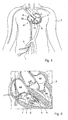
Fig. 1 schematically shows a catheter according to the invention with a first end in a heart ventricle; -
Fig. 2 schematically shows a number of catheters in a heart, for a treatment of cardiac arrhythmias; -
Fig. 3 schematically shows, greatly enlarged, in cross section, a forward end of a catheter according to the invention, in a first embodiment; -
Fig. 4 schematically shows, greatly enlarged, in cross section, a forward end of a catheter according to the invention, in a second embodiment; -
Fig. 5 schematically shows, greatly enlarged, in cross section, a forward end of a catheter according to the invention, in a third embodiment; and -
Fig. 5A shows a cross section along the line VA-VA inFig. 5 . - In this description, identical or corresponding parts have identical or corresponding reference numerals. The depicted embodiments are given only by way of example and should not be construed as being limitative in any manner. In particular, combinations of parts of the embodiments shown are also understood to be described herein. A body cavity is understood herein to include at least each part of a human or animal body which can be reached by a forward end of a catheter.
- In
Fig. 1 it is schematically shown how acatheter 1 has been inserted into aheart 2 of apatient 3. Aforward end 4 of acatheter 1A is inserted into aventricle 5, in particular a right ventricle of the heart, while the corresponding forward end 4 of asecond catheter 1B is inserted into theright atrium 6 of theheart 2. This is merely shown as an illustration of possible positions. The catheter(s) is or are inserted into theheart 2 from, for instance, the groin of thepatient 3, which is a known method and will therefore not be described further; the known method and device for controlling these catheters and the mechanisms thereto in the catheter also will not be described. - In
Fig. 2 , aheart 2 is shown in cross section with the left andright ventricle right atrium catheters 1 have been inserted into thisheart 2. During, for instance, a measurement and/or treatment of cardiac arrhythmias, one ormore catheters 1 can be inserted into theheart 2, in order to obtain a clear picture of the electric currents in the heart. Each of the depictedcatheters 1 has abody 7 which is elongated and can be guided through the vascular system of the patient. Thebody 7 has aforward end 4, hereinafter called thefirst end 4, which is inserted into theheart 2. In, or at least adjacent the first end, a number ofelectrodes 8 are provided in the form of metal rings, for instance three, which are separated from each other by electrically insulating material of the body and each can be connected with electronic equipment via a conductive wire through thebody 7, so that measurements can be carried out in a known manner, for instance an electrogram can be made. - The
first end 4 is further provided with atip 9 manufactured from an electrically conductive material such as metal, which tip can be connected via an electrically-conductive wire 10 (Figs. 3 -6) with said electronic equipment (not shown), with which current can be fed via thewire 10 into saidtip 9. During the measurement and/or the treatment, the patient lies on an electrically conductive sub-surface, for instance on a grounding plate (not shown). For performing the treatment, for instance an ablation, thetip 9 of thecatheter 1 is pressed against thewall 11 of theheart 2, so that a current will start to flow through saidwall 11. As a result of electrical resistance of the tissue of the wall, heat development will occur adjacent thetip 9, whereby tissue can be treated, in particular heart muscle cells can be killed, so that undesired conduction pathways in theheart 2 or undesired sources of arrhythmias can be blocked. This is a known treatment, called ablation, for preventing cardiac arrhythmias. For a further description of these techniques, reference is made to the publications and relevant manuals mentioned in the introduction. - It is known to use a cooling fluid in a
catheter 1 for use in, for instance, ablation techniques. This cooling fluid is brought through a channel in the catheter to the forward end of the catheter and from there, it is either introduced into the blood stream or returned through the catheter. The cooling fluid is thereby brought against the inside of the catheter into close contact with the to-be-cooled electrode, such as the tip of the catheter, in order to cool this electrode and thereby prevent deposition of proteins on the outside. Such a catheter is, for instance, described inEP 0 856 292 . However, such catheters have the disadvantage that the temperature of the respective electrode, such as the tip, no longer offers a good representation of the heat development in saidwall 11 and/or in the blood B around said electrode. - With a
catheter 1 according to the invention, these disadvantages have been solved in that, during use, said electrode such as thetip 9 is not cooled, at least not directly, but rather the blood B is, so that no coagulation occurs and clots are prevented. As a result, the temperature of the respective electrode, such as thetip 9, can be accurately measured and controlled, while an estimate of the temperature of thewall 11 can be accurately made from it. - Hereinafter, a number of examples of
catheters 1 according to the invention will be described. - In
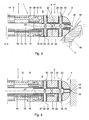
Fig. 3 , a first embodiment of a forward end of acatheter 1 according to the invention is shown, in cross-sectional side view. - This
catheter 1 comprises anelongated body 7 with afirst end 4, formed by atip 9 made of an electrically and thermally conductive material, in particular metal such as platinum. The body has a longitudinal axis A-A and comprises a substantiallycylindrical wall 12 through which achannel 13 extends. Between thewall 12 and thechannel 13, there is anannular space 14 through which extends, for instance, the electricallyconductive wire 10, the different connecting points for theelectrodes 8 and known control means (not shown) for controlling theend 4. Moreover, a second electrically-conductive wire 15 extends through theannular space 14, whichwire 15 is connected to athermocouple 16. - In the embodiment shown in
Fig. 3 , thetip 9 is coupled to thebody 7 by means of acoupling part 18 which is attached, for instance glued, to a first side inside thewall 12, and, on the other side, is fitted in a compatiblesecond snap edge 20 of thetip 9 via asnap edge 19. In this embodiment, thethermocouple 16 is arranged in or against theinterface 17 between thebody 7 and thetip 9, at least on theend surface 21 of thetip 9 proximal to thebody 7 and thecoupling part 18. - In the
first end 4, in particular in thetip 9, achannel part 22 is provided extending in line with the axis A-A and is connected to thechannel 13, for instance because asleeve 23 extends from saidend surface 21 in thechannel 13 and is fitted therein. From anexterior 41 of thetip 9, first bores 24 are provided reaching into thechannel part 22 and extending substantially radially. These first bores 24 all have alongitudinal axis 25 forming an angle α with the longitudinal axis A-A of thebody 7, for instance approximately 90°. Asecond bore 26 is provided in line with thechannel 13, at least with the axis A-A, which bore 26 terminates in the apex 36 of thetip 9. In each bore 24, 26, as well as around thechannel part 22, a thermal insulatingcasing 27 is provided, such that during use a cooling fluid, in particular a physiological saline solution, can be passed through thechannel 13, thechannel part 22 and thebores tip 9. Direct cooling of thetip 9 by the cooling fluid is thereby prevented in large part. In the embodiment ofFig. 3 , thesleeve 23 is not thermally insulated. - In
Fig. 4 , a first, more advantageous alternative embodiment of afirst end 4 of acatheter 1 according to the invention is shown, distinguished from the one according toFig. 3 in that herein, thesleeve 23 is also thermally insulated, while thethermocouple 16 is also arranged closer to the apex 36 of thetip 9, whereby an even more accurate temperature measurement of, in particular, the heart wall can be performed. - In
Fig. 5 , a further alternative embodiment is shown, withonly tip 9 in cross-sectional side view, which largely corresponds in a constructional sense to the embodiments ofFigs. 3 and 4 . However, atip 9 is provided herein that has a core 28, which is manufactured from a material having a low thermal and/or electrical conductivity, for instance glass, ceramic or plastic, and acasing 29 having good heat conductivity and/or electrical conductivity relative thereto. Herein, thebores casing 29, at least formed as part of the core 28, whereby the desired thermal insulation is obtained in a simple manner. In this embodiment, thelongitudinal axes 25 extend approximately tangentially relative to the channel part 22 (Fig. 5A ) and form an angle α with the longitudinal axis A-A, which angle deviates from 90°, for instance approximately 75° to 80°, such that the outflow direction is somewhat in the direction of the apex 36, at least in the direction of thewall 11. Thereby, the cooling of the blood around thetip 9 and adjacent thewall 11 can be improved even more. Athermocouple 16 is attached to thecasing 29. - In the embodiments according to the
Figs. 3-5 , the end of each bore 24, 26 always forms anoutflow opening 30 for cooling fluid. Theseoutflow openings 30 can for instance be formed such that during use a turbulent flow is generated in the blood flowing by. Means that can be used therefor are known from fluid dynamics. For instance, thirteen outflow openings are provided in the depicted embodiments, but it will be clear that any desired number ofoutflow openings 30 can be provided. - Optionally, one or more outlet openings can be provided near the electrode, in particular near the
interface 17 between thebody 7 and thetip 9, so that a part of the cooling fluid is directed along thetip 9, at least along the outer surface of the electrode, for direct cooling of the blood and/or for generating turbulence. - When using a
catheter 1 according to the invention in a treatment of, for instance, cardiac arrhythmias or the like, wherein an ablation technique is used in a body cavity, in which blood is flowing through, such as a ventricle or atrium of a heart or an artery or a vein, the current intensity and the supply of cooling fluid are preferably regulated such that the temperature of the blood around thetip 9 is kept below the coagulation temperature. In practice, this means below approximately 55°C, so that no coagulation occurs. Preferably, the temperature of thetip 9 is regulated such that it does not exceed 65°C. In practice, this has appeared to be a reasonably safe limit. With larger electrodes (of a length of, for instance, 8 mm instead of 4 mm), the flowing blood will provide proportionally more cooling so that there is a greater difference between the tissue and electrode temperature. With an 8 mm tip, 50 to 55° is a good target value, at least with existing electrodes. The electrode will clearly remain cooler than the heated tissue of the wall, which is kept below 100°C in order to prevent the earlier-mentioned explosions. InFig. 3 , anarea 40 is schematically indicated in thewall 11 wherein heat development occurs as a result of the current passed through thewall 11, as described earlier. Naturally, as to dimension and shape, this influencedarea 40 depends on the current intensity used and the duration of the treatment and is only given as an indication. - The invention is not limited in any manner to the exemplary embodiments given in the description and the drawing. Many variations thereon are possible within the framework of the invention as outlined by the claims.
- For instance, different materials can be used for the different parts, and outflow openings can be provided in different manners, as long as the
tip 9 is at least substantially prevented from being cooled from the inside by cooling fluid flowing therethrough. The leading end of the catheter can have any desired shape and can also be used at different locations than in the heart, for instance also for fighting tumors and such aberrations or for targeted creation of scar tissue. A catheter according to the invention can also be provided with several electrodes, at least one of which being provided with a cooling device according to the invention, with insulated outflow openings. Also, only one electrode can be provided at a distance from the end. - These and many comparable variations are understood to fall within the framework of the invention as outlined by the claims.
Claims (13)
- A catheter (1) comprisingan elongated body (7) coupled to an electrically-conductive first end (4) formed by a tip (9) and forming an electrode (9; 29);at least one current-carrying wire (10) extending through said body, which wire is electrically-connected to said electrode,a channel (13, 22) extending through said body and the first end and being adapted to supply a cooling fluid, at least one outlet opening (30) of the channel being provided in or near said first end anda temperature sensor (16) arranged in said first end or at an interface (17) between the body (7) and the tip (9),characterized in that:said channel (13, 22) is thermally insulated from the electrode (9; 29).
- The catheter (1) according to claim 1, wherein said at least one outlet opening is provided in said first end (4).
- The catheter (1) according to claim 1 or 2, wherein said channel (13) has a longitudinal direction (A-A) and said at least one outlet opening (30) comprises a series of outlet openings, which outlet openings are arranged such that, during use, cooling fluid supplied through said channel flows out through said outlet openings in an outflow direction which forms an angle (α) with said longitudinal direction.
- The catheter (1) according to claim 3, wherein said angle (α) is between 30° and 90°, more preferably between 45° and 90° and most preferably between 75° and 80°.
- The catheter according to any preceding claim, wherein the outlet opening(s) (30) is/are provided with a thermally insulating inner casing (27).
- The catheter (1) according to any one of claims 1 to 4, wherein the first end (4) includes:a core (28) manufactured from a material having low thermal conductivity and/or low electrical conductivity anda casing (29) having a good heat conductivity and/or good electrical conductivity relative to the core.
- The catheter (1) according to claim 6, wherein the core (28) is made of plastic, ceramic or glass and the casing (29) is made of metal.
- The catheter (1) according to claim 6 or 7, wherein the temperature sensor (16) is a thermocouple attached to the casing (29).
- The catheter (1) according to any preceding claim, wherein at least one said outlet opening (30) is provided in said body (7) adjacent said first end (4).
- The catheter (1) according to any preceding claim, wherein said first end (4) is attached to said body (7), and said temperature sensor (16) is provided in said first end at a distance from an interface (17) formed between said body and said first end.
- The catheter (1) according to any preceding claim, wherein the outlet opening(s) (30) is/are formed such that cooling fluid flowing therefrom during use flows away from said first end (4).
- The catheter (1) according to any preceding claim, wherein said first end (4) has at least one metal exterior (9; 29).
- The catheter (1) according to any preceding claim, wherein the outlet opening(s) (30) is/are formed such and/or is/are directed such that cooling fluid is directed along the tip (6), such that turbulence is generated around the first end (4) when cooling fluid flows therethrough.
Applications Claiming Priority (2)
| Application Number | Priority Date | Filing Date | Title |
|---|---|---|---|
| NL1024658A NL1024658C2 (en) | 2003-10-29 | 2003-10-29 | Catheter and method, in particular for ablation and the like. |
| PCT/NL2004/000741 WO2005048858A1 (en) | 2003-10-29 | 2004-10-20 | Catheter and method, in particular for ablation and like technique |
Publications (2)
| Publication Number | Publication Date |
|---|---|
| EP1686908A1 EP1686908A1 (en) | 2006-08-09 |
| EP1686908B1 true EP1686908B1 (en) | 2014-12-03 |
Family
ID=34617593
Family Applications (1)
| Application Number | Title | Priority Date | Filing Date |
|---|---|---|---|
| EP04793666.1A Not-in-force EP1686908B1 (en) | 2003-10-29 | 2004-10-20 | Catheter, in particular for ablation and like techniques |
Country Status (11)
| Country | Link |
|---|---|
| US (3) | US7815635B2 (en) |
| EP (1) | EP1686908B1 (en) |
| JP (1) | JP4776542B2 (en) |
| KR (1) | KR101218957B1 (en) |
| CN (1) | CN100586393C (en) |
| AU (1) | AU2004290563B2 (en) |
| BR (1) | BRPI0415696B8 (en) |
| CA (1) | CA2543524C (en) |
| NL (1) | NL1024658C2 (en) |
| RU (1) | RU2006118345A (en) |
| WO (1) | WO2005048858A1 (en) |
Families Citing this family (100)
| Publication number | Priority date | Publication date | Assignee | Title |
|---|---|---|---|---|
| ATE506891T1 (en) | 2002-08-24 | 2011-05-15 | St Jude Medical Atrial Fibrill | METHOD AND DEVICE FOR LOCALIZING THE FOSSA OVALIS AND PERFORMING A TRANSSEPTAL PUNCTURE |
| NL1024658C2 (en) | 2003-10-29 | 2005-05-02 | Univ Medisch Centrum Utrecht | Catheter and method, in particular for ablation and the like. |
| US8128621B2 (en) * | 2005-05-16 | 2012-03-06 | St. Jude Medical, Atrial Fibrillation Division, Inc. | Irrigated ablation electrode assembly and method for control of temperature |
| US7857810B2 (en) | 2006-05-16 | 2010-12-28 | St. Jude Medical, Atrial Fibrillation Division, Inc. | Ablation electrode assembly and methods for improved control of temperature and minimization of coagulation and tissue damage |
| US20080091193A1 (en) * | 2005-05-16 | 2008-04-17 | James Kauphusman | Irrigated ablation catheter having magnetic tip for magnetic field control and guidance |
| WO2007019876A1 (en) * | 2005-08-19 | 2007-02-22 | De Neve Werner Francois | Device and method for assisting heat ablation treatment of the heart |
| US8551085B2 (en) | 2006-10-10 | 2013-10-08 | St. Jude Medical, Atrial Fibrillation Division, Inc. | Ablation electrode assembly with insulated distal outlet |
| US8690870B2 (en) | 2006-12-28 | 2014-04-08 | St. Jude Medical, Atrial Fibrillation Division, Inc. | Irrigated ablation catheter system with pulsatile flow to prevent thrombus |
| US7824406B2 (en) | 2006-12-28 | 2010-11-02 | St. Jude Medical, Atrial Fibrillation Division, Inc. | Irrigated ablation catheter having a valve to prevent backflow |
| US7951143B2 (en) | 2006-12-28 | 2011-05-31 | St. Jude Medical, Artial Fibrillation Divsion, Inc. | Cooled ablation catheter with reciprocating flow |
| US7591816B2 (en) | 2006-12-28 | 2009-09-22 | St. Jude Medical, Atrial Fibrillation Division, Inc. | Irrigated ablation catheter having a pressure sensor to detect tissue contact |
| US7914528B2 (en) | 2006-12-29 | 2011-03-29 | St. Jude Medical, Atrial Fibrillation Division, Inc. | Ablation catheter tip for generating an angled flow |
| US8460285B2 (en) * | 2006-12-29 | 2013-06-11 | St. Jude Medical, Atrial Fibrillation Division, Inc. | Ablation catheter electrode having multiple thermal sensors and method of use |
| US8517999B2 (en) * | 2007-04-04 | 2013-08-27 | St. Jude Medical, Atrial Fibrillation Division, Inc. | Irrigated catheter with improved fluid flow |
| US8187267B2 (en) | 2007-05-23 | 2012-05-29 | St. Jude Medical, Atrial Fibrillation Division, Inc. | Ablation catheter with flexible tip and methods of making the same |
| US8764742B2 (en) | 2007-04-04 | 2014-07-01 | St. Jude Medical, Atrial Fibrillation Division, Inc. | Irrigated catheter |
| US8979837B2 (en) | 2007-04-04 | 2015-03-17 | St. Jude Medical, Atrial Fibrillation Division, Inc. | Flexible tip catheter with extended fluid lumen |
| US8974454B2 (en) | 2009-12-31 | 2015-03-10 | St. Jude Medical, Atrial Fibrillation Division, Inc. | Kit for non-invasive electrophysiology procedures and method of its use |
| US10220187B2 (en) | 2010-06-16 | 2019-03-05 | St. Jude Medical, Llc | Ablation catheter having flexible tip with multiple flexible electrode segments |
| US11395694B2 (en) | 2009-05-07 | 2022-07-26 | St. Jude Medical, Llc | Irrigated ablation catheter with multiple segmented ablation electrodes |
| US8734440B2 (en) | 2007-07-03 | 2014-05-27 | St. Jude Medical, Atrial Fibrillation Division, Inc. | Magnetically guided catheter |
| WO2009023385A1 (en) | 2007-07-03 | 2009-02-19 | Irvine Biomedical, Inc. | Magnetically guided catheter with flexible tip |
| US8128620B2 (en) | 2007-11-13 | 2012-03-06 | St. Jude Medical, Atrial Fibrillation Division, Inc. | Irrigated ablation electrode having proximal direction flow |
| US9579148B2 (en) | 2007-11-13 | 2017-02-28 | St. Jude Medical, Atrial Fibrillation Division, Inc. | Irrigated ablation electrode having recessed surface portions |
| US8052684B2 (en) | 2007-11-30 | 2011-11-08 | St. Jude Medical, Atrial Fibrillation Division, Inc. | Irrigated ablation catheter having parallel external flow and proximally tapered electrode |
| US8216225B2 (en) | 2007-12-21 | 2012-07-10 | St. Jude Medical, Atrial Fibrillation Division, Inc. | Irrigated ablation electrode assembly having a polygonal electrode |
| US8221409B2 (en) | 2007-12-21 | 2012-07-17 | St. Jude Medical, Atrial Fibrillation Division, Inc. | Thermally insulated irrigation catheter assembly |
| US8226641B2 (en) | 2007-12-21 | 2012-07-24 | St. Jude Medical, Atrial Fibrillation Division, Inc. | Medical catheter with deflection pull ring and distal tip attachment apparatus |
| US8273082B2 (en) | 2007-12-21 | 2012-09-25 | St. Jude Medical, Atrial Fibrillation Division, Inc. | Irrigated ablation catheter assembly having a flow member to create parallel external flow |
| US8882761B2 (en) * | 2008-07-15 | 2014-11-11 | Catheffects, Inc. | Catheter and method for improved ablation |
| US9675411B2 (en) * | 2008-07-15 | 2017-06-13 | Biosense Webster, Inc. | Catheter with perforated tip |
| US8974453B2 (en) | 2008-12-02 | 2015-03-10 | St. Jude Medical, Atrial Fibrillation Division, Inc. | Irrigated ablation catheter having a flexible manifold |
| US9757189B2 (en) * | 2008-12-03 | 2017-09-12 | Biosense Webster, Inc. | Prevention of kinks in catheter irrigation tubes |
| EP2373370A4 (en) * | 2008-12-05 | 2012-04-25 | Cathrx Ltd | An irrigation catheter and a method of fabricating |
| US9629678B2 (en) | 2008-12-30 | 2017-04-25 | St. Jude Medical, Atrial Fibrillation Division, Inc. | Controlled irrigated catheter ablation systems and methods thereof |
| US8475450B2 (en) * | 2008-12-30 | 2013-07-02 | Biosense Webster, Inc. | Dual-purpose lasso catheter with irrigation |
| US8864757B2 (en) * | 2008-12-31 | 2014-10-21 | St. Jude Medical, Atrial Fibrillation Division, Inc. | System and method for measuring force and torque applied to a catheter electrode tip |
| US10105177B2 (en) * | 2008-12-31 | 2018-10-23 | St. Jude Medical, Atrial Fibrillation Division, Inc. | Irrigated ablation electrode assembly having off-center irrigation passageway |
| US8926605B2 (en) | 2012-02-07 | 2015-01-06 | Advanced Cardiac Therapeutics, Inc. | Systems and methods for radiometrically measuring temperature during tissue ablation |
| US9277961B2 (en) | 2009-06-12 | 2016-03-08 | Advanced Cardiac Therapeutics, Inc. | Systems and methods of radiometrically determining a hot-spot temperature of tissue being treated |
| US8954161B2 (en) | 2012-06-01 | 2015-02-10 | Advanced Cardiac Therapeutics, Inc. | Systems and methods for radiometrically measuring temperature and detecting tissue contact prior to and during tissue ablation |
| US9226791B2 (en) | 2012-03-12 | 2016-01-05 | Advanced Cardiac Therapeutics, Inc. | Systems for temperature-controlled ablation using radiometric feedback |
| EP2453821A1 (en) * | 2009-07-13 | 2012-05-23 | Boston Scientific Scimed, Inc. | Open-irrigated ablation catheter with turbulent flow |
| US8920415B2 (en) | 2009-12-16 | 2014-12-30 | Biosense Webster (Israel) Ltd. | Catheter with helical electrode |
| US9616199B2 (en) * | 2009-12-31 | 2017-04-11 | St. Jude Medical, Atrial Fibrillation Division, Inc. | Irrigated catheter employing multi-lumenal irrigation tubing |
| US9949791B2 (en) | 2010-04-26 | 2018-04-24 | Biosense Webster, Inc. | Irrigated catheter with internal position sensor |
| US9510894B2 (en) | 2010-04-28 | 2016-12-06 | Biosense Webster (Israel) Ltd. | Irrigated ablation catheter having irrigation ports with reduced hydraulic resistance |
| US9943362B2 (en) * | 2010-04-28 | 2018-04-17 | Biosense Webster, Inc. | Irrigated ablation catheter with improved fluid flow |
| US9943363B2 (en) * | 2010-04-28 | 2018-04-17 | Biosense Webster, Inc. | Irrigated ablation catheter with improved fluid flow |
| CN105396215A (en) | 2010-08-13 | 2016-03-16 | 导管治疗有限公司 | A Catheter Sheath And A Method Of Manufacturing |
| US10016233B2 (en) * | 2010-12-06 | 2018-07-10 | Biosense Webster (Israel) Ltd. | Treatment of atrial fibrillation using high-frequency pacing and ablation of renal nerves |
| US8814857B2 (en) * | 2010-12-17 | 2014-08-26 | St. Jude Medical, Atrial Filbrillation Division, Inc. | Irrigated ablation electrode assemblies |
| US9788891B2 (en) | 2010-12-28 | 2017-10-17 | St. Jude Medical, Atrial Fibrillation Division, Inc. | Ablation electrode assemblies and methods for using same |
| US8979840B2 (en) | 2010-12-17 | 2015-03-17 | St. Jude Medical, Atrial Fibrillation Division, Inc. | Irrigant distribution system for flexible electrodes |
| US9855094B2 (en) | 2010-12-28 | 2018-01-02 | St. Jude Medical, Atrial Fibrillation Division, Inc. | Multi-rate fluid flow and variable power delivery for ablation electrode assemblies used in catheter ablation procedures |
| CN103764056B (en) | 2011-04-12 | 2017-02-08 | 热医学公司 | Devices and methods for shaping therapy in fluid enhanced ablation |
| WO2012173673A1 (en) * | 2011-06-16 | 2012-12-20 | St. Jude Medical, Atrial Fibrillation Division, Inc. | Irrigant distribution system for flexible electrodes |
| US8956353B2 (en) * | 2011-12-29 | 2015-02-17 | Biosense Webster (Israel) Ltd. | Electrode irrigation using micro-jets |
| CN103284786B (en) * | 2012-02-29 | 2015-11-11 | 四川锦江电子科技有限公司 | The perfusion electrophysiologicalcatheter catheter of controllable bidirectional deflection |
| CN103315808A (en) * | 2012-03-23 | 2013-09-25 | 心诺普医疗技术(北京)有限公司 | Ablation electrode and injection type electrode conduit adopting same |
| CN102631240A (en) * | 2012-04-13 | 2012-08-15 | 上海微创电生理医疗科技有限公司 | Cold brine infusion type radiofrequency ablation catheter |
| US9861738B2 (en) | 2012-05-07 | 2018-01-09 | St. Jude Medical, Cardiology Division, Inc. | Flex tip fluid lumen assembly with termination tube |
| US10004877B2 (en) | 2012-05-07 | 2018-06-26 | St. Jude Medical, Atrial Fibrillation Division, Inc. | Deflectable catheter shaft section, catheter incorporating same, and method of manufacturing same |
| US10022176B2 (en) | 2012-08-15 | 2018-07-17 | Thermedical, Inc. | Low profile fluid enhanced ablation therapy devices and methods |
| US9066725B2 (en) * | 2012-12-06 | 2015-06-30 | St. Jude Medical, Atrial Fibrillation Division, Inc. | Irrigant distribution system for electrodes |
| US9050010B2 (en) | 2012-12-31 | 2015-06-09 | Biosense Webster (Israel) Ltd. | Double loop lasso with single puller wire for bi-directional actuation |
| ITPD20130020A1 (en) * | 2013-01-30 | 2014-07-31 | Gioachino Coppi | VARIABLE BEND CATHETER |
| US9610396B2 (en) | 2013-03-15 | 2017-04-04 | Thermedical, Inc. | Systems and methods for visualizing fluid enhanced ablation therapy |
| US9033972B2 (en) | 2013-03-15 | 2015-05-19 | Thermedical, Inc. | Methods and devices for fluid enhanced microwave ablation therapy |
| GB201308901D0 (en) * | 2013-05-17 | 2013-07-03 | Gyrus Medical Ltd | Electrosurgical instrument and system |
| GB2515493A (en) * | 2013-06-24 | 2014-12-31 | Gyrus Medical Ltd | Electrosurgical instrument |
| EP3892222B1 (en) * | 2013-10-28 | 2024-02-07 | St. Jude Medical, Cardiology Division, Inc. | Ablation catheter designs |
| CN107693112A (en) * | 2013-11-15 | 2018-02-16 | 上海微创电生理医疗科技股份有限公司 | Ablating electrode and the catheter with the ablating electrode |
| DE102014201859A1 (en) * | 2014-02-03 | 2015-08-06 | Olympus Winter & Ibe Gmbh | Electrosurgical instrument |
| CN103876826A (en) * | 2014-03-12 | 2014-06-25 | 张文伟 | Hemorrhoid excision device |
| JP6618523B2 (en) | 2014-04-01 | 2019-12-18 | イノベーションズ イン メディスン,エルエルシー | Method for making and using a temperature responsive irrigated ablation electrode with reduced coolant flow |
| CA2967824A1 (en) | 2014-11-19 | 2016-05-26 | Advanced Cardiac Therapeutics, Inc. | Ablation devices, systems and methods of using a high-resolution electrode assembly |
| WO2016081611A1 (en) | 2014-11-19 | 2016-05-26 | Advanced Cardiac Therapeutics, Inc. | High-resolution mapping of tissue with pacing |
| JP6825789B2 (en) | 2014-11-19 | 2021-02-03 | エピックス セラピューティクス,インコーポレイテッド | Systems and methods for high resolution mapping of tissues |
| US11064929B2 (en) * | 2014-12-31 | 2021-07-20 | St. Jude Medical, Cardiology Division, Inc. | Flexible electrode tip with halo irrigation |
| US9636164B2 (en) | 2015-03-25 | 2017-05-02 | Advanced Cardiac Therapeutics, Inc. | Contact sensing systems and methods |
| JP6622817B2 (en) | 2015-03-31 | 2019-12-18 | セント・ジュード・メディカル,カーディオロジー・ディヴィジョン,インコーポレイテッド | Method and device for delivering pulsed RF energy during catheter ablation |
| CN104825226A (en) * | 2015-05-04 | 2015-08-12 | 中国人民解放军总医院 | Large ablation head and ablation device |
| WO2017160808A1 (en) | 2016-03-15 | 2017-09-21 | Advanced Cardiac Therapeutics, Inc. | Improved devices, systems and methods for irrigated ablation |
| US20170273732A1 (en) * | 2016-03-24 | 2017-09-28 | Boston Scientific Scimed Inc. | Regional flow sensor on cardiac catheter |
| US10105179B2 (en) | 2016-05-02 | 2018-10-23 | Affera, Inc. | Catheter sensing and irrigating |
| US9743984B1 (en) | 2016-08-11 | 2017-08-29 | Thermedical, Inc. | Devices and methods for delivering fluid to tissue during ablation therapy |
| WO2018067248A1 (en) * | 2016-10-04 | 2018-04-12 | St. Jude Medical, Cardiology Division, Inc. | Ablation catheter tip |
| EP3522807A1 (en) | 2016-10-04 | 2019-08-14 | Avent, Inc. | Cooled rf probes |
| CN110809448B (en) | 2017-04-27 | 2022-11-25 | Epix疗法公司 | Determining properties of contact between catheter tip and tissue |
| EP3687430A4 (en) | 2017-09-25 | 2021-09-01 | Sirona Medical Technologies, Inc. | Catheter and method for improved irrigation |
| WO2019071269A2 (en) | 2017-10-06 | 2019-04-11 | Powell Charles Lee | System and method to treat obstructive sleep apnea |
| US11083871B2 (en) | 2018-05-03 | 2021-08-10 | Thermedical, Inc. | Selectively deployable catheter ablation devices |
| US11918277B2 (en) | 2018-07-16 | 2024-03-05 | Thermedical, Inc. | Inferred maximum temperature monitoring for irrigated ablation therapy |
| JP7265014B2 (en) * | 2018-09-14 | 2023-04-25 | 杭州▲くん▼博生物科技有限公司 | High frequency ablation catheter, pulmonary high frequency ablation system, corresponding control method, control device and computer readable storage medium |
| US11471650B2 (en) | 2019-09-20 | 2022-10-18 | Biosense Webster (Israel) Ltd. | Mechanism for manipulating a puller wire |
| USD1014762S1 (en) | 2021-06-16 | 2024-02-13 | Affera, Inc. | Catheter tip with electrode panel(s) |
| CN114288007B (en) * | 2021-12-31 | 2022-09-30 | 心诺普医疗技术(北京)有限公司 | Fluid injection device and cryoballoon catheter |
| CN116458994B (en) * | 2023-06-12 | 2023-09-19 | 成都德倍佳医疗科技有限责任公司 | Fluid controllable type electrocoagulation electrode body, front end assembly, electrode and system thereof |
| CN116687553B (en) * | 2023-06-12 | 2023-10-10 | 成都德倍佳医疗科技有限责任公司 | Fluid controllable hemostatic front-end assembly, electrode and system thereof |
Family Cites Families (20)
| Publication number | Priority date | Publication date | Assignee | Title |
|---|---|---|---|---|
| US5098431A (en) * | 1989-04-13 | 1992-03-24 | Everest Medical Corporation | RF ablation catheter |
| US6641580B1 (en) * | 1993-11-08 | 2003-11-04 | Rita Medical Systems, Inc. | Infusion array ablation apparatus |
| US5462521A (en) * | 1993-12-21 | 1995-10-31 | Angeion Corporation | Fluid cooled and perfused tip for a catheter |
| JP3835703B2 (en) * | 1995-05-01 | 2006-10-18 | ボストン サイエンティフィック リミテッド | System for sensing subsurface temperature of body tissue during ablation with actively cooled electrodes |
| US6059780A (en) * | 1995-08-15 | 2000-05-09 | Rita Medical Systems, Inc. | Multiple antenna ablation apparatus and method with cooling element |
| AU702374B2 (en) * | 1995-08-18 | 1999-02-18 | Somnus Medical Technologies, Inc. | Method and apparatus for treatment of air way obstructions |
| US5913854A (en) | 1997-02-04 | 1999-06-22 | Medtronic, Inc. | Fluid cooled ablation catheter and method for making |
| US5843152A (en) * | 1997-06-02 | 1998-12-01 | Irvine Biomedical, Inc. | Catheter system having a ball electrode |
| US6869431B2 (en) | 1997-07-08 | 2005-03-22 | Atrionix, Inc. | Medical device with sensor cooperating with expandable member |
| US6049737A (en) * | 1998-05-05 | 2000-04-11 | Cardiac Pacemakers, Inc. | Catheter having common lead for electrode and sensor |
| US6740082B2 (en) | 1998-12-29 | 2004-05-25 | John H. Shadduck | Surgical instruments for treating gastro-esophageal reflux |
| US6123703A (en) | 1998-09-19 | 2000-09-26 | Tu; Lily Chen | Ablation catheter and methods for treating tissues |
| US6171275B1 (en) * | 1998-12-03 | 2001-01-09 | Cordis Webster, Inc. | Irrigated split tip electrode catheter |
| US6405078B1 (en) * | 1999-01-15 | 2002-06-11 | Biosense Webster, Inc. | Porous irrigated tip electrode catheter |
| US6466818B1 (en) * | 1999-01-15 | 2002-10-15 | Biosense Webster, Inc. | Porous irrigated tip electrode catheter |
| US6662034B2 (en) * | 2000-11-15 | 2003-12-09 | Stereotaxis, Inc. | Magnetically guidable electrophysiology catheter |
| US6611699B2 (en) * | 2001-06-28 | 2003-08-26 | Scimed Life Systems, Inc. | Catheter with an irrigated composite tip electrode |
| US6939350B2 (en) * | 2001-10-22 | 2005-09-06 | Boston Scientific Scimed, Inc. | Apparatus for supporting diagnostic and therapeutic elements in contact with tissue including electrode cooling device |
| US7311708B2 (en) * | 2001-12-12 | 2007-12-25 | Tissuelink Medical, Inc. | Fluid-assisted medical devices, systems and methods |
| NL1024658C2 (en) | 2003-10-29 | 2005-05-02 | Univ Medisch Centrum Utrecht | Catheter and method, in particular for ablation and the like. |
-
2003
- 2003-10-29 NL NL1024658A patent/NL1024658C2/en not_active IP Right Cessation
-
2004
- 2004-10-20 EP EP04793666.1A patent/EP1686908B1/en not_active Not-in-force
- 2004-10-20 CA CA2543524A patent/CA2543524C/en active Active
- 2004-10-20 BR BRPI0415696A patent/BRPI0415696B8/en not_active IP Right Cessation
- 2004-10-20 WO PCT/NL2004/000741 patent/WO2005048858A1/en active Application Filing
- 2004-10-20 AU AU2004290563A patent/AU2004290563B2/en not_active Ceased
- 2004-10-20 CN CN200480039067A patent/CN100586393C/en not_active Expired - Fee Related
- 2004-10-20 RU RU2006118345/14A patent/RU2006118345A/en not_active Application Discontinuation
- 2004-10-20 JP JP2006537907A patent/JP4776542B2/en not_active Expired - Fee Related
- 2004-10-20 US US10/595,608 patent/US7815635B2/en active Active
-
2006
- 2006-05-26 KR KR1020067010319A patent/KR101218957B1/en active IP Right Grant
-
2010
- 2010-10-08 US US12/900,983 patent/US7998141B2/en not_active Expired - Fee Related
-
2011
- 2011-08-15 US US13/210,090 patent/US8287533B2/en active Active
Also Published As
| Publication number | Publication date |
|---|---|
| JP4776542B2 (en) | 2011-09-21 |
| US7815635B2 (en) | 2010-10-19 |
| RU2006118345A (en) | 2007-12-10 |
| CA2543524C (en) | 2012-10-09 |
| BRPI0415696A (en) | 2006-12-26 |
| EP1686908A1 (en) | 2006-08-09 |
| BRPI0415696B1 (en) | 2018-04-03 |
| AU2004290563B2 (en) | 2010-09-23 |
| CN1897885A (en) | 2007-01-17 |
| JP2007509693A (en) | 2007-04-19 |
| BRPI0415696B8 (en) | 2021-06-22 |
| US20080045943A1 (en) | 2008-02-21 |
| US20110301596A1 (en) | 2011-12-08 |
| US7998141B2 (en) | 2011-08-16 |
| AU2004290563A1 (en) | 2005-06-02 |
| US8287533B2 (en) | 2012-10-16 |
| US20110022046A1 (en) | 2011-01-27 |
| CA2543524A1 (en) | 2005-06-02 |
| NL1024658C2 (en) | 2005-05-02 |
| CN100586393C (en) | 2010-02-03 |
| WO2005048858A1 (en) | 2005-06-02 |
| KR20060123207A (en) | 2006-12-01 |
| KR101218957B1 (en) | 2013-01-04 |
Similar Documents
| Publication | Publication Date | Title |
|---|---|---|
| EP1686908B1 (en) | Catheter, in particular for ablation and like techniques | |
| JP6716249B2 (en) | Catheter with irrigated tip electrode having porous substrate and high density surface microelectrodes | |
| EP1769763B1 (en) | System for creating lesions using bipolar electrodes | |
| US10813687B2 (en) | Cooled ablation catheter devices and methods of use | |
| CA2699675C (en) | Cooled ablation catheter devices and methods of use | |
| JP4242026B2 (en) | Split tip electrode catheter and signal processing RF ablation system | |
| AU2019280061B2 (en) | Irrigated electrodes with enhanced heat conduction | |
| US20110160726A1 (en) | Apparatus and methods for fluid cooled electrophysiology procedures | |
| CN103181820A (en) | Electrode irrigation using micro-jets | |
| EP3226757B1 (en) | System to assess quality of occlusion through impedance measurement | |
| CN109700522A (en) | Conduit with improved temperature-responsive | |
| EP3226749A1 (en) | Determination of pulmonary vein and other vascular occlusion using temperature profile following cold saline injection | |
| CN110087571A (en) | With the cooling open flushing ablation catheter of proximal end insertion piece | |
| US20240016538A1 (en) | Electrosurigcal Device and Methods | |
| CN104414738A (en) | Adaptive electrode for bi-polar ablation | |
| CN114098946A (en) | Proximal electrode cooling | |
| CN113116512A (en) | Ablation electrode assembly and ablation catheter |
Legal Events
| Date | Code | Title | Description |
|---|---|---|---|
| PUAI | Public reference made under article 153(3) epc to a published international application that has entered the european phase |
Free format text: ORIGINAL CODE: 0009012 |
|
| 17P | Request for examination filed |
Effective date: 20060523 |
|
| AK | Designated contracting states |
Kind code of ref document: A1 Designated state(s): AT BE BG CH CY CZ DE DK EE ES FI FR GB GR HU IE IT LI LU MC NL PL PT RO SE SI SK TR |
|
| DAX | Request for extension of the european patent (deleted) | ||
| 17Q | First examination report despatched |
Effective date: 20070614 |
|
| GRAP | Despatch of communication of intention to grant a patent |
Free format text: ORIGINAL CODE: EPIDOSNIGR1 |
|
| INTG | Intention to grant announced |
Effective date: 20140710 |
|
| RIN1 | Information on inventor provided before grant (corrected) |
Inventor name: NAKAGAWA, HIROSHI Inventor name: WITTKAMPF, FREDERIK HENRICUS MATHEUS |
|
| GRAS | Grant fee paid |
Free format text: ORIGINAL CODE: EPIDOSNIGR3 |
|
| GRAA | (expected) grant |
Free format text: ORIGINAL CODE: 0009210 |
|
| AK | Designated contracting states |
Kind code of ref document: B1 Designated state(s): AT BE BG CH CY CZ DE DK EE ES FI FR GB GR HU IE IT LI LU MC NL PL PT RO SE SI SK TR |
|
| REG | Reference to a national code |
Ref country code: GB Ref legal event code: FG4D |
|
| REG | Reference to a national code |
Ref country code: AT Ref legal event code: REF Ref document number: 698904 Country of ref document: AT Kind code of ref document: T Effective date: 20141215 Ref country code: CH Ref legal event code: EP |
|
| REG | Reference to a national code |
Ref country code: IE Ref legal event code: FG4D |
|
| REG | Reference to a national code |
Ref country code: DE Ref legal event code: R096 Ref document number: 602004046274 Country of ref document: DE Effective date: 20150115 |
|
| REG | Reference to a national code |
Ref country code: NL Ref legal event code: VDEP Effective date: 20141203 |
|
| REG | Reference to a national code |
Ref country code: AT Ref legal event code: MK05 Ref document number: 698904 Country of ref document: AT Kind code of ref document: T Effective date: 20141203 |
|
| PG25 | Lapsed in a contracting state [announced via postgrant information from national office to epo] |
Ref country code: ES Free format text: LAPSE BECAUSE OF FAILURE TO SUBMIT A TRANSLATION OF THE DESCRIPTION OR TO PAY THE FEE WITHIN THE PRESCRIBED TIME-LIMIT Effective date: 20141203 Ref country code: NL Free format text: LAPSE BECAUSE OF FAILURE TO SUBMIT A TRANSLATION OF THE DESCRIPTION OR TO PAY THE FEE WITHIN THE PRESCRIBED TIME-LIMIT Effective date: 20141203 Ref country code: FI Free format text: LAPSE BECAUSE OF FAILURE TO SUBMIT A TRANSLATION OF THE DESCRIPTION OR TO PAY THE FEE WITHIN THE PRESCRIBED TIME-LIMIT Effective date: 20141203 |
|
| PG25 | Lapsed in a contracting state [announced via postgrant information from national office to epo] |
Ref country code: GR Free format text: LAPSE BECAUSE OF FAILURE TO SUBMIT A TRANSLATION OF THE DESCRIPTION OR TO PAY THE FEE WITHIN THE PRESCRIBED TIME-LIMIT Effective date: 20150304 Ref country code: CY Free format text: LAPSE BECAUSE OF FAILURE TO SUBMIT A TRANSLATION OF THE DESCRIPTION OR TO PAY THE FEE WITHIN THE PRESCRIBED TIME-LIMIT Effective date: 20141203 Ref country code: AT Free format text: LAPSE BECAUSE OF FAILURE TO SUBMIT A TRANSLATION OF THE DESCRIPTION OR TO PAY THE FEE WITHIN THE PRESCRIBED TIME-LIMIT Effective date: 20141203 Ref country code: SE Free format text: LAPSE BECAUSE OF FAILURE TO SUBMIT A TRANSLATION OF THE DESCRIPTION OR TO PAY THE FEE WITHIN THE PRESCRIBED TIME-LIMIT Effective date: 20141203 |
|
| PG25 | Lapsed in a contracting state [announced via postgrant information from national office to epo] |
Ref country code: RO Free format text: LAPSE BECAUSE OF FAILURE TO SUBMIT A TRANSLATION OF THE DESCRIPTION OR TO PAY THE FEE WITHIN THE PRESCRIBED TIME-LIMIT Effective date: 20141203 Ref country code: PT Free format text: LAPSE BECAUSE OF FAILURE TO SUBMIT A TRANSLATION OF THE DESCRIPTION OR TO PAY THE FEE WITHIN THE PRESCRIBED TIME-LIMIT Effective date: 20150403 Ref country code: EE Free format text: LAPSE BECAUSE OF FAILURE TO SUBMIT A TRANSLATION OF THE DESCRIPTION OR TO PAY THE FEE WITHIN THE PRESCRIBED TIME-LIMIT Effective date: 20141203 Ref country code: SK Free format text: LAPSE BECAUSE OF FAILURE TO SUBMIT A TRANSLATION OF THE DESCRIPTION OR TO PAY THE FEE WITHIN THE PRESCRIBED TIME-LIMIT Effective date: 20141203 Ref country code: CZ Free format text: LAPSE BECAUSE OF FAILURE TO SUBMIT A TRANSLATION OF THE DESCRIPTION OR TO PAY THE FEE WITHIN THE PRESCRIBED TIME-LIMIT Effective date: 20141203 |
|
| PG25 | Lapsed in a contracting state [announced via postgrant information from national office to epo] |
Ref country code: PL Free format text: LAPSE BECAUSE OF FAILURE TO SUBMIT A TRANSLATION OF THE DESCRIPTION OR TO PAY THE FEE WITHIN THE PRESCRIBED TIME-LIMIT Effective date: 20141203 |
|
| REG | Reference to a national code |
Ref country code: DE Ref legal event code: R097 Ref document number: 602004046274 Country of ref document: DE |
|
| PLBE | No opposition filed within time limit |
Free format text: ORIGINAL CODE: 0009261 |
|
| STAA | Information on the status of an ep patent application or granted ep patent |
Free format text: STATUS: NO OPPOSITION FILED WITHIN TIME LIMIT |
|
| REG | Reference to a national code |
Ref country code: FR Ref legal event code: PLFP Year of fee payment: 12 |
|
| PG25 | Lapsed in a contracting state [announced via postgrant information from national office to epo] |
Ref country code: DK Free format text: LAPSE BECAUSE OF FAILURE TO SUBMIT A TRANSLATION OF THE DESCRIPTION OR TO PAY THE FEE WITHIN THE PRESCRIBED TIME-LIMIT Effective date: 20141203 |
|
| 26N | No opposition filed |
Effective date: 20150904 |
|
| PG25 | Lapsed in a contracting state [announced via postgrant information from national office to epo] |
Ref country code: SI Free format text: LAPSE BECAUSE OF FAILURE TO SUBMIT A TRANSLATION OF THE DESCRIPTION OR TO PAY THE FEE WITHIN THE PRESCRIBED TIME-LIMIT Effective date: 20141203 |
|
| PG25 | Lapsed in a contracting state [announced via postgrant information from national office to epo] |
Ref country code: LU Free format text: LAPSE BECAUSE OF FAILURE TO SUBMIT A TRANSLATION OF THE DESCRIPTION OR TO PAY THE FEE WITHIN THE PRESCRIBED TIME-LIMIT Effective date: 20151020 Ref country code: BE Free format text: LAPSE BECAUSE OF FAILURE TO SUBMIT A TRANSLATION OF THE DESCRIPTION OR TO PAY THE FEE WITHIN THE PRESCRIBED TIME-LIMIT Effective date: 20141203 |
|
| REG | Reference to a national code |
Ref country code: CH Ref legal event code: PL |
|
| PG25 | Lapsed in a contracting state [announced via postgrant information from national office to epo] |
Ref country code: MC Free format text: LAPSE BECAUSE OF FAILURE TO SUBMIT A TRANSLATION OF THE DESCRIPTION OR TO PAY THE FEE WITHIN THE PRESCRIBED TIME-LIMIT Effective date: 20141203 |
|
| REG | Reference to a national code |
Ref country code: IE Ref legal event code: MM4A |
|
| PG25 | Lapsed in a contracting state [announced via postgrant information from national office to epo] |
Ref country code: LI Free format text: LAPSE BECAUSE OF NON-PAYMENT OF DUE FEES Effective date: 20151031 Ref country code: CH Free format text: LAPSE BECAUSE OF NON-PAYMENT OF DUE FEES Effective date: 20151031 |
|
| REG | Reference to a national code |
Ref country code: FR Ref legal event code: PLFP Year of fee payment: 13 |
|
| PG25 | Lapsed in a contracting state [announced via postgrant information from national office to epo] |
Ref country code: IE Free format text: LAPSE BECAUSE OF NON-PAYMENT OF DUE FEES Effective date: 20151020 |
|
| PG25 | Lapsed in a contracting state [announced via postgrant information from national office to epo] |
Ref country code: HU Free format text: LAPSE BECAUSE OF FAILURE TO SUBMIT A TRANSLATION OF THE DESCRIPTION OR TO PAY THE FEE WITHIN THE PRESCRIBED TIME-LIMIT; INVALID AB INITIO Effective date: 20041020 Ref country code: BG Free format text: LAPSE BECAUSE OF FAILURE TO SUBMIT A TRANSLATION OF THE DESCRIPTION OR TO PAY THE FEE WITHIN THE PRESCRIBED TIME-LIMIT Effective date: 20141203 |
|
| PG25 | Lapsed in a contracting state [announced via postgrant information from national office to epo] |
Ref country code: TR Free format text: LAPSE BECAUSE OF FAILURE TO SUBMIT A TRANSLATION OF THE DESCRIPTION OR TO PAY THE FEE WITHIN THE PRESCRIBED TIME-LIMIT Effective date: 20141203 |
|
| REG | Reference to a national code |
Ref country code: FR Ref legal event code: PLFP Year of fee payment: 14 |
|
| REG | Reference to a national code |
Ref country code: FR Ref legal event code: PLFP Year of fee payment: 15 |
|
| PGFP | Annual fee paid to national office [announced via postgrant information from national office to epo] |
Ref country code: FR Payment date: 20210921 Year of fee payment: 18 |
|
| PGFP | Annual fee paid to national office [announced via postgrant information from national office to epo] |
Ref country code: GB Payment date: 20210929 Year of fee payment: 18 |
|
| PGFP | Annual fee paid to national office [announced via postgrant information from national office to epo] |
Ref country code: DE Payment date: 20210916 Year of fee payment: 18 |
|
| PGFP | Annual fee paid to national office [announced via postgrant information from national office to epo] |
Ref country code: IT Payment date: 20211012 Year of fee payment: 18 |
|
| REG | Reference to a national code |
Ref country code: DE Ref legal event code: R119 Ref document number: 602004046274 Country of ref document: DE |
|
| GBPC | Gb: european patent ceased through non-payment of renewal fee |
Effective date: 20221020 |
|
| PG25 | Lapsed in a contracting state [announced via postgrant information from national office to epo] |
Ref country code: FR Free format text: LAPSE BECAUSE OF NON-PAYMENT OF DUE FEES Effective date: 20221031 Ref country code: DE Free format text: LAPSE BECAUSE OF NON-PAYMENT OF DUE FEES Effective date: 20230503 |
|
| PG25 | Lapsed in a contracting state [announced via postgrant information from national office to epo] |
Ref country code: IT Free format text: LAPSE BECAUSE OF NON-PAYMENT OF DUE FEES Effective date: 20221020 Ref country code: GB Free format text: LAPSE BECAUSE OF NON-PAYMENT OF DUE FEES Effective date: 20221020 |