EP1686776A1 - User hand detection for wireless devices - Google Patents
User hand detection for wireless devices Download PDFInfo
- Publication number
- EP1686776A1 EP1686776A1 EP05100621A EP05100621A EP1686776A1 EP 1686776 A1 EP1686776 A1 EP 1686776A1 EP 05100621 A EP05100621 A EP 05100621A EP 05100621 A EP05100621 A EP 05100621A EP 1686776 A1 EP1686776 A1 EP 1686776A1
- Authority
- EP
- European Patent Office
- Prior art keywords
- wireless device
- acceleration measurement
- accelerometer
- vibration motor
- acceleration
- Prior art date
- Legal status (The legal status is an assumption and is not a legal conclusion. Google has not performed a legal analysis and makes no representation as to the accuracy of the status listed.)
- Granted
Links
Images


Classifications
-
- H—ELECTRICITY
- H04—ELECTRIC COMMUNICATION TECHNIQUE
- H04M—TELEPHONIC COMMUNICATION
- H04M19/00—Current supply arrangements for telephone systems
- H04M19/02—Current supply arrangements for telephone systems providing ringing current or supervisory tones, e.g. dialling tone or busy tone
- H04M19/04—Current supply arrangements for telephone systems providing ringing current or supervisory tones, e.g. dialling tone or busy tone the ringing-current being generated at the substations
-
- H—ELECTRICITY
- H04—ELECTRIC COMMUNICATION TECHNIQUE
- H04M—TELEPHONIC COMMUNICATION
- H04M1/00—Substation equipment, e.g. for use by subscribers
- H04M1/72—Mobile telephones; Cordless telephones, i.e. devices for establishing wireless links to base stations without route selection
- H04M1/724—User interfaces specially adapted for cordless or mobile telephones
- H04M1/72448—User interfaces specially adapted for cordless or mobile telephones with means for adapting the functionality of the device according to specific conditions
- H04M1/72454—User interfaces specially adapted for cordless or mobile telephones with means for adapting the functionality of the device according to specific conditions according to context-related or environment-related conditions
-
- H—ELECTRICITY
- H04—ELECTRIC COMMUNICATION TECHNIQUE
- H04M—TELEPHONIC COMMUNICATION
- H04M19/00—Current supply arrangements for telephone systems
- H04M19/02—Current supply arrangements for telephone systems providing ringing current or supervisory tones, e.g. dialling tone or busy tone
- H04M19/04—Current supply arrangements for telephone systems providing ringing current or supervisory tones, e.g. dialling tone or busy tone the ringing-current being generated at the substations
- H04M19/047—Vibrating means for incoming calls
-
- H—ELECTRICITY
- H04—ELECTRIC COMMUNICATION TECHNIQUE
- H04M—TELEPHONIC COMMUNICATION
- H04M2250/00—Details of telephonic subscriber devices
- H04M2250/12—Details of telephonic subscriber devices including a sensor for measuring a physical value, e.g. temperature or motion
Definitions
- This invention relates to the field of user hand detection for wireless devices, and more specifically, to user hand detection for wireless devices using on-board accelerometers and vibration motors.
- Wireless mobile communication devices include microprocessors, memory, soundcards, and run one or more software applications. Examples of software applications used in these wireless devices include micro-browsers, address books, email clients, and wavetable instruments. Additionally, wireless devices have access to a plurality of services via the Internet.
- a wireless device may, for example, be used to browse web sites on the Internet, to transmit and receive graphics, and to execute streaming audio and/or video applications.
- the transfer of Internet content to and from wireless device is typically facilitated by the Wireless Application Protocol ("WAP"), which integrates the Internet and other networks with wireless network platforms.
- WAP Wireless Application Protocol
- Such wireless devices include, for example, the BlackBerry® handheld developed by Research In Motion Ltd.(RIM®).
- Wireless devices communicate with each other and over wireless networks.
- wireless networks are maintained by wireless carriers.
- a wireless carrier or wireless network operator typically owns and operates a wireless network including radio equipment, base stations, antennae, interface equipment, servers, associated landlines, etc.
- a carrier also manages basic billing and other back-end services needed to sell wireless services to subscribers.
- Each wireless network can be based one of several different wireless standards or technologies including Code-Division Multiple Access (“CDMA”), General Packet Radio Service (“GPRS”), Mobitex, and Motorola's Integrated Digital Enhanced Network (“iDEN”) and DataTACTM networks.
- CDMA Code-Division Multiple Access
- GPRS General Packet Radio Service
- Mobitex Mobitex
- iDEN Integrated Digital Enhanced Network
- DataTACTM DataTACTM
- present wireless devices cannot effectively determine the nature of their physical surroundings.
- present wireless devices cannot effectively determine if they are being held by users.
- a method for determining whether a wireless device is being held comprising: activating a vibration motor in the wireless device to vibrate the wireless device for a predetermined period; receiving at least one acceleration measurement from an accelerometer in the wireless device during the predetermined period; and, comparing the at least one acceleration measurement to at least one stored acceleration measurement, the at least one stored acceleration measurement corresponding to a held wireless device.
- the at least one acceleration measurement and the at least one stored acceleration measurement are an acceleration pattern and a stored acceleration pattern, respectively.
- the held wireless device is held by a user.
- the held wireless device is held by a holster.
- the method further includes adjusting a feature of the wireless device in response to the comparing.
- the feature is at least one of a ring tone, a display screen time-out, and a display screen illumination intensity.
- the vibration motor and the accelerometer are at least one vibration motor and at least one accelerometer, respectively.
- a method for controlling a feature of a wireless device comprising: determining whether the wireless device is being held by: activating a vibration motor in the wireless device to vibrate the wireless device for a predetermined period; receiving at least one acceleration measurement from an accelerometer in the wireless device during the predetermined period; and, comparing the at least one acceleration measurement to at least one stored acceleration measurement, the at least one stored acceleration measurement corresponding to a held wireless device; and, adjusting the feature in response to the determining.
- a wireless device comprising: a processor coupled to memory, a vibration motor, and an accelerometer and adapted for: determining whether the wireless device is held by: activating the vibration motor to vibrate the wireless device for a predetermined period; receiving at least one acceleration measurement from the accelerometer during the predetermined period; and, comparing the at least one acceleration measurement to at least one stored acceleration measurement, the at least one stored acceleration measurement corresponding to a held wireless device.
- a method for determining a restraining force on a wireless device comprising: activating a vibration motor in the wireless device to vibrate the wireless device for a predetermined period; receiving at least one acceleration measurement from an accelerometer in the wireless device during the predetermined period; and, comparing the at least one acceleration measurement to at least one stored acceleration measurement, the at least one stored acceleration measurement corresponding to the restraining force.
- an apparatus such as a wireless device, a method for adapting this device, a computer program product, as well as articles of manufacture such as a computer readable medium having program instructions recorded thereon for practising the method of the invention.
- FIG. 2 is a block diagram illustrating a memory of the wireless device of FIG. 1. in accordance with an embodiment of the invention
- FIG. 3 is a front view illustrating the wireless device of FIG. 1 in accordance with an embodiment of the invention.
- FIG. 4 is a flow chart illustrating operations of modules within a wireless device for determining whether the wireless device is being held (e.g., in a user's hand, etc.) in accordance with an embodiment of the invention.
- the following detailed description of the embodiments of the present invention does not limit the implementation of the invention to any particular computer programming language.
- the present invention may be implemented in any computer programming language provided that the operating system ("OS") provides the facilities that may support the requirements of the present invention.
- a preferred embodiment is implemented in the JAVATM computer programming language (or other computer programming languages such as C or C++). (JAVA and all JAVA-based trademarks are the trademarks of Sun Microsystems Corporation.) Any limitations presented would be a result of a particular type of operating system or computer programming language and would not be a limitation of the present invention.
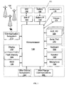
- FIG. 1 is a block diagram illustrating an exemplary wireless device 102 and wireless network 100 adapted in accordance with an embodiment of the invention.
- the wireless device 102 is a handheld device 102.
- the wireless network 100 includes antenna, base stations, and supporting radio equipment, known to those of ordinary skill in the art, for supporting wireless communications between the wireless device 102 and other wireless devices and systems (not shown).
- the wireless network 100 may be coupled to a wireless network gateway (not shown) and to a wide area network (not shown) to which the other systems (not shown) may be coupled through appropriate interfaces (not shown).
- the wireless device 102 is a two-way communication device having at least voice and advanced data communication capabilities, including the capability to communicate with other computer systems. Depending on the functionality provided by the device 102, it may be referred to as a data messaging device, a two-way pager, a cellular telephone with data messaging capabilities, a wireless Internet appliance, or a data communication device (with or without telephony capabilities).
- the device 102 may communicate with any one of a plurality of fixed transceiver stations 100 within its geographic coverage area.
- the wireless device 102 will normally incorporate a communication subsystem 111, which includes a RF receiver, a RF transmitter, and associated components, such as one or more (preferably embedded or internal) antenna elements and, local oscillators ("LOs"), and a processing module such as a digital signal processor (“DSP”) (all not shown).
- a communication subsystem 111 which includes a RF receiver, a RF transmitter, and associated components, such as one or more (preferably embedded or internal) antenna elements and, local oscillators (“LOs”), and a processing module such as a digital signal processor (“DSP”) (all not shown).
- LOs local oscillators
- DSP digital signal processor
- the device 102 is a battery-powered device so it also includes a battery IF 154 for receiving one or more rechargeable batteries 156. Such a battery 156 provides electrical power to most if not all electrical circuitry in the device 102, and the battery IF 154 provides for a mechanical and electrical connection for it.
- the battery IF 154 is coupled to a regulator (not shown) which provides power to the circuitry of the device 102.
- the wireless device 102 includes a microprocessor (or central processing system (“CPU”)) 138 which controls overall operation of the device 102. Communication functions, including at least data and voice communications, are performed through the communication subsystem 111.
- the microprocessor 138 also interacts with additional device subsystems such as a display 122, a flash memory 124 or other persistent store, a random access memory (“RAM”) 126, auxiliary input/output (“I/O") subsystems 128, a serial port 130, a keyboard 132, a speaker 134, a microphone 136, a short-range communications subsystem 140, and any other device subsystems generally designated at 142.
- additional device subsystems such as a display 122, a flash memory 124 or other persistent store, a random access memory (“RAM”) 126, auxiliary input/output (“I/O") subsystems 128, a serial port 130, a keyboard 132, a speaker 134, a microphone 136, a short-range communications subsystem 140, and any other
- Operating system software used by the microprocessor 138 is preferably stored in a persistent store such as the flash memory 124, which may alternatively be a read-only memory (“ROM”) or similar storage element (not shown).
- ROM read-only memory
- the microprocessor 138 in addition to its operating system functions, preferably enables execution of software applications on the device 102.
- a preferred application that may be loaded onto the device 102 may be a personal information manager (“PIM”) application having the ability to organize and manage data items relating to the user such as, but not limited to, instant messaging (“IM”), email, calendar events, voice mails, appointments, and task items.
- PIM personal information manager
- IM instant messaging
- SIM 162 to facilitate storage of PIM data items and other information.
- the PIM application preferably has the ability to send and receive data items via the wireless network 100.
- PIM data items are seamlessly integrated, synchronized, and updated via the wireless network 100, with the user's corresponding data items stored and/or associated with a host computer system (not shown) thereby creating a mirrored host computer on the device 102 with respect to such items. This is especially advantageous where the host computer system is the user's office computer system (not shown).
- Additional applications may also be loaded onto the device 102 through the network 100, an auxiliary I/O subsystem 128, serial port 130, short-range communications subsystem 140, or any other suitable subsystem 142, and installed by a user in RAM 126 or preferably in a non-volatile store (not shown) for execution by the microprocessor 138.
- Such flexibility in application installation increases the functionality of the device 102 and may provide enhanced on-device functions, communication-related functions, or both.
- secure communication applications may enable electronic commerce functions and other such financial transactions to be performed using the wireless device 102.
- a received signal such as a text message, an email message, or web page download will be processed by the communication subsystem 111 and input to the microprocessor 138.
- the microprocessor 138 will preferably further process the signal for output to the display 122 and/or to the auxiliary I/O device 128.
- a user of the wireless device 102 may also compose data items, such as email messages, for example, using the keyboard 132 in conjunction with the display 122 and possibly the auxiliary I/O device 128.
- the keyboard 132 is preferably a complete alphanumeric keyboard and/or telephone-type keypad. These composed items may be transmitted over a communication network 100 through the communication subsystem 111 or the short range communication subsystem 140.
- the overall operation of the wireless device 102 is substantially similar, except that the received signals would be output to the speaker 134 and signals for transmission would be generated by the microphone 136.
- Alternative voice or audio I/O subsystems such as a voice message recording subsystem, may also be implemented on the device 102.
- voice or audio signal output is preferably accomplished primarily through the speaker 134, the display 122 may also be used to provide, for example, an indication of the identity of a calling party, duration of a voice call, or other voice call related information.
- the serial port 130 shown in FIG. 2 is normally implemented in a personal digital assistant ("PDA")-type communication device for which synchronization with a user's desktop computer is a desirable, albeit optional, component.
- PDA personal digital assistant
- the serial port 130 enables a user to set preferences through an external device or software application and extends the capabilities of the device 102 by providing for information or software downloads to the device 102 other than through a wireless communication network 100.
- the alternate download path may, for example, be used to load an encryption key onto the device 102 through a direct and thus reliable and trusted connection to thereby provide secure device communication.
- the short-range communications subsystem 140 shown in FIG. 1 is an additional optional component which provides for communication between the device 102 and different systems or devices (not shown), which need not necessarily be similar devices.
- the subsystem 140 may include an infrared device and associated circuits and components, or a BluetoothTM communication module to provide for communication with similarly-enabled systems and devices.
- BluetoothTM is a registered trademark of Bluetooth SIG, Inc.
- the SIM card 162 is a small, stamp-sized "smart card” that is used in a Global System for Mobile Communications ("GSM") wireless device 102.
- GSM Global System for Mobile Communications
- the SIM contains a microchip that stores data that identifies the wireless device 102 to a carrier or service provider.
- the SIM also stores data used to encrypt voice and data transmissions, phone book information, etc.
- the SIM can be removed from a first wireless device and placed in a second wireless device. This enables the second wireless device to use information such as the subscriber's telephone and account numbers.
- the interface between a SIM and the wireless device 102 within a wireless network 100 is defined in European Telecommunications Standards Institute ("ETSI”) standard GSM 11.11 Version 6.2.0 Release 1997 ("Digital Cellular Telecommunications System (Phase 2+); Specification of the Subscriber Identity Module - Mobile Equipment (SIM - ME) Interface”), which is incorporated herein by reference.
- ETSI European Telecommunications Standards Institute
- GSM 11.11 Version 6.2.0 Release 1997 Digital Cellular Telecommunications System (Phase 2+); Specification of the Subscriber Identity Module - Mobile Equipment (SIM - ME) Interface
- MCC Mobile Country Code
- MNC Mobile Network Code
- IMSI International Mobile Subscriber Identity
- the wireless network 100 can include Code-Division Multiple Access (“CDMA”), General Packet Radio Service (“GPRS”), Mobitex, and Motorola's Integrated Digital Enhanced Network (“iDEN”) and DataTACTM networks.
- CDMA Code-Division Multiple Access
- GPRS General Packet Radio Service
- iDEN Integrated Digital
- FIG. 2 is a block diagram illustrating a memory 200 of the wireless device 102 of FIG. 1 in accordance with an embodiment of the invention.
- the memory 200 has various software components for controlling the device 102 and may include flash memory 124, RAM 126, or ROM (not shown), for example.
- the wireless device 102 is intended to be a multi-tasking wireless communications device configured for sending and receiving data items and for making and receiving voice calls.
- an operating system (“OS”) 202 resident on the device 102 provides a basic set of operations for supporting various applications typically operable through a graphical user interface (“GUI”) 204.
- GUI graphical user interface
- the OS 202 provides basic input/output system features to obtain input from the auxiliary I/O 128, keyboard 132, and the like, and for facilitating output to the user.
- software modules 206 for determining whether the wireless device is being held in a user's hand as will be described below.
- one or more applications for managing communications or for providing personal digital assistant like functions may also be included.
- the wireless device 102 includes computer executable programmed instructions for directing the device 102 to implement the embodiments of the present invention.
- the programmed instructions may be embodied in one or more software modules 206 resident in the memory 200 of the wireless device 102.
- the programmed instructions may be embodied on a computer readable medium (such as a CD disk or floppy disk) which may be used for transporting the programmed instructions to the memory 200 of the wireless device 102.
- the programmed instructions may be embedded in a computer-readable, signal-bearing medium that is uploaded to a network by a vendor or supplier of the programmed instructions, and this signal-bearing medium may be downloaded through an interface 111, 130, 140 to the wireless device 102 from the network by end users or potential buyers.
- FIG. 3 is a front view illustrating the wireless device 102 of FIG. 1 in accordance with an embodiment of the invention.
- the wireless device 102 can be a data and voice-enabled handheld device.
- the wireless device 102 includes a casing 150, a display screen 122, a graphical user interface ("GUI") 180, a keyboard (or keypad) 132, a thumbwheel (or trackwheel) 110, various select buttons 120, and various signal inputs/outputs 160 (e.g., power connector input, microphone, speaker, data interface input, etc.).
- GUI graphical user interface
- the wireless device 102 includes one or more circuit boards, a CPU 138, memory 200, a battery 156, an antenna, etc. (not shown) which are coupled to the signal inputs/outputs 160, keyboard 132, display screen 122, etc.
- the microprocessor 138 of the wireless device 102 is typically coupled to one or more devices 110, 120, 132 for receiving user commands or queries and for displaying the results of these commands or queries to the user on the display 122.
- user queries may be transformed into a combination of SQL commands for producing one or more tables of output data which may be incorporated in one or more display pages for presentation to the user.
- the microprocessor 138 is coupled to memory 200 for containing software modules 206 and data such as base tables or virtual tables such as views or derived tables.
- the memory 200 may include a variety of storage devices typically arranged in a hierarchy of storage as understood to those skilled in the art.
- GUIs are supported by common operating systems and provide a display format which enables a user to choose commands, execute application programs, manage computer files, and perform other functions by selecting pictorial representations known as icons, or items from a menu through use of an input or pointing device such as a thumbwheel 110 and keyboard 132.
- a GUI is used to convey information to and receive commands from users and generally includes a variety of GUI objects or controls, including icons, toolbars, drop-down menus, pop-up menus, text, dialog boxes, buttons, and the like.
- a user typically interacts with a GUI 180 presented on a display 122 by using an input or pointing device (e.g., a thumbwheel) 110 to position a pointer or cursor 190 over an object 191 (i.e., "pointing" at the object) and by "clicking" on the object 191. (e.g., by depressing the thumbwheel 110 or other button).
- an input or pointing device e.g., a thumbwheel
- a pointer or cursor 190 i.e., "pointing" at the object
- clicking on the object 191.
- the object 191 may be hilighted (e.g., shaded) when it is pointed at.
- a GUI based system presents application, system status, and other information to the user in "windows" appearing on the display 122.
- a window 192 is a more or less rectangular area within the display 122 in which a user may view an application or a document. Such a window 192 may be open, closed, displayed full screen, reduced to an icon, increased or reduced in size, or moved to different areas of the display 122. Multiple windows may be displayed simultaneously, such as: windows included within other windows, windows overlapping other windows, or windows tiled within the display area.
- the wireless device 102 includes an accelerometer 170 and a vibration motor or vibrator 175.
- Each of the accelerometer 170 and vibrator 175 are coupled to the microprocessor 138 either directly or through intermediary I/O circuitry 128.
- Each of the accelerometer 170 and vibrator 175 may include respective local controllers or drivers (not shown).
- the microprocessor 138 sends ON/OFF control messages to the vibrator 175 and reads output messages from the accelerometer 170.
- the accelerometer 170 may be a based on piezoelectric, piezioresistive, micromechanical capacitive, or micro-electrical mechanical systems ("MEMS") technology.
- MEMS accelerometer may be mounted on a circuit board within the wireless device 102.
- MEMS accelerometers may be based on bulk micromachined, surface micromachined, and thermal bulk/micromachined technology.
- a thermal-based MEMS accelerometer has no moving parts. Its principle of operation is based on differential thermal sensing of a heated gas inside a hermetic component. With no moving parts, such an accelerometer is capable of surviving the high shocks typically experienced by wireless devices, both in the field and during production.
- a single MEMS accelerometer can measure accelerations along two orthogonal axes.
- two MEMS accelerometers positioned orthogonal to each other can provide complete three axis motion information. While accelerometers output acceleration measurements and not position measurements, if position measurements are required these can be calculated by double integration of the acceleration measurements.
- the vibration motor or vibrator 175 typically includes a motor driver (not shown).
- the vibration motor may be a cylindrical motor or a pancake/coin motor as know to those of ordinary skill in the art of vibration motors for wireless devices.
- the vibration motor or vibrator 175 is any device capable of producing a vibration such as a piezoelectric vibration generation device.
- wireless devices 102 are given the means required to detect if they are being held by users. If a wireless device 102 is on a table or is in a user's pocket and is not being held by anyone, the accelerometer 170 can predictably measure the acceleration pattern that occurs when the vibrator 175 is turned on. Acceleration patterns differ when a wireless device 102 is being held by a person and when it is not being held.
- the acceleration patterns that are measured by the accelerometer 170 reflect the effective mass seen by the vibrator 175.
- the effective mass is greater as it includes the mass of the wireless device 102 and that of the user's hand and arm, etc.
- the wireless device 102 can determine if it is being held by turning on its vibrator 175 for a predetermined period of time and by reading the output of its accelerometer 170.
- the output of the accelerometer 170 may be combined with the outputs of other on-board sensors such as capacitive sensors or touchscreens, light sensors, strain gauges, etc., to determine further information concerning the surroundings of the wireless device 102.
- the microprocessor 138 of the wireless device 102 reads the output of the accelerometer 170 over the predetermined time period to generate an acceleration pattern. This acceleration pattern is then compared to one or more predetermined acceleration patterns that are stored in the memory 200 of the wireless device 102.
- the predetermined acceleration patterns include patterns corresponding to a held wireless device and a non-held wireless device. If the acceleration pattern corresponds to a predetermined acceleration pattern for a held wireless device, within a predetermined margin of error, then the microprocessor 138 determines that the wireless device 102 is being held by a user.
- the accelerometer 170 would measure a first acceleration pattern which the wireless device 102 could store in its memory 200.
- the accelerometer 170 would measure a second acceleration pattern which the wireless device could again store in its memory 200.
- the second acceleration pattern would have acceleration measurements having larger magnitudes than those of the first acceleration pattern.
- a wireless device 102 is able to determine information pertaining to its surrounding environment and adjust its operation accordingly. For example, if a wireless device 102 is aware that it is in its holster, it can shut off its display screen 122 in order to improve battery life. Similarly, it is advantageous for a wireless device 102 to know if it is being held in a user's hand. For example, if a wireless device 102 determines that it is in a user's hand, it can change its operational state or profile in response. In particular, the wireless device can vibrate upon receipt of message if it is in a user's hand and it could sound a ring tone if it is not in a user's hand.
- timeouts for the display screen 122 of the wireless device 102 can be set differently depending on whether the wireless device 102 is presently in a user's hand or not (e.g., a slower screen timeout can be used if the wireless device 102 is being held by a user).
- several predetermined acceleration patterns are stored in the memory 200 of the wireless device 102 for comparing to a currently measured acceleration pattern.
- the stored acceleration patterns may include patterns corresponding to a held wireless device (as described above), a non-held wireless device (as described above), a wireless device in its holster, a wireless device on a table, a wireless device in a pocket, etc.
- FIG. 4 is a flow chart illustrating operations 400 of modules 206 within a wireless device 102 for determining whether the wireless device 102 is being held (e.g., in a user's hand, etc.) in accordance with an embodiment of the invention.
- a vibration motor (or vibrator) 175 in the wireless device 102 is activated to vibrate the wireless device 102 for a predetermined period.
- At step 403 at least one acceleration measurement from an accelerometer 170 in the wireless device 102 is received during the predetermined period.
- the at least one acceleration measurement is compared to at least one stored acceleration measurement, the at least one stored acceleration measurement corresponding to a held wireless device.
- the at least one acceleration measurement and the at least one stored acceleration measurement are an acceleration pattern and a stored acceleration pattern, respectively.
- the held wireless device is held by a user.
- the held wireless device is held by a holster.
- the method further includes adjusting a feature of the wireless device 102 in response to the comparing.
- the feature is at least one of a ring tone 134, a display screen 122 time-out, and a display screen 122 illumination intensity.
- the vibration motor 175 and the accelerometer 170 are at least one vibration motor (e.g. multiple axes motors) and at least one accelerometer (e.g. multiple axes accelerometers), respectively.
Abstract
Description
- This invention relates to the field of user hand detection for wireless devices, and more specifically, to user hand detection for wireless devices using on-board accelerometers and vibration motors.
- Current wireless mobile communication devices include microprocessors, memory, soundcards, and run one or more software applications. Examples of software applications used in these wireless devices include micro-browsers, address books, email clients, and wavetable instruments. Additionally, wireless devices have access to a plurality of services via the Internet. A wireless device may, for example, be used to browse web sites on the Internet, to transmit and receive graphics, and to execute streaming audio and/or video applications. The transfer of Internet content to and from wireless device is typically facilitated by the Wireless Application Protocol ("WAP"), which integrates the Internet and other networks with wireless network platforms. Such wireless devices include, for example, the BlackBerry® handheld developed by Research In Motion Ltd.(RIM®).
- Wireless devices communicate with each other and over wireless networks. Typically, wireless networks are maintained by wireless carriers. A wireless carrier or wireless network operator typically owns and operates a wireless network including radio equipment, base stations, antennae, interface equipment, servers, associated landlines, etc. A carrier also manages basic billing and other back-end services needed to sell wireless services to subscribers. Each wireless network can be based one of several different wireless standards or technologies including Code-Division Multiple Access ("CDMA"), General Packet Radio Service ("GPRS"), Mobitex, and Motorola's Integrated Digital Enhanced Network ("iDEN") and DataTAC™ networks.
- However, one shortcoming of present wireless devices is that they cannot effectively determine the nature of their physical surroundings. In particular, present wireless devices cannot effectively determine if they are being held by users.
- A need therefore exists for an improved method and system for wireless devices to detect when they are being held by users. Accordingly, a solution that addresses, at least in part, the above and other shortcomings is desired.
- According to one aspect of the invention, there is provided a method for determining whether a wireless device is being held comprising: activating a vibration motor in the wireless device to vibrate the wireless device for a predetermined period; receiving at least one acceleration measurement from an accelerometer in the wireless device during the predetermined period; and, comparing the at least one acceleration measurement to at least one stored acceleration measurement, the at least one stored acceleration measurement corresponding to a held wireless device.
- Preferably, the at least one acceleration measurement and the at least one stored acceleration measurement are an acceleration pattern and a stored acceleration pattern, respectively.
- Preferably, the held wireless device is held by a user.
- Preferably, the held wireless device is held by a holster.
- Preferably, the method further includes adjusting a feature of the wireless device in response to the comparing.
- Preferably, the feature is at least one of a ring tone, a display screen time-out, and a display screen illumination intensity.
- Preferably, the vibration motor and the accelerometer are at least one vibration motor and at least one accelerometer, respectively.
- According to another aspect of the invention, there is provided a method for controlling a feature of a wireless device comprising: determining whether the wireless device is being held by: activating a vibration motor in the wireless device to vibrate the wireless device for a predetermined period; receiving at least one acceleration measurement from an accelerometer in the wireless device during the predetermined period; and, comparing the at least one acceleration measurement to at least one stored acceleration measurement, the at least one stored acceleration measurement corresponding to a held wireless device; and, adjusting the feature in response to the determining.
- According to another aspect of the invention, there is provided a wireless device comprising: a processor coupled to memory, a vibration motor, and an accelerometer and adapted for: determining whether the wireless device is held by: activating the vibration motor to vibrate the wireless device for a predetermined period; receiving at least one acceleration measurement from the accelerometer during the predetermined period; and, comparing the at least one acceleration measurement to at least one stored acceleration measurement, the at least one stored acceleration measurement corresponding to a held wireless device.
- According to another aspect of the invention, there is provided a method for determining a restraining force on a wireless device comprising: activating a vibration motor in the wireless device to vibrate the wireless device for a predetermined period; receiving at least one acceleration measurement from an accelerometer in the wireless device during the predetermined period; and, comparing the at least one acceleration measurement to at least one stored acceleration measurement, the at least one stored acceleration measurement corresponding to the restraining force.
- In accordance with further aspects of the present invention there is provided an apparatus such as a wireless device, a method for adapting this device, a computer program product, as well as articles of manufacture such as a computer readable medium having program instructions recorded thereon for practising the method of the invention.
- Further features and advantages of the embodiments of the present invention will become apparent from the following detailed description, taken in combination with the appended drawings, in which:
- FIG. 1 is a block diagram illustrating an exemplary wireless device adapted in accordance with an embodiment of the invention;
- FIG. 2 is a block diagram illustrating a memory of the wireless device of FIG. 1. in accordance with an embodiment of the invention;
- FIG. 3 is a front view illustrating the wireless device of FIG. 1 in accordance with an embodiment of the invention; and,
- FIG. 4 is a flow chart illustrating operations of modules within a wireless device for determining whether the wireless device is being held (e.g., in a user's hand, etc.) in accordance with an embodiment of the invention.
- It will be noted that throughout the appended drawings, like features are identified by like reference numerals.
- The following detailed description of the embodiments of the present invention does not limit the implementation of the invention to any particular computer programming language. The present invention may be implemented in any computer programming language provided that the operating system ("OS") provides the facilities that may support the requirements of the present invention. A preferred embodiment is implemented in the JAVA™ computer programming language (or other computer programming languages such as C or C++). (JAVA and all JAVA-based trademarks are the trademarks of Sun Microsystems Corporation.) Any limitations presented would be a result of a particular type of operating system or computer programming language and would not be a limitation of the present invention.
- FIG. 1 is a block diagram illustrating an exemplary
wireless device 102 andwireless network 100 adapted in accordance with an embodiment of the invention. Typically, thewireless device 102 is ahandheld device 102. Thewireless network 100 includes antenna, base stations, and supporting radio equipment, known to those of ordinary skill in the art, for supporting wireless communications between thewireless device 102 and other wireless devices and systems (not shown). Thewireless network 100 may be coupled to a wireless network gateway (not shown) and to a wide area network (not shown) to which the other systems (not shown) may be coupled through appropriate interfaces (not shown). - The
wireless device 102 is a two-way communication device having at least voice and advanced data communication capabilities, including the capability to communicate with other computer systems. Depending on the functionality provided by thedevice 102, it may be referred to as a data messaging device, a two-way pager, a cellular telephone with data messaging capabilities, a wireless Internet appliance, or a data communication device (with or without telephony capabilities). Thedevice 102 may communicate with any one of a plurality of fixedtransceiver stations 100 within its geographic coverage area. - The
wireless device 102 will normally incorporate acommunication subsystem 111, which includes a RF receiver, a RF transmitter, and associated components, such as one or more (preferably embedded or internal) antenna elements and, local oscillators ("LOs"), and a processing module such as a digital signal processor ("DSP") (all not shown). As will be apparent to those skilled in field of communications, particular design of thecommunication subsystem 111 depends on thecommunication network 100 in which thedevice 102 is intended to operate. - Network access is associated with a subscriber or user of the
device 102 and therefore thedevice 102 requires a Subscriber Identity Module (or "SIM" card) 162 to be inserted in a SIM interface ("IF") 164 in order to operate in the network. Thedevice 102 is a battery-powered device so it also includes abattery IF 154 for receiving one or morerechargeable batteries 156. Such abattery 156 provides electrical power to most if not all electrical circuitry in thedevice 102, and the battery IF 154 provides for a mechanical and electrical connection for it. Thebattery IF 154 is coupled to a regulator (not shown) which provides power to the circuitry of thedevice 102. - The
wireless device 102 includes a microprocessor (or central processing system ("CPU")) 138 which controls overall operation of thedevice 102. Communication functions, including at least data and voice communications, are performed through thecommunication subsystem 111. Themicroprocessor 138 also interacts with additional device subsystems such as adisplay 122, aflash memory 124 or other persistent store, a random access memory ("RAM") 126, auxiliary input/output ("I/O")subsystems 128, aserial port 130, akeyboard 132, aspeaker 134, amicrophone 136, a short-range communications subsystem 140, and any other device subsystems generally designated at 142. Some of the subsystems shown in FIG. 2 perform communication-related functions, whereas other subsystems may provide "resident" or on-device functions. Notably, some subsystems, such as thekeyboard 132 anddisplay 122, for example, may be used for both communication-related functions, such as entering a text message for transmission over a communication network, and device-resident functions such as a calculator or task list. Operating system software used by themicroprocessor 138 is preferably stored in a persistent store such as theflash memory 124, which may alternatively be a read-only memory ("ROM") or similar storage element (not shown). Those skilled in the art will appreciate that the operating system, specific device applications, or parts thereof, may be temporarily loaded into a volatile store such asRAM 126. - The
microprocessor 138, in addition to its operating system functions, preferably enables execution of software applications on thedevice 102. A predetermined set of applications which control basic device operations, including at least data and voice communication applications, will normally be installed on thedevice 102 during its manufacture. A preferred application that may be loaded onto thedevice 102 may be a personal information manager ("PIM") application having the ability to organize and manage data items relating to the user such as, but not limited to, instant messaging ("IM"), email, calendar events, voice mails, appointments, and task items. Naturally, one or more memory stores are available on thedevice 102 andSIM 162 to facilitate storage of PIM data items and other information. - The PIM application preferably has the ability to send and receive data items via the
wireless network 100. In a preferred embodiment, PIM data items are seamlessly integrated, synchronized, and updated via thewireless network 100, with the user's corresponding data items stored and/or associated with a host computer system (not shown) thereby creating a mirrored host computer on thedevice 102 with respect to such items. This is especially advantageous where the host computer system is the user's office computer system (not shown). Additional applications may also be loaded onto thedevice 102 through thenetwork 100, an auxiliary I/O subsystem 128,serial port 130, short-range communications subsystem 140, or any othersuitable subsystem 142, and installed by a user inRAM 126 or preferably in a non-volatile store (not shown) for execution by themicroprocessor 138. Such flexibility in application installation increases the functionality of thedevice 102 and may provide enhanced on-device functions, communication-related functions, or both. For example, secure communication applications may enable electronic commerce functions and other such financial transactions to be performed using thewireless device 102. - In a data communication mode, a received signal such as a text message, an email message, or web page download will be processed by the
communication subsystem 111 and input to themicroprocessor 138. Themicroprocessor 138 will preferably further process the signal for output to thedisplay 122 and/or to the auxiliary I/O device 128. A user of thewireless device 102 may also compose data items, such as email messages, for example, using thekeyboard 132 in conjunction with thedisplay 122 and possibly the auxiliary I/O device 128. Thekeyboard 132 is preferably a complete alphanumeric keyboard and/or telephone-type keypad. These composed items may be transmitted over acommunication network 100 through thecommunication subsystem 111 or the shortrange communication subsystem 140. - For voice communications, the overall operation of the
wireless device 102 is substantially similar, except that the received signals would be output to thespeaker 134 and signals for transmission would be generated by themicrophone 136. Alternative voice or audio I/O subsystems, such as a voice message recording subsystem, may also be implemented on thedevice 102. Although voice or audio signal output is preferably accomplished primarily through thespeaker 134, thedisplay 122 may also be used to provide, for example, an indication of the identity of a calling party, duration of a voice call, or other voice call related information. - The
serial port 130 shown in FIG. 2 is normally implemented in a personal digital assistant ("PDA")-type communication device for which synchronization with a user's desktop computer is a desirable, albeit optional, component. Theserial port 130 enables a user to set preferences through an external device or software application and extends the capabilities of thedevice 102 by providing for information or software downloads to thedevice 102 other than through awireless communication network 100. The alternate download path may, for example, be used to load an encryption key onto thedevice 102 through a direct and thus reliable and trusted connection to thereby provide secure device communication. - The short-
range communications subsystem 140 shown in FIG. 1 is an additional optional component which provides for communication between thedevice 102 and different systems or devices (not shown), which need not necessarily be similar devices. For example, thesubsystem 140 may include an infrared device and associated circuits and components, or a Bluetooth™ communication module to provide for communication with similarly-enabled systems and devices. Bluetooth™ is a registered trademark of Bluetooth SIG, Inc. - The
SIM card 162 is a small, stamp-sized "smart card" that is used in a Global System for Mobile Communications ("GSM")wireless device 102. Typically, the SIM contains a microchip that stores data that identifies thewireless device 102 to a carrier or service provider. The SIM also stores data used to encrypt voice and data transmissions, phone book information, etc. Typically, the SIM can be removed from a first wireless device and placed in a second wireless device. This enables the second wireless device to use information such as the subscriber's telephone and account numbers. The interface between a SIM and thewireless device 102 within awireless network 100 is defined in European Telecommunications Standards Institute ("ETSI") standard GSM 11.11 Version 6.2.0 Release 1997 ("Digital Cellular Telecommunications System (Phase 2+); Specification of the Subscriber Identity Module - Mobile Equipment (SIM - ME) Interface"), which is incorporated herein by reference. A carrier can be uniquely identified through the Mobile Country Code ("MCC") and Mobile Network Code ("MNC") assigned to the subscriber and stored in the International Mobile Subscriber Identity ("IMSI") file in the SIM of the subscriber'swireless device 102. Thewireless network 100 can include Code-Division Multiple Access ("CDMA"), General Packet Radio Service ("GPRS"), Mobitex, and Motorola's Integrated Digital Enhanced Network ("iDEN") and DataTAC™ networks. - FIG. 2 is a block diagram illustrating a
memory 200 of thewireless device 102 of FIG. 1 in accordance with an embodiment of the invention. Thememory 200 has various software components for controlling thedevice 102 and may includeflash memory 124,RAM 126, or ROM (not shown), for example. In accordance with an embodiment of the invention, thewireless device 102 is intended to be a multi-tasking wireless communications device configured for sending and receiving data items and for making and receiving voice calls. To provide a user-friendly environment to control the operation of thedevice 102, an operating system ("OS") 202 resident on thedevice 102 provides a basic set of operations for supporting various applications typically operable through a graphical user interface ("GUI") 204. For example, theOS 202 provides basic input/output system features to obtain input from the auxiliary I/O 128,keyboard 132, and the like, and for facilitating output to the user. In accordance with an embodiment of the invention, there are providedsoftware modules 206 for determining whether the wireless device is being held in a user's hand as will be described below. Though not shown, one or more applications for managing communications or for providing personal digital assistant like functions may also be included. - Thus, the
wireless device 102 includes computer executable programmed instructions for directing thedevice 102 to implement the embodiments of the present invention. The programmed instructions may be embodied in one ormore software modules 206 resident in thememory 200 of thewireless device 102. Alternatively, the programmed instructions may be embodied on a computer readable medium (such as a CD disk or floppy disk) which may be used for transporting the programmed instructions to thememory 200 of thewireless device 102. Alternatively, the programmed instructions may be embedded in a computer-readable, signal-bearing medium that is uploaded to a network by a vendor or supplier of the programmed instructions, and this signal-bearing medium may be downloaded through aninterface wireless device 102 from the network by end users or potential buyers. - FIG. 3 is a front view illustrating the
wireless device 102 of FIG. 1 in accordance with an embodiment of the invention. As mentioned above, thewireless device 102 can be a data and voice-enabled handheld device. Thewireless device 102 includes acasing 150, adisplay screen 122, a graphical user interface ("GUI") 180, a keyboard (or keypad) 132, a thumbwheel (or trackwheel) 110, variousselect buttons 120, and various signal inputs/outputs 160 (e.g., power connector input, microphone, speaker, data interface input, etc.). Internally, thewireless device 102 includes one or more circuit boards, aCPU 138,memory 200, abattery 156, an antenna, etc. (not shown) which are coupled to the signal inputs/outputs 160,keyboard 132,display screen 122, etc. - The
microprocessor 138 of thewireless device 102 is typically coupled to one ormore devices display 122. For example, user queries may be transformed into a combination of SQL commands for producing one or more tables of output data which may be incorporated in one or more display pages for presentation to the user. Themicroprocessor 138 is coupled tomemory 200 for containingsoftware modules 206 and data such as base tables or virtual tables such as views or derived tables. As mentioned, thememory 200 may include a variety of storage devices typically arranged in a hierarchy of storage as understood to those skilled in the art. - A user may interact with the
wireless device 102 and itssoftware modules 206 using the graphical user interface ("GUI") 180. GUIs are supported by common operating systems and provide a display format which enables a user to choose commands, execute application programs, manage computer files, and perform other functions by selecting pictorial representations known as icons, or items from a menu through use of an input or pointing device such as athumbwheel 110 andkeyboard 132. In general, a GUI is used to convey information to and receive commands from users and generally includes a variety of GUI objects or controls, including icons, toolbars, drop-down menus, pop-up menus, text, dialog boxes, buttons, and the like. A user typically interacts with aGUI 180 presented on adisplay 122 by using an input or pointing device (e.g., a thumbwheel) 110 to position a pointer orcursor 190 over an object 191 (i.e., "pointing" at the object) and by "clicking" on theobject 191. (e.g., by depressing thethumbwheel 110 or other button). This is often referred to as a point-and-click operation or a selection operation. Typically, theobject 191 may be hilighted (e.g., shaded) when it is pointed at. - Typically, a GUI based system presents application, system status, and other information to the user in "windows" appearing on the
display 122. Awindow 192 is a more or less rectangular area within thedisplay 122 in which a user may view an application or a document. Such awindow 192 may be open, closed, displayed full screen, reduced to an icon, increased or reduced in size, or moved to different areas of thedisplay 122. Multiple windows may be displayed simultaneously, such as: windows included within other windows, windows overlapping other windows, or windows tiled within the display area. - The present invention provides a method and system for determining whether a
wireless device 102 is being held in a user's hand. Referring again to FIG. 1, in accordance with the present invention, thewireless device 102 includes anaccelerometer 170 and a vibration motor orvibrator 175. Each of theaccelerometer 170 andvibrator 175 are coupled to themicroprocessor 138 either directly or through intermediary I/O circuitry 128. Each of theaccelerometer 170 andvibrator 175 may include respective local controllers or drivers (not shown). Under the control ofsoftware modules 206, themicroprocessor 138 sends ON/OFF control messages to thevibrator 175 and reads output messages from theaccelerometer 170. - The
accelerometer 170 may be a based on piezoelectric, piezioresistive, micromechanical capacitive, or micro-electrical mechanical systems ("MEMS") technology. A MEMS accelerometer may be mounted on a circuit board within thewireless device 102. MEMS accelerometers may be based on bulk micromachined, surface micromachined, and thermal bulk/micromachined technology. For example, a thermal-based MEMS accelerometer has no moving parts. Its principle of operation is based on differential thermal sensing of a heated gas inside a hermetic component. With no moving parts, such an accelerometer is capable of surviving the high shocks typically experienced by wireless devices, both in the field and during production. Typically, a single MEMS accelerometer can measure accelerations along two orthogonal axes. Thus, two MEMS accelerometers positioned orthogonal to each other can provide complete three axis motion information. While accelerometers output acceleration measurements and not position measurements, if position measurements are required these can be calculated by double integration of the acceleration measurements. - The vibration motor or
vibrator 175 typically includes a motor driver (not shown). The vibration motor may be a cylindrical motor or a pancake/coin motor as know to those of ordinary skill in the art of vibration motors for wireless devices. According to one embodiment of the invention, the vibration motor orvibrator 175 is any device capable of producing a vibration such as a piezoelectric vibration generation device. - By combining an on-
board accelerometer 170 with an on-board vibrator 175,wireless devices 102 are given the means required to detect if they are being held by users. If awireless device 102 is on a table or is in a user's pocket and is not being held by anyone, theaccelerometer 170 can predictably measure the acceleration pattern that occurs when thevibrator 175 is turned on. Acceleration patterns differ when awireless device 102 is being held by a person and when it is not being held. - In particular, the acceleration patterns that are measured by the
accelerometer 170 reflect the effective mass seen by thevibrator 175. When thewireless device 102 is being held, the effective mass is greater as it includes the mass of thewireless device 102 and that of the user's hand and arm, etc. Thus, thewireless device 102 can determine if it is being held by turning on itsvibrator 175 for a predetermined period of time and by reading the output of itsaccelerometer 170. The output of theaccelerometer 170 may be combined with the outputs of other on-board sensors such as capacitive sensors or touchscreens, light sensors, strain gauges, etc., to determine further information concerning the surroundings of thewireless device 102. - The
microprocessor 138 of thewireless device 102 reads the output of theaccelerometer 170 over the predetermined time period to generate an acceleration pattern. This acceleration pattern is then compared to one or more predetermined acceleration patterns that are stored in thememory 200 of thewireless device 102. The predetermined acceleration patterns include patterns corresponding to a held wireless device and a non-held wireless device. If the acceleration pattern corresponds to a predetermined acceleration pattern for a held wireless device, within a predetermined margin of error, then themicroprocessor 138 determines that thewireless device 102 is being held by a user. - For example, if the
wireless device 102 was placed on a table and thevibrator 175 was activated, theaccelerometer 170 would measure a first acceleration pattern which thewireless device 102 could store in itsmemory 200. Now, if thewireless device 102 was picked up and held in the hand of user and thevibrator 175 was again activated, theaccelerometer 170 would measure a second acceleration pattern which the wireless device could again store in itsmemory 200. Typically, the second acceleration pattern would have acceleration measurements having larger magnitudes than those of the first acceleration pattern. By comparing the first and second acceleration patterns, thewireless device 102 can determine if it is being held by a user. - Advantageously, with the present invention a
wireless device 102 is able to determine information pertaining to its surrounding environment and adjust its operation accordingly. For example, if awireless device 102 is aware that it is in its holster, it can shut off itsdisplay screen 122 in order to improve battery life. Similarly, it is advantageous for awireless device 102 to know if it is being held in a user's hand. For example, if awireless device 102 determines that it is in a user's hand, it can change its operational state or profile in response. In particular, the wireless device can vibrate upon receipt of message if it is in a user's hand and it could sound a ring tone if it is not in a user's hand. Similarly, timeouts for thedisplay screen 122 of thewireless device 102 can be set differently depending on whether thewireless device 102 is presently in a user's hand or not (e.g., a slower screen timeout can be used if thewireless device 102 is being held by a user). - According to one embodiment of the invention, several predetermined acceleration patterns are stored in the
memory 200 of thewireless device 102 for comparing to a currently measured acceleration pattern. The stored acceleration patterns may include patterns corresponding to a held wireless device (as described above), a non-held wireless device (as described above), a wireless device in its holster, a wireless device on a table, a wireless device in a pocket, etc. By comparing the currently measured acceleration pattern to these stored patterns, the degree by which thewireless device 102 is being restrained (i.e., the restraining force) may be determined. - The above described method may be summarized with the aid of a flowchart. FIG. 4 is a flow
chart illustrating operations 400 ofmodules 206 within awireless device 102 for determining whether thewireless device 102 is being held (e.g., in a user's hand, etc.) in accordance with an embodiment of the invention. - At
step 401, theoperations 400 start. - At
step 402, a vibration motor (or vibrator) 175 in thewireless device 102 is activated to vibrate thewireless device 102 for a predetermined period. - At
step 403, at least one acceleration measurement from anaccelerometer 170 in thewireless device 102 is received during the predetermined period. - At
step 404, the at least one acceleration measurement is compared to at least one stored acceleration measurement, the at least one stored acceleration measurement corresponding to a held wireless device. Preferably, the at least one acceleration measurement and the at least one stored acceleration measurement are an acceleration pattern and a stored acceleration pattern, respectively. Preferably, the held wireless device is held by a user. Preferably, the held wireless device is held by a holster. Preferably, the method further includes adjusting a feature of thewireless device 102 in response to the comparing. Preferably, the feature is at least one of aring tone 134, adisplay screen 122 time-out, and adisplay screen 122 illumination intensity. Preferably, thevibration motor 175 and theaccelerometer 170 are at least one vibration motor (e.g. multiple axes motors) and at least one accelerometer (e.g. multiple axes accelerometers), respectively. - At
step 405, theoperations 400 end. - While this invention is primarily discussed as a method, a person of ordinary skill in the art will understand that the apparatus discussed above with reference to a
wireless device 102, may be programmed to enable the practice of the method of the invention. Moreover, an article of manufacture for use with awireless device 102, such as a pre-recorded storage device or other similar computer readable medium including program instructions recorded thereon, may direct thewireless device 102 to facilitate the practice of the method of the invention. It is understood that such apparatus and articles of manufacture also come within the scope of the invention. - The embodiments of the invention described above are intended to be exemplary only. The scope of the invention is therefore intended to be limited solely by the scope of the appended claims.
Claims (15)
- A method for determining information pertaining to a physical environment of a wireless device, comprising:activating a vibration motor in the wireless device to vibrate the wireless device for a predetermined period;receiving at least one acceleration measurement from an accelerometer in the wireless device during the predetermined period; and,comparing the at least one acceleration measurement to at least one stored acceleration measurement, the at least one stored acceleration measurement corresponding to a predetermined restraining force on the wireless device.
- The method of claim 1 wherein the at least one acceleration measurement and the at least one stored acceleration measurement are an acceleration pattern and a stored acceleration pattern, respectively.
- The method of claim 1 or 2 wherein the predetermined restraining force is indicative of a predetermined physical surrounding of the wireless device.
- The method of claim 3, wherein the at least one acceleration measurement is compared to a plurality of stored acceleration measurements, said plurality of stored acceleration measurements corresponding to any combination of predetermined restraining forces indicative of the wireless device being held by a user, the wireless device in a holster, the wireless device on a surface or the wireless device in a pocket.
- The method of any of claims 1 to 4 and further comprising adjusting a feature of the wireless device in response to the comparing.
- The method of claim 5 wherein the feature is any one or a combination of a ring tone, a display screen time-out, and/or a display screen illumination intensity.
- The method of any of claims 1 to 6 wherein the vibration motor and the accelerometer are at least one vibration motor and at least one accelerometer, respectively.
- A wireless device comprising:a processor coupled to memory, a vibration motor, and an accelerometer and adapted for:determining information pertaining to a physical environment of the wireless device by: activating the vibration motor to vibrate the wireless device for a predetermined period; receiving at least one acceleration measurement from the accelerometer during the predetermined period; and, comparing the at least one acceleration measurement to at least one stored acceleration measurement, the at least one stored acceleration measurement corresponding to a predetermined restraining force on the wireless device.
- The wireless device of claim 8 wherein the at least one acceleration measurement and the at least one stored acceleration measurement are an acceleration pattern and a stored acceleration pattern, respectively.
- The wireless device of claim 8 or 9 wherein the predetermined restraining force is indicative of a predetermined physical surrounding of the wireless device.
- The wireless device of claim 10 wherein the at least one acceleration measurement is compared to a plurality of stored acceleration measurements, said plurality of stored acceleration measurements corresponding to any combination of predetermined restraining forces indicative of the wireless device being held by a user, the wireless device in a holster, the wireless device on a surface or the wireless device in a pocket.
- The wireless device of any of claims 8 to 11 wherein the processor is further adapted for adjusting a feature of the wireless device in response to the determining.
- The wireless device of claim 12 wherein the feature is any one or a combination of a ring tone, a display screen time-out, and/or a display screen illumination intensity.
- The wireless device of any of claims 8 to 13 wherein the vibration motor and the accelerometer are at least one vibration motor and at least one accelerometer, respectively.
- The wireless device of any of claims 8 to 14 wherein the vibration motor is a piezoelectric vibration motor.
Priority Applications (11)
| Application Number | Priority Date | Filing Date | Title |
|---|---|---|---|
| EP05100621A EP1686776B1 (en) | 2005-01-31 | 2005-01-31 | User hand detection for wireless devices |
| EP07102554A EP1783993B1 (en) | 2005-01-31 | 2005-01-31 | User hand detection and display illumination adjustment for wireless device |
| AT05100621T ATE358942T1 (en) | 2005-01-31 | 2005-01-31 | USER HAND RECOGNITION FOR WIRELESS TERMINALS |
| AT07102554T ATE508577T1 (en) | 2005-01-31 | 2005-01-31 | USER HAND DETECTION AND DISPLAY LIGHTING ADJUSTMENT FOR WIRELESS TERMINAL |
| DE602005027850T DE602005027850D1 (en) | 2005-01-31 | 2005-01-31 | User hand recognition and display lighting customization for wireless terminal |
| DE602005000818T DE602005000818T2 (en) | 2005-01-31 | 2005-01-31 | User handset for wireless terminal |
| CA2532692A CA2532692C (en) | 2005-01-31 | 2006-01-12 | User hand detection for wireless devices |
| SG200600238A SG124362A1 (en) | 2005-01-31 | 2006-01-16 | User hand detection for wireless devices |
| CN2009101327077A CN101527753B (en) | 2005-01-31 | 2006-01-18 | User hand-detection of wireless apparatus |
| CNB2006100050059A CN100493110C (en) | 2005-01-31 | 2006-01-18 | User hand detection for wireless devices |
| HK07100578A HK1093635A1 (en) | 2005-01-31 | 2007-01-17 | User hand detection for wireless devices |
Applications Claiming Priority (1)
| Application Number | Priority Date | Filing Date | Title |
|---|---|---|---|
| EP05100621A EP1686776B1 (en) | 2005-01-31 | 2005-01-31 | User hand detection for wireless devices |
Related Child Applications (1)
| Application Number | Title | Priority Date | Filing Date |
|---|---|---|---|
| EP07102554A Division EP1783993B1 (en) | 2005-01-31 | 2005-01-31 | User hand detection and display illumination adjustment for wireless device |
Publications (2)
| Publication Number | Publication Date |
|---|---|
| EP1686776A1 true EP1686776A1 (en) | 2006-08-02 |
| EP1686776B1 EP1686776B1 (en) | 2007-04-04 |
Family
ID=34938602
Family Applications (2)
| Application Number | Title | Priority Date | Filing Date |
|---|---|---|---|
| EP07102554A Active EP1783993B1 (en) | 2005-01-31 | 2005-01-31 | User hand detection and display illumination adjustment for wireless device |
| EP05100621A Active EP1686776B1 (en) | 2005-01-31 | 2005-01-31 | User hand detection for wireless devices |
Family Applications Before (1)
| Application Number | Title | Priority Date | Filing Date |
|---|---|---|---|
| EP07102554A Active EP1783993B1 (en) | 2005-01-31 | 2005-01-31 | User hand detection and display illumination adjustment for wireless device |
Country Status (7)
| Country | Link |
|---|---|
| EP (2) | EP1783993B1 (en) |
| CN (2) | CN100493110C (en) |
| AT (2) | ATE358942T1 (en) |
| CA (1) | CA2532692C (en) |
| DE (2) | DE602005000818T2 (en) |
| HK (1) | HK1093635A1 (en) |
| SG (1) | SG124362A1 (en) |
Cited By (57)
| Publication number | Priority date | Publication date | Assignee | Title |
|---|---|---|---|---|
| EP1928162A1 (en) | 2006-12-01 | 2008-06-04 | Samsung Electronics Co., Ltd. | Method and medium for analyzing environment of device and device using the same |
| WO2009038862A1 (en) * | 2007-09-17 | 2009-03-26 | Sony Ericsson Mobile Communications Ab | Mobile device comprising a vibrator and an accelerometer to control the performance of said vibrator |
| WO2009074210A2 (en) * | 2007-12-12 | 2009-06-18 | Nokia Corporation | Signal adaptation in response to orientation or movement of a mobile electronic device |
| WO2010078877A1 (en) * | 2009-01-09 | 2010-07-15 | Nokia Corporation | Signal adaptation in response to orientation or movement of a mobile electronic device |
| EP2293532A1 (en) * | 2009-09-03 | 2011-03-09 | HTC Corporation | Method of adjusting event prompt degree, and mobile electronic device and computer program product using the same |
| WO2011041535A1 (en) | 2009-09-30 | 2011-04-07 | Apple Inc. | Self adapting haptic device |
| WO2012090278A1 (en) * | 2010-12-27 | 2012-07-05 | 富士通株式会社 | Mobile terminal device and method of controlling mobile terminal device |
| WO2012120346A1 (en) * | 2011-03-07 | 2012-09-13 | Sony Ericsson Mobile Communications Ab | Electronic apparatus use environment detecting method, electronic apparatus performance optimizing method and electronic apparatus |
| US8552859B2 (en) | 2009-09-30 | 2013-10-08 | Apple Inc. | Self adapting alert device |
| US8793094B2 (en) | 2010-06-04 | 2014-07-29 | Apple Inc. | Vibrator motor speed determination in a mobile communications device |
| TWI571095B (en) * | 2009-09-03 | 2017-02-11 | 宏達國際電子股份有限公司 | Method for adjusting degree of event prompt, and mobile electronic device and computer program product using the same |
| US9608506B2 (en) | 2014-06-03 | 2017-03-28 | Apple Inc. | Linear actuator |
| US9652040B2 (en) | 2013-08-08 | 2017-05-16 | Apple Inc. | Sculpted waveforms with no or reduced unforced response |
| US9710061B2 (en) | 2011-06-17 | 2017-07-18 | Apple Inc. | Haptic feedback device |
| US9779592B1 (en) | 2013-09-26 | 2017-10-03 | Apple Inc. | Geared haptic feedback element |
| US9829981B1 (en) | 2016-05-26 | 2017-11-28 | Apple Inc. | Haptic output device |
| US9830782B2 (en) | 2014-09-02 | 2017-11-28 | Apple Inc. | Haptic notifications |
| US9886090B2 (en) | 2014-07-08 | 2018-02-06 | Apple Inc. | Haptic notifications utilizing haptic input devices |
| US9886093B2 (en) | 2013-09-27 | 2018-02-06 | Apple Inc. | Band with haptic actuators |
| US9911553B2 (en) | 2012-09-28 | 2018-03-06 | Apple Inc. | Ultra low travel keyboard |
| US9928950B2 (en) | 2013-09-27 | 2018-03-27 | Apple Inc. | Polarized magnetic actuators for haptic response |
| US10013058B2 (en) | 2010-09-21 | 2018-07-03 | Apple Inc. | Touch-based user interface with haptic feedback |
| US10039080B2 (en) | 2016-03-04 | 2018-07-31 | Apple Inc. | Situationally-aware alerts |
| US10120446B2 (en) | 2010-11-19 | 2018-11-06 | Apple Inc. | Haptic input device |
| US10126817B2 (en) | 2013-09-29 | 2018-11-13 | Apple Inc. | Devices and methods for creating haptic effects |
| US10133351B2 (en) | 2014-05-21 | 2018-11-20 | Apple Inc. | Providing haptic output based on a determined orientation of an electronic device |
| US10236760B2 (en) | 2013-09-30 | 2019-03-19 | Apple Inc. | Magnetic actuators for haptic response |
| US10254840B2 (en) | 2015-07-21 | 2019-04-09 | Apple Inc. | Guidance device for the sensory impaired |
| US10261585B2 (en) | 2014-03-27 | 2019-04-16 | Apple Inc. | Adjusting the level of acoustic and haptic output in haptic devices |
| US10268272B2 (en) | 2016-03-31 | 2019-04-23 | Apple Inc. | Dampening mechanical modes of a haptic actuator using a delay |
| US10276001B2 (en) | 2013-12-10 | 2019-04-30 | Apple Inc. | Band attachment mechanism with haptic response |
| US10353467B2 (en) | 2015-03-06 | 2019-07-16 | Apple Inc. | Calibration of haptic devices |
| US10372214B1 (en) | 2016-09-07 | 2019-08-06 | Apple Inc. | Adaptable user-selectable input area in an electronic device |
| US10437359B1 (en) | 2017-02-28 | 2019-10-08 | Apple Inc. | Stylus with external magnetic influence |
| US10459521B2 (en) | 2013-10-22 | 2019-10-29 | Apple Inc. | Touch surface for simulating materials |
| US10481691B2 (en) | 2015-04-17 | 2019-11-19 | Apple Inc. | Contracting and elongating materials for providing input and output for an electronic device |
| US10545604B2 (en) | 2014-04-21 | 2020-01-28 | Apple Inc. | Apportionment of forces for multi-touch input devices of electronic devices |
| US10556252B2 (en) | 2017-09-20 | 2020-02-11 | Apple Inc. | Electronic device having a tuned resonance haptic actuation system |
| US10566888B2 (en) | 2015-09-08 | 2020-02-18 | Apple Inc. | Linear actuators for use in electronic devices |
| US10585480B1 (en) | 2016-05-10 | 2020-03-10 | Apple Inc. | Electronic device with an input device having a haptic engine |
| US10599223B1 (en) | 2018-09-28 | 2020-03-24 | Apple Inc. | Button providing force sensing and/or haptic output |
| US10613678B1 (en) | 2018-09-17 | 2020-04-07 | Apple Inc. | Input device with haptic feedback |
| US10622538B2 (en) | 2017-07-18 | 2020-04-14 | Apple Inc. | Techniques for providing a haptic output and sensing a haptic input using a piezoelectric body |
| US10649529B1 (en) | 2016-06-28 | 2020-05-12 | Apple Inc. | Modification of user-perceived feedback of an input device using acoustic or haptic output |
| US10691211B2 (en) | 2018-09-28 | 2020-06-23 | Apple Inc. | Button providing force sensing and/or haptic output |
| US10768738B1 (en) | 2017-09-27 | 2020-09-08 | Apple Inc. | Electronic device having a haptic actuator with magnetic augmentation |
| US10768747B2 (en) | 2017-08-31 | 2020-09-08 | Apple Inc. | Haptic realignment cues for touch-input displays |
| US10772394B1 (en) | 2016-03-08 | 2020-09-15 | Apple Inc. | Tactile output for wearable device |
| US10775889B1 (en) | 2017-07-21 | 2020-09-15 | Apple Inc. | Enclosure with locally-flexible regions |
| US10845878B1 (en) | 2016-07-25 | 2020-11-24 | Apple Inc. | Input device with tactile feedback |
| US10936071B2 (en) | 2018-08-30 | 2021-03-02 | Apple Inc. | Wearable electronic device with haptic rotatable input |
| US10942571B2 (en) | 2018-06-29 | 2021-03-09 | Apple Inc. | Laptop computing device with discrete haptic regions |
| US10966007B1 (en) | 2018-09-25 | 2021-03-30 | Apple Inc. | Haptic output system |
| US11024135B1 (en) | 2020-06-17 | 2021-06-01 | Apple Inc. | Portable electronic device having a haptic button assembly |
| US11054932B2 (en) | 2017-09-06 | 2021-07-06 | Apple Inc. | Electronic device having a touch sensor, force sensor, and haptic actuator in an integrated module |
| US11380470B2 (en) | 2019-09-24 | 2022-07-05 | Apple Inc. | Methods to control force in reluctance actuators based on flux related parameters |
| US11809631B2 (en) | 2021-09-21 | 2023-11-07 | Apple Inc. | Reluctance haptic engine for an electronic device |
Families Citing this family (10)
| Publication number | Priority date | Publication date | Assignee | Title |
|---|---|---|---|---|
| CN102740324B (en) * | 2006-09-26 | 2016-05-11 | 高通股份有限公司 | Based on the sensor network of wireless device |
| CN101399861B (en) * | 2008-10-31 | 2012-09-05 | 华为终端有限公司 | Vibration regulating device, method for a mobile communication terminal, and mobile communication terminal thereof |
| US9122735B2 (en) | 2010-04-30 | 2015-09-01 | Lenovo (Singapore) Pte. Ltd. | Method and apparatus for modifying a transition to an altered power state of an electronic device based on accelerometer output |
| KR101580022B1 (en) | 2011-03-04 | 2015-12-23 | 애플 인크. | Linear vibrator providing localized and generalized haptic feedback |
| US9218727B2 (en) | 2011-05-12 | 2015-12-22 | Apple Inc. | Vibration in portable devices |
| CN103514435A (en) * | 2012-06-29 | 2014-01-15 | 富士通株式会社 | Hand detection method and device |
| DE102013222287A1 (en) * | 2013-11-04 | 2015-05-07 | Robert Bosch Gmbh | telecommunication terminal |
| US9501912B1 (en) | 2014-01-27 | 2016-11-22 | Apple Inc. | Haptic feedback device with a rotating mass of variable eccentricity |
| US9396629B1 (en) | 2014-02-21 | 2016-07-19 | Apple Inc. | Haptic modules with independently controllable vertical and horizontal mass movements |
| CN106208547B (en) * | 2016-07-18 | 2018-09-21 | 瑞声科技(新加坡)有限公司 | The parameter storage method of linear vibrating system, electric terminal and linear vibrating system |
Citations (5)
| Publication number | Priority date | Publication date | Assignee | Title |
|---|---|---|---|---|
| JPH08329015A (en) * | 1995-06-05 | 1996-12-13 | Matsushita Electric Ind Co Ltd | Portable electronic device with lighting |
| JPH1168891A (en) * | 1997-08-20 | 1999-03-09 | Denso Corp | Portable telephone set |
| EP1063837A2 (en) * | 1999-06-25 | 2000-12-27 | Lucent Technologies Inc. | Accelerometer influenced communication device. |
| EP1376992A2 (en) * | 2002-06-21 | 2004-01-02 | Fujitsu Limited | Device and method for controlling a mobile information device depending on a user operation and a detected state |
| DE10259576A1 (en) * | 2002-12-19 | 2004-07-08 | Isolde Kraus-Gabor | Device for changing over mobile telephone call signaling between acoustic, vibration warning has sensor that detects body close to device, triggers automatic change between acoustic, vibration warning |
-
2005
- 2005-01-31 AT AT05100621T patent/ATE358942T1/en not_active IP Right Cessation
- 2005-01-31 DE DE602005000818T patent/DE602005000818T2/en active Active
- 2005-01-31 AT AT07102554T patent/ATE508577T1/en not_active IP Right Cessation
- 2005-01-31 DE DE602005027850T patent/DE602005027850D1/en active Active
- 2005-01-31 EP EP07102554A patent/EP1783993B1/en active Active
- 2005-01-31 EP EP05100621A patent/EP1686776B1/en active Active
-
2006
- 2006-01-12 CA CA2532692A patent/CA2532692C/en active Active
- 2006-01-16 SG SG200600238A patent/SG124362A1/en unknown
- 2006-01-18 CN CNB2006100050059A patent/CN100493110C/en active Active
- 2006-01-18 CN CN2009101327077A patent/CN101527753B/en active Active
-
2007
- 2007-01-17 HK HK07100578A patent/HK1093635A1/en unknown
Patent Citations (5)
| Publication number | Priority date | Publication date | Assignee | Title |
|---|---|---|---|---|
| JPH08329015A (en) * | 1995-06-05 | 1996-12-13 | Matsushita Electric Ind Co Ltd | Portable electronic device with lighting |
| JPH1168891A (en) * | 1997-08-20 | 1999-03-09 | Denso Corp | Portable telephone set |
| EP1063837A2 (en) * | 1999-06-25 | 2000-12-27 | Lucent Technologies Inc. | Accelerometer influenced communication device. |
| EP1376992A2 (en) * | 2002-06-21 | 2004-01-02 | Fujitsu Limited | Device and method for controlling a mobile information device depending on a user operation and a detected state |
| DE10259576A1 (en) * | 2002-12-19 | 2004-07-08 | Isolde Kraus-Gabor | Device for changing over mobile telephone call signaling between acoustic, vibration warning has sensor that detects body close to device, triggers automatic change between acoustic, vibration warning |
Non-Patent Citations (2)
| Title |
|---|
| PATENT ABSTRACTS OF JAPAN vol. 1997, no. 04 30 April 1997 (1997-04-30) * |
| PATENT ABSTRACTS OF JAPAN vol. 1999, no. 08 30 June 1999 (1999-06-30) * |
Cited By (102)
| Publication number | Priority date | Publication date | Assignee | Title |
|---|---|---|---|---|
| CN104243696A (en) * | 2006-12-01 | 2014-12-24 | 三星电子株式会社 | Method and medium for analyzing environment of device, and device using the same |
| CN104243696B (en) * | 2006-12-01 | 2016-12-07 | 三星电子株式会社 | Method and the device of use the method for analyzing environment of device |
| EP1928162A1 (en) | 2006-12-01 | 2008-06-04 | Samsung Electronics Co., Ltd. | Method and medium for analyzing environment of device and device using the same |
| US8131252B2 (en) | 2006-12-01 | 2012-03-06 | Samsung Electronics Co., Ltd. | Method and medium for analyzing environment of device and device using the same |
| US8084968B2 (en) | 2007-09-17 | 2011-12-27 | Sony Ericsson Mobile Communications Ab | Use of an accelerometer to control vibrator performance |
| WO2009038862A1 (en) * | 2007-09-17 | 2009-03-26 | Sony Ericsson Mobile Communications Ab | Mobile device comprising a vibrator and an accelerometer to control the performance of said vibrator |
| WO2009074210A3 (en) * | 2007-12-12 | 2009-08-27 | Nokia Corporation | Signal adaptation in response to orientation or movement of a mobile electronic device |
| WO2009074210A2 (en) * | 2007-12-12 | 2009-06-18 | Nokia Corporation | Signal adaptation in response to orientation or movement of a mobile electronic device |
| WO2010078877A1 (en) * | 2009-01-09 | 2010-07-15 | Nokia Corporation | Signal adaptation in response to orientation or movement of a mobile electronic device |
| TWI571095B (en) * | 2009-09-03 | 2017-02-11 | 宏達國際電子股份有限公司 | Method for adjusting degree of event prompt, and mobile electronic device and computer program product using the same |
| EP2293532A1 (en) * | 2009-09-03 | 2011-03-09 | HTC Corporation | Method of adjusting event prompt degree, and mobile electronic device and computer program product using the same |
| US8666453B2 (en) | 2009-09-03 | 2014-03-04 | Htc Corporation | Method of adjusting event prompt degree, and mobile electronic device and computer program product using the same |
| US8995983B2 (en) | 2009-09-03 | 2015-03-31 | Htc Corporation | Method of adjusting event prompt degree and mobile electronic device and computer program product using the same |
| TWI473490B (en) * | 2009-09-03 | 2015-02-11 | Htc Corp | Method for adjusting degree of event prompt, and mobile electronic device and computer program product using the same |
| US8860562B2 (en) | 2009-09-30 | 2014-10-14 | Apple Inc. | Self adapting haptic device |
| CN104917885A (en) * | 2009-09-30 | 2015-09-16 | 苹果公司 | Self adapting haptic device |
| US8836499B2 (en) | 2009-09-30 | 2014-09-16 | Apple Inc. | Self adapting alert device |
| KR101441769B1 (en) * | 2009-09-30 | 2014-09-17 | 애플 인크. | Self adapting haptic device |
| US11043088B2 (en) | 2009-09-30 | 2021-06-22 | Apple Inc. | Self adapting haptic device |
| US8552859B2 (en) | 2009-09-30 | 2013-10-08 | Apple Inc. | Self adapting alert device |
| US9984554B2 (en) | 2009-09-30 | 2018-05-29 | Apple Inc. | Electronic device with orientation-based alert adjustment |
| US10629060B2 (en) | 2009-09-30 | 2020-04-21 | Apple Inc. | Self adapting alert device |
| AU2010300576B2 (en) * | 2009-09-30 | 2015-03-05 | Apple Inc. | Self adapting haptic device |
| US8487759B2 (en) | 2009-09-30 | 2013-07-16 | Apple Inc. | Self adapting haptic device |
| US9691260B2 (en) | 2009-09-30 | 2017-06-27 | Apple Inc. | Electronic device with orientation-based alert adjustment |
| US10475300B2 (en) | 2009-09-30 | 2019-11-12 | Apple Inc. | Self adapting haptic device |
| US9934661B2 (en) | 2009-09-30 | 2018-04-03 | Apple Inc. | Self adapting haptic device |
| US9299244B2 (en) | 2009-09-30 | 2016-03-29 | Apple Inc. | Self adapting alert device |
| US10290202B2 (en) | 2009-09-30 | 2019-05-14 | Apple Inc. | Self adapting alert device |
| WO2011041535A1 (en) | 2009-09-30 | 2011-04-07 | Apple Inc. | Self adapting haptic device |
| US11605273B2 (en) | 2009-09-30 | 2023-03-14 | Apple Inc. | Self-adapting electronic device |
| US9640048B2 (en) | 2009-09-30 | 2017-05-02 | Apple Inc. | Self adapting haptic device |
| US8793094B2 (en) | 2010-06-04 | 2014-07-29 | Apple Inc. | Vibrator motor speed determination in a mobile communications device |
| US9755559B2 (en) | 2010-06-04 | 2017-09-05 | Apple Inc. | Vibrator motor speed determination in a mobile communications device |
| US10013058B2 (en) | 2010-09-21 | 2018-07-03 | Apple Inc. | Touch-based user interface with haptic feedback |
| US10120446B2 (en) | 2010-11-19 | 2018-11-06 | Apple Inc. | Haptic input device |
| CN103270737B (en) * | 2010-12-27 | 2015-07-22 | 富士通株式会社 | Mobile terminal device and method of controlling mobile terminal device |
| US9247076B2 (en) | 2010-12-27 | 2016-01-26 | Fujitsu Limited | Portable terminal device and method of controlling portable terminal device |
| CN103270737A (en) * | 2010-12-27 | 2013-08-28 | 富士通株式会社 | Mobile terminal device and method of controlling mobile terminal device |
| WO2012090278A1 (en) * | 2010-12-27 | 2012-07-05 | 富士通株式会社 | Mobile terminal device and method of controlling mobile terminal device |
| US8925399B2 (en) | 2011-03-07 | 2015-01-06 | Sony Corporation | Electronic apparatus use environment detecting method, electronic apparatus performance optimizing method and electronic apparatus |
| WO2012120346A1 (en) * | 2011-03-07 | 2012-09-13 | Sony Ericsson Mobile Communications Ab | Electronic apparatus use environment detecting method, electronic apparatus performance optimizing method and electronic apparatus |
| US9710061B2 (en) | 2011-06-17 | 2017-07-18 | Apple Inc. | Haptic feedback device |
| US9911553B2 (en) | 2012-09-28 | 2018-03-06 | Apple Inc. | Ultra low travel keyboard |
| US9997306B2 (en) | 2012-09-28 | 2018-06-12 | Apple Inc. | Ultra low travel keyboard |
| US9652040B2 (en) | 2013-08-08 | 2017-05-16 | Apple Inc. | Sculpted waveforms with no or reduced unforced response |
| US9779592B1 (en) | 2013-09-26 | 2017-10-03 | Apple Inc. | Geared haptic feedback element |
| US9886093B2 (en) | 2013-09-27 | 2018-02-06 | Apple Inc. | Band with haptic actuators |
| US9928950B2 (en) | 2013-09-27 | 2018-03-27 | Apple Inc. | Polarized magnetic actuators for haptic response |
| US10126817B2 (en) | 2013-09-29 | 2018-11-13 | Apple Inc. | Devices and methods for creating haptic effects |
| US10236760B2 (en) | 2013-09-30 | 2019-03-19 | Apple Inc. | Magnetic actuators for haptic response |
| US10651716B2 (en) | 2013-09-30 | 2020-05-12 | Apple Inc. | Magnetic actuators for haptic response |
| US10459521B2 (en) | 2013-10-22 | 2019-10-29 | Apple Inc. | Touch surface for simulating materials |
| US10276001B2 (en) | 2013-12-10 | 2019-04-30 | Apple Inc. | Band attachment mechanism with haptic response |
| US10261585B2 (en) | 2014-03-27 | 2019-04-16 | Apple Inc. | Adjusting the level of acoustic and haptic output in haptic devices |
| US10545604B2 (en) | 2014-04-21 | 2020-01-28 | Apple Inc. | Apportionment of forces for multi-touch input devices of electronic devices |
| US10133351B2 (en) | 2014-05-21 | 2018-11-20 | Apple Inc. | Providing haptic output based on a determined orientation of an electronic device |
| US11099651B2 (en) | 2014-05-21 | 2021-08-24 | Apple Inc. | Providing haptic output based on a determined orientation of an electronic device |
| US9608506B2 (en) | 2014-06-03 | 2017-03-28 | Apple Inc. | Linear actuator |
| US10069392B2 (en) | 2014-06-03 | 2018-09-04 | Apple Inc. | Linear vibrator with enclosed mass assembly structure |
| US9886090B2 (en) | 2014-07-08 | 2018-02-06 | Apple Inc. | Haptic notifications utilizing haptic input devices |
| US10490035B2 (en) | 2014-09-02 | 2019-11-26 | Apple Inc. | Haptic notifications |
| US9830782B2 (en) | 2014-09-02 | 2017-11-28 | Apple Inc. | Haptic notifications |
| US10353467B2 (en) | 2015-03-06 | 2019-07-16 | Apple Inc. | Calibration of haptic devices |
| US10481691B2 (en) | 2015-04-17 | 2019-11-19 | Apple Inc. | Contracting and elongating materials for providing input and output for an electronic device |
| US11402911B2 (en) | 2015-04-17 | 2022-08-02 | Apple Inc. | Contracting and elongating materials for providing input and output for an electronic device |
| US10664058B2 (en) | 2015-07-21 | 2020-05-26 | Apple Inc. | Guidance device for the sensory impaired |
| US10254840B2 (en) | 2015-07-21 | 2019-04-09 | Apple Inc. | Guidance device for the sensory impaired |
| US10566888B2 (en) | 2015-09-08 | 2020-02-18 | Apple Inc. | Linear actuators for use in electronic devices |
| US10039080B2 (en) | 2016-03-04 | 2018-07-31 | Apple Inc. | Situationally-aware alerts |
| US10609677B2 (en) | 2016-03-04 | 2020-03-31 | Apple Inc. | Situationally-aware alerts |
| US10772394B1 (en) | 2016-03-08 | 2020-09-15 | Apple Inc. | Tactile output for wearable device |
| US10268272B2 (en) | 2016-03-31 | 2019-04-23 | Apple Inc. | Dampening mechanical modes of a haptic actuator using a delay |
| US10809805B2 (en) | 2016-03-31 | 2020-10-20 | Apple Inc. | Dampening mechanical modes of a haptic actuator using a delay |
| US10890978B2 (en) | 2016-05-10 | 2021-01-12 | Apple Inc. | Electronic device with an input device having a haptic engine |
| US10585480B1 (en) | 2016-05-10 | 2020-03-10 | Apple Inc. | Electronic device with an input device having a haptic engine |
| US11762470B2 (en) | 2016-05-10 | 2023-09-19 | Apple Inc. | Electronic device with an input device having a haptic engine |
| US9829981B1 (en) | 2016-05-26 | 2017-11-28 | Apple Inc. | Haptic output device |
| US10649529B1 (en) | 2016-06-28 | 2020-05-12 | Apple Inc. | Modification of user-perceived feedback of an input device using acoustic or haptic output |
| US10845878B1 (en) | 2016-07-25 | 2020-11-24 | Apple Inc. | Input device with tactile feedback |
| US10372214B1 (en) | 2016-09-07 | 2019-08-06 | Apple Inc. | Adaptable user-selectable input area in an electronic device |
| US10437359B1 (en) | 2017-02-28 | 2019-10-08 | Apple Inc. | Stylus with external magnetic influence |
| US10622538B2 (en) | 2017-07-18 | 2020-04-14 | Apple Inc. | Techniques for providing a haptic output and sensing a haptic input using a piezoelectric body |
| US10775889B1 (en) | 2017-07-21 | 2020-09-15 | Apple Inc. | Enclosure with locally-flexible regions |
| US11487362B1 (en) | 2017-07-21 | 2022-11-01 | Apple Inc. | Enclosure with locally-flexible regions |
| US10768747B2 (en) | 2017-08-31 | 2020-09-08 | Apple Inc. | Haptic realignment cues for touch-input displays |
| US11460946B2 (en) | 2017-09-06 | 2022-10-04 | Apple Inc. | Electronic device having a touch sensor, force sensor, and haptic actuator in an integrated module |
| US11054932B2 (en) | 2017-09-06 | 2021-07-06 | Apple Inc. | Electronic device having a touch sensor, force sensor, and haptic actuator in an integrated module |
| US10556252B2 (en) | 2017-09-20 | 2020-02-11 | Apple Inc. | Electronic device having a tuned resonance haptic actuation system |
| US10768738B1 (en) | 2017-09-27 | 2020-09-08 | Apple Inc. | Electronic device having a haptic actuator with magnetic augmentation |
| US10942571B2 (en) | 2018-06-29 | 2021-03-09 | Apple Inc. | Laptop computing device with discrete haptic regions |
| US10936071B2 (en) | 2018-08-30 | 2021-03-02 | Apple Inc. | Wearable electronic device with haptic rotatable input |
| US10613678B1 (en) | 2018-09-17 | 2020-04-07 | Apple Inc. | Input device with haptic feedback |
| US10966007B1 (en) | 2018-09-25 | 2021-03-30 | Apple Inc. | Haptic output system |
| US11805345B2 (en) | 2018-09-25 | 2023-10-31 | Apple Inc. | Haptic output system |
| US10599223B1 (en) | 2018-09-28 | 2020-03-24 | Apple Inc. | Button providing force sensing and/or haptic output |
| US10691211B2 (en) | 2018-09-28 | 2020-06-23 | Apple Inc. | Button providing force sensing and/or haptic output |
| US11380470B2 (en) | 2019-09-24 | 2022-07-05 | Apple Inc. | Methods to control force in reluctance actuators based on flux related parameters |
| US11763971B2 (en) | 2019-09-24 | 2023-09-19 | Apple Inc. | Methods to control force in reluctance actuators based on flux related parameters |
| US11756392B2 (en) | 2020-06-17 | 2023-09-12 | Apple Inc. | Portable electronic device having a haptic button assembly |
| US11024135B1 (en) | 2020-06-17 | 2021-06-01 | Apple Inc. | Portable electronic device having a haptic button assembly |
| US11809631B2 (en) | 2021-09-21 | 2023-11-07 | Apple Inc. | Reluctance haptic engine for an electronic device |
Also Published As
| Publication number | Publication date |
|---|---|
| CN101527753A (en) | 2009-09-09 |
| EP1783993A1 (en) | 2007-05-09 |
| CN100493110C (en) | 2009-05-27 |
| DE602005000818T2 (en) | 2008-01-10 |
| CN101527753B (en) | 2012-10-24 |
| SG124362A1 (en) | 2006-08-30 |
| HK1093635A1 (en) | 2007-03-02 |
| EP1783993B1 (en) | 2011-05-04 |
| EP1686776B1 (en) | 2007-04-04 |
| ATE508577T1 (en) | 2011-05-15 |
| CA2532692A1 (en) | 2006-07-31 |
| DE602005027850D1 (en) | 2011-06-16 |
| ATE358942T1 (en) | 2007-04-15 |
| DE602005000818D1 (en) | 2007-05-16 |
| CN1816193A (en) | 2006-08-09 |
| CA2532692C (en) | 2011-05-31 |
Similar Documents
| Publication | Publication Date | Title |
|---|---|---|
| EP1686776B1 (en) | User hand detection for wireless devices | |
| US7430439B2 (en) | User hand detection for wireless devices | |
| US9367097B2 (en) | System and method for adjusting presentation of text and images on an electronic device according to an orientation of the device | |
| EP2256613B1 (en) | System and method for adjusting presentation of text and images on an electronic device according to an orientation of the device | |
| US9305232B2 (en) | Display orientation change for wireless devices | |
| EP3654165A1 (en) | Method and apparatus for switching applications in split screen mode, and related device thereof | |
| EP2686747B1 (en) | System and method for providing direct access to an application when unlocking a consumer electronic device | |
| US20080074384A1 (en) | System and method for adjusting icons, text and images on an electronic device | |
| CN108235754A (en) | A kind of method and apparatus that user is prompted to update application version | |
| CA2709559C (en) | Display orientation change for wireless devices | |
| CN114816617A (en) | Content presentation method and device, terminal equipment and computer readable storage medium | |
| EP3105912B1 (en) | Application-based service providing method and system | |
| CA2602988C (en) | System and method for adjusting icons, text and images on an electronic device | |
| US20080012822A1 (en) | Motion Browser | |
| KR101669487B1 (en) | Mobile terminal and operation control method thereof | |
| CN111225105B (en) | Method for controlling screen work, mobile terminal and storage medium | |
| CN111596827B (en) | Icon display control method and device, storage medium and mobile terminal | |
| CN112579231A (en) | Display method of folding screen and terminal | |
| EP1785923A1 (en) | Method and system for updating message threads | |
| CN109391733B (en) | Virtual key display method, mobile terminal and storage medium |
Legal Events
| Date | Code | Title | Description |
|---|---|---|---|
| PUAI | Public reference made under article 153(3) epc to a published international application that has entered the european phase |
Free format text: ORIGINAL CODE: 0009012 |
|
| 17P | Request for examination filed |
Effective date: 20050224 |
|
| AK | Designated contracting states |
Kind code of ref document: A1 Designated state(s): AT BE BG CH CY CZ DE DK EE ES FI FR GB GR HU IE IS IT LI LT LU MC NL PL PT RO SE SI SK TR |
|
| AX | Request for extension of the european patent |
Extension state: AL BA HR LV MK YU |
|
| GRAP | Despatch of communication of intention to grant a patent |
Free format text: ORIGINAL CODE: EPIDOSNIGR1 |
|
| GRAS | Grant fee paid |
Free format text: ORIGINAL CODE: EPIDOSNIGR3 |
|
| GRAA | (expected) grant |
Free format text: ORIGINAL CODE: 0009210 |
|
| REG | Reference to a national code |
Ref country code: HK Ref legal event code: DE Ref document number: 1093635 Country of ref document: HK |
|
| AK | Designated contracting states |
Kind code of ref document: B1 Designated state(s): AT BE BG CH CY CZ DE DK EE ES FI FR GB GR HU IE IS IT LI LT LU MC NL PL PT RO SE SI SK TR |
|
| AX | Request for extension of the european patent |
Extension state: AL BA HR LV MK YU |
|
| PG25 | Lapsed in a contracting state [announced via postgrant information from national office to epo] |
Ref country code: LI Free format text: LAPSE BECAUSE OF FAILURE TO SUBMIT A TRANSLATION OF THE DESCRIPTION OR TO PAY THE FEE WITHIN THE PRESCRIBED TIME-LIMIT Effective date: 20070404 Ref country code: CH Free format text: LAPSE BECAUSE OF FAILURE TO SUBMIT A TRANSLATION OF THE DESCRIPTION OR TO PAY THE FEE WITHIN THE PRESCRIBED TIME-LIMIT Effective date: 20070404 Ref country code: SI Free format text: LAPSE BECAUSE OF FAILURE TO SUBMIT A TRANSLATION OF THE DESCRIPTION OR TO PAY THE FEE WITHIN THE PRESCRIBED TIME-LIMIT Effective date: 20070404 Ref country code: FI Free format text: LAPSE BECAUSE OF FAILURE TO SUBMIT A TRANSLATION OF THE DESCRIPTION OR TO PAY THE FEE WITHIN THE PRESCRIBED TIME-LIMIT Effective date: 20070404 |
|
| REG | Reference to a national code |
Ref country code: GB Ref legal event code: FG4D |
|
| AKX | Designation fees paid |
Designated state(s): AT BE BG CH CY CZ DE DK EE ES FI FR GB GR HU IE IS IT LI LT LU MC NL PL PT RO SE SI SK TR |
|
| AXX | Extension fees paid |
Extension state: HR Payment date: 20050224 Extension state: MK Payment date: 20050224 Extension state: BA Payment date: 20050224 Extension state: YU Payment date: 20050224 Extension state: AL Payment date: 20050224 Extension state: LV Payment date: 20050224 |
|
| REG | Reference to a national code |
Ref country code: CH Ref legal event code: EP |
|
| REF | Corresponds to: |
Ref document number: 602005000818 Country of ref document: DE Date of ref document: 20070516 Kind code of ref document: P |
|
| REG | Reference to a national code |
Ref country code: IE Ref legal event code: FG4D |
|
| PG25 | Lapsed in a contracting state [announced via postgrant information from national office to epo] |
Ref country code: SE Free format text: LAPSE BECAUSE OF FAILURE TO SUBMIT A TRANSLATION OF THE DESCRIPTION OR TO PAY THE FEE WITHIN THE PRESCRIBED TIME-LIMIT Effective date: 20070704 |
|
| PG25 | Lapsed in a contracting state [announced via postgrant information from national office to epo] |
Ref country code: ES Free format text: LAPSE BECAUSE OF FAILURE TO SUBMIT A TRANSLATION OF THE DESCRIPTION OR TO PAY THE FEE WITHIN THE PRESCRIBED TIME-LIMIT Effective date: 20070715 |
|
| PG25 | Lapsed in a contracting state [announced via postgrant information from national office to epo] |
Ref country code: IS Free format text: LAPSE BECAUSE OF FAILURE TO SUBMIT A TRANSLATION OF THE DESCRIPTION OR TO PAY THE FEE WITHIN THE PRESCRIBED TIME-LIMIT Effective date: 20070804 |
|
| PG25 | Lapsed in a contracting state [announced via postgrant information from national office to epo] |
Ref country code: PT Free format text: LAPSE BECAUSE OF FAILURE TO SUBMIT A TRANSLATION OF THE DESCRIPTION OR TO PAY THE FEE WITHIN THE PRESCRIBED TIME-LIMIT Effective date: 20070904 |
|
| REG | Reference to a national code |
Ref country code: HK Ref legal event code: GR Ref document number: 1093635 Country of ref document: HK |
|
| NLV1 | Nl: lapsed or annulled due to failure to fulfill the requirements of art. 29p and 29m of the patents act | ||
| REG | Reference to a national code |
Ref country code: CH Ref legal event code: PL |
|
| PG25 | Lapsed in a contracting state [announced via postgrant information from national office to epo] |
Ref country code: PL Free format text: LAPSE BECAUSE OF FAILURE TO SUBMIT A TRANSLATION OF THE DESCRIPTION OR TO PAY THE FEE WITHIN THE PRESCRIBED TIME-LIMIT Effective date: 20070404 Ref country code: AT Free format text: LAPSE BECAUSE OF FAILURE TO SUBMIT A TRANSLATION OF THE DESCRIPTION OR TO PAY THE FEE WITHIN THE PRESCRIBED TIME-LIMIT Effective date: 20070404 |
|
| PG25 | Lapsed in a contracting state [announced via postgrant information from national office to epo] |
Ref country code: BE Free format text: LAPSE BECAUSE OF FAILURE TO SUBMIT A TRANSLATION OF THE DESCRIPTION OR TO PAY THE FEE WITHIN THE PRESCRIBED TIME-LIMIT Effective date: 20070404 |
|
| PG25 | Lapsed in a contracting state [announced via postgrant information from national office to epo] |
Ref country code: CZ Free format text: LAPSE BECAUSE OF FAILURE TO SUBMIT A TRANSLATION OF THE DESCRIPTION OR TO PAY THE FEE WITHIN THE PRESCRIBED TIME-LIMIT Effective date: 20070404 Ref country code: DK Free format text: LAPSE BECAUSE OF FAILURE TO SUBMIT A TRANSLATION OF THE DESCRIPTION OR TO PAY THE FEE WITHIN THE PRESCRIBED TIME-LIMIT Effective date: 20070404 Ref country code: BG Free format text: LAPSE BECAUSE OF FAILURE TO SUBMIT A TRANSLATION OF THE DESCRIPTION OR TO PAY THE FEE WITHIN THE PRESCRIBED TIME-LIMIT Effective date: 20070704 Ref country code: NL Free format text: LAPSE BECAUSE OF FAILURE TO SUBMIT A TRANSLATION OF THE DESCRIPTION OR TO PAY THE FEE WITHIN THE PRESCRIBED TIME-LIMIT Effective date: 20070404 |
|
| PLBE | No opposition filed within time limit |
Free format text: ORIGINAL CODE: 0009261 |
|
| STAA | Information on the status of an ep patent application or granted ep patent |
Free format text: STATUS: NO OPPOSITION FILED WITHIN TIME LIMIT |
|
| PG25 | Lapsed in a contracting state [announced via postgrant information from national office to epo] |
Ref country code: LT Free format text: LAPSE BECAUSE OF FAILURE TO SUBMIT A TRANSLATION OF THE DESCRIPTION OR TO PAY THE FEE WITHIN THE PRESCRIBED TIME-LIMIT Effective date: 20070404 Ref country code: SK Free format text: LAPSE BECAUSE OF FAILURE TO SUBMIT A TRANSLATION OF THE DESCRIPTION OR TO PAY THE FEE WITHIN THE PRESCRIBED TIME-LIMIT Effective date: 20070404 |
|
| 26N | No opposition filed |
Effective date: 20080107 |
|
| PG25 | Lapsed in a contracting state [announced via postgrant information from national office to epo] |
Ref country code: GR Free format text: LAPSE BECAUSE OF FAILURE TO SUBMIT A TRANSLATION OF THE DESCRIPTION OR TO PAY THE FEE WITHIN THE PRESCRIBED TIME-LIMIT Effective date: 20070705 Ref country code: IT Free format text: LAPSE BECAUSE OF FAILURE TO SUBMIT A TRANSLATION OF THE DESCRIPTION OR TO PAY THE FEE WITHIN THE PRESCRIBED TIME-LIMIT Effective date: 20070404 |
|
| PG25 | Lapsed in a contracting state [announced via postgrant information from national office to epo] |
Ref country code: RO Free format text: LAPSE BECAUSE OF FAILURE TO SUBMIT A TRANSLATION OF THE DESCRIPTION OR TO PAY THE FEE WITHIN THE PRESCRIBED TIME-LIMIT Effective date: 20070404 |
|
| PG25 | Lapsed in a contracting state [announced via postgrant information from national office to epo] |
Ref country code: MC Free format text: LAPSE BECAUSE OF NON-PAYMENT OF DUE FEES Effective date: 20080131 |
|
| PG25 | Lapsed in a contracting state [announced via postgrant information from national office to epo] |
Ref country code: EE Free format text: LAPSE BECAUSE OF FAILURE TO SUBMIT A TRANSLATION OF THE DESCRIPTION OR TO PAY THE FEE WITHIN THE PRESCRIBED TIME-LIMIT Effective date: 20070404 Ref country code: IE Free format text: LAPSE BECAUSE OF NON-PAYMENT OF DUE FEES Effective date: 20080131 |
|
| PG25 | Lapsed in a contracting state [announced via postgrant information from national office to epo] |
Ref country code: CY Free format text: LAPSE BECAUSE OF FAILURE TO SUBMIT A TRANSLATION OF THE DESCRIPTION OR TO PAY THE FEE WITHIN THE PRESCRIBED TIME-LIMIT Effective date: 20070404 |
|
| PG25 | Lapsed in a contracting state [announced via postgrant information from national office to epo] |
Ref country code: HU Free format text: LAPSE BECAUSE OF FAILURE TO SUBMIT A TRANSLATION OF THE DESCRIPTION OR TO PAY THE FEE WITHIN THE PRESCRIBED TIME-LIMIT Effective date: 20071005 Ref country code: LU Free format text: LAPSE BECAUSE OF NON-PAYMENT OF DUE FEES Effective date: 20080131 |
|
| PG25 | Lapsed in a contracting state [announced via postgrant information from national office to epo] |
Ref country code: TR Free format text: LAPSE BECAUSE OF FAILURE TO SUBMIT A TRANSLATION OF THE DESCRIPTION OR TO PAY THE FEE WITHIN THE PRESCRIBED TIME-LIMIT Effective date: 20070404 |
|
| REG | Reference to a national code |
Ref country code: DE Ref legal event code: R082 Ref document number: 602005000818 Country of ref document: DE Representative=s name: MERH-IP MATIAS ERNY REICHL HOFFMANN, DE |
|
| REG | Reference to a national code |
Ref country code: DE Ref legal event code: R082 Ref document number: 602005000818 Country of ref document: DE Representative=s name: MERH-IP MATIAS ERNY REICHL HOFFMANN, DE Effective date: 20140925 Ref country code: DE Ref legal event code: R081 Ref document number: 602005000818 Country of ref document: DE Owner name: BLACKBERRY LIMITED, WATERLOO, CA Free format text: FORMER OWNER: RESEARCH IN MOTION LTD., WATERLOO, ONTARIO, CA Effective date: 20140925 Ref country code: DE Ref legal event code: R082 Ref document number: 602005000818 Country of ref document: DE Representative=s name: MERH-IP MATIAS ERNY REICHL HOFFMANN PATENTANWA, DE Effective date: 20140925 |
|
| REG | Reference to a national code |
Ref country code: FR Ref legal event code: PLFP Year of fee payment: 12 |
|
| REG | Reference to a national code |
Ref country code: FR Ref legal event code: PLFP Year of fee payment: 13 |
|
| REG | Reference to a national code |
Ref country code: FR Ref legal event code: PLFP Year of fee payment: 14 |
|
| PGFP | Annual fee paid to national office [announced via postgrant information from national office to epo] |
Ref country code: FR Payment date: 20230125 Year of fee payment: 19 |
|
| PGFP | Annual fee paid to national office [announced via postgrant information from national office to epo] |
Ref country code: GB Payment date: 20230127 Year of fee payment: 19 Ref country code: DE Payment date: 20230127 Year of fee payment: 19 |