EP1686652A1 - Antenna device - Google Patents
Antenna device Download PDFInfo
- Publication number
- EP1686652A1 EP1686652A1 EP06100530A EP06100530A EP1686652A1 EP 1686652 A1 EP1686652 A1 EP 1686652A1 EP 06100530 A EP06100530 A EP 06100530A EP 06100530 A EP06100530 A EP 06100530A EP 1686652 A1 EP1686652 A1 EP 1686652A1
- Authority
- EP
- European Patent Office
- Prior art keywords
- antenna
- case
- elastic member
- core portion
- core
- Prior art date
- Legal status (The legal status is an assumption and is not a legal conclusion. Google has not performed a legal analysis and makes no representation as to the accuracy of the status listed.)
- Granted
Links
- 239000000696 magnetic material Substances 0.000 claims abstract description 7
- 229910000859 α-Fe Inorganic materials 0.000 claims description 14
- 229920001971 elastomer Polymers 0.000 claims description 6
- 239000000806 elastomer Substances 0.000 claims description 3
- 238000010276 construction Methods 0.000 description 11
- 239000011347 resin Substances 0.000 description 10
- 229920005989 resin Polymers 0.000 description 10
- 239000000463 material Substances 0.000 description 9
- 238000004382 potting Methods 0.000 description 7
- 230000010355 oscillation Effects 0.000 description 4
- 239000007787 solid Substances 0.000 description 3
- RYGMFSIKBFXOCR-UHFFFAOYSA-N Copper Chemical compound [Cu] RYGMFSIKBFXOCR-UHFFFAOYSA-N 0.000 description 1
- CWYNVVGOOAEACU-UHFFFAOYSA-N Fe2+ Chemical compound [Fe+2] CWYNVVGOOAEACU-UHFFFAOYSA-N 0.000 description 1
- 239000002390 adhesive tape Substances 0.000 description 1
- 229910000808 amorphous metal alloy Inorganic materials 0.000 description 1
- 229910017052 cobalt Inorganic materials 0.000 description 1
- 239000010941 cobalt Substances 0.000 description 1
- GUTLYIVDDKVIGB-UHFFFAOYSA-N cobalt atom Chemical compound [Co] GUTLYIVDDKVIGB-UHFFFAOYSA-N 0.000 description 1
- 229910052802 copper Inorganic materials 0.000 description 1
- 239000010949 copper Substances 0.000 description 1
- 230000002349 favourable effect Effects 0.000 description 1
- 239000012212 insulator Substances 0.000 description 1
- 229910001004 magnetic alloy Inorganic materials 0.000 description 1
- 239000002159 nanocrystal Substances 0.000 description 1
- 230000001681 protective effect Effects 0.000 description 1
Images




Classifications
-
- H—ELECTRICITY
- H01—ELECTRIC ELEMENTS
- H01Q—ANTENNAS, i.e. RADIO AERIALS
- H01Q1/00—Details of, or arrangements associated with, antennas
- H01Q1/27—Adaptation for use in or on movable bodies
- H01Q1/32—Adaptation for use in or on road or rail vehicles
- H01Q1/3208—Adaptation for use in or on road or rail vehicles characterised by the application wherein the antenna is used
- H01Q1/3233—Adaptation for use in or on road or rail vehicles characterised by the application wherein the antenna is used particular used as part of a sensor or in a security system, e.g. for automotive radar, navigation systems
- H01Q1/3241—Adaptation for use in or on road or rail vehicles characterised by the application wherein the antenna is used particular used as part of a sensor or in a security system, e.g. for automotive radar, navigation systems particular used in keyless entry systems
-
- H—ELECTRICITY
- H01—ELECTRIC ELEMENTS
- H01Q—ANTENNAS, i.e. RADIO AERIALS
- H01Q1/00—Details of, or arrangements associated with, antennas
- H01Q1/12—Supports; Mounting means
- H01Q1/20—Resilient mountings
-
- H—ELECTRICITY
- H01—ELECTRIC ELEMENTS
- H01Q—ANTENNAS, i.e. RADIO AERIALS
- H01Q7/00—Loop antennas with a substantially uniform current distribution around the loop and having a directional radiation pattern in a plane perpendicular to the plane of the loop
- H01Q7/06—Loop antennas with a substantially uniform current distribution around the loop and having a directional radiation pattern in a plane perpendicular to the plane of the loop with core of ferromagnetic material
- H01Q7/08—Ferrite rod or like elongated core
Definitions
- the present invention relates to an antenna device.
- An antenna which establishes communication between an electronic key which an owner of a vehicle carries and a vehicle is provided on a smart entry system.
- a known antenna is described in JP2001-345615A.
- the known antenna includes a ferrite member and an electric conductive wire.
- the antenna is made by coiling an electric conductive wire around a ferrite member, and is housed in a case which is made of resin. Potting material (i.e., resin) is injected into the case in order to hold the antenna and to waterproof the antenna.
- ferrite includes low mechanical intensity and is likely to break. Accordingly, the antenna made of ferrite is required to be provided with resistance to vibration and resistance to impact by another means. Further, with an antenna including a core portion made of magnetic material other than ferrite, it is also favorable that the antenna is provided with resistance to vibration and resistance to impact considering that the antenna is mounted on a vehicle. With the known antenna described in JP2001-345615A, the ferrite member is protected from oscillation and impact by means of potting material injected into the case.
- potting material requires cure time.
- a waiting time during which operation is not conducted is generated until the potting material is cured in a series of assembling operation from inserting the antenna in the case to holding the antenna in the case.
- the present invention provides an antenna device, which includes a core portion made of magnetic material, a wire coiled around the core portion leaving a leading end portion by a predetermined length, a case holding the core portion on which the wire is coiled and fixed on a body of a vehicle, and an elastic member provided between the core portion and the case for holding the core portion relative to the case.
- the case holds the core portion by means of the elastic member.
- the elastic member is solid when being assembled, the cure time (i.e., waiting time) for resin which is generated with the known construction in which potting material (i.e., resin) is used and accounts for a part of man-hour for assembling operation of an antenna is not necessary. Accordingly, the core portion can be held at the case with shorter time, and thus man-hour required for assembling the antenna can be reduced.
- Fig. 1 is a front view showing an overview of a bumper antenna according to an embodiment of the present invention.
- Fig. 2 is a top view showing an overview of the bumper antenna according to the embodiment of the present invention.
- Fig. 3 is a cross-sectional view taken on line III-III of Fig. 2.
- Fig. 4 is a view showing a structure of a bar antenna.
- Fig. 5A is a front view of a body of a case according to the embodiment of the present invention.
- Fig. 5B is a cross-sectional view taken on line 5B-5B of Fig. 5A.
- Fig. 6A is a front view of a cover showing structure of the cover of the case according to the embodiment of the present invention.
- Fig. 6B is a top view of the cover according to the embodiment of the present invention.
- Fig. 6C is a cross-sectional view taken on line 6C-6C of Fig. 6B.
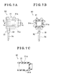
- Fig. 7A is a front view of an elastic member according to the embodiment of the present invention.
- Fig. 7B is a view viewed from arrow D of Fig. 7A.
- Fig. 7C is a cross-sectional view taken on line 7C-7C of Fig. 7A.
- Figs. 8A-8C are schematic views of assembling operation for the bumper antenna.
- Fig. 9 is a view viewed from arrow G of Fig. 8C.
- Fig. 10 is an enlarged view of a portion H shown in Fig. 9.
- a bumper antenna, or a trunk antenna (i.e., serving as an antenna device) 10 is one of parts which construct a smart entry system.
- the bumper antenna 10 locks and unlocks an opening and closing body such as a backdoor, trunk lid, or the like, which covers luggage space without operating switches of a remote controller and without operating a mechanical key.
- the bumper antenna 10 is provided in the vicinity of the luggage space for a vehicle.
- the bumper antenna 10 includes a bar antenna 11 and a case 20.
- the bar antenna 11 establishes communication between the vehicle and the electronic key which the user of the vehicle carries.
- the case 20 holds the bar antenna 11 through an elastic member 30 and is fixed to a body panel 9 (body of the vehicle) in a bumper cover of the vehicle.
- the detailed construction of the bar antenna 11, the case 20, and the elastic member 30 will be explained as follows referring to Figs. 4-7.
- the bar antenna 11 includes an antenna core 12 and a wire 13.
- the antenna core 12 (i.e., serving as a core portion) is, for example, made of ferrite which is one of magnetic materials, and is formed in a bar shape.
- the wire 13 (i.e., insulated wire) includes a wire core which is formed by twisting copper wires and covering material made of insulator for covering the wire core.
- the wire 13 is coiled around the antenna core 12. With the foregoing construction, a predetermined length of leading end portion 14 is provided at ends of the wire 13.
- the core portion may be made of soft magnetic materials such as cobalt amorphous, ferrous amorphous, amorphous alloy, nanocrystal magnetic alloy other than ferrite. Further, the core portion may be made from layers of magnetic ribbons which are made of materials mentioned above.
- the case 20 includes a body 21 and a cover 22.
- the body 21 made of resin is shaped into approximately long shape.
- the body 21 includes a housing portion 21a and a fixing portion 21b.
- the housing portion 21a is shaped to have a recess in a thickness direction of the body 21 (i.e., direction T of Fig. 5A).
- the fixing portion 21b is provided at each side of the body 21 in a longitudinal direction of the body 21 (i.e., direction L of Fig. 5A).
- the body 21 is fixed on a body panel 9 (shown in Fig. 3) using a tightening member such as a bolt.
- the cover 22 made of resin likewise the body 21 is formed in approximately long and thin plate shape.
- the cover 22 is configured to be fitted into the body 21.
- the cover 22 and the body 21 are fitted each other so that a thickness direction of the body 21 is arranged corresponding to a thickness direction of the cover 22 (i.e., direction T of Fig. 6A), and a longitudinal direction of the body 21 is arranged corresponding to a longitudinal direction of the cover 22 (i.e., direction L of fig. 6A).
- the cover 22 is formed with opposing wall portions 22a, 22b, a holding portion 22c, and an attaching hole 22d.
- the opposing wall portions 22a, 22b are provided at each side in a width direction (i.e., direction W of Fig. 6B) of the cover 22, and are arranged opposing each other.
- the opposing wall portions 22a, 22b are extended in a thickness direction of the cover 22.
- the bar antenna 11 is held between the opposing wall portions 22a, 22b.
- the holding portion 22c is provided facing the opposing wall portion 22a.
- the holding portion 22c includes a groove formed in a thickness direction of the cover 22.
- the leading end portion 14 of the wire 13 of the bar antenna 11 is housed in the groove of the holding portion 22c.
- the leading end portion 14 of the wire 13 is held relative to the cover 44.
- the attaching hole 22d is provided at each end of the cover 22 in a longitudinal direction of the cover 22.
- the attaching hole 22d is penetrated through the cover 22 in the thickness direction.
- the elastic member 30 is fitted into the attaching hole 22d. The construction of the elastic member 30 will be explained referring to Fig. 7.
- the elastic member 30 is made from an elastic body made of such as rubber and elastomer.
- the elastic member 30 is formed approximately in box shape (i.e., a case having a bottom).
- the elastic member 30 includes a fitting portion 31 and an attaching portion 32.
- the fitting portion 31 includes a recess portion formed in right and left direction (i.e., right, left direction of Fig. 7A) of the elastic member 30.
- the antenna core 12 of the bar antenna 11 is fitted into the fitting portion 31 to be assembled.
- a projection 31a is formed on an internal surface of the fitting portion 31.
- the attaching portion 32 is unitarily formed on the fitting portion 31, and extends in upward and downward direction (i.e., upward and downward direction of Fig. 7A) of the elastic member 30.
- the elastic member 30 is fitted to the attaching hole 22d of the cover 22 at the attaching portion 32.
- the attaching portion 32 is provided with a wedge portion 33 and a handle portion 34 in order nearside of fitting portion 31.
- the wedge portion 33 is tapered in a downward direction (i.e., downward direction of Fig. 7A) of the elastic member 30, and is shaped approximately in wedge shape.
- the elastic member 30 is fitted to the attaching hole 22d of the cover 22, the wedge portion 33 is fitted to the attaching hole 22d of the cover 22.
- the handle portion 34 is formed at an end of the wedge portion 33, and is formed in a pin shape. When the elastic member 30 is fitted to the attaching hole 22d of the cover 22, the handle portion 34 is inserted into the attaching hole 22d of the cover 22 before the wedge portion 33.
- the elastic member 30 is fitted at each end of the antenna core 12 of the bar antenna 11.
- the handle portion 34 of the elastic member 30 is inserted into the attaching hole 22d formed on the cover 22.
- the handle portion 34 inserted into the attaching hole 22d of the cover 22 is pulled towards arrow F of Fig. 8B, the wedge portion 33 of the elastic member 30 is elastically deformed and inserted into the attaching hole 22d, and eventually, the wedge portion 33 of the elastic member 30 is fitted to the attaching hole 22d.
- the leading end portion 14 of the wire 13 of the bar antenna 11 is housed in the holding portion 22c (shown in Fig. 6) shaped in a groove formed on the cover 22.
- the elastic member 30 is fixed on the cover 22, and the leading end portion 14 of the wire 13 is held relative to the cover 22.
- the bar antenna 11 After assembling an adhesive tape, a protective tube, and a connector at a remaining portion of the leading end portion 14 of the wire 13, by fitting the cover 22 to the body 21, the bar antenna 11 is housed in the housing portion 21a of the body 21.
- the bar antenna 11 is held at the case 20 through the elastic member 30, and the assembling operation of the bumper antenna 10 is completed.
- the elastic member 30 fitted to the antenna core 12 of the bar antenna 11 contact an internal surface of the housing portion 21a with pressure. Accordingly, the elastic member 30 is press-fitted into the housing portion 21a of the body 21.
- the holding portion 22c formed on the cover 22 includes the groove.
- the construction of the holding portion 22c of the present invention is not limited to the groove configuration, and for example, may include a craw shape which can hold the leading end portion 14 of the wire 13 relative to the cover 22.
- the case 20 holds the bar antenna 11 through the elastic member 30.
- the elastic member 30 is made from an elastic body made of rubber or elastomer, or the like. That is, because the elastic member 30 is solid when assembling to the antenna core 12, cure time (i.e., waiting time) of resin which is necessarily generated when holding the bar antenna 11 using potting material (i.e., resin) is not necessary. Accordingly, the time required to hold the bar antenna 11 at the case 20 is reduced, and the man-hour for assembling the bumper antenna 10 can be reduced.
- the leading end portion 14 of the wire 13 coiled around the antenna core 12 of the bar antenna 11 is held by the holding portion 22c including the groove formed, in advance, on the cover 20. Accordingly, the wire 13 coiled around the antenna core 12 is unlikely unwound, and the bumper antenna 10 can be assembled efficiently, and the ease of assembly of the bumper antenna 10 is increased.
- the wedge portion 33 and the handle portion 34 are provided in advance on the elastic member 30, and the attaching hole 22d fitted to the wedge portion 33 is provided on the case 20.
- the wedge portion 33 is fitted to the attaching hole 22d, and thus the elastic member 30 is fixed to the case 20.
- the case holds the bar made of ferrite by means of the elastic member.
- the elastic member is solid when being assembled, the cure time (i.e., waiting time) for resin which is generated with the known construction in which potting material (i.e., resin) is used and accounts for a part of man-hour for assembling operation of an antenna is not necessary. Accordingly, the bar made of ferrite can be held at the case with shorter time, and thus man-hour required for assembling the antenna can be reduced.
- the leading end portion of the wire coiled around the bar made of ferrite is held by the holding portion which is provided on the case in advance.
- the fitting portion and the handle portion are formed on the elastic member in advance, and the attaching hole configured to be fitted to the fitting portion is provided at the case.
- the elastic member is fixed to the case. Because the elastic member and the case are connected by means of a snap-fit structure, it is not necessary to provide separate parts for fixing the elastic member to the case. Accordingly, the number of parts for the antenna is reduced.
- An antenna device includes a core portion (21) made of magnetic material, a wire (13) coiled around the core portion leaving a leading end portion by a predetermined length, a case (20) holding the core portion on which the wire is coiled and fixed on a body of a vehicle, and an elastic member (30) provided between the core portion and the case for holding the core portion relative to the case.
Landscapes
- Engineering & Computer Science (AREA)
- Computer Security & Cryptography (AREA)
- Radar, Positioning & Navigation (AREA)
- Remote Sensing (AREA)
- Support Of Aerials (AREA)
- Details Of Aerials (AREA)
Abstract
Description
- The present invention relates to an antenna device.
- An antenna which establishes communication between an electronic key which an owner of a vehicle carries and a vehicle is provided on a smart entry system. A known antenna is described in JP2001-345615A.
- The known antenna includes a ferrite member and an electric conductive wire. The antenna is made by coiling an electric conductive wire around a ferrite member, and is housed in a case which is made of resin. Potting material (i.e., resin) is injected into the case in order to hold the antenna and to waterproof the antenna.
- Generally, ferrite includes low mechanical intensity and is likely to break. Accordingly, the antenna made of ferrite is required to be provided with resistance to vibration and resistance to impact by another means. Further, with an antenna including a core portion made of magnetic material other than ferrite, it is also favorable that the antenna is provided with resistance to vibration and resistance to impact considering that the antenna is mounted on a vehicle. With the known antenna described in JP2001-345615A, the ferrite member is protected from oscillation and impact by means of potting material injected into the case.
- Notwithstanding, potting material requires cure time. In other words, a waiting time during which operation is not conducted is generated until the potting material is cured in a series of assembling operation from inserting the antenna in the case to holding the antenna in the case. Thus, in terms of a view for productivity (i.e., ease of assembly), there is room for improvement.
- A need thus exists for an antenna device which can reduce man-hour for assembling an antenna.
- In light of the foregoing, the present invention provides an antenna device, which includes a core portion made of magnetic material, a wire coiled around the core portion leaving a leading end portion by a predetermined length, a case holding the core portion on which the wire is coiled and fixed on a body of a vehicle, and an elastic member provided between the core portion and the case for holding the core portion relative to the case.
- According to present invention, the case holds the core portion by means of the elastic member. With this construction, oscillation and impact transmitted from the body of the vehicle to the core portion is mitigated. Further, because the elastic member is solid when being assembled, the cure time (i.e., waiting time) for resin which is generated with the known construction in which potting material (i.e., resin) is used and accounts for a part of man-hour for assembling operation of an antenna is not necessary. Accordingly, the core portion can be held at the case with shorter time, and thus man-hour required for assembling the antenna can be reduced.
- The foregoing and additional features and characteristics of the present invention will become more apparent from the following detailed description considered with reference to the accompanying drawings, wherein:
- Fig. 1 is a front view showing an overview of a bumper antenna according to an embodiment of the present invention.
- Fig. 2 is a top view showing an overview of the bumper antenna according to the embodiment of the present invention.
- Fig. 3 is a cross-sectional view taken on line III-III of Fig. 2.
- Fig. 4 is a view showing a structure of a bar antenna.
- Fig. 5A is a front view of a body of a case according to the embodiment of the present invention.
- Fig. 5B is a cross-sectional view taken on
line 5B-5B of Fig. 5A. - Fig. 6A is a front view of a cover showing structure of the cover of the case according to the embodiment of the present invention.
- Fig. 6B is a top view of the cover according to the embodiment of the present invention.
- Fig. 6C is a cross-sectional view taken on
line 6C-6C of Fig. 6B. - Fig. 7A is a front view of an elastic member according to the embodiment of the present invention.
- Fig. 7B is a view viewed from arrow D of Fig. 7A.
- Fig. 7C is a cross-sectional view taken on
line 7C-7C of Fig. 7A. - Figs. 8A-8C are schematic views of assembling operation for the bumper antenna.
- Fig. 9 is a view viewed from arrow G of Fig. 8C.
- Fig. 10 is an enlarged view of a portion H shown in Fig. 9.
- One embodiment of the present invention will be explained with reference to illustrations of drawing figures as follows.
- As shown in Fig.1, a bumper antenna, or a trunk antenna (i.e., serving as an antenna device) 10 is one of parts which construct a smart entry system. The
bumper antenna 10 locks and unlocks an opening and closing body such as a backdoor, trunk lid, or the like, which covers luggage space without operating switches of a remote controller and without operating a mechanical key. Thebumper antenna 10 is provided in the vicinity of the luggage space for a vehicle. - When a user who has an electronic key pushes a switch which is provided in the vicinity of the opening and closing body when the opening and closing body is locked, electric wave is transmitted from the vehicle to the electronic key via the
bumper antenna 10. Receiving the electric wave at the electronic key, an ID code is identified between the electronic key and the vehicle, and when the ID code is matched, the opening and closing body is unlocked. - The
bumper antenna 10 includes abar antenna 11 and acase 20. - The
bar antenna 11 establishes communication between the vehicle and the electronic key which the user of the vehicle carries. Thecase 20 holds thebar antenna 11 through anelastic member 30 and is fixed to a body panel 9 (body of the vehicle) in a bumper cover of the vehicle. The detailed construction of thebar antenna 11, thecase 20, and theelastic member 30 will be explained as follows referring to Figs. 4-7. - The
bar antenna 11 includes anantenna core 12 and awire 13. - The antenna core 12 (i.e., serving as a core portion) is, for example, made of ferrite which is one of magnetic materials, and is formed in a bar shape. The wire 13 (i.e., insulated wire) includes a wire core which is formed by twisting copper wires and covering material made of insulator for covering the wire core. The
wire 13 is coiled around theantenna core 12. With the foregoing construction, a predetermined length of leadingend portion 14 is provided at ends of thewire 13. The core portion may be made of soft magnetic materials such as cobalt amorphous, ferrous amorphous, amorphous alloy, nanocrystal magnetic alloy other than ferrite. Further, the core portion may be made from layers of magnetic ribbons which are made of materials mentioned above. - The
case 20 includes abody 21 and acover 22. - The
body 21 made of resin is shaped into approximately long shape. Thebody 21 includes ahousing portion 21a and a fixingportion 21b. Thehousing portion 21a is shaped to have a recess in a thickness direction of the body 21 (i.e., direction T of Fig. 5A). The fixingportion 21b is provided at each side of thebody 21 in a longitudinal direction of the body 21 (i.e., direction L of Fig. 5A). Thebody 21 is fixed on a body panel 9 (shown in Fig. 3) using a tightening member such as a bolt. - The
cover 22 made of resin likewise thebody 21 is formed in approximately long and thin plate shape. Thecover 22 is configured to be fitted into thebody 21. Thecover 22 and thebody 21 are fitted each other so that a thickness direction of thebody 21 is arranged corresponding to a thickness direction of the cover 22 (i.e., direction T of Fig. 6A), and a longitudinal direction of thebody 21 is arranged corresponding to a longitudinal direction of the cover 22 (i.e., direction L of fig. 6A). - The
cover 22 is formed with opposingwall portions portion 22c, and an attachinghole 22d. - The opposing
wall portions cover 22, and are arranged opposing each other. The opposingwall portions cover 22. Thebar antenna 11 is held between the opposingwall portions - The holding
portion 22c is provided facing the opposingwall portion 22a. The holdingportion 22c includes a groove formed in a thickness direction of thecover 22. Theleading end portion 14 of thewire 13 of thebar antenna 11 is housed in the groove of the holdingportion 22c. Thus, theleading end portion 14 of thewire 13 is held relative to the cover 44. - The attaching
hole 22d is provided at each end of thecover 22 in a longitudinal direction of thecover 22. The attachinghole 22d is penetrated through thecover 22 in the thickness direction. Theelastic member 30 is fitted into the attachinghole 22d. The construction of theelastic member 30 will be explained referring to Fig. 7. - The
elastic member 30 is made from an elastic body made of such as rubber and elastomer. Theelastic member 30 is formed approximately in box shape (i.e., a case having a bottom). Theelastic member 30 includes afitting portion 31 and an attachingportion 32. - The
fitting portion 31 includes a recess portion formed in right and left direction (i.e., right, left direction of Fig. 7A) of theelastic member 30. Theantenna core 12 of thebar antenna 11 is fitted into thefitting portion 31 to be assembled. Aprojection 31a is formed on an internal surface of thefitting portion 31. When theantenna core 12 of thebar antenna 11 is fitted into thefitting portion 31, theprojection 31a presses the outer surface of theantenna core 12. In other words, theantenna core 12 is press-fitted into thefitting portion 31. - The attaching
portion 32 is unitarily formed on thefitting portion 31, and extends in upward and downward direction (i.e., upward and downward direction of Fig. 7A) of theelastic member 30. Theelastic member 30 is fitted to the attachinghole 22d of thecover 22 at the attachingportion 32. - The attaching
portion 32 is provided with awedge portion 33 and ahandle portion 34 in order nearside offitting portion 31. - The
wedge portion 33 is tapered in a downward direction (i.e., downward direction of Fig. 7A) of theelastic member 30, and is shaped approximately in wedge shape. When theelastic member 30 is fitted to the attachinghole 22d of thecover 22, thewedge portion 33 is fitted to the attachinghole 22d of thecover 22. - The
handle portion 34 is formed at an end of thewedge portion 33, and is formed in a pin shape. When theelastic member 30 is fitted to the attachinghole 22d of thecover 22, thehandle portion 34 is inserted into the attachinghole 22d of thecover 22 before thewedge portion 33. - The assembling operation of the
bumper antenna 10 will be explained with reference to Figs. 8-10. - As shown in Fig. 8A, first, the
elastic member 30 is fitted at each end of theantenna core 12 of thebar antenna 11. - As shown in Fig. 8B, second, the
handle portion 34 of theelastic member 30 is inserted into the attachinghole 22d formed on thecover 22. When thehandle portion 34 inserted into the attachinghole 22d of thecover 22 is pulled towards arrow F of Fig. 8B, thewedge portion 33 of theelastic member 30 is elastically deformed and inserted into the attachinghole 22d, and eventually, thewedge portion 33 of theelastic member 30 is fitted to the attachinghole 22d. Thereafter, theleading end portion 14 of thewire 13 of thebar antenna 11 is housed in the holdingportion 22c (shown in Fig. 6) shaped in a groove formed on thecover 22. At this point, as shown in Figs. 8C, 9, 10, theelastic member 30 is fixed on thecover 22, and theleading end portion 14 of thewire 13 is held relative to thecover 22. - After assembling an adhesive tape, a protective tube, and a connector at a remaining portion of the
leading end portion 14 of thewire 13, by fitting thecover 22 to thebody 21, thebar antenna 11 is housed in thehousing portion 21a of thebody 21. Thus, thebar antenna 11 is held at thecase 20 through theelastic member 30, and the assembling operation of thebumper antenna 10 is completed. Under a state where thebar antenna 11 is housed in thehousing portion 21a of thebody 21, theelastic member 30 fitted to theantenna core 12 of thebar antenna 11 contact an internal surface of thehousing portion 21a with pressure. Accordingly, theelastic member 30 is press-fitted into thehousing portion 21a of thebody 21. - With the foregoing explanations of the embodiment of the present invention, the holding
portion 22c formed on thecover 22 includes the groove. However, the construction of the holdingportion 22c of the present invention is not limited to the groove configuration, and for example, may include a craw shape which can hold theleading end portion 14 of thewire 13 relative to thecover 22. - As explained above, according to the
bumper antenna 10 of the present invention, thecase 20 holds thebar antenna 11 through theelastic member 30. With this construction, impact and oscillation transmitted from thebody panel 9 of the vehicle to thebar antenna 11 and theantenna core 12 is mitigated. Theelastic member 30 is made from an elastic body made of rubber or elastomer, or the like. That is, because theelastic member 30 is solid when assembling to theantenna core 12, cure time (i.e., waiting time) of resin which is necessarily generated when holding thebar antenna 11 using potting material (i.e., resin) is not necessary. Accordingly, the time required to hold thebar antenna 11 at thecase 20 is reduced, and the man-hour for assembling thebumper antenna 10 can be reduced. - Further, according to the embodiment of the present invention, the
leading end portion 14 of thewire 13 coiled around theantenna core 12 of thebar antenna 11 is held by the holdingportion 22c including the groove formed, in advance, on thecover 20. Accordingly, thewire 13 coiled around theantenna core 12 is unlikely unwound, and thebumper antenna 10 can be assembled efficiently, and the ease of assembly of thebumper antenna 10 is increased. - Further, according to the embodiment of the present invention, the
wedge portion 33 and thehandle portion 34 are provided in advance on theelastic member 30, and the attachinghole 22d fitted to thewedge portion 33 is provided on thecase 20. By pulling thehandle portion 34 after inserting thehandle portion 34 to the attachinghole 22d, thewedge portion 33 is fitted to the attachinghole 22d, and thus theelastic member 30 is fixed to thecase 20. With the foregoing construction, because theelastic member 30 and thecase 20 are fixed to each other by means of snap-fit structure, it is not necessary to provide additional parts when fixing theelastic member 30 to thecase 20. Accordingly, the number of parts of thebumper antenna 10 is reduced. - According to the embodiment of the present invention, the case holds the bar made of ferrite by means of the elastic member. With this construction, oscillation and impact transmitted from the body of the vehicle to the bar made of ferrite is mitigated. Further, because the elastic member is solid when being assembled, the cure time (i.e., waiting time) for resin which is generated with the known construction in which potting material (i.e., resin) is used and accounts for a part of man-hour for assembling operation of an antenna is not necessary. Accordingly, the bar made of ferrite can be held at the case with shorter time, and thus man-hour required for assembling the antenna can be reduced.
- According to the embodiment of the present invention, the leading end portion of the wire coiled around the bar made of ferrite is held by the holding portion which is provided on the case in advance. With this construction, because the wire coiled around the bar made of ferrite is unlikely unwound, the antenna can be assembled efficiently, and ease of assembly of the antenna is increased.
- According to the embodiment of the present invention, the fitting portion and the handle portion are formed on the elastic member in advance, and the attaching hole configured to be fitted to the fitting portion is provided at the case. By fitting the fitting portion to the attaching hole by pulling the handle portion after inserting the handle portion into the attaching hole, the elastic member is fixed to the case. Because the elastic member and the case are connected by means of a snap-fit structure, it is not necessary to provide separate parts for fixing the elastic member to the case. Accordingly, the number of parts for the antenna is reduced.
- The principles, preferred embodiment and mode of operation of the present invention have been described in the foregoing specification. However, the invention which is intended to be protected is not to be construed as limited to the particular embodiment disclosed. Further, the embodiments described herein are to be regarded as illustrative rather than restrictive. Variations and changes may be made by others, and equivalents employed, without departing from the spirit of the present invention. Accordingly, it is expressly intended that all such variations, changes and equivalents which fall within the spirit and scope of the present invention as defined in the claims, be embraced thereby.
An antenna device includes a core portion (21) made of magnetic material, a wire (13) coiled around the core portion leaving a leading end portion by a predetermined length, a case (20) holding the core portion on which the wire is coiled and fixed on a body of a vehicle, and an elastic member (30) provided between the core portion and the case for holding the core portion relative to the case.
Claims (9)
- An antenna device comprising:a core portion (12) made of magnetic material;a wire (13) coiled around the core portion leaving a leading end portion by a predetermined length;a case (20) holding the core portion on which the wire is coiled and fixed on a body of a vehicle; andan elastic member (30) provided between the core portion and the case for holding the core portion relative to the case.
- The antenna device according to Claim 1, wherein the core portion is made of ferrite.
- The antenna device according to either one of Claims 1-2, wherein the elastic member is made from an elastic body made of rubber or elastomer.
- The antenna device according to Claim 3, wherein the core portion is shaped in a bar; and
the elastic member includes a fitting portion (31) to which at least a part of the core portion is inserted to hold the core portion and an attaching portion (32) for fixing the fitting portion to the case. - The antenna device according to Claim 4, wherein the fitting portion is provided at ends of the core portion in a longitudinal direction thereof, and the ends of the core portion is fitted into the fitting portion.
- The antenna device according to Claim 4, further comprising:a projection (31a) formed on an internal surface of the fitting portion to which the core portion is fitted; and whereinthe projection presses the outer surface of the core portion.
- The antenna device according to Claim 4, wherein the attaching portion is formed on the fitting portion and extends in a direction which is perpendicular to a longitudinal direction of the core portion at a state where the core portion is fitted into the fitting portion.
- The antenna device according to Claim 4, wherein the attaching portion of the elastic member includes a wedge portion (33) having a wedge shape and a handle portion (34) formed continuously from the wedge portion;
the case is formed with an attaching hole (22d) fitted to the wedge portion; and
the elastic member is fixed to the case by fitting the fitting portion to the attaching hole by pulling the handle portion after inserting the handle portion through the attaching hole. - The antenna device according to Claim 1, further comprising:a holding portion provided in the case in advance and holds a leading end portion of the wire.
Applications Claiming Priority (1)
| Application Number | Priority Date | Filing Date | Title |
|---|---|---|---|
| JP2005018437A JP4337742B2 (en) | 2005-01-26 | 2005-01-26 | Antenna device |
Publications (2)
| Publication Number | Publication Date |
|---|---|
| EP1686652A1 true EP1686652A1 (en) | 2006-08-02 |
| EP1686652B1 EP1686652B1 (en) | 2009-07-29 |
Family
ID=36225987
Family Applications (1)
| Application Number | Title | Priority Date | Filing Date |
|---|---|---|---|
| EP06100530A Ceased EP1686652B1 (en) | 2005-01-26 | 2006-01-18 | Antenna device |
Country Status (5)
| Country | Link |
|---|---|
| US (1) | US7307593B2 (en) |
| EP (1) | EP1686652B1 (en) |
| JP (1) | JP4337742B2 (en) |
| CN (1) | CN2867627Y (en) |
| DE (1) | DE602006008050D1 (en) |
Families Citing this family (5)
| Publication number | Priority date | Publication date | Assignee | Title |
|---|---|---|---|---|
| JP4428388B2 (en) * | 2004-09-28 | 2010-03-10 | アイシン精機株式会社 | Antenna device and door handle device |
| JP4655230B2 (en) * | 2006-09-20 | 2011-03-23 | アイシン精機株式会社 | Bobbin for bar antenna, bar antenna and vehicle door handle |
| RU2458436C2 (en) * | 2010-11-08 | 2012-08-10 | Федеральное государственное унитарное предприятие "Омский научно-исследовательский институт приборостроения" (ФГУП "ОНИИП") | Shock absorber for mobile antenna |
| JP6280898B2 (en) * | 2015-08-26 | 2018-02-14 | 株式会社東海理化電機製作所 | Antenna device |
| CN105945237B (en) * | 2016-06-29 | 2018-11-27 | 江苏中伟业通讯设备有限公司 | The casting method of multi-functional installation part |
Citations (5)
| Publication number | Priority date | Publication date | Assignee | Title |
|---|---|---|---|---|
| US3154281A (en) * | 1962-02-20 | 1964-10-27 | Frank Charles | Holder for electronic components |
| US3294347A (en) | 1965-05-27 | 1966-12-27 | Gen Electric | Antenna support structure |
| US4275400A (en) * | 1977-08-08 | 1981-06-23 | Masashi Miyakoshi | Antenna coil and its support structure mounting |
| US20020033777A1 (en) * | 2000-06-13 | 2002-03-21 | Kota Maruyama | Bar antenna and method of manufacturing the same |
| US20050006909A1 (en) * | 2003-04-22 | 2005-01-13 | Aisin Seiki Kabushiki Kaisha | Vehicle door handle device |
Family Cites Families (16)
| Publication number | Priority date | Publication date | Assignee | Title |
|---|---|---|---|---|
| JPS54170754U (en) * | 1978-05-23 | 1979-12-03 | ||
| JPS54154245A (en) * | 1978-05-26 | 1979-12-05 | Matsushita Electric Ind Co Ltd | Ferrite antenna |
| JPS5611506U (en) * | 1979-07-04 | 1981-01-31 | ||
| JPS60203002A (en) * | 1984-03-28 | 1985-10-14 | Matsushita Electric Ind Co Ltd | Ferrite antenna assembly method |
| JPS6239903A (en) * | 1985-08-15 | 1987-02-20 | Nissan Motor Co Ltd | On-vehicle antenna system |
| JPH0751824Y2 (en) * | 1990-06-08 | 1995-11-22 | 名取 賢吉 | PCB mounting fixture |
| JP3826370B2 (en) * | 1997-01-09 | 2006-09-27 | 株式会社エフ・イー・シー | Antenna element for portable communication terminal |
| JP2000214275A (en) * | 1999-01-20 | 2000-08-04 | Rhythm Watch Co Ltd | Antenna device for radio wave correcting watch |
| DE10107319A1 (en) * | 2000-02-18 | 2002-01-31 | Aisin Seiki | Loop antenna device |
| JP2001345615A (en) * | 2000-05-31 | 2001-12-14 | Aisin Seiki Co Ltd | Door handle built-in antenna |
| JP4660887B2 (en) * | 2000-06-13 | 2011-03-30 | アイシン精機株式会社 | Door handle with bar antenna |
| JP3509790B2 (en) * | 2000-08-09 | 2004-03-22 | アイシン精機株式会社 | Vehicle door lock device |
| DE10044936A1 (en) | 2000-09-12 | 2002-04-04 | Bosch Gmbh Robert | Bumper antenna assembly |
| JP2003283231A (en) * | 2002-03-26 | 2003-10-03 | Aisin Seiki Co Ltd | Antenna and manufacturing method thereof |
| JP3826897B2 (en) * | 2003-04-22 | 2006-09-27 | アイシン精機株式会社 | Antenna device with sensor, door handle device |
| US7167140B2 (en) * | 2003-07-02 | 2007-01-23 | Nec Tokin Corporation | Coil antenna |
-
2005
- 2005-01-26 JP JP2005018437A patent/JP4337742B2/en not_active Expired - Fee Related
-
2006
- 2006-01-13 US US11/331,009 patent/US7307593B2/en not_active Expired - Fee Related
- 2006-01-18 CN CNU2006200024399U patent/CN2867627Y/en not_active Expired - Lifetime
- 2006-01-18 EP EP06100530A patent/EP1686652B1/en not_active Ceased
- 2006-01-18 DE DE602006008050T patent/DE602006008050D1/en not_active Expired - Lifetime
Patent Citations (5)
| Publication number | Priority date | Publication date | Assignee | Title |
|---|---|---|---|---|
| US3154281A (en) * | 1962-02-20 | 1964-10-27 | Frank Charles | Holder for electronic components |
| US3294347A (en) | 1965-05-27 | 1966-12-27 | Gen Electric | Antenna support structure |
| US4275400A (en) * | 1977-08-08 | 1981-06-23 | Masashi Miyakoshi | Antenna coil and its support structure mounting |
| US20020033777A1 (en) * | 2000-06-13 | 2002-03-21 | Kota Maruyama | Bar antenna and method of manufacturing the same |
| US20050006909A1 (en) * | 2003-04-22 | 2005-01-13 | Aisin Seiki Kabushiki Kaisha | Vehicle door handle device |
Also Published As
| Publication number | Publication date |
|---|---|
| CN2867627Y (en) | 2007-02-07 |
| EP1686652B1 (en) | 2009-07-29 |
| DE602006008050D1 (en) | 2009-09-10 |
| JP2006211121A (en) | 2006-08-10 |
| JP4337742B2 (en) | 2009-09-30 |
| US20060164311A1 (en) | 2006-07-27 |
| US7307593B2 (en) | 2007-12-11 |
Similar Documents
| Publication | Publication Date | Title |
|---|---|---|
| US7598915B2 (en) | Bobbin for bar antenna, antenna and door handle for a vehicle | |
| US7210715B2 (en) | Door handle device | |
| EP1862620B1 (en) | Door handle apparatus for a vehicle | |
| US7095381B2 (en) | Antenna coil | |
| EP2003621B1 (en) | Door handle for vehicle and smart entry system for vehicle using the same | |
| CN101118983B (en) | Antenna device | |
| US20120133563A1 (en) | Antenna unit and door handle device including the same | |
| US20050006909A1 (en) | Vehicle door handle device | |
| JP3696866B2 (en) | Door opener | |
| KR101939077B1 (en) | Door handle and antenna unit | |
| CN104640744B (en) | Vehicle door lock control system | |
| EP3012391A1 (en) | Vehicle door handle | |
| EP1686652B1 (en) | Antenna device | |
| JP2007009414A (en) | Anti-theft system for vehicle | |
| JP4595547B2 (en) | Vehicle door handle device | |
| JP6555579B2 (en) | ANTENNA DEVICE, VEHICLE EQUIPPED WITH THE SAME, AND BOBBIN MANUFACTURING METHOD | |
| JP3639292B1 (en) | Door opener | |
| JP2017123523A (en) | Antenna device and vehicle having the same | |
| JP6395263B2 (en) | ANTENNA DEVICE AND VEHICLE HAVING THE SAME | |
| JP2017017652A (en) | Antenna device and vehicle having the same | |
| JP4244707B2 (en) | Door handle device | |
| JP4321099B2 (en) | Door handle grip | |
| CN110364816A (en) | Antenna coil and antenna device | |
| JP4617851B2 (en) | Antenna device | |
| KR20130003684U (en) | Antenna of IP box for vehicle |
Legal Events
| Date | Code | Title | Description |
|---|---|---|---|
| PUAI | Public reference made under article 153(3) epc to a published international application that has entered the european phase |
Free format text: ORIGINAL CODE: 0009012 |
|
| AK | Designated contracting states |
Kind code of ref document: A1 Designated state(s): AT BE BG CH CY CZ DE DK EE ES FI FR GB GR HU IE IS IT LI LT LU LV MC NL PL PT RO SE SI SK TR |
|
| AX | Request for extension of the european patent |
Extension state: AL BA HR MK YU |
|
| 17P | Request for examination filed |
Effective date: 20070201 |
|
| AKX | Designation fees paid |
Designated state(s): DE FR |
|
| 17Q | First examination report despatched |
Effective date: 20080117 |
|
| GRAP | Despatch of communication of intention to grant a patent |
Free format text: ORIGINAL CODE: EPIDOSNIGR1 |
|
| GRAS | Grant fee paid |
Free format text: ORIGINAL CODE: EPIDOSNIGR3 |
|
| GRAA | (expected) grant |
Free format text: ORIGINAL CODE: 0009210 |
|
| AK | Designated contracting states |
Kind code of ref document: B1 Designated state(s): DE FR |
|
| REF | Corresponds to: |
Ref document number: 602006008050 Country of ref document: DE Date of ref document: 20090910 Kind code of ref document: P |
|
| PLBE | No opposition filed within time limit |
Free format text: ORIGINAL CODE: 0009261 |
|
| STAA | Information on the status of an ep patent application or granted ep patent |
Free format text: STATUS: NO OPPOSITION FILED WITHIN TIME LIMIT |
|
| 26N | No opposition filed |
Effective date: 20100503 |
|
| REG | Reference to a national code |
Ref country code: FR Ref legal event code: PLFP Year of fee payment: 11 |
|
| REG | Reference to a national code |
Ref country code: FR Ref legal event code: PLFP Year of fee payment: 12 |
|
| REG | Reference to a national code |
Ref country code: FR Ref legal event code: PLFP Year of fee payment: 13 |
|
| PGFP | Annual fee paid to national office [announced via postgrant information from national office to epo] |
Ref country code: FR Payment date: 20221208 Year of fee payment: 18 |
|
| PGFP | Annual fee paid to national office [announced via postgrant information from national office to epo] |
Ref country code: DE Payment date: 20221130 Year of fee payment: 18 |
|
| REG | Reference to a national code |
Ref country code: DE Ref legal event code: R119 Ref document number: 602006008050 Country of ref document: DE |
|
| PG25 | Lapsed in a contracting state [announced via postgrant information from national office to epo] |
Ref country code: DE Free format text: LAPSE BECAUSE OF NON-PAYMENT OF DUE FEES Effective date: 20240801 |
|
| PG25 | Lapsed in a contracting state [announced via postgrant information from national office to epo] |
Ref country code: FR Free format text: LAPSE BECAUSE OF NON-PAYMENT OF DUE FEES Effective date: 20240131 |
|
| PG25 | Lapsed in a contracting state [announced via postgrant information from national office to epo] |
Ref country code: FR Free format text: LAPSE BECAUSE OF NON-PAYMENT OF DUE FEES Effective date: 20240131 Ref country code: DE Free format text: LAPSE BECAUSE OF NON-PAYMENT OF DUE FEES Effective date: 20240801 |