EP1686355A1 - Method and system for monitoring the flow of multiphase mixtures - Google Patents
Method and system for monitoring the flow of multiphase mixtures Download PDFInfo
- Publication number
- EP1686355A1 EP1686355A1 EP05405710A EP05405710A EP1686355A1 EP 1686355 A1 EP1686355 A1 EP 1686355A1 EP 05405710 A EP05405710 A EP 05405710A EP 05405710 A EP05405710 A EP 05405710A EP 1686355 A1 EP1686355 A1 EP 1686355A1
- Authority
- EP
- European Patent Office
- Prior art keywords
- gas
- flow rate
- volume flow
- liquid
- phase
- Prior art date
- Legal status (The legal status is an assumption and is not a legal conclusion. Google has not performed a legal analysis and makes no representation as to the accuracy of the status listed.)
- Ceased
Links
- 239000000203 mixture Substances 0.000 title claims abstract description 57
- 238000000034 method Methods 0.000 title claims abstract description 26
- 238000012544 monitoring process Methods 0.000 title description 4
- 239000007788 liquid Substances 0.000 claims abstract description 57
- 239000012071 phase Substances 0.000 claims abstract description 37
- 239000007791 liquid phase Substances 0.000 claims abstract description 30
- 230000002596 correlated effect Effects 0.000 claims abstract description 24
- 238000005259 measurement Methods 0.000 claims abstract description 8
- 230000003247 decreasing effect Effects 0.000 claims abstract description 7
- 230000007423 decrease Effects 0.000 claims description 5
- 238000004519 manufacturing process Methods 0.000 claims description 5
- 238000000926 separation method Methods 0.000 claims description 2
- 239000007789 gas Substances 0.000 description 70
- 238000007796 conventional method Methods 0.000 description 5
- XLYOFNOQVPJJNP-UHFFFAOYSA-N water Substances O XLYOFNOQVPJJNP-UHFFFAOYSA-N 0.000 description 4
- 238000012423 maintenance Methods 0.000 description 3
- 230000008901 benefit Effects 0.000 description 2
- 238000009833 condensation Methods 0.000 description 2
- 230000005494 condensation Effects 0.000 description 2
- 230000001276 controlling effect Effects 0.000 description 2
- 230000000875 corresponding effect Effects 0.000 description 2
- 239000010779 crude oil Substances 0.000 description 2
- 230000001419 dependent effect Effects 0.000 description 2
- 238000001704 evaporation Methods 0.000 description 2
- 230000008020 evaporation Effects 0.000 description 2
- 239000012530 fluid Substances 0.000 description 2
- VNWKTOKETHGBQD-UHFFFAOYSA-N methane Chemical compound C VNWKTOKETHGBQD-UHFFFAOYSA-N 0.000 description 2
- 238000002156 mixing Methods 0.000 description 2
- 238000012360 testing method Methods 0.000 description 2
- 238000010276 construction Methods 0.000 description 1
- 238000012937 correction Methods 0.000 description 1
- 238000013461 design Methods 0.000 description 1
- 238000001514 detection method Methods 0.000 description 1
- 230000000694 effects Effects 0.000 description 1
- 238000000265 homogenisation Methods 0.000 description 1
- 239000000463 material Substances 0.000 description 1
- 239000003345 natural gas Substances 0.000 description 1
- 239000003921 oil Substances 0.000 description 1
- 239000003208 petroleum Substances 0.000 description 1
- 238000004886 process control Methods 0.000 description 1
- 238000003908 quality control method Methods 0.000 description 1
- 239000000523 sample Substances 0.000 description 1
- 229920006395 saturated elastomer Polymers 0.000 description 1
Images
Classifications
-
- G—PHYSICS
- G01—MEASURING; TESTING
- G01F—MEASURING VOLUME, VOLUME FLOW, MASS FLOW OR LIQUID LEVEL; METERING BY VOLUME
- G01F1/00—Measuring the volume flow or mass flow of fluid or fluent solid material wherein the fluid passes through a meter in a continuous flow
- G01F1/74—Devices for measuring flow of a fluid or flow of a fluent solid material in suspension in another fluid
-
- G—PHYSICS
- G01—MEASURING; TESTING
- G01F—MEASURING VOLUME, VOLUME FLOW, MASS FLOW OR LIQUID LEVEL; METERING BY VOLUME
- G01F1/00—Measuring the volume flow or mass flow of fluid or fluent solid material wherein the fluid passes through a meter in a continuous flow
- G01F1/05—Measuring the volume flow or mass flow of fluid or fluent solid material wherein the fluid passes through a meter in a continuous flow by using mechanical effects
- G01F1/34—Measuring the volume flow or mass flow of fluid or fluent solid material wherein the fluid passes through a meter in a continuous flow by using mechanical effects by measuring pressure or differential pressure
- G01F1/36—Measuring the volume flow or mass flow of fluid or fluent solid material wherein the fluid passes through a meter in a continuous flow by using mechanical effects by measuring pressure or differential pressure the pressure or differential pressure being created by the use of flow constriction
-
- G—PHYSICS
- G01—MEASURING; TESTING
- G01F—MEASURING VOLUME, VOLUME FLOW, MASS FLOW OR LIQUID LEVEL; METERING BY VOLUME
- G01F1/00—Measuring the volume flow or mass flow of fluid or fluent solid material wherein the fluid passes through a meter in a continuous flow
- G01F1/76—Devices for measuring mass flow of a fluid or a fluent solid material
- G01F1/86—Indirect mass flowmeters, e.g. measuring volume flow and density, temperature or pressure
- G01F1/88—Indirect mass flowmeters, e.g. measuring volume flow and density, temperature or pressure with differential-pressure measurement to determine the volume flow
Definitions
- the invention relates to a method and an arrangement for determining the mass flow rate and the gas / liquid ratio in a multiphase mixture during production, as well as a conveyor system for multiphase mixtures for carrying out such a method or comprising such an arrangement.
- a device for mixing and measuring a multiphase fluid which comprises a container to which the gaseous and liquid components are supplied and a perforated collecting pipe to discharge and mix the gaseous and liquid components from the container. Following the manifold, a venturi is provided to determine the mass flow, and a Densiometer to measure the density of the multiphase fluid.
- the known from WO 90/13859 device has the disadvantage that a densiometer is used, for example, works with gamma rays and high costs and a corresponding maintenance required.
- the object of the invention is to provide a method and an arrangement for determining the mass flow rate and the gas / liquid ratio in a multiphase mixture during production, as well as a conveyor system for multiphase mixtures for carrying out such a method and / or comprising such an arrangement which avoid the disadvantages of the prior art.
- the inventive method for determining the mass flow and the gas / liquid ratio in a multiphase mixture during the promotion of the pressure of the multiphase mixture is between increases or decreases two measuring points and detects at the two measuring points in each case one with the volume flow, in particular with the total volume flow, or with the flow rate, in particular with the flow rate of the multiphase mixture, correlated measured variable.
- the gas / liquid ratio and / or the volume flow rate of the liquid phase and the gas phase and / or the mass flow rate of the liquid phase and the gas phase are then determined on the basis of the measured quantities recorded.
- a pump in particular a pump for multi-phase mixtures, or a turbine, in particular an expansion turbine can be used.
- a Venturi nozzle and / or an orifice plate and / or a volumetric flow meter are used in each case to detect the measured variables correlated with the volumetric flow.
- the term "orifice plate” is understood below to mean any type of device with calibrated pressure loss, such as nozzles, orifices or probes.
- a pressure difference in a Venturi nozzle and / or a pressure drop across a metering orifice and / or a flow rate and / or the volume flow itself are detected as measured variables correlated with the volume flow rate.
- the gas / liquid ratio is determined without the use of a separator or separation vessel.
- the acquisition of the measured values can take place, for example, in pipelines.
- the passage cross section in the region of the measuring points is not varied more than 50%, in particular not more than 20% or 10%.
- the volume flow values of the liquid phase and the gas phase determined according to the invention or the specific mass flow values of the liquid phase and the gas phase are used for controlling and / or monitoring the pump or turbine.
- the invention comprises an arrangement for determining the mass flow rate and the gas / liquid ratio in a multiphase mixture during the conveying, in which in the conveying direction successively a measuring device for detecting one with the volume flow, in particular with the entire volume flow, or with the flow rate, in particular are provided with the flow rate of the multiphase mixture, correlated measured variable, a device for increasing or decreasing the pressure and a further measuring device for detecting a correlated with the volume flow, in particular with the total volume flow, or with the flow rate, in particular with the flow rate of the multiphase mixture, measured quantity ,
- the device for increasing or decreasing the pressure can be embodied, for example, as a pump, in particular as a pump for multiphase mixtures, or as a turbine, in particular as an expansion turbine.
- the arrangement additionally comprises an arithmetic unit which is connected to the measuring devices for determining, preferably automatically determining, the gas / liquid ratio and / or the volume flow of the liquid phase and the gas phase and / or the mass flow of the liquid phase and the gas phase.
- the arithmetic unit 4 is connected to the control of the pump or turbine or integrated into the control thereof.
- the volume flow values or mass flow values of the liquid phase and the gas phase thus determined are used for controlling and / or monitoring the pump or turbine.
- the measuring devices for detecting the measured variables correlated with the volume flow are each designed as Venturi nozzle and / or as a measuring diaphragm and / or as a volumetric flow meter.
- the measuring devices are preferably arranged in pipelines for detecting the measured variables correlated with the volume flow or the measuring devices are designed such that the passage cross section in the region of the measuring devices does not vary more than 50%, in particular not more than 20% or 10%.
- the invention further comprises a conveyor system for multiphase mixtures for carrying out one or more of the above-mentioned methods and / or comprising one or more of the above-mentioned arrangements.
- the inventive method for determining the mass flow and the gas / liquid ratio in a multiphase mixture during the promotion has the advantage that it is simple and inexpensive executable compared to conventional methods. From the gas / liquid ratio and the measured quantities can be determined in a simple manner, the volume and mass flow of the liquid and gaseous portions of the multiphase mixture.
- the inventive arrangement can be advantageously assembled from standard components that require little additional maintenance in operation. The arrangement is also cost-effective because a Separator employer for separating the liquid and gas phase and / or a cost and maintenance-intensive Densiometer deleted and the measuring devices can be installed, for example, in pipelines.
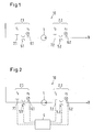
- Figure 1 shows a schematic representation of an embodiment of an arrangement 10 according to the present invention.
- a measuring device 5.1 for detecting a measured variable correlated with the volume flow in the conveying direction 9, a measuring device 5.1 for detecting a measured variable correlated with the volume flow, a device 1 for increasing or decreasing the pressure, and at a second measuring point 2.2 another measuring device 5.2 for detecting one with the volumetric flow are successively measured at a first measuring point 2.1 correlated measured variable provided.
- the device 1 is designed to increase or decrease the pressure as a pump, for example as a pump for multi-phase mixtures, or as a turbine, for example as an expansion turbine.
- a pipe line and in particular a riser for pressure reduction, other parts of a conveyor system are suitable, such as a pipe line and in particular a riser, as long as the ratio of existing at the two measuring points 2.1 and 2.2 pressure values sufficiently different from the value 1, for example, greater than 1.4 or less than 0.7 and advantageously larger than 2 or less than 0.5.
- the measuring devices (5.1, 5.2) for detecting the measured variables correlated with the volume flow are designed as Venturi nozzles in the exemplary embodiment.
- the pressure difference also called "effective pressure" between the inlet pressure and the pressure in the narrowest cross section is detected in a known manner.
- the pressure difference is dependent on the flow rate and thus on the volume flow of the multiphase mixture.
- other measuring devices can be used or other measured variables correlated with the volume flow rate can be detected. For example, by means of one or more orifices pressure drops and / or by means of one or more sensors, the flow rates or volume flow rates can be detected.
- the measuring points 2.1, 2.2 are additionally equipped with a respective pressure sensor 6.1, 6.2 and a temperature sensor 7.1, 7.2.
- the first venturi nozzle is arranged immediately in front of the intake manifold of the multiphase pump, for example within a distance L, where L / D ⁇ 3, so that the behavior of the pump can benefit from the homogenization of the flow caused by the venturi nozzle.
- the mass flow rate at the two measuring points is the same.
- the pressure at the measuring points is different.
- the volume flow of the gas phase at the two measuring points is different. From measurements of the volume flow and / or a measured variable correlated therewith at the two measuring points, a determination equation for the gas / liquid ratio can be determined, from which the gas / liquid ratio can be determined. With the aid of the gas / liquid ratio, the volume flow of the liquid phase and the gas phase and / or the mass flow of the liquid phase and the gas phase can then be determined.
- a determination equation for another transport variable for example for the volume flow of the liquid phase or the volume flow of the gas phase or the mass flow of the liquid phase or the mass flow of the gas phase can be determined the determination equation, the transport size in question can be determined. With the aid of the transport size determined in this way, the remaining transport quantities can then be calculated.
- the determination of the gas / liquid ratio depends in particular on which measured variables correlated with the volume flow rate are detected at the two measuring points 2.1, 2.2.
- the procedure at the Determination of the gas / liquid ratio will be explained below with reference to the embodiment.
- the pressure of the multiphase mixture between the two measuring points 2.1, 2.2 is increased by means of a multiphase pump and detected at both measuring points in each case the pressure difference ⁇ p 1 , ⁇ p 2 between the inlet pressure and the pressure in the narrowest cross section of a Venturi nozzle 5.1, 5.2.
- the pressure p 1 , p 2 and the temperature T 1 , T 2 of the multiphase mixture are detected at both measuring points.
- the procedure described is also suitable analogously for the determination of the gas / liquid ratio, if instead of the Venturi nozzles other measuring devices are used to detect the variables correlated with the volume flow.
- the equation (5) for GLR 1 can be solved, for example analytically by solving the corresponding quadratic equation for GLR 1 or iteratively, for example with one of the usual spreadsheet programs. From the gas / liquid ratio GLR 1 determined in this way, the other transport quantities, such as volume flow Q 1 'of the liquid phase, volume flow Q 1 "of the gas phase, mass flow rate ⁇ 1 ' of the liquid phase and mass flow rate m 1 " of the gas phase, can be calculated.
- the following calculation procedure is to be considered as an example only:
- ⁇ mix, 1 can be determined.
- the liquid density ⁇ 1 'must be known. If the multiphase mixture contains a variable proportion of water, which is frequently the case, for example, in the production of crude oil, according to a further embodiment variant, the water content W c in the liquid phase can be detected by means of a separate measuring sensor.
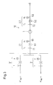
- the sensors of the Venturi nozzles 5.1, 5.2, as shown in FIG. 2 are connected to a computing unit 4 in order to evaluate the pressure differences of the Venturi nozzles detected at the two measuring points 2.1., 2.2.
- the determination of the gas / liquid ratio can be carried out in this case by means of the arithmetic unit 4.
- further transport quantities such as volume flow rate Q 1 'of the liquid phase, volume flow rate Q 1 "of the gas phase, mass flow rate m 1 ' of the liquid phase and mass flow rate m 1 " of the gas phase, can be calculated from the gas / liquid ratio. This results in the possibility of automatically and / or continuously monitoring the gas / liquid ratio and occasionally other transport sizes of a multiphase mixture.
- the measuring points 2.1, 2.2 are additionally equipped with a respective pressure sensor 6.1, 6.2 and a temperature sensor 7.1, 7.2, which are also connected to the arithmetic unit 4.
- This arrangement allows an automatic and / or continuous determination of the gas / liquid ratio and occasionally further derived therefrom transport sizes with an over conventional methods, such as that of WO 95/26494, improved accuracy.
- FIG. 3 shows a structure for calibrating an arrangement according to the present invention.
- a liquid mass flow m ' sep and a gaseous mass flow m " sep are fed into the arrangement 10 to be calibrated, which, for example, can be designed in accordance with the above-described embodiment
- the liquid and the gaseous mass flow are each provided via their own supply line and their own measuring point 3 ', 3 "supplied for detecting the volume and / or mass flow, so that the flow of the liquid and the gas phase can be detected separately.
- the separate volume and / or mass flow can be detected, for example, by means of a venturi nozzle or metering orifice.
- a pressure sensor and a temperature sensor are additionally provided at the measuring points 3 ', 3 "for separate detection of the flow of the liquid and the gas phase.
- the calibration of the arrangement 10 for determining the mass flow and the gas / liquid ratio is advantageously carried out on the test bench in the context of the acceptance test of the pump 1, wherein expediently the Venturi nozzles 5.1, 5.2 used later in operation are installed.
- the same line arrangement is used as in the later operation, since the line arrangement in operation is often not ideal and often required for venturi standard lengths for the straight-line supply and discharge can not be met. Such deviations from the ideal geometry are thus taken into account in the flow factors f FP1 , f FP2 of the venturi nozzles 5.1, 5.2 of the arrangement 10.
- the mass flow rate ⁇ ' sep , ⁇ " sep of the separately supplied liquid phase and gas phase is measured, and the resulting mass flow rate m 1 , ⁇ 2 in the venturi nozzles 5.1, 5.2 of the arrangement 10 to be calibrated.
- the ratio between the flow rate by means of the venturi nozzles 5.1, 5.2 specific mass flow m 1 , ⁇ 2 and the measurements of the separately supplied liquid phase and gas phase is taken into account in the flow factors f FP1 , f FP2 :
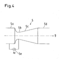
- the venturi nozzle 5 comprises in succession a straight inlet 5a of constant cross section, a narrowest point 5b of reduced cross section and a funnel-shaped expanding diffuser 5c which merges into a straight outlet 5d of constant cross section.
- a sensor 5e is provided to detect the pressure difference between the supply pressure in the supply line 5a and the pressure at the narrowest point 5b.
- the method according to the invention for determining the mass flow rate and the gas / liquid ratio in a multiphase mixture is characterized in that it can be carried out in a simpler and less expensive manner than conventional methods, such as, for example, WO 95/26494.
- the thus determined values of the gas / liquid ratio are more accurate than those with said values determined by conventional methods.
- the used parts of the inventive arrangement are robust and require, apart from the sensors of the measuring devices, no additional maintenance. If required, further flow values, in particular the flow of the liquid and the gas phase, can be calculated from the gas / liquid ratio determined in this way without additional measurement expenditure.
Landscapes
- Physics & Mathematics (AREA)
- Fluid Mechanics (AREA)
- General Physics & Mathematics (AREA)
- Measuring Volume Flow (AREA)
Abstract
Description
Die Erfindung betrifft ein Verfahren und eine Anordnung zur Bestimmung des Massendurchflusses und des Gas/Flüssigkeits-Verhältnisses in einem Mehrphasengemisch während der Förderung, sowie eine Förderanlage für Mehrphasengemische zur Ausführung eines derartigen Verfahrens oder umfassend eine derartige Anordnung.The invention relates to a method and an arrangement for determining the mass flow rate and the gas / liquid ratio in a multiphase mixture during production, as well as a conveyor system for multiphase mixtures for carrying out such a method or comprising such an arrangement.
Bei der Förderung von Mehrphasengemischen, wie beispielsweise Rohöl, das neben Erdöl auch Erdgas und häufig auch Wasser enthält, stellt sich das Problem, das nicht nur der gesamte Massendurchfluss zu bestimmen ist, sondern auch das Gas/Flüssigkeits-Verhältnis im geförderten Mehrphasengemisch. Die Kenntnis des Massendurchflusses und des Gas/Flüssigkeits-Verhältnisses sind von grosser praktischer Bedeutung, beispielsweise für die Rechnungsstellung, für die Steuerung der Mehrphasenpumpe und für die Prozessteuerung, insbesondere für die Einstellung der Förderrate und die Qualitätsüberwachung.In the production of multiphase mixtures, such as crude oil, which in addition to petroleum also contains natural gas and often water, there is the problem that is not only the total mass flow to determine, but also the gas / liquid ratio in the funded multiphase mixture. The knowledge of the mass flow and the gas / liquid ratio are of great practical importance, for example for billing, for the control of the multiphase pump and for the process control, in particular for the adjustment of the delivery rate and the quality control.
Aus WO 90/13859 ist eine Vorrichtung zum mischen und Messen eines mehrphasigen Fluids bekannt, das einen Behälter aufweist, dem die gasförmigen und flüssigen Anteile zugeführt werden und ein perforiertes Sammelrohr, um die gasförmigen und flüssigen Anteile aus dem Behälter abzuleiten und zu mischen. Im Anschluss an das Sammelrohr sind eine Venturidüse vorgesehen, um den Massendurchfluss zu bestimmen, und ein Densiometer, um die Dichte des mehrphasigen Fluids zu messen. Die aus WO 90/13859 bekannte Vorrichtung hat den Nachteil, dass ein Densiometer verwendet wird, das z.B. mit Gammastrahlen arbeitet und hohe Kosten sowie einen entsprechenden Wartungsaufwand erfordert.From WO 90/13859 a device for mixing and measuring a multiphase fluid is known which comprises a container to which the gaseous and liquid components are supplied and a perforated collecting pipe to discharge and mix the gaseous and liquid components from the container. Following the manifold, a venturi is provided to determine the mass flow, and a Densiometer to measure the density of the multiphase fluid. The known from WO 90/13859 device has the disadvantage that a densiometer is used, for example, works with gamma rays and high costs and a corresponding maintenance required.
In der Veröffentlichung WO 95/26494 ist eine Vorrichtung und ein Verfahren zum Mischen, Messen und Fördern eines Mehrphasengemisches offenbart, welche einen Buffertank zur Trennung der flüssigen und gasförmigen Anteile verwenden. Der Massendurchfluss des gasförmigen Anteils wird bei diesem Verfahren separat erfasst, bevor die flüssigen und gasförmigen Anteile in einem Sammelrohr wieder zusammengeführt und weiterbefördert werden. Weiter kann aus dem Druck des gasförmigen Anteils, dem Druck im Sammelrohr und der Höhe des Flüssigkeitsspiegels im Buffertank und einer Venturimessung der gesamte Massendurchfluss berechnet werden.In the publication WO 95/26494 an apparatus and a method for mixing, measuring and conveying a multiphase mixture are disclosed which use a buffertank for separating the liquid and gaseous portions. The mass flow rate of the gaseous fraction is detected separately in this process, before the liquid and gaseous components are combined in a collecting tube and transported on. Furthermore, from the pressure of the gaseous fraction, the pressure in the manifold and the height of the liquid level in the buffertank and a venturi measurement, the total mass flow can be calculated.
Die aus dem Stand der Technik bekannten Verfahren und Vorrichtungen zur Bestimmung des Massendurchflusses und des Gas/Flüssigkeits-Verhältnisses in einem Mehrphasengemisch haben den Nachteil, dass sie aufwändig sind und je nach Ausführung einen relativ grossen Separatorbehälter und/oder ein kosten- und wartungsintensives Densiometer benötigen. Zudem ist die Genauigkeit der herkömmlichen Verfahren beschränkt.The methods and devices known from the prior art for determining the mass flow rate and the gas / liquid ratio in a multiphase mixture have the disadvantage that they are complex and, depending on the design, require a relatively large separator container and / or a costly and maintenance-intensive densiometer , In addition, the accuracy of the conventional methods is limited.
Aufgabe der Erfindung ist es, ein Verfahren und eine Anordnung zur Bestimmung des Massendurchflusses und des Gas/Flüssigkeits-Verhältnisses in einem Mehrphasengemisch während der Förderung, sowie eine Förderanlage für Mehrphasengemische zur Ausführung eines derartigen Verfahrens und/oder umfassend eine derartige Anordnung zur Verfügung zu stellen, welche die Nachteile aus dem Stand der Technik vermeiden.The object of the invention is to provide a method and an arrangement for determining the mass flow rate and the gas / liquid ratio in a multiphase mixture during production, as well as a conveyor system for multiphase mixtures for carrying out such a method and / or comprising such an arrangement which avoid the disadvantages of the prior art.
Diese Aufgabe wird erfindungsgemäss durch das in Anspruch 1 definierte Verfahren, und die in Anspruch 7 definierte Anordnung gelöst, sowie durch die in Anspruch 12 definierte Förderanlage.This object is achieved according to the invention by the method defined in
Im erfindungsgemässen Verfahren zur Bestimmung des Massendurchflusses und des Gas/Flüssigkeits-Verhältnisses in einem Mehrphasengemisch während der Förderung wird der Druck des Mehrphasengemisches zwischen zwei Messstellen erhöht oder vermindert und an den beiden Messstellen jeweils eine mit dem Volumendurchfluss, insbesondere mit dem gesamten Volumendurchfluss, oder mit der Durchflussgeschwindigkeit, insbesondere mit der Durchflussgeschwindigkeit des Mehrphasengemisches, korrelierte Messgrösse erfasst. Sodann wird auf Grund der erfassten Messgrössen das Gas/Flüssigkeits-Verhältnis und/oder der Volumendurchfluss der Flüssigphase und der Gasphase und/oder der Massendurchfluss der Flüssigphase und der Gasphase bestimmt. Zur Erhöhung oder Verminderung des Druckes kann beispielsweise eine Pumpe, insbesondere eine Pumpe für Mehrphasengemische, oder eine Turbine, insbesondere eine Entspannungsturbine, verwendet werden.In the inventive method for determining the mass flow and the gas / liquid ratio in a multiphase mixture during the promotion of the pressure of the multiphase mixture is between increases or decreases two measuring points and detects at the two measuring points in each case one with the volume flow, in particular with the total volume flow, or with the flow rate, in particular with the flow rate of the multiphase mixture, correlated measured variable. The gas / liquid ratio and / or the volume flow rate of the liquid phase and the gas phase and / or the mass flow rate of the liquid phase and the gas phase are then determined on the basis of the measured quantities recorded. To increase or decrease the pressure, for example, a pump, in particular a pump for multi-phase mixtures, or a turbine, in particular an expansion turbine can be used.
In einer bevorzugten Ausführungsform wird zur Erfassung der mit dem Volumendurchfluss korrelierten Messgrössen jeweils eine Venturidüse und/oder eine Messblende und/oder ein Volumendurchflussmesser verwendet. Unter der Bezeichnung "Messblende" wird im folgenden jegliche Art von Vorrichtung mit geeichtem Druckverlust verstanden, wie beispielsweise Düsen, Blenden oder Sonden. Vorzugsweise wird als mit dem Volumendurchfluss korrelierte Messgrössen jeweils ein Druckunterschied in einer Venturidüse und/oder ein Druckabfall über eine Messblende und/oder eine Durchflussgeschwindigkeit und/oder der Volumendurchfluss selbst erfasst.In a preferred embodiment, a Venturi nozzle and / or an orifice plate and / or a volumetric flow meter are used in each case to detect the measured variables correlated with the volumetric flow. The term "orifice plate" is understood below to mean any type of device with calibrated pressure loss, such as nozzles, orifices or probes. Preferably, a pressure difference in a Venturi nozzle and / or a pressure drop across a metering orifice and / or a flow rate and / or the volume flow itself are detected as measured variables correlated with the volume flow rate.
Vorzugsweise wird das Gas/Flüssigkeits-Verhältnis ohne Benützung eines Separators oder Trennbehälters bestimmt. Die Erfassung der Messwerte kann beispielsweise in Rohrleitungen erfolgen. Vorzugsweise wird der Durchlassquerschnitt im Bereich der Messstellen nicht mehr als 50 %, insbesondere nicht mehr als 20 % oder 10% variiert.Preferably, the gas / liquid ratio is determined without the use of a separator or separation vessel. The acquisition of the measured values can take place, for example, in pipelines. Preferably, the passage cross section in the region of the measuring points is not varied more than 50%, in particular not more than 20% or 10%.
In einer bevorzugten Ausführungsvariante werden die erfindungsgemäss bestimmten Volumendurchflusswerte der Flüssigphase und der Gasphase beziehungsweise die bestimmten Massendurchflusswerte der Flüssigphase und der Gasphase zur Regelung und/oder Überwachung der Pumpe oder Turbine verwendet werden.In a preferred embodiment variant, the volume flow values of the liquid phase and the gas phase determined according to the invention or the specific mass flow values of the liquid phase and the gas phase are used for controlling and / or monitoring the pump or turbine.
Weiter umfasst die Erfindung eine Anordnung zur Bestimmung des Massendurchflusses und des Gas/Flüssigkeits-Verhältnisses in einem Mehrphasengemisch während der Förderung, in welcher in Förderrichtung nacheinander eine Messvorrichtung zur Erfassung einer mit dem Volumendurchfluss, insbesondere mit dem gesamten Volumendurchfluss, oder mit der Durchflussgeschwindigkeit, insbesondere mit der Durchflussgeschwindigkeit des Mehrphasengemisches, korrelierten Messgrösse, eine Vorrichtung zur Erhöhung oder Verminderung des Druckes und eine weitere Messvorrichtung zur Erfassung einer mit dem Volumendurchfluss, insbesondere mit dem gesamten Volumendurchfluss, oder mit der Durchflussgeschwindigkeit, insbesondere mit der Durchflussgeschwindigkeit des Mehrphasengemisches, korrelierten Messgrösse vorgesehen sind. Die Vorrichtung zur Erhöhung oder Verminderung des Druckes kann beispielsweise als Pumpe, insbesondere als Pumpe für Mehrphasengemische, oder als Turbine, insbesondere als Entspannungsturbine, ausgeführt sein.Furthermore, the invention comprises an arrangement for determining the mass flow rate and the gas / liquid ratio in a multiphase mixture during the conveying, in which in the conveying direction successively a measuring device for detecting one with the volume flow, in particular with the entire volume flow, or with the flow rate, in particular are provided with the flow rate of the multiphase mixture, correlated measured variable, a device for increasing or decreasing the pressure and a further measuring device for detecting a correlated with the volume flow, in particular with the total volume flow, or with the flow rate, in particular with the flow rate of the multiphase mixture, measured quantity , The device for increasing or decreasing the pressure can be embodied, for example, as a pump, in particular as a pump for multiphase mixtures, or as a turbine, in particular as an expansion turbine.
In einer bevorzugten Ausführungsform umfasst die Anordnung zusätzlich eine Recheneinheit, die mit den Messvorrichtungen verbunden ist, zur Bestimmung, vorzugsweise automatischen Bestimmung, des Gas/Flüssigkeits-Verhältnisses und/oder des Volumendurchflusses der Flüssigphase und der Gasphase und/oder des Massendurchflusses der Flüssigphase und der Gasphase. Vorzugsweise ist die Recheneinheit 4 mit der Steuerung der Pumpe oder Turbine verbunden oder in die Steuerung derselben integriert. Zweckmässigerweise werden die derart bestimmten Volumendurchflusswerte beziehungsweise Massendurchflusswerte der Flüssigphase und der Gasphase zur Regelung und/oder Überwachung der Pumpe oder Turbine verwendet.In a preferred embodiment, the arrangement additionally comprises an arithmetic unit which is connected to the measuring devices for determining, preferably automatically determining, the gas / liquid ratio and / or the volume flow of the liquid phase and the gas phase and / or the mass flow of the liquid phase and the gas phase. Preferably, the
In einer weiteren bevorzugten Ausführungsform sind die Messvorrichtungen zur Erfassung der mit dem Volumendurchfluss korrelierten Messgrössen jeweils als Venturidüse und/oder als Messblende und/oder als Volumendurchflussmesser ausgeführt.In a further preferred embodiment, the measuring devices for detecting the measured variables correlated with the volume flow are each designed as Venturi nozzle and / or as a measuring diaphragm and / or as a volumetric flow meter.
Vorzugsweise sind die Messvorrichtungen zur Erfassung der mit dem Volumendurchfluss korrelierten Messgrössen in Rohrleitungen angeordnet oder die Messvorrichtungen derart ausgebildet sind, dass der Durchlassquerschnitt im Bereich der Messvorrichtungen nicht mehr als 50 %, insbesondere nicht mehr als 20 % oder 10 % variiert.The measuring devices are preferably arranged in pipelines for detecting the measured variables correlated with the volume flow or the measuring devices are designed such that the passage cross section in the region of the measuring devices does not vary more than 50%, in particular not more than 20% or 10%.
Weiter umfasst die Erfindung eine Förderanlage für Mehrphasengemische zur Ausführung eines oder mehrerer der oben genannten Verfahren und/oder enthaltend eine oder mehrere der oben genannten Anordnungen.The invention further comprises a conveyor system for multiphase mixtures for carrying out one or more of the above-mentioned methods and / or comprising one or more of the above-mentioned arrangements.
Das erfindungsgemässe Verfahren zur Bestimmung des Massendurchflusses und des Gas/Flüssigkeits-Verhältnisses in einem Mehrphasengemisch während der Förderung hat den Vorteil, dass dasselbe verglichen mit herkömmlichen Verfahren einfach und kostengünstig ausführbar ist. Aus dem Gas/Flüssigkeits-Verhältnis und den erfassten Messgrössen kann in einfacher Weise der Volumen- und Massendurchfluss der flüssigen und der gasförmigen Anteile des Mehrphasengemisches bestimmt werden. Die erfindungsgemässe Anordnung kann in vorteilhafter Weise aus Standardbauteilen zusammengestellt werden, die im Betrieb wenig zusätzlichen Wartungsaufwand erfordern. Die Anordnung ist auch deshalb kostengünstig, weil ein Separatorbehälter zur Trennung der Flüssig- und Gasphase und/oder ein kosten- und wartungsintensives Densiometer entfällt und die Messvorrichtungen beispielsweise in Rohrleitungen eingebaut werden können.The inventive method for determining the mass flow and the gas / liquid ratio in a multiphase mixture during the promotion has the advantage that it is simple and inexpensive executable compared to conventional methods. From the gas / liquid ratio and the measured quantities can be determined in a simple manner, the volume and mass flow of the liquid and gaseous portions of the multiphase mixture. The inventive arrangement can be advantageously assembled from standard components that require little additional maintenance in operation. The arrangement is also cost-effective because a Separatorbehälter for separating the liquid and gas phase and / or a cost and maintenance-intensive Densiometer deleted and the measuring devices can be installed, for example, in pipelines.
Weitere vorteilhafte Ausführungsformen gehen aus den abhängigen Ansprüchen und der Zeichnung hervor.Further advantageous embodiments will become apparent from the dependent claims and the drawings.
Im Folgenden wird die Erfindung an Hand des Ausführungsbeispiels und an Hand der Zeichnung näher erläutert. Es zeigen:
- Fig. 1
- eine schematische Darstellung eines Ausführungsbeispiels einer Anordnung gemäss vorliegender Erfindung,
- Fig. 2
- eine Ausführungsvariante mit Recheneinheit zu dem in Fig. 1 gezeigten Ausführungsbeispiel,
- Fig. 3
- einen Aufbau zum Eichen einer Anordnung gemäss vorliegender Erfindung, und
- Fig. 4
- Beispiel einer Messvorrichtung in Form einer Venturidüse aus dem in Fig. 1 gezeigten Ausführungsbeispiel.
- Fig. 1
- a schematic representation of an embodiment of an arrangement according to the present invention,
- Fig. 2
- an embodiment variant with arithmetic unit to the embodiment shown in Figure 1,
- Fig. 3
- a structure for calibrating an arrangement according to the present invention, and
- Fig. 4
- Example of a measuring device in the form of a Venturi nozzle from the embodiment shown in Fig. 1.
Figur 1 zeigt eine schematische Darstellung eines Ausführungsbeispiels einer Anordnung 10 gemäss vorliegender Erfindung. In dieser Anordnung sind in Förderrichtung 9 nacheinander an einer ersten Messstelle 2.1 eine Messvorrichtung 5.1 zur Erfassung einer mit dem Volumendurchfluss korrelierten Messgrösse, eine Vorrichtung 1 zur Erhöhung oder Verminderung des Druckes und an einer zweiten Messstelle 2.2 eine weitere Messvorrichtung 5.2 zur Erfassung einer mit dem Volumendurchfluss korrelierten Messgrösse vorgesehen. Im Ausführungsbeispiel ist die Vorrichtung 1 zur Erhöhung oder Verminderung des Druckes als Pumpe, beispielsweise als Pumpe für Mehrphasengemische, oder als Turbine, beispielsweise als Entspannungsturbine, ausgeführt. Zur Druckverminderung sind auch andere Teile einer Förderanlage geeignet, beispielsweise eine Rohrleitungsstrecke und insbesondere eine Steigleitung, solange sich das Verhältnis der an den beiden Messstellen 2.1 und 2.2 vorhandenen Druckwerte genügend vom Wert 1 unterscheidet, beispielsweise grösser als 1.4 oder kleiner als 0.7 und mit Vorteil grösser als 2 oder kleiner als 0.5 ist.Figure 1 shows a schematic representation of an embodiment of an
Die Messvorrichtungen (5.1, 5.2) zur Erfassung der mit dem Volumendurchfluss korrelierten Messgrössen sind im Ausführungsbeispiel als Venturidüsen ausgeführt. In den Venturidüsen wird in bekannter Weise der Druckunterschied (auch "Wirkdruck" genannt) zwischen dem Zulaufdruck und dem Druck im engsten Querschnitt erfasst. Der Druckunterschied ist abhängig von der Durchflussgeschwindigkeit und damit vom Volumendurchfluss des Mehrphasengemisches. Selbstverständlich können auch andere Messvorrichtungen verwendet werden beziehungsweise andere mit dem Volumendurchfluss korrelierte Messgrössen erfasst werden. Beispielsweise können mittels einer oder mehrerer Messblenden Druckabfälle und/oder mittels einem oder mehreren Aufnehmern die Durchflussgeschwindigkeiten oder Volumendurchflussraten erfasst werden.The measuring devices (5.1, 5.2) for detecting the measured variables correlated with the volume flow are designed as Venturi nozzles in the exemplary embodiment. In the Venturi nozzles, the pressure difference (also called "effective pressure") between the inlet pressure and the pressure in the narrowest cross section is detected in a known manner. The pressure difference is dependent on the flow rate and thus on the volume flow of the multiphase mixture. Of course, other measuring devices can be used or other measured variables correlated with the volume flow rate can be detected. For example, by means of one or more orifices pressure drops and / or by means of one or more sensors, the flow rates or volume flow rates can be detected.
In einer bevorzugten Ausführungsvariante sind die Messstellen 2.1, 2.2 zusätzlich mit je einem Druckaufnehmer 6.1, 6.2 und einem Temperaturaufnehmer 7.1, 7.2 ausgestattet. In einer weiteren bevorzugten Ausführungsvariante ist die erste Venturidüse unmittelbar vor dem Ansaugstutzen der Mehrphasenpumpe angeordnet, beispielsweise innerhalb eines Abstandes L, wobei L/D < 3, sodass das Verhalten der Pumpe von der durch die Venturidüse bewirkten Homogensierung des Flusses profitieren kann.In a preferred embodiment, the measuring points 2.1, 2.2 are additionally equipped with a respective pressure sensor 6.1, 6.2 and a temperature sensor 7.1, 7.2. In a further preferred embodiment variant, the first venturi nozzle is arranged immediately in front of the intake manifold of the multiphase pump, for example within a distance L, where L / D <3, so that the behavior of the pump can benefit from the homogenization of the flow caused by the venturi nozzle.
Zur Bestimmung des Gas/Flüssigkeits-Verhältnisses und des Massendurchflusses der Flüssigphase und der Gasphase wird davon ausgegangen, dass der Massendurchfluss an den beiden Messstellen gleich gross ist. In Folge der Druckerhöhung oder -Verminderung zwischen den Messstellen ist der Druck an den Messstellen jedoch unterschiedlich. Damit ist auch der Volumendurchfluss der Gasphase an den beiden Messstellen unterschiedlich. Aus Messungen des Volumendurchflusses und/oder einer damit korrelierten Messgrösse an den beiden Messstellen kann eine Bestimmungsgleichung für das Gas/Flüssigkeits-Verhältnis ermittelt werden, aus der sich das Gas/Flüssigkeits-Verhältnis bestimmen lässt. Mit Hilfe des Gas/Flüssigkeits-Verhältnisses kann anschliessend der Volumendurchfluss der Flüssigphase und der Gasphase und/oder der Massendurchfluss der Flüssigphase und der Gasphase bestimmt werden.To determine the gas / liquid ratio and the mass flow of the liquid phase and the gas phase, it is assumed that the mass flow rate at the two measuring points is the same. However, as a result of the pressure increase or decrease between the measuring points, the pressure at the measuring points is different. Thus, the volume flow of the gas phase at the two measuring points is different. From measurements of the volume flow and / or a measured variable correlated therewith at the two measuring points, a determination equation for the gas / liquid ratio can be determined, from which the gas / liquid ratio can be determined. With the aid of the gas / liquid ratio, the volume flow of the liquid phase and the gas phase and / or the mass flow of the liquid phase and the gas phase can then be determined.
In analoger Weise kann aus Messungen des Volumendurchflusses und/oder einer damit korrelierten Messgrösse an den beiden Messstellen eine Bestimmungsgleichung für eine andere Transportgrösse, beispielsweise für den Volumendurchfluss der Flüssigphase oder den Volumendurchfluss der Gasphase oder den Massendurchfluss der Flüssigphase oder den Massendurchfluss der Gasphase ermittelt und aus der Bestimmungsgleichung die betreffende Transportgrösse bestimmt werden. Mit Hilfe der derart bestimmten Transportgrösse können dann die übrigen Transportgrössen berechnet werden.In an analogous manner, from measurements of the volume flow rate and / or a measured quantity correlated therewith at the two measuring points, a determination equation for another transport variable, for example for the volume flow of the liquid phase or the volume flow of the gas phase or the mass flow of the liquid phase or the mass flow of the gas phase can be determined the determination equation, the transport size in question can be determined. With the aid of the transport size determined in this way, the remaining transport quantities can then be calculated.
Die Bestimmung des Gas/Flüssigkeits-Verhältnisses hängt insbesondere davon ab, welche mit dem Volumendurchfluss korrelierte Messgrössen an den beiden Messstellen 2.1, 2.2 erfasst werden. Das Vorgehen bei der Bestimmung des Gas/Flüssigkeits-Verhältnisses wird im Folgenden an Hand des Ausführungsbeispiels erläutert. Im Ausführungsbeispiel wird der Druck des Mehrphasengemisches zwischen den beiden Messstellen 2.1, 2.2 mittels einer Mehrphasenpumpe erhöht und an beiden Messstellen jeweils der Druckunterschied Δp1, Δp2 zwischen dem Zulaufdruck und dem Druck im engsten Querschnitt einer Venturidüse 5.1, 5.2 erfasst. Zusätzlich wird an beiden Messstellen jeweils der Druck p1, p2 und die Temperatur T1, T2 des Mehrphasengemisches erfasst. Die beschriebene Vorgehensweise eignet sich in analoger Weise auch für die Bestimmung des Gas/Flüssigkeits-Verhältnisses, wenn an Stelle der Venturidüsen andere Messvorrichtungen zur Erfassung der mit dem Volumendurchfluss korrelierten Messgrössen verwendet werden.The determination of the gas / liquid ratio depends in particular on which measured variables correlated with the volume flow rate are detected at the two measuring points 2.1, 2.2. The procedure at the Determination of the gas / liquid ratio will be explained below with reference to the embodiment. In the exemplary embodiment, the pressure of the multiphase mixture between the two measuring points 2.1, 2.2 is increased by means of a multiphase pump and detected at both measuring points in each case the pressure difference Δp 1 , Δp 2 between the inlet pressure and the pressure in the narrowest cross section of a Venturi nozzle 5.1, 5.2. In addition, the pressure p 1 , p 2 and the temperature T 1 , T 2 of the multiphase mixture are detected at both measuring points. The procedure described is also suitable analogously for the determination of the gas / liquid ratio, if instead of the Venturi nozzles other measuring devices are used to detect the variables correlated with the volume flow.
In dem in Fig. 1 gezeigten Ausführungsbeispiel ist der Massendurchfluss ṁ1, ṁ2 an beiden Messstellen 2.1, 2.2 gleich gross ist. D.h. 
Der Massendurchfluss einer Venturidüse ergibt sich z.B. aus folgender Formel: ![]()
![]()
Eingesetzt in Formel (1) erhält man damit: ![]()
mit
- A1, A2
- = Querschnitt der Venturidüse
- α1, α2
- = berechnete Durchflusszahl der Venturidüse
- ε1, ε2
- = Expansionskoeffizient der Venturidüse; kann gleich 1.0 gesetzt werden, insbesondere wenn der Durchflussfaktor, wie nachstehend beschrieben, durch Eichung bestimmt wird,
und - fFP1, fFP2
- = Durchflussfaktor der Venturidüse (Eichfunktion)
- ρmix,1, ρmix,2
- = Dichte des Mehrphasengemisches
- Δp1 , Δp2
- = gemessener Druckunterschied der Venturidüse
With
- A 1 , A 2
- = Cross-section of the Venturi nozzle
- α 1 , α 2
- = calculated flow rate of the Venturi nozzle
- ε 1 , ε 2
- = Coefficient of expansion of the Venturi nozzle; can be set equal to 1.0, in particular if the flow factor, as described below, is determined by calibration,
and - f FP1 , f FP2
- = Venturi nozzle flow factor (calibration function)
- ρ mix, 1 , ρ mix, 2
- = Density of the multiphase mixture
- Δp 1 , Δp 2
- = measured pressure difference of the Venturi nozzle
Die Dichte des Mehrphasengemisches beträgt: 
und 
mit
- ρ1', ρ2'
- = Flüssigdichte
- Q1', Q2'
- = Volumendurchfluss der Flüssigphase
- ρ1", ρ2"
- = Gasdichte
- Q1", Q2"
- = Volumendurchfluss der Gasphase
- GLR1 GLR2
- = Gas/Flüssigkeits-Verhältnis
and
With
- ρ 1 ', ρ 2 '
- = Liquid density
- Q 1 ', Q 2 '
- = Volume flow of the liquid phase
- ρ 1 ", ρ 2 "
- = Gas density
- Q 1 ", Q 2 "
- = Volume flow of the gas phase
- GLR 1 GLR 2
- = Gas / liquid ratio
Aus den Gleichungen (3), (4a) und (4b) erhält man folgende Gleichung für GLR1: 
Die Gasdichte ρ1" kann aus der Beziehung ρ1"= ![]()
- Z =
- realer Gasfaktor
- R1 =
- universelle Gaskonstante/M
und - M =
- Molekulargewicht.
- Z =
- real gas factor
- R 1 =
- universal gas constant / M
and - M =
- Molecular weight.
Die Flüssigdichte ρ1' = f(p1,T1) in Funktion des Druckes und der Temperatur ist aus Materialtabellen bekannt.The liquid density ρ1 '= f (p 1 , T 1 ) as a function of pressure and temperature is known from material tables.
Damit kann die Gleichung (5) für GLR1 gelöst werden, beispielsweise analytisch durch Lösung der entsprechenden quadratischen Gleichung für GLR1 oder iterativ, z.B. mit einem der üblichen Tabellenkalkulationsprogramme. Aus dem derart bestimmten Gas/Flüssigkeits-Verhältnis GLR1 können die übrigen Transportgrössen, wie Volumendurchfluss Q1' der Flüssigphase, Volumendurchfluss Q1" der Gasphase, Massendurchfluss ṁ1' der Flüssigphase und Massendurchfluss m1" der Gasphase, berechnet werden. Der folgende Berechnungsgang ist lediglich als Beispiel zu betrachten: Durch Einsetzen von GLR1 in Gleichung (4a) kann ρmix,1 bestimmt werden. Durch Einsetzen von ρmix,1 in Gleichung (2) erhält man den gesamten Massendurchfluss m1 und aus der Beziehung Q1 = 

Die Gleichungen (4a) bis (6) gelten nur für den Fall, dass die Verdampfung und Kondensation im Mehrphasengemisch und die Lösung von Gasen im Mehrphasengemisch vernachlässigbar sind. Falls die Effekte der Verdampfung/Kondensation oder der Lösung von Gasen im Mehrphasengemisch nicht vernachlässigbar sind, kann für die Bestimmung des Gas/Flüssigkeits-Verhältnisses in der selben Weise vorgegangen werden, wie im oben beschriebenen Ausführungsbeispiel, wobei der gasförmige Volumendurchfluss Q" nun aus einem nicht kondensierenden Gasanteil Qg und einem kondensierenden Gasanteil Qv besteht, der gesättigt ist, d.h. Q" = Qg + Qv.The equations (4a) to (6) apply only in the event that the evaporation and condensation in the multiphase mixture and the solution of gases in the multiphase mixture are negligible. If the effects of evaporation / condensation or the solution of gases in the multiphase mixture are not negligible, the determination of the gas / liquid ratio can be carried out in the same way as in the embodiment described above, wherein the gaseous volume flow Q "now from a non-condensed gas fraction Qg and a condensing gas content Q is v, which is saturated, that is, Q "= Q g + Q v.
Für die Bestimmung des Gas/Flüssigkeits-Verhältnisses gemäss dem oben beschriebenen Ausführungsbeispiel muss die Flüssigdichte ρ1' bekannt sein. Falls das Mehrphasengemisch einen variablen Wasseranteil (im Englischen als "water cut" bezeichnet) enthält, was beispielsweise bei der Förderung von Rohöl häufig der Fall ist, so kann gemäss einer weiteren Ausführungsvariante der Wasseranteil Wc in der Flüssigphase mittels eines separaten Messaufnehmers erfasst werden. Die Flüssigdichte ρ1' ergibt sich dann aus: 
In einer weiteren bevorzugten Ausführungsvariante sind die Messaufnehmer der Venturidüsen 5.1, 5.2, wie in Fig. 2 gezeigt, mit einer Recheneinheit 4 verbunden, um die an den beiden Messstellen 2.1., 2.2 erfassten Druckunterschiede der Venturidüsen auszuwerten. Die Bestimmung des Gas/Flüssigkeits-Verhältnisses kann in diesem Fall mittels der Recheneinheit 4 erfolgen. Aus dem Gas/Flüssigkeits-Verhältnis können, wie oben erwähnt, weitere Transportgrössen, wie Volumendurchfluss Q1' der Flüssigphase, Volumendurchfluss Q1" der Gasphase, Massendurchfluss m1' der Flüssigphase und Massendurchfluss m1" der Gasphase, berechnet werden. Damit ergibt sich die Möglichkeit, das Gas/Flüssigkeits-Verhältnis und fallweise weitere Transportgrössen eines Mehrphasengemisches automatisch und/oder kontinuierlich zu überwachen. Mit Vorteil sind die Messstellen 2.1, 2.2 zusätzlich mit je einem Druckaufnehmer 6.1, 6.2 und einem Temperaturaufnehmer 7.1, 7.2 ausgestattet, die ebenfalls mit der Recheneinheit 4 verbunden sind. Diese Anordnung gestattet eine automatische und/oder kontinuierliche Bestimmung des Gas/Flüssigkeits-Verhältnisses sowie fallweise weiterer daraus abgeleiteter Transportgrössen mit einer gegenüber herkömmlichen Verfahren, wie demjenigen aus WO 95/26494, verbesserten Genauigkeit.In a further preferred embodiment variant, the sensors of the Venturi nozzles 5.1, 5.2, as shown in FIG. 2, are connected to a
Da das oben beschriebene Verfahren zur Bestimmung des Massendurchflusses und des Gas/Flüssigkeits-Verhältnisses auch zur Rechnungsstellung eingesetzt werden kann, kommt der Eichung eine besondere Bedeutung zu. Fig. 3 zeigt einen Aufbau zum Eichen einer Anordnung gemäss vorliegender Erfindung. In diesem Aufbau werden gleichzeitig ein flüssiger Massenstrom m'sep und ein gasförmiger Massenstrom m"sep in die zu eichende Anordnung 10 eingespeist, die beispielsweise entsprechend dem oben beschriebenen Ausführungsbeispiel ausgeführt sein kann. Der flüssige und der gasförmige Massenstrom werden jeweils über eine eigene Zuleitung und eine eigene Messstelle 3', 3" zur Erfassung des Volumen- und/oder Massendurchflusses zugeführt, sodass der Durchfluss der Flüssig- und der Gasphase separat erfasst werden kann. Der separate Volumen- und/oder Massendurchfluss kann beispielsweise mittels einer Venturidüse oder Messblende erfasst werden. Vorzugsweise sind an den Messstellen-3', 3" zur separaten Erfassung des Durchflusses der Flüssig-und der Gasphase jeweils zusätzlich ein Druck- und ein Temperaturaufnehmer vorgesehen.Since the above-described method for determining the mass flow rate and the gas / liquid ratio can also be used for invoicing, the calibration is of particular importance. Fig. 3 shows a structure for calibrating an arrangement according to the present invention. In this construction will be at the same time a liquid mass flow m ' sep and a gaseous mass flow m " sep are fed into the
Die Eichung der Anordnung 10 zur Bestimmung des Massendurchflusses und des Gas/Flüssigkeits-Verhältnisses erfolgt mit Vorteil auf dem Prüfstand im Rahmen der Abnahmeprüfung der Pumpe 1, wobei zweckmässigerweise die später im Betrieb eingesetzten Venturidüsen 5.1, 5.2 eingebaut werden. Vorzugsweise wird auch dieselbe Leitungsanordnung verwendet wie im späteren Betrieb, da die Leitungsanordnung im Betrieb häufig nicht ideal ist und die für Venturidüsen verlangten Standardlängen für die gerade verlaufenden Zu- und Ableitung häufig nicht eingehalten werden können. Derartige Abweichungen von der idealen Geometrie werden somit in den Durchflussfaktoren fFP1, fFP2 der Venturidüsen 5.1, 5.2 der Anordnung 10 berücksichtigt.The calibration of the
Während der Eichung wird der Massendurchfluss ṁ'sep, ṁ"sep der separat zugeführten Flüssigphase und Gasphase gemessen sowie der resultierende Massendurchfluss m1, ṁ2 in den Venturidüsen 5.1, 5.2 der zu eichenden Anordnung 10. Das Verhältnis zwischen dem mittels der Venturidüsen 5.1, 5.2 bestimmten Massendurchfluss m1, ṁ2 und den Messungen der separat zugeführten Flüssigphase und Gasphase wird in den Durchflussfaktoren fFP1, fFP2 berücksichtigt: 
In Gleichung (5) wird nur das Verhältnis fFP1/fFP2 benötigt, womit die Korrektur und die damit verbundene Unsicherheit wesentlich reduziert werden. 
Die Faktoren fFP1, fFP2 und FFP werden für verschiedene Durchflusswerte und verschiedene Zusammensetzungen des Mehrphasengemisches bestimmt und als Funktion der Durchflusswerte und Zusammensetzung, beispielsweise als Funktion fFP oder FFP = f(G, GVF, ρ*), aufgezeichnet, um entsprechende Abhängigkeiten festzustellen. Dabei bedeutet: ![]()

und ρ* = p'/p" = Verhältnis von Flüssigdichte und GasdichteThe factors f FP1 , f FP2 and F FP are determined for various flow rates and different compositions of the multiphase mixture and recorded as a function of flow values and composition, for example as a function f FP or F FP = f (G, GVF, ρ *) determine appropriate dependencies. Where: ![]()
and ρ * = p '/ p "= ratio of liquid density and gas density
Fig. 4 zeigt ein Beispiel einer Messvorrichtung in Form einer Venturidüse aus dem oben beschriebenen Ausführungsbeispiel. Vorzugsweise wird zur Erfassung der mit dem Volumendurchfluss korrelierten Messgrösse eine Venturidüse nach ISO 5167 verwendet. In dem in Fig. 4 gezeigten Beispiel umfasst die Venturidüse 5 in Strömungsrichtung 9 nacheinander eine gerade Zuleitung 5a mit konstantem Querschnitt, eine engste Stelle 5b mit reduziertem Querschnitt und einen trichterförmig sich erweiternden Diffusor 5c, der in eine gerade Ableitung 5d mit konstantem Querschnitt übergeht. Zusätzlich ist ein Messaufnehmer 5e vorgesehen, um den Druckunterschied zwischen dem Zulaufdruck in der Zuleitung 5a und dem Druck an der engsten Stelle 5b zu erfassen.4 shows an example of a measuring device in the form of a venturi nozzle from the embodiment described above. Preferably, a venturi nozzle according to ISO 5167 is used to detect the measured variable correlated with the volume flow. In the example shown in FIG. 4, the
Das erfindungsgemässe Verfahren zur Bestimmung des Massendurchflusses und des Gas/Flüssigkeits-Verhältnisses in einem Mehrphasengemisch zeichnet sich dadurch aus, dass es verglichen mit herkömmlichen Verfahren, wie beispielsweise demjenigen aus WO 95/26494, einfacher und kostengünstiger ausführbar ist. Zudem sind die derart bestimmten Werte des Gas/Flüssigkeits-Verhältnisses genauer als die mit dem genannten herkömmlichen Verfahren bestimmten Werte. Die verwendeten Teile der erfindungsgemässen Anordnung sind robust und bedürfen, abgesehen von den Messaufnehmern der Messvorrichtungen, keiner zusätzlichen Wartung. Bei Bedarf können aus dem derart bestimmten Gas/Flüssigkeits-Verhältnis ohne zusätzlichen Messaufwand weitere Durchflusswerte, insbesondere der Durchfluss der Flüssig- und der Gasphase, berechnet werden.The method according to the invention for determining the mass flow rate and the gas / liquid ratio in a multiphase mixture is characterized in that it can be carried out in a simpler and less expensive manner than conventional methods, such as, for example, WO 95/26494. In addition, the thus determined values of the gas / liquid ratio are more accurate than those with said values determined by conventional methods. The used parts of the inventive arrangement are robust and require, apart from the sensors of the measuring devices, no additional maintenance. If required, further flow values, in particular the flow of the liquid and the gas phase, can be calculated from the gas / liquid ratio determined in this way without additional measurement expenditure.
Claims (12)
dass der Druck des Mehrphasengemisches zwischen zwei Messstellen (2.1, 2.2) erhöht oder vermindert wird,
dass an den beiden Messstellen (2.1, 2.2) jeweils eine mit dem Volumendurchfluss, insbesondere mit dem gesamten Volumendurchfluss, korrelierte Messgrösse erfasst wird, und
dass auf Grund der erfassten Messgrössen das Gas/Flüssigkeits-Verhältnis und/oder der Volumendurchfluss Q1' der Flüssigphase und Q1" der Gasphase und/oder der Massendurchfluss m1' der Flüssigphase und m1" der Gasphase bestimmt wird.Method for determining the mass flow rate and the gas / liquid ratio in a multiphase mixture during production, characterized
that the pressure of the multiphase mixture between two measuring points (2.1, 2.2) is increased or decreased,
that at the two measuring points (2.1, 2.2) in each case one with the volume flow, in particular with the total volume flow, correlated measured variable is detected, and
in that the gas / liquid ratio and / or the volume flow rate Q 1 'of the liquid phase and Q 1 "of the gas phase and / or the mass flow rate m 1 ' of the liquid phase and m 1 " of the gas phase are determined on the basis of the measured quantities recorded.
Gas/Flüssigkeits-Verhältnis ohne Benützung eines Separators oder Trennbehälters bestimmt wird und/oder wobei die Erfassung der Messwerte in Rohrleitungen erfolgt oder der Durchlassquerschnitt im Bereich der Messstellen (2.1, 2.2) nicht mehr als 50 %, insbesondere nicht mehr als 20 % variiert.Method according to one of claims 1 to 4, wherein the
Gas / liquid ratio is determined without the use of a separator or separation vessel and / or wherein the measurement of the measured values takes place in pipelines or the passage cross-section in Range of measuring points (2.1, 2.2) not more than 50%, in particular not more than 20% varies.
Priority Applications (1)
| Application Number | Priority Date | Filing Date | Title |
|---|---|---|---|
| EP05405710A EP1686355A1 (en) | 2005-01-31 | 2005-12-21 | Method and system for monitoring the flow of multiphase mixtures |
Applications Claiming Priority (2)
| Application Number | Priority Date | Filing Date | Title |
|---|---|---|---|
| EP05405047 | 2005-01-31 | ||
| EP05405710A EP1686355A1 (en) | 2005-01-31 | 2005-12-21 | Method and system for monitoring the flow of multiphase mixtures |
Publications (1)
| Publication Number | Publication Date |
|---|---|
| EP1686355A1 true EP1686355A1 (en) | 2006-08-02 |
Family
ID=36602932
Family Applications (1)
| Application Number | Title | Priority Date | Filing Date |
|---|---|---|---|
| EP05405710A Ceased EP1686355A1 (en) | 2005-01-31 | 2005-12-21 | Method and system for monitoring the flow of multiphase mixtures |
Country Status (1)
| Country | Link |
|---|---|
| EP (1) | EP1686355A1 (en) |
Cited By (3)
| Publication number | Priority date | Publication date | Assignee | Title |
|---|---|---|---|---|
| WO2013083721A1 (en) * | 2011-12-06 | 2013-06-13 | Senico Limited | Multi-phase metering of fluid flows |
| WO2015032377A1 (en) * | 2013-09-03 | 2015-03-12 | W.O.M. World Of Medicine Gmbh | Device and method for determining mixing ratios of flowing media |
| DK201500038A1 (en) * | 2015-01-26 | 2016-04-18 | Vm Tarm As | Tanker and Method applying a Detection Device |
Citations (5)
| Publication number | Priority date | Publication date | Assignee | Title |
|---|---|---|---|---|
| US4050896A (en) * | 1975-09-27 | 1977-09-27 | Maschinenfabrik Hennecke Gmbh | Method and apparatus for the production of reaction mixtures from liquid reaction components |
| US4168624A (en) * | 1977-03-31 | 1979-09-25 | Schlumberger Technology Corporation | Method and apparatus for determining the volume flowrate of each phase in a diphase mixture |
| US5099697A (en) * | 1990-04-02 | 1992-03-31 | Agar Corporation Ltd. | Two and three-phase flow measurement |
| US6345536B1 (en) * | 1998-09-10 | 2002-02-12 | The Texas A&M University System | Multiple-phase flow meter |
| US6502467B1 (en) * | 1997-09-24 | 2003-01-07 | Bechtel Bwxt Idaho, Llc | System for measuring multiphase flow using multiple pressure differentials |
-
2005
- 2005-12-21 EP EP05405710A patent/EP1686355A1/en not_active Ceased
Patent Citations (5)
| Publication number | Priority date | Publication date | Assignee | Title |
|---|---|---|---|---|
| US4050896A (en) * | 1975-09-27 | 1977-09-27 | Maschinenfabrik Hennecke Gmbh | Method and apparatus for the production of reaction mixtures from liquid reaction components |
| US4168624A (en) * | 1977-03-31 | 1979-09-25 | Schlumberger Technology Corporation | Method and apparatus for determining the volume flowrate of each phase in a diphase mixture |
| US5099697A (en) * | 1990-04-02 | 1992-03-31 | Agar Corporation Ltd. | Two and three-phase flow measurement |
| US6502467B1 (en) * | 1997-09-24 | 2003-01-07 | Bechtel Bwxt Idaho, Llc | System for measuring multiphase flow using multiple pressure differentials |
| US6345536B1 (en) * | 1998-09-10 | 2002-02-12 | The Texas A&M University System | Multiple-phase flow meter |
Cited By (7)
| Publication number | Priority date | Publication date | Assignee | Title |
|---|---|---|---|---|
| WO2013083721A1 (en) * | 2011-12-06 | 2013-06-13 | Senico Limited | Multi-phase metering of fluid flows |
| US9671793B2 (en) | 2011-12-06 | 2017-06-06 | Senico Limited | Multi-phase metering of fluid flows |
| WO2015032377A1 (en) * | 2013-09-03 | 2015-03-12 | W.O.M. World Of Medicine Gmbh | Device and method for determining mixing ratios of flowing media |
| CN105745536A (en) * | 2013-09-03 | 2016-07-06 | W.O.M.药物世界有限责任公司 | Device and method for determining the mixing ratio of flow media |
| US9958426B2 (en) | 2013-09-03 | 2018-05-01 | W.O.M. World Of Medicine Gmbh | Device and method for determining mixing ratios of flowing media |
| CN105745536B (en) * | 2013-09-03 | 2018-09-18 | W.O.M.药物世界有限责任公司 | Device and method for determining the mixing ratio of flow media |
| DK201500038A1 (en) * | 2015-01-26 | 2016-04-18 | Vm Tarm As | Tanker and Method applying a Detection Device |
Similar Documents
| Publication | Publication Date | Title |
|---|---|---|
| DE69900979T2 (en) | MEASUREMENT OF A GAS MASS BREAKAGE PART | |
| DE60010774T2 (en) | Method and device for determining a two-phase flow | |
| DE69118686T2 (en) | IMPROVED TWO AND THREE-PHASE FLOW MEASUREMENT | |
| DE60301151T2 (en) | System and method for analyzing exhaust emissions | |
| DE69033440T2 (en) | Mix or homogenize a liquid with a gas and measure the flow of the mixture | |
| EP2806271B1 (en) | Method and measuring device for determining physical gas properties | |
| DE60213339T2 (en) | Method and apparatus for measuring concentrations of components of a fluid | |
| DE68909260T2 (en) | Device for measuring the heat capacity of a fuel flow. | |
| DE69030685T2 (en) | Method and arrangement for determining the vapor pressure of a liquid | |
| DE60005669T2 (en) | FLOW MEASUREMENT METHOD FOR MULTI-PHASE FLOWS BY MEANS OF A VENTURI FLOW METER | |
| DE69801483T2 (en) | STEAM RECOVERY SYSTEM FOR A FUEL TAP SYSTEM | |
| EP3021117A1 (en) | Method and measuring device for the determination of specific values for the type of gas | |
| EP2687824B1 (en) | Nuclear magnetic flow meter | |
| DE19983372B4 (en) | Gas mixing system and process | |
| DE102016113200B4 (en) | Method of operating a flow meter and flow meter | |
| AT393173B (en) | SYSTEM FOR THE POLLUTANT ANALYSIS, PARTICULAR PARTICLE EMISSION, FROM DIESEL ENGINE EXHAUST, WITH A SPECIAL PARTIAL CURRENT DETERMINATION DEVICE | |
| DE3900836A1 (en) | METHOD FOR MEASURING THE CONTROL CROSS-SECTIONAL AREA OF A NOZZLE | |
| DE102011053843B4 (en) | Device and method for calibrating and / or monitoring a test mass flow meter | |
| DE69910447T2 (en) | METHOD FOR MEASURING THE FLOW OF THE INDIVIDUAL PHASES IN A MULTI-PHASE FLOW AND RELATED DEVICE | |
| EP2733472B1 (en) | Nuclear magnetic resonance flow measurement device and method for operating nuclear magnetic resonance flow measurement devices | |
| DE2605558A1 (en) | PNEUMATIC DETECTOR FOR A GAS CHROMATOGRAPH | |
| EP2618115A2 (en) | Method and device for measuring a flow rate of a flowing gas | |
| DE69002194T2 (en) | Flow meter. | |
| EP1686355A1 (en) | Method and system for monitoring the flow of multiphase mixtures | |
| DE2405786C3 (en) | Measuring devices for gas flow measurement in gas suction lines |
Legal Events
| Date | Code | Title | Description |
|---|---|---|---|
| PUAI | Public reference made under article 153(3) epc to a published international application that has entered the european phase |
Free format text: ORIGINAL CODE: 0009012 |
|
| AK | Designated contracting states |
Kind code of ref document: A1 Designated state(s): AT BE BG CH CY CZ DE DK EE ES FI FR GB GR HU IE IS IT LI LT LU LV MC NL PL PT RO SE SI SK TR |
|
| AX | Request for extension of the european patent |
Extension state: AL BA HR MK YU |
|
| 17P | Request for examination filed |
Effective date: 20070109 |
|
| 17Q | First examination report despatched |
Effective date: 20070221 |
|
| AKX | Designation fees paid |
Designated state(s): DE FR GB |
|
| STAA | Information on the status of an ep patent application or granted ep patent |
Free format text: STATUS: THE APPLICATION HAS BEEN REFUSED |
|
| 18R | Application refused |
Effective date: 20110227 |