EP1686299A1 - Pressure actuated valve - Google Patents
Pressure actuated valve Download PDFInfo
- Publication number
- EP1686299A1 EP1686299A1 EP20060000190 EP06000190A EP1686299A1 EP 1686299 A1 EP1686299 A1 EP 1686299A1 EP 20060000190 EP20060000190 EP 20060000190 EP 06000190 A EP06000190 A EP 06000190A EP 1686299 A1 EP1686299 A1 EP 1686299A1
- Authority
- EP
- European Patent Office
- Prior art keywords
- valve
- spherical
- main body
- opening
- pressure actuated
- Prior art date
- Legal status (The legal status is an assumption and is not a legal conclusion. Google has not performed a legal analysis and makes no representation as to the accuracy of the status listed.)
- Withdrawn
Links
- 239000012530 fluid Substances 0.000 claims abstract description 35
- 239000003921 oil Substances 0.000 description 28
- 238000001816 cooling Methods 0.000 description 7
- 230000010355 oscillation Effects 0.000 description 6
- 230000002093 peripheral effect Effects 0.000 description 3
- 101150006573 PAN1 gene Proteins 0.000 description 2
- 238000005461 lubrication Methods 0.000 description 2
- 238000010586 diagram Methods 0.000 description 1
- 230000000694 effects Effects 0.000 description 1
- 239000007788 liquid Substances 0.000 description 1
- 230000001050 lubricating effect Effects 0.000 description 1
- 239000010687 lubricating oil Substances 0.000 description 1
- 238000004519 manufacturing process Methods 0.000 description 1
- 239000000203 mixture Substances 0.000 description 1
- 239000007921 spray Substances 0.000 description 1
Images



Classifications
-
- F—MECHANICAL ENGINEERING; LIGHTING; HEATING; WEAPONS; BLASTING
- F16—ENGINEERING ELEMENTS AND UNITS; GENERAL MEASURES FOR PRODUCING AND MAINTAINING EFFECTIVE FUNCTIONING OF MACHINES OR INSTALLATIONS; THERMAL INSULATION IN GENERAL
- F16K—VALVES; TAPS; COCKS; ACTUATING-FLOATS; DEVICES FOR VENTING OR AERATING
- F16K17/00—Safety valves; Equalising valves, e.g. pressure relief valves
- F16K17/02—Safety valves; Equalising valves, e.g. pressure relief valves opening on surplus pressure on one side; closing on insufficient pressure on one side
- F16K17/04—Safety valves; Equalising valves, e.g. pressure relief valves opening on surplus pressure on one side; closing on insufficient pressure on one side spring-loaded
- F16K17/0406—Safety valves; Equalising valves, e.g. pressure relief valves opening on surplus pressure on one side; closing on insufficient pressure on one side spring-loaded in the form of balls
-
- F—MECHANICAL ENGINEERING; LIGHTING; HEATING; WEAPONS; BLASTING
- F01—MACHINES OR ENGINES IN GENERAL; ENGINE PLANTS IN GENERAL; STEAM ENGINES
- F01P—COOLING OF MACHINES OR ENGINES IN GENERAL; COOLING OF INTERNAL-COMBUSTION ENGINES
- F01P3/00—Liquid cooling
- F01P3/06—Arrangements for cooling pistons
- F01P3/08—Cooling of piston exterior only, e.g. by jets
-
- F—MECHANICAL ENGINEERING; LIGHTING; HEATING; WEAPONS; BLASTING
- F01—MACHINES OR ENGINES IN GENERAL; ENGINE PLANTS IN GENERAL; STEAM ENGINES
- F01M—LUBRICATING OF MACHINES OR ENGINES IN GENERAL; LUBRICATING INTERNAL COMBUSTION ENGINES; CRANKCASE VENTILATING
- F01M1/00—Pressure lubrication
- F01M1/08—Lubricating systems characterised by the provision therein of lubricant jetting means
-
- F—MECHANICAL ENGINEERING; LIGHTING; HEATING; WEAPONS; BLASTING
- F16—ENGINEERING ELEMENTS AND UNITS; GENERAL MEASURES FOR PRODUCING AND MAINTAINING EFFECTIVE FUNCTIONING OF MACHINES OR INSTALLATIONS; THERMAL INSULATION IN GENERAL
- F16K—VALVES; TAPS; COCKS; ACTUATING-FLOATS; DEVICES FOR VENTING OR AERATING
- F16K15/00—Check valves
- F16K15/02—Check valves with guided rigid valve members
- F16K15/04—Check valves with guided rigid valve members shaped as balls
- F16K15/044—Check valves with guided rigid valve members shaped as balls spring-loaded
-
- F—MECHANICAL ENGINEERING; LIGHTING; HEATING; WEAPONS; BLASTING
- F16—ENGINEERING ELEMENTS AND UNITS; GENERAL MEASURES FOR PRODUCING AND MAINTAINING EFFECTIVE FUNCTIONING OF MACHINES OR INSTALLATIONS; THERMAL INSULATION IN GENERAL
- F16K—VALVES; TAPS; COCKS; ACTUATING-FLOATS; DEVICES FOR VENTING OR AERATING
- F16K17/00—Safety valves; Equalising valves, e.g. pressure relief valves
- F16K17/02—Safety valves; Equalising valves, e.g. pressure relief valves opening on surplus pressure on one side; closing on insufficient pressure on one side
- F16K17/04—Safety valves; Equalising valves, e.g. pressure relief valves opening on surplus pressure on one side; closing on insufficient pressure on one side spring-loaded
- F16K17/0433—Safety valves; Equalising valves, e.g. pressure relief valves opening on surplus pressure on one side; closing on insufficient pressure on one side spring-loaded with vibration preventing means
-
- Y—GENERAL TAGGING OF NEW TECHNOLOGICAL DEVELOPMENTS; GENERAL TAGGING OF CROSS-SECTIONAL TECHNOLOGIES SPANNING OVER SEVERAL SECTIONS OF THE IPC; TECHNICAL SUBJECTS COVERED BY FORMER USPC CROSS-REFERENCE ART COLLECTIONS [XRACs] AND DIGESTS
- Y10—TECHNICAL SUBJECTS COVERED BY FORMER USPC
- Y10T—TECHNICAL SUBJECTS COVERED BY FORMER US CLASSIFICATION
- Y10T137/00—Fluid handling
- Y10T137/7722—Line condition change responsive valves
- Y10T137/7837—Direct response valves [i.e., check valve type]
- Y10T137/7904—Reciprocating valves
- Y10T137/7922—Spring biased
- Y10T137/7927—Ball valves
Definitions
- This invention relates to a pressure actuated valve which allows flow of fluid in a first direction when a spherical valve, which is arranged to face a valve seat opening formed at a fluid passage, opens the valve seat opening, and prevents the flow of the fluid in a second direction when the spherical valve closes the valve seat opening.
- a pressure actuated valve includes a spherical valve, which is biased toward a valve seat by means of a coil spring by a predetermined force.
- the pressure actuated valve In a condition where a pressure of fluid toward an inlet opening becomes larger degree than a biasing force of the coil spring, the pressure actuated valve is opened and the fluid is flowed into a valve chamber from the inlet opening. Then the fluid is supplied to a desirable portion from an outlet opening.
- the spherical valve comes into a floating state.
- the spherical valve is biased toward the valve seat or is biased toward one side of a peripheral wall leading from the valve seat by means of the biasing force of the coil spring, the spherical valve does not come into the floating state while opening of the valve. Therefore an oscillation of the fluid in the piping is not induced, and generation of the noise can be prevented.
- the spherical valve constantly receives the force from an angled direction while opening of the valve, the spherical valve unevenly contacts with the valve seat, and the pressure actuated valve may occasionally fail to ensure an optimal sealability.
- a pressure actuated valve includes a valve main body, an inlet opening provided at the valve main body, an outlet opening provided at the valve main body, a valve chamber formed in the valve main body between the inlet opening and the outlet opening and operatively connected thereto, a valve seat provided at an end portion of the valve chamber at the inlet opening side, a spherical valve detachably provided in the valve chamber at the valve seat, the spherical valve being separated from the valve seat for opening the valve in response to a fluid pressure at the inlet opening, a biasing member biasing the spherical valve in a direction in which the spherical valve is pressed toward the valve seat, and a fluid pressure biasing means provided at the valve main body for biasing the spherical valve in a direction perpendicular to a fluid flow direction by means of the fluid pressure in the valve chamber while opening of the spherical valve.
- the spherical valve because the fluid pressure in the valve chamber biases the spherical valve in a direction perpendicular to a fluid flow direction while opening of the spherical valve, the spherical valve does not come into the floating state while opening of the valve. Therefore, the oscillation of the fluid in the piping is not induced, and generation of the noise can thereby be prevented.
- the direction of the biasing force of the biasing member toward the spherical valve is not necessarily be angled relative to the central line of the valve seat. Therefore, the spherical valve constantly receives the force from the direction perpendicular to the seal surface, and the spherical valve does not unevenly contact with the valve seat. Accordingly, the optimal sealability can be ensured.
- Fig. 1 is a sectional view of a pressure actuated valve according to an embodiment of the present invention.
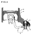
- Fig. 2 is a sectional view of an engine.
- Fig. 3 is a diagram for explaining an engine lubrication system of an automobile.
- Fig. 4 is a view of a recessed portion 23a illustrated in Fig. 1, viewed from B direction.
- Fig. 5 is a sectional view taken along line V-V of Fig. 1.
- Fig. 6 is a sectional view taken along line VI-VI of Fig. 1 in a condition where two recessed portions 23a are provided.
- Fig. 7 is a local sectional view of the pressure actuated valve according to the embodiment of the present invention in a condition where the valve is opened.
- oil engine lubricating oil (hereinafter oil) of an engine is stored in an oil pan 1, and the oil reaches an oil pump 3 through an oil strainer 2.
- the oil discharged to the main oil passage 6 is distributed into three systems, that is, a camshaft system I, a crankshaft system II, and a piston cooling system III. As illustrated in Fig. 3, the oil is returned to the oil pan 1 after lubricating and cooling each portion of each system.
- the pressure actuated valve 11 configures a part of a piston cooling apparatus 12 provided in the piston cooling system III.
- the piston cooling apparatus 12 is attached to a cylinder block 14 by means of a bolt 18.
- the cylinder block 14 is positioned lower than a bottom dead center of a piston 13.
- the piston cooling apparatus 12 sprays the oil, which is discharged from a nozzle 15 press-fitted and supported at a valve main body 21, toward a back side of the piston 13 for cooling.
- reference numeral 16 in Fig. 2 indicates a cylinder of the engine.
- the pressure actuated valve 11 includes the valve main body 21 having an inlet opening 28 and an outlet opening 26, a valve chamber 22 formed in the valve main body 21 between the inlet opening 28 and the outlet opening 26 and operatively connected thereto, a valve seat 23 press-fitted and fixed in the valve chamber 22, a spherical valve 24 seated on a valve seat opening 23b, which is provided at the valve seat 23, a coil spring 25 (i.e., biasing member) directly biases a back portion of the spherical valve 24, and a spring retainer 27 of the coil spring 25. Further, at the outlet opening 26, the nozzle 15 is press-fitted and supported with a predetermined posture and formed integrally with the valve main body 21.
- the inlet opening 28 of the pressure actuated valve 11 communicates with the main oil passage 6 illustrated in Fig. 2.
- the spherical valve 24 moves downward in response to the oil pressure and the flow of the oil as indicated by an arrow in Fig. 7 can be achieved.
- a recessed portion 23a (i.e., fluid pressure biasing means) illustrated in Figs. 4-5 is axially provided on a peripheral portion of an inside wall of the valve seat 23.
- the spherical valve 24 moves downward in response to the oil pressure, the oil flows into the valve chamber 22 through a circumferential space between the downwardly moved spherical valve 24 and the valve seat 23.
- a part where the recessed portion 23a is provided has a wider fluid passage of the oil compared to other parts, a large amount of oil flows at the part where the recessed portion 23a is provided.
- the spherical valve 24 moves in a direction opposite to the recessed portion 23a and pressed toward the inside wall portion of the valve seat 23 by means of a suppress force of the large amount of the oil.
- a direction of the biasing force of a biasing member toward the spherical valve is not necessarily be angled relative to a central line of the valve seat. Therefore, the spherical valve constantly receives the force from the direction perpendicular to the seal surface, and the spherical valve does not unevenly contact with the valve seat. Accordingly, the optimal sealability can be ensured.
- valve seat 23 provided with the recessed portion 23a is press-fitted and formed integrally with the valve main body 21.
- the invention is not limited thereto.
- the valve main body 21 may be directly formed with the recessed portion 23a and may be functioned as the valve seat 23.
- two recessed portions 23a may be provided as illustrated in Fig. 6. Further, alternatively, or in addition, plural recessed portions 23a may be provided and each recessed portion 23a may be positioned not symmetric with one another relative to an axial center of the valve seat.
- the shape of the recessed portion 23a is not limited to a U shape.
- a circular arc depression may be provided at a part of the inside wall of the valve chamber 22 for obtaining an identical effect as described above.
- the spherical valve because the fluid pressure in the valve chamber biases the spherical valve in a direction perpendicular to a fluid flow direction while opening of the spherical valve, the spherical valve does not come into the floating state while opening of the valve. Therefore, the oscillation of the fluid in the piping is not induced, and generation of the noise can thereby be prevented.
- the direction of the biasing force of the biasing member toward the spherical valve is not necessarily be angled relative to the central line of the valve seat. Therefore, the spherical valve constantly receives the force from the direction perpendicular to the seal surface, and the spherical valve does not unevenly contact with the valve seat. Accordingly, the optimal sealability can be ensured.
- the fluid pressure in the valve chamber biases the spherical valve in the direction perpendicular to the fluid flow direction.
- the invention is not limited thereto. Even in a condition where a direction of a resultant force of a biasing force is angled relative to the fluid flow direction, the present invention is applicable as long as the resultant force of the biasing force includes an element of a direction perpendicular to the fluid flow direction.
- the pressure actuated valve can generate the fluid pressure for biasing the spherical valve in the direction perpendicular to the fluid flow direction with a simple structure.
Landscapes
- Engineering & Computer Science (AREA)
- General Engineering & Computer Science (AREA)
- Mechanical Engineering (AREA)
- Chemical & Material Sciences (AREA)
- Combustion & Propulsion (AREA)
- Safety Valves (AREA)
- Details Of Valves (AREA)
- Lubrication Of Internal Combustion Engines (AREA)
- Check Valves (AREA)
Abstract
A pressure actuated valve (11) includes a valve main body (21), an inlet opening (28) provided at the valve main body, an outlet opening (26) provided at the valve main body, a valve chamber (22) formed in the valve main body between the inlet opening and the outlet opening and operatively connected thereto, a valve seat (23) provided at an end portion of the valve chamber at the inlet opening side, a spherical valve (24) detachably provided in the valve chamber at the valve seat, a biasing member (25) biasing the spherical valve in a direction in which the spherical valve is pressed toward the valve seat, and a fluid pressure biasing mechanism (23a) provided at the valve main body for biasing the spherical valve in a direction perpendicular to a fluid flow direction by means of the fluid pressure in the valve chamber while opening of the spherical valve.
Description
- This invention relates to a pressure actuated valve which allows flow of fluid in a first direction when a spherical valve, which is arranged to face a valve seat opening formed at a fluid passage, opens the valve seat opening, and prevents the flow of the fluid in a second direction when the spherical valve closes the valve seat opening.
- Conventionally, a pressure actuated valve includes a spherical valve, which is biased toward a valve seat by means of a coil spring by a predetermined force. In a condition where a pressure of fluid toward an inlet opening becomes larger degree than a biasing force of the coil spring, the pressure actuated valve is opened and the fluid is flowed into a valve chamber from the inlet opening. Then the fluid is supplied to a desirable portion from an outlet opening. In a condition where the pressure actuated valve is opened, the spherical valve comes into a floating state. In such circumstances, because of possible deviations in shape of the valve seat during production, the pressure actuated valve is oscillated caused by the flow of the fluid, and a liquid column of whole piping is oscillated because of an oscillation of the pressure actuated valve, and thus a noise may occasionally be generated. In order to prevent such noise, in a known pressure actuated valve disclosed in JPH08-006575B (see Fig. 1), a central line of the valve seat and a central axis line of the coil spring are shifted, and the spherical valve is biased by means of the coil spring toward the valve seat with an angle relative to the central line thereof. According to the disclosed pressure actuated valve, because the spherical valve is biased toward the valve seat or is biased toward one side of a peripheral wall leading from the valve seat by means of the biasing force of the coil spring, the spherical valve does not come into the floating state while opening of the valve. Therefore an oscillation of the fluid in the piping is not induced, and generation of the noise can be prevented.
- However, because the spherical valve constantly receives the force from an angled direction while opening of the valve, the spherical valve unevenly contacts with the valve seat, and the pressure actuated valve may occasionally fail to ensure an optimal sealability.
- A need thus exists for a pressure actuated valve, which prevents the generation of the noise because of the induced oscillation of the fluid in the piping, and prevents the spherical valve from unevenly contacting with the valve seat with a simple structure.
- According to an aspect of the present invention, a pressure actuated valve includes a valve main body, an inlet opening provided at the valve main body, an outlet opening provided at the valve main body, a valve chamber formed in the valve main body between the inlet opening and the outlet opening and operatively connected thereto, a valve seat provided at an end portion of the valve chamber at the inlet opening side, a spherical valve detachably provided in the valve chamber at the valve seat, the spherical valve being separated from the valve seat for opening the valve in response to a fluid pressure at the inlet opening, a biasing member biasing the spherical valve in a direction in which the spherical valve is pressed toward the valve seat, and a fluid pressure biasing means provided at the valve main body for biasing the spherical valve in a direction perpendicular to a fluid flow direction by means of the fluid pressure in the valve chamber while opening of the spherical valve.
- According to the present invention, because the fluid pressure in the valve chamber biases the spherical valve in a direction perpendicular to a fluid flow direction while opening of the spherical valve, the spherical valve does not come into the floating state while opening of the valve. Therefore, the oscillation of the fluid in the piping is not induced, and generation of the noise can thereby be prevented.
- According to the present invention, the direction of the biasing force of the biasing member toward the spherical valve is not necessarily be angled relative to the central line of the valve seat. Therefore, the spherical valve constantly receives the force from the direction perpendicular to the seal surface, and the spherical valve does not unevenly contact with the valve seat. Accordingly, the optimal sealability can be ensured.
- The foregoing and additional features and characteristics of the present invention will become more apparent from the following detailed description considered with reference to the accompanying drawings, wherein:
- Fig. 1 is a sectional view of a pressure actuated valve according to an embodiment of the present invention.
- Fig. 2 is a sectional view of an engine.
- Fig. 3 is a diagram for explaining an engine lubrication system of an automobile.
- Fig. 4 is a view of a
recessed portion 23a illustrated in Fig. 1, viewed from B direction. - Fig. 5 is a sectional view taken along line V-V of Fig. 1.
- Fig. 6 is a sectional view taken along line VI-VI of Fig. 1 in a condition where two recessed
portions 23a are provided. - Fig. 7 is a local sectional view of the pressure actuated valve according to the embodiment of the present invention in a condition where the valve is opened.
- An embodiment of the present invention applied to an engine lubrication system of an automobile will be explained hereinbelow.
- As illustrated in Fig. 3, engine lubricating oil (hereinafter oil) of an engine is stored in an
oil pan 1, and the oil reaches anoil pump 3 through anoil strainer 2. - After the oil supplied into the
oil pump 3 passes through an oil filter 4, the oil is cooled in anoil cooler 5 and discharged to amain oil passage 6. - The oil discharged to the
main oil passage 6 is distributed into three systems, that is, a camshaft system I, a crankshaft system II, and a piston cooling system III. As illustrated in Fig. 3, the oil is returned to theoil pan 1 after lubricating and cooling each portion of each system. - The pressure actuated
valve 11 according to the embodiment of the present invention configures a part of apiston cooling apparatus 12 provided in the piston cooling system III. - As illustrated in Fig. 2, the
piston cooling apparatus 12 is attached to a cylinder block 14 by means of abolt 18. The cylinder block 14 is positioned lower than a bottom dead center of apiston 13. Thepiston cooling apparatus 12 sprays the oil, which is discharged from anozzle 15 press-fitted and supported at a valvemain body 21, toward a back side of thepiston 13 for cooling. Further,reference numeral 16 in Fig. 2 indicates a cylinder of the engine. - As illustrated in Fig. 1, the pressure actuated
valve 11 includes the valvemain body 21 having an inlet opening 28 and an outlet opening 26, avalve chamber 22 formed in the valvemain body 21 between the inlet opening 28 and the outlet opening 26 and operatively connected thereto, avalve seat 23 press-fitted and fixed in thevalve chamber 22, aspherical valve 24 seated on a valve seat opening 23b, which is provided at thevalve seat 23, a coil spring 25 (i.e., biasing member) directly biases a back portion of thespherical valve 24, and aspring retainer 27 of thecoil spring 25. Further, at the outlet opening 26, thenozzle 15 is press-fitted and supported with a predetermined posture and formed integrally with the valvemain body 21. - The inlet opening 28 of the pressure actuated
valve 11 communicates with themain oil passage 6 illustrated in Fig. 2. In a condition where an oil pressure in themain oil passage 6 becomes larger degree than a biasing force of thecoil spring 25 toward thespherical valve 24, thespherical valve 24 moves downward in response to the oil pressure and the flow of the oil as indicated by an arrow in Fig. 7 can be achieved. - A recessed
portion 23a (i.e., fluid pressure biasing means) illustrated in Figs. 4-5 is axially provided on a peripheral portion of an inside wall of thevalve seat 23. - When the
spherical valve 24 moves downward in response to the oil pressure, the oil flows into thevalve chamber 22 through a circumferential space between the downwardly movedspherical valve 24 and thevalve seat 23. On this occasion, because a part where therecessed portion 23a is provided has a wider fluid passage of the oil compared to other parts, a large amount of oil flows at the part where therecessed portion 23a is provided. In consequence, thespherical valve 24 moves in a direction opposite to therecessed portion 23a and pressed toward the inside wall portion of thevalve seat 23 by means of a suppress force of the large amount of the oil. - As illustrated in Fig. 7, because the
spherical valve 24 is pressed toward one side of a peripheral wall of thevalve seat 23 by means of the suppress force of the oil, thespherical valve 24 does not come into a floating state while opening of the valve, and an oscillation of the oil in a piping does not induced, and generation of a noise is thereby prevented. - According to the embodiment of the present invention, a direction of the biasing force of a biasing member toward the spherical valve is not necessarily be angled relative to a central line of the valve seat. Therefore, the spherical valve constantly receives the force from the direction perpendicular to the seal surface, and the spherical valve does not unevenly contact with the valve seat. Accordingly, the optimal sealability can be ensured.
- According to the embodiment of the present invention, the
valve seat 23 provided with therecessed portion 23a is press-fitted and formed integrally with the valvemain body 21. However, the invention is not limited thereto. Alternatively, or in addition, the valvemain body 21 may be directly formed with therecessed portion 23a and may be functioned as thevalve seat 23. - Alternatively, or in addition, two
recessed portions 23a may be provided as illustrated in Fig. 6. Further, alternatively, or in addition, plural recessedportions 23a may be provided and eachrecessed portion 23a may be positioned not symmetric with one another relative to an axial center of the valve seat. - Moreover, the shape of the
recessed portion 23a is not limited to a U shape. Alternatively, or in addition, a circular arc depression may be provided at a part of the inside wall of thevalve chamber 22 for obtaining an identical effect as described above. - According to the embodiment of the present invention, because the fluid pressure in the valve chamber biases the spherical valve in a direction perpendicular to a fluid flow direction while opening of the spherical valve, the spherical valve does not come into the floating state while opening of the valve. Therefore, the oscillation of the fluid in the piping is not induced, and generation of the noise can thereby be prevented.
- According to the embodiment of the present invention, the direction of the biasing force of the biasing member toward the spherical valve is not necessarily be angled relative to the central line of the valve seat. Therefore, the spherical valve constantly receives the force from the direction perpendicular to the seal surface, and the spherical valve does not unevenly contact with the valve seat. Accordingly, the optimal sealability can be ensured.
- According to the embodiment of the present invention, it is mentioned that the fluid pressure in the valve chamber biases the spherical valve in the direction perpendicular to the fluid flow direction. However the invention is not limited thereto. Even in a condition where a direction of a resultant force of a biasing force is angled relative to the fluid flow direction, the present invention is applicable as long as the resultant force of the biasing force includes an element of a direction perpendicular to the fluid flow direction.
- According to the embodiment of the present invention, without increasing components, the pressure actuated valve can generate the fluid pressure for biasing the spherical valve in the direction perpendicular to the fluid flow direction with a simple structure.
It is explicitly stated that all features disclosed in the description and/or the claims are intended to be disclosed separately and independently from each other for the purpose of original disclosure as well as for the purpose of restricting the claimed invention independent of the composition of the features in the embodiments and/or the claims. It is explicitly stated that all value ranges or indications of groups of entities disclose every possible intermediate value or intermediate entity for the purpose of original disclosure as well as for the purpose of restricting the claimed invention, in particular as limits of value ranges.
Claims (5)
- A pressure actuated valve (11) comprising:a valve main body (21);an inlet opening (28) provided at the valve main body;an outlet opening (26) provided at the valve main body;a valve chamber (22) formed in the valve main body between the inlet opening and the outlet opening and operatively connected thereto;a valve seat (23) provided at an end portion of the valve chamber at the inlet opening side;a spherical valve (24) detachably provided in the valve chamber at the valve seat, the spherical valve being separated from the valve seat for opening the valve in response to a fluid pressure at the inlet opening;a biasing member (25) biasing the spherical valve in a direction in which the spherical valve is pressed toward the valve seat; anda fluid pressure biasing means (23 a) provided at the valve main body for biasing the spherical valve in a direction perpendicular to a fluid flow direction by means of the fluid pressure in the valve chamber while opening of the spherical valve.
- The pressure actuated valve according to claim 1, wherein
the fluid pressure biasing means includes a recessed portion (23a) formed at an inside wall of the valve chamber. - The pressure actuated valve according to claim 2, wherein
the recessed portion includes a single groove formed at the inside wall of the valve chamber and facing the spherical valve. - The pressure actuated valve according to claim 2, wherein
the recessed portion includes a plurality of grooves formed at the inside wall of the valve chamber and facing the spherical valve. - The pressure actuated valve according to claim 4, wherein
the plurality of grooves is formed at the inside wall of the valve chamber and each groove is positioned not symmetric with one another relative to an axial center of the valve seat.
Applications Claiming Priority (1)
| Application Number | Priority Date | Filing Date | Title |
|---|---|---|---|
| JP2005020523A JP2006207693A (en) | 2005-01-28 | 2005-01-28 | Pressure operated valve |
Publications (1)
| Publication Number | Publication Date |
|---|---|
| EP1686299A1 true EP1686299A1 (en) | 2006-08-02 |
Family
ID=36177900
Family Applications (1)
| Application Number | Title | Priority Date | Filing Date |
|---|---|---|---|
| EP20060000190 Withdrawn EP1686299A1 (en) | 2005-01-28 | 2006-01-05 | Pressure actuated valve |
Country Status (5)
| Country | Link |
|---|---|
| US (1) | US20060169332A1 (en) |
| EP (1) | EP1686299A1 (en) |
| JP (1) | JP2006207693A (en) |
| KR (1) | KR20060087403A (en) |
| CN (1) | CN1811249A (en) |
Cited By (1)
| Publication number | Priority date | Publication date | Assignee | Title |
|---|---|---|---|---|
| US10174854B2 (en) | 2015-11-16 | 2019-01-08 | Danfoss Power Solutions Aps | Hydraulic overpressure valve and hydraulic machine |
Families Citing this family (12)
| Publication number | Priority date | Publication date | Assignee | Title |
|---|---|---|---|---|
| JP2010071294A (en) * | 2007-01-11 | 2010-04-02 | Mitsuba Corp | Pressure control device |
| US8397749B2 (en) * | 2007-09-07 | 2013-03-19 | Metaldyne Company Llc | Piston cooling jet with tracking ball orifice |
| JP5323659B2 (en) * | 2009-12-04 | 2013-10-23 | 愛三工業株式会社 | Pressure regulating valve |
| CN104421465B (en) * | 2013-08-27 | 2017-09-22 | 吴炫隆 | Check (non-return) valve |
| JP2015074980A (en) * | 2013-10-04 | 2015-04-20 | 松本重工業株式会社 | Oil jet |
| US9383030B2 (en) * | 2013-12-18 | 2016-07-05 | Hsuan-Lung Wu | Check valve |
| CN104075002A (en) * | 2014-06-30 | 2014-10-01 | 无锡市威海达机械制造有限公司 | Adjustable ultrahigh pressure check valve |
| CN104075001A (en) * | 2014-06-30 | 2014-10-01 | 无锡市威海达机械制造有限公司 | Adjustable ultrahigh pressure check valve |
| CN108006266B (en) * | 2015-11-23 | 2019-08-13 | 邵作权 | Bi-bit bi-pass electromagnetism pressure maintaining valve |
| JP7269599B2 (en) * | 2019-04-08 | 2023-05-09 | マツダ株式会社 | engine cooling system |
| CN110542010B (en) * | 2019-09-09 | 2024-04-05 | 华南理工大学 | Oil filling port drip-proof device and oil filling device |
| US11506110B2 (en) * | 2020-05-18 | 2022-11-22 | Schaeffler Technologies AG & Co. KG | Oil-spray tube with poppet valve |
Citations (4)
| Publication number | Priority date | Publication date | Assignee | Title |
|---|---|---|---|---|
| GB191407068A (en) * | 1913-06-27 | 1915-04-22 | Paul Alexandre Savoye | Improvements in Auxiliary Air Admission Valves for Internal Combustion Engines. |
| JPS61256072A (en) * | 1985-05-10 | 1986-11-13 | Nec Corp | Valve element |
| JPH01188779A (en) * | 1988-01-25 | 1989-07-28 | Matsushita Electric Ind Co Ltd | Check valve for water heater |
| US20040007271A1 (en) * | 2002-06-01 | 2004-01-15 | Michael Kuehn | Check valve |
Family Cites Families (2)
| Publication number | Priority date | Publication date | Assignee | Title |
|---|---|---|---|---|
| BE793082A (en) * | 1971-12-20 | 1973-04-16 | Gen Electric | DOSING VALVE FOR ADJUSTING THE FLOW OF CONTAMINATED FLUIDS |
| DE19525948A1 (en) * | 1995-07-17 | 1997-01-23 | Schaeffler Waelzlager Kg | Step valve |
-
2005
- 2005-01-28 JP JP2005020523A patent/JP2006207693A/en active Pending
- 2005-12-30 KR KR1020050135729A patent/KR20060087403A/en not_active Withdrawn
-
2006
- 2006-01-03 US US11/322,279 patent/US20060169332A1/en not_active Abandoned
- 2006-01-05 EP EP20060000190 patent/EP1686299A1/en not_active Withdrawn
- 2006-01-20 CN CNA2006100064456A patent/CN1811249A/en active Pending
Patent Citations (4)
| Publication number | Priority date | Publication date | Assignee | Title |
|---|---|---|---|---|
| GB191407068A (en) * | 1913-06-27 | 1915-04-22 | Paul Alexandre Savoye | Improvements in Auxiliary Air Admission Valves for Internal Combustion Engines. |
| JPS61256072A (en) * | 1985-05-10 | 1986-11-13 | Nec Corp | Valve element |
| JPH01188779A (en) * | 1988-01-25 | 1989-07-28 | Matsushita Electric Ind Co Ltd | Check valve for water heater |
| US20040007271A1 (en) * | 2002-06-01 | 2004-01-15 | Michael Kuehn | Check valve |
Non-Patent Citations (2)
| Title |
|---|
| PATENT ABSTRACTS OF JAPAN vol. 011, no. 111 (M - 578) 8 April 1987 (1987-04-08) * |
| PATENT ABSTRACTS OF JAPAN vol. 013, no. 477 (M - 885) 27 October 1989 (1989-10-27) * |
Cited By (1)
| Publication number | Priority date | Publication date | Assignee | Title |
|---|---|---|---|---|
| US10174854B2 (en) | 2015-11-16 | 2019-01-08 | Danfoss Power Solutions Aps | Hydraulic overpressure valve and hydraulic machine |
Also Published As
| Publication number | Publication date |
|---|---|
| US20060169332A1 (en) | 2006-08-03 |
| JP2006207693A (en) | 2006-08-10 |
| KR20060087403A (en) | 2006-08-02 |
| CN1811249A (en) | 2006-08-02 |
Similar Documents
| Publication | Publication Date | Title |
|---|---|---|
| JP3787508B2 (en) | High pressure fuel supply pump | |
| US20040052664A1 (en) | High-pressure fuel feed pump | |
| US20060169332A1 (en) | Pressure actuated valve | |
| JP5800020B2 (en) | Fuel pump | |
| US6019071A (en) | Engine windage tray | |
| US20110110807A1 (en) | High-pressure pump | |
| WO2013035132A1 (en) | Fuel pump, and fuel supply system for internal combustion engine | |
| CN111480000B (en) | Fuel supply pump | |
| JP6940569B2 (en) | High pressure fuel pump | |
| JP2012207632A (en) | High pressure pump | |
| CN101793178A (en) | Oil supplying device | |
| CN105121831A (en) | Piston pump, in particular high-pressure fuel pump | |
| CN108290094A (en) | Cartridges and filters for oil filters in cars | |
| JP2006317002A (en) | Slide bearing | |
| JP2023519559A (en) | fuel high pressure pump | |
| KR102299585B1 (en) | Piston pump, particularly fuel pump for a fuel system for an internal combustion engine | |
| JP6527066B2 (en) | High pressure fuel supply pump | |
| EP3943777B1 (en) | Chain tensioner | |
| WO2018164023A1 (en) | High-pressure pump | |
| JP2006291904A5 (en) | ||
| JP2007231959A (en) | High pressure fuel supply pump | |
| JP4484828B2 (en) | High pressure fuel supply pump | |
| JP4372817B2 (en) | High pressure fuel supply pump | |
| JP7269599B2 (en) | engine cooling system | |
| JPH08233133A (en) | Check valve |
Legal Events
| Date | Code | Title | Description |
|---|---|---|---|
| PUAI | Public reference made under article 153(3) epc to a published international application that has entered the european phase |
Free format text: ORIGINAL CODE: 0009012 |
|
| AK | Designated contracting states |
Kind code of ref document: A1 Designated state(s): AT BE BG CH CY CZ DE DK EE ES FI FR GB GR HU IE IS IT LI LT LU LV MC NL PL PT RO SE SI SK TR |
|
| AX | Request for extension of the european patent |
Extension state: AL BA HR MK YU |
|
| AKX | Designation fees paid | ||
| STAA | Information on the status of an ep patent application or granted ep patent |
Free format text: STATUS: THE APPLICATION IS DEEMED TO BE WITHDRAWN |
|
| 18D | Application deemed to be withdrawn |
Effective date: 20070203 |
|
| REG | Reference to a national code |
Ref country code: DE Ref legal event code: 8566 |