EP1686233A1 - Echelle escamotable multifonctionnelle - Google Patents
Echelle escamotable multifonctionnelle Download PDFInfo
- Publication number
- EP1686233A1 EP1686233A1 EP05002007A EP05002007A EP1686233A1 EP 1686233 A1 EP1686233 A1 EP 1686233A1 EP 05002007 A EP05002007 A EP 05002007A EP 05002007 A EP05002007 A EP 05002007A EP 1686233 A1 EP1686233 A1 EP 1686233A1
- Authority
- EP
- European Patent Office
- Prior art keywords
- ladder
- collapsible
- section
- sections
- legs
- Prior art date
- Legal status (The legal status is an assumption and is not a legal conclusion. Google has not performed a legal analysis and makes no representation as to the accuracy of the status listed.)
- Withdrawn
Links
Images


Classifications
-
- E—FIXED CONSTRUCTIONS
- E06—DOORS, WINDOWS, SHUTTERS, OR ROLLER BLINDS IN GENERAL; LADDERS
- E06C—LADDERS
- E06C1/00—Ladders in general
- E06C1/02—Ladders in general with rigid longitudinal member or members
- E06C1/14—Ladders capable of standing by themselves
- E06C1/16—Ladders capable of standing by themselves with hinged struts which rest on the ground
- E06C1/20—Ladders capable of standing by themselves with hinged struts which rest on the ground with supporting struts formed as poles
- E06C1/22—Ladders capable of standing by themselves with hinged struts which rest on the ground with supporting struts formed as poles with extensible, e.g. telescopic, ladder parts or struts
-
- E—FIXED CONSTRUCTIONS
- E06—DOORS, WINDOWS, SHUTTERS, OR ROLLER BLINDS IN GENERAL; LADDERS
- E06C—LADDERS
- E06C1/00—Ladders in general
- E06C1/02—Ladders in general with rigid longitudinal member or members
- E06C1/04—Ladders for resting against objects, e.g. walls poles, trees
- E06C1/08—Ladders for resting against objects, e.g. walls poles, trees multi-part
- E06C1/12—Ladders for resting against objects, e.g. walls poles, trees multi-part extensible, e.g. telescopic
- E06C1/125—Ladders for resting against objects, e.g. walls poles, trees multi-part extensible, e.g. telescopic with tubular longitudinal members nested within each other
-
- E—FIXED CONSTRUCTIONS
- E06—DOORS, WINDOWS, SHUTTERS, OR ROLLER BLINDS IN GENERAL; LADDERS
- E06C—LADDERS
- E06C1/00—Ladders in general
- E06C1/02—Ladders in general with rigid longitudinal member or members
- E06C1/14—Ladders capable of standing by themselves
- E06C1/16—Ladders capable of standing by themselves with hinged struts which rest on the ground
- E06C1/18—Ladders capable of standing by themselves with hinged struts which rest on the ground with supporting struts formed as ladders
Definitions
- the present invention relates to a collapsible stepladder provided with ladder sections being telescopically inserted in each other.
- stepladders Collapsible and expandable stepladders are known in the art. Below examples of prior art are stepladders described.
- a telescopically collapsible stepladder comprising two legs that are hinged to one another.
- Each leg is formed of telescopically collapsible sections having latch mechanisms in each of the rungs for automatically locking the sections relative to one another when the leg is extended.
- the latch mechanisms in each rung are designed to release the next higher section when the rung is collapsed against the next lower rung.
- the separation of the rungs of one of the legs, when the stepladder is extended, is greater than the separation of the rungs in the other leg.
- stepladder of WO-A1-99/51848 The problem with the stepladder of WO-A1-99/51848 is that the collapsible sections of the two legs have different height, which is why the stepladder will never pass type approval. Further, the stepladder can not be converted to a straight ladder, since folding the two legs to be adjacent, results in a ladder with many small steps due to the different height of collapsible sections.
- a ladder including two hinged sections that can be oriented in an inverted V-configuration for use as a stepladder, or in a straight linear configuration for use as a straight ladder.
- Each section of the ladder includes a number of U-shaped support units, each of which defines a crossbar and two downwardly extending side rails.
- the side rails of the different U-shaped units are of graduated cross sectional dimensions, so that the units can be contracted together by telescopically sliding the aligned side rails within one another.
- the problem with the ladder of US-A-4 989 692 is that the two sections of the ladder can not be used without an external support or the user will need to balance while working, which is not preferable from a work safety aspect.
- GB-A-2 110 286 another stepladder is disclosed, including a first set of strong and telescopic elements, a second set of parts, each comprising a support surface forming one step of the ladder. Each part is transversely connected to one element or group of strong elements of the first set.
- a set of stopper studs and locking means between the various strong elements of the first set is arranged to ensure at least the stability of the two extreme positions of the ladder, that is, of the ladder folded up on itself and of the extended ladder.
- the ladder of GB-A-2 110 286 not only suffers from the same problems as US-A-4 989 692, but also lacks a locking or fixing arrangement in the converted disposition.
- the object of the present invention is to overcome the disadvantages and problems with the prior art step ladders and to provide a stepladder which is easy and safe to handle and which is possible to convert into a straight ladder without lowering the standards of safety and manageability.
- a stepladder according to the characterizing features of claim 1 solves the above problem.
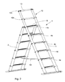
- FIG. 1 shows a collapsible stepladder 1 comprising a first ladder leg 2, which is hingedly connected to a second ladder leg 3 in the upper ends of the first and second ladder leg 2, 3 by a hinge connection 5.
- Each of the ladder legs 2, 3 comprise several ladder sections 4a-4d, where each ladder section 4a-4d comprises two ladder bars 6, 7, arranged parallel to each other and interconnected at one end by a rung 8 to form a U-shaped ladder section 4a-4d.
- the ladder sections 4a-4d are telescopically inserted into a lower ladder section to form a collapsible ladder leg 2, 3.
- the ladder legs 2, 3 further comprise a lower ladder section 4e, which comprises two ladder bars 6, 7, arranged parallel to each other and interconnected at a upper end by a rung 9, at a lower end by a ladder base 10 and in between the rung 9 and the ladder base 10 by another rung 11.
- the ladder sections 4a-4d are telescopically inserted into the ladder section 4e.
- the ladder legs 2,3 should comprise at least three ladder sections 4a-4e, but in a preferred embodiment four collapsible ladder sections 4a-4d are arranged together with the lower ladder section 4e.
- the number of ladder sections is limited by the stability of the stepladder and the requirement to pass type approval.
- Each rung 8, 9 comprises a retaining mechanism for automatically locking the ladder sections relative to one another when the ladder legs 2,3 are extended.
- the retaining mechanism could be any kind previously known in the art, e.g. any of the retaining mechanisms shown in EP-B1-0 527 766 or EP-A1-1 402 143.
- the second ladder leg 3 is provided with a support part 12 in one end.
- the support part 12 is telescopically extendible from the second ladder leg 3 to form a ladder extension 12 of the ladder leg 3, and the support part 12 projects above the hinge connection 5 between the two ladder legs 2, 3.
- the support part 12 comprise at least one support section 12a-12b, each support section comprising two ladder bars 6, 7 arranged parallel to each other and interconnected at one end by a rung 16 to form at least one U-shaped support section 12a-12b.
- the support sections 12a-12b are telescopically inserted into the ladder leg 3 to form a collapsible support part 12.
- the support part 12 also comprises an upper support section 12c, comprising two ladder bars 6, 7, arranged parallel to each other and interconnected at one end by a rung 13 to form a U-shaped support section 12c.
- the support section 12c is telescopically inserted into the lower support section 12a-12b.
- the ladder is shown, having both ladder legs 2, 3 and the support or extension part 12 fully extended.
- the support part 12 enables the user of the stepladder to stand on the upper ladder section 4a-4b as the support part 12 makes the user feel safe.
- the support part 12 comprises two collapsible ladder sections 12a and 12c.
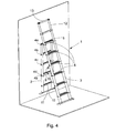
- a device for holding tools or objects such as a tray, a table, a shelf, a box/case or a basket, can be arranged.
- the device is clamped, squeezed, hanged, hooked or in any other suitable manner arranged to be positioned at the upper rung 13.
- the rung 13 might be arranged with receiving means such as holes, chamfered surfaces, recesses or the like to better receive the holding device.
- a strap 14 is also shown arranged between the ladder legs 2, 3 to increase the stability of the ladder in the extended and folded mode and to prevent the ladder legs from splaying apart.
- the strap 14 is attached by suit fastening means, e.g. a pop rivet or the like, in one end to a rear side of a rung 8 of the ladder leg 2 and in another end to a rear side of a rung 8 of the ladder leg 3.
- the strap 14 is attached to the rungs 8 positioned on ladder section 4e of the ladder legs 2, 3, respectively, but it would also be possible to attach the strap 14 to rungs associated with ladder sections located above or below ladder sections 4e.
- the strap 14 is also shown in Figs. 3 and 5, but has been omitted in Figs. 1 and 4 for clarity reasons.
- the strap 14 can be made of nylon woven nylon material.
- Fig. 3 is shown how the hinge connection 5 almost creates a platform between the upper part of the ladder legs 2, 3, that can be used for placing a toolbox or the like or to stand on.
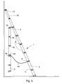
- Figs. 4 and 5 the ladder section 4d of the ladder leg 2 is collapsed.
- the stepladder 1 is converted to a straight ladder, which is positioned against a wall.
- the support part 12 enables the ladder to be leaned against the wall without the ladder leg 2 interfering or instabilizing the ladder in the leaned position. Since the ladder section 4d of the ladder leg 2 is collapsed, the ladder leg 2 is hanging freely and out of the way when the ladder is converted to a straight ladder. Any or several of the collapsible ladder sections 4a-4d can be collapsed.
- a holding means 15 holds the collapsed ladder sections and the ladder section positioned adjacently below the collapsed ladder sections together.
- the holding means is a strap 15 of a nylon material, but it can also be a hook, which is attached to the rung of one ladder section and which can be pivoted so that the hook part is surrounds the rung of an adjacently positioned ladder section. It is also possible to use a U-shaped clamp of a plastic material, which holds the rungs of the collapsed ladder sections and the ladder section positioned adjacently below the collapsed ladder sections together.
- the advantage with a clamp is that any of the ladder sections 4a-4d can be collapsed and held my the clamp, whereas the location of a hook or a strap decides which collapsible ladder sections 4a-4d should be collapsed and held together with the ladder section positioned adjacently below the collapsed ladder section.
- the retaining mechanism or more the specifically the locking pins of the retaining mechanism can be used to hold or lock a collapsed collapsible ladder sections 4a-4d in relation to a ladder section positioned adjacently below the collapsed ladder section 4a-4d.
- the ladder section 4d is collapsed and the strap 15, i.e. the holding means, surrounds the collapsed ladder section 4d and the ladder section 4e of the ladder leg 2.
- the strap 15 is preferably attached to one of the rungs 8, 9 and being long enough to surround the rungs of the collapsed ladder sections and the rung of the ladder section positioned adjacently below the collapsed ladder sections.
- the strap 15 is attached to rung 9 by a pop rivet or any other suitable fastening means.
- the strap 15 is fastened by the center of the strap 15 so that the strap extends substantially equally in both directions from the fastening position.
- Velcro ⁇ fasteners or similar fastening means are provided that interacts with each other when the strap ends surround the rungs.
- the ladder sections 4b-4e of the ladder leg 3 are suitably designed with deeper rungs 8, 9, 11 (see Figs. 3 and 5) to provide an extra foot support compared with the rungs of the ladder sections of the ladder leg 2.
- the rungs are suitably made of an extruded aluminum profile.
- At least one collapsible ladder section 4a-4d of the first ladder leg 2 is collapsed to enable the ladder to be used as a straight ladder.
- the holding means 15 can in that case be used to maintain the two ladder legs 2, 3 in the adjacent and parallel position.
- the lower ladder section 4e of the second ladder leg 3 could in that case be longer than the lower ladder section 4e of the first ladder leg 2 so that both lower end parts of the two ladder legs 2, 3 are supported by the ground at the same time.
Priority Applications (9)
| Application Number | Priority Date | Filing Date | Title |
|---|---|---|---|
| EP05002007A EP1686233A1 (fr) | 2005-02-01 | 2005-02-01 | Echelle escamotable multifonctionnelle |
| PCT/EP2006/000856 WO2006082032A1 (fr) | 2005-02-01 | 2006-02-01 | Echelle transformable pliante |
| AU2006210078A AU2006210078A1 (en) | 2005-02-01 | 2006-02-01 | Collapsible combination ladder |
| CNA2006800037673A CN101111658A (zh) | 2005-02-01 | 2006-02-01 | 可折叠复合梯 |
| NZ556606A NZ556606A (en) | 2005-02-01 | 2006-02-01 | Collapsible combination ladder with telescopic legs one ladder section having wider steps than the other |
| CA002594804A CA2594804A1 (fr) | 2005-02-01 | 2006-02-01 | Echelle transformable pliante |
| EA200701641A EA012890B1 (ru) | 2005-02-01 | 2006-02-01 | Складная комбинированная лестница |
| JP2007552599A JP2008528834A (ja) | 2005-02-01 | 2006-02-01 | 折畳み式組合せ梯子 |
| NO20074352A NO20074352L (no) | 2005-02-01 | 2007-08-27 | Collapsible combination ladder |
Applications Claiming Priority (1)
| Application Number | Priority Date | Filing Date | Title |
|---|---|---|---|
| EP05002007A EP1686233A1 (fr) | 2005-02-01 | 2005-02-01 | Echelle escamotable multifonctionnelle |
Publications (1)
| Publication Number | Publication Date |
|---|---|
| EP1686233A1 true EP1686233A1 (fr) | 2006-08-02 |
Family
ID=34933538
Family Applications (1)
| Application Number | Title | Priority Date | Filing Date |
|---|---|---|---|
| EP05002007A Withdrawn EP1686233A1 (fr) | 2005-02-01 | 2005-02-01 | Echelle escamotable multifonctionnelle |
Country Status (9)
| Country | Link |
|---|---|
| EP (1) | EP1686233A1 (fr) |
| JP (1) | JP2008528834A (fr) |
| CN (1) | CN101111658A (fr) |
| AU (1) | AU2006210078A1 (fr) |
| CA (1) | CA2594804A1 (fr) |
| EA (1) | EA012890B1 (fr) |
| NO (1) | NO20074352L (fr) |
| NZ (1) | NZ556606A (fr) |
| WO (1) | WO2006082032A1 (fr) |
Cited By (6)
| Publication number | Priority date | Publication date | Assignee | Title |
|---|---|---|---|---|
| WO2008052433A1 (fr) * | 2006-10-31 | 2008-05-08 | Zhengping Su | Structure de raccordement pour échelles |
| CN105221058A (zh) * | 2015-09-16 | 2016-01-06 | 国网辽宁省电力有限公司锦州供电公司 | 变电站室内分节绝缘梯 |
| CN105332644A (zh) * | 2015-11-23 | 2016-02-17 | 乐山市同源科技有限公司 | 多功能梯 |
| US10480211B2 (en) | 2013-12-04 | 2019-11-19 | Nondrill Pty Ltd | Handrail assembly, system and method of installation |
| NL2029224B1 (en) | 2021-09-22 | 2023-03-29 | Lampe Holding Bv | Portable ladder with a stand off device |
| SE545153C2 (en) * | 2021-12-16 | 2023-04-18 | Telesteps Ab | Collapsible step ladder and a connection bracket therefor |
Families Citing this family (11)
| Publication number | Priority date | Publication date | Assignee | Title |
|---|---|---|---|---|
| US8225906B2 (en) | 2008-08-22 | 2012-07-24 | Core Distribution, Inc. | Extendable/retractable ladder |
| US10233692B2 (en) | 2014-12-02 | 2019-03-19 | Core Distribution, Inc. | Foldable ladder |
| RU2635150C2 (ru) * | 2015-10-09 | 2017-11-09 | Общество с ограниченной ответственностью"Инвестпроект" | Фиксирующее устройство для удлиняющейся лестницы |
| KR101767014B1 (ko) * | 2016-11-02 | 2017-08-09 | 서동영 | 전동 드라이버로 길이 조절이 가능한 자동 사다리 |
| US11174678B2 (en) | 2017-11-08 | 2021-11-16 | Core Distribution, Inc. | Locking assembly for a telescoping ladder |
| CN108049798A (zh) * | 2017-12-15 | 2018-05-18 | 潘跃进 | 单边伸缩梯后支撑架 |
| RU2679762C2 (ru) * | 2018-05-07 | 2019-02-12 | Александр Михайлович Гультяев | Лестница с ящиками |
| CN108868569A (zh) * | 2018-05-22 | 2018-11-23 | 苏州盈腾五金制品有限公司 | 一种消防用便携式伸缩爬梯 |
| US11795760B2 (en) | 2019-10-24 | 2023-10-24 | Core Distribution, Inc. | Ladder tripod assembly and system |
| RU199345U1 (ru) * | 2020-06-24 | 2020-08-28 | Общество с ограниченной ответственностью «ТЦ Телекоммонтаж» | Складная лестница |
| RU210209U1 (ru) * | 2021-10-06 | 2022-03-31 | Сергей Анатольевич Денисенко | Лестничная секция |
Citations (5)
| Publication number | Priority date | Publication date | Assignee | Title |
|---|---|---|---|---|
| US2127949A (en) * | 1936-05-08 | 1938-08-23 | Zeman Paul | Folding ladder |
| FR2435596A1 (fr) * | 1978-07-24 | 1980-04-04 | Gubri Sa Ets L | Dispositif pour la limitation de l'ecartement et du developpement des plans d'une echelle transformable |
| GB2110286A (en) | 1981-05-08 | 1983-06-15 | Bier And Son I | Light and extensible ladder |
| US4989692A (en) | 1989-06-16 | 1991-02-05 | Min Liaw S | Multi-purpose extendable and retractable ladder |
| WO1999051848A1 (fr) | 1998-04-04 | 1999-10-14 | Eriksson, Per-Olof | Escabeau repliable |
Family Cites Families (1)
| Publication number | Priority date | Publication date | Assignee | Title |
|---|---|---|---|---|
| JPS5045451Y2 (fr) * | 1971-06-29 | 1975-12-23 |
-
2005
- 2005-02-01 EP EP05002007A patent/EP1686233A1/fr not_active Withdrawn
-
2006
- 2006-02-01 CN CNA2006800037673A patent/CN101111658A/zh active Pending
- 2006-02-01 NZ NZ556606A patent/NZ556606A/en not_active IP Right Cessation
- 2006-02-01 WO PCT/EP2006/000856 patent/WO2006082032A1/fr not_active Application Discontinuation
- 2006-02-01 JP JP2007552599A patent/JP2008528834A/ja active Pending
- 2006-02-01 CA CA002594804A patent/CA2594804A1/fr not_active Abandoned
- 2006-02-01 AU AU2006210078A patent/AU2006210078A1/en not_active Abandoned
- 2006-02-01 EA EA200701641A patent/EA012890B1/ru unknown
-
2007
- 2007-08-27 NO NO20074352A patent/NO20074352L/no not_active Application Discontinuation
Patent Citations (5)
| Publication number | Priority date | Publication date | Assignee | Title |
|---|---|---|---|---|
| US2127949A (en) * | 1936-05-08 | 1938-08-23 | Zeman Paul | Folding ladder |
| FR2435596A1 (fr) * | 1978-07-24 | 1980-04-04 | Gubri Sa Ets L | Dispositif pour la limitation de l'ecartement et du developpement des plans d'une echelle transformable |
| GB2110286A (en) | 1981-05-08 | 1983-06-15 | Bier And Son I | Light and extensible ladder |
| US4989692A (en) | 1989-06-16 | 1991-02-05 | Min Liaw S | Multi-purpose extendable and retractable ladder |
| WO1999051848A1 (fr) | 1998-04-04 | 1999-10-14 | Eriksson, Per-Olof | Escabeau repliable |
Cited By (9)
| Publication number | Priority date | Publication date | Assignee | Title |
|---|---|---|---|---|
| WO2008052433A1 (fr) * | 2006-10-31 | 2008-05-08 | Zhengping Su | Structure de raccordement pour échelles |
| US10480211B2 (en) | 2013-12-04 | 2019-11-19 | Nondrill Pty Ltd | Handrail assembly, system and method of installation |
| CN105221058A (zh) * | 2015-09-16 | 2016-01-06 | 国网辽宁省电力有限公司锦州供电公司 | 变电站室内分节绝缘梯 |
| CN105332644A (zh) * | 2015-11-23 | 2016-02-17 | 乐山市同源科技有限公司 | 多功能梯 |
| NL2029224B1 (en) | 2021-09-22 | 2023-03-29 | Lampe Holding Bv | Portable ladder with a stand off device |
| WO2023046760A1 (fr) | 2021-09-22 | 2023-03-30 | Lampe Holding B.V. | Échelle portable comportant un dispositif de recul |
| SE545153C2 (en) * | 2021-12-16 | 2023-04-18 | Telesteps Ab | Collapsible step ladder and a connection bracket therefor |
| SE2151545A1 (en) * | 2021-12-16 | 2023-04-18 | Telesteps Ab | Collapsible step ladder and a connection bracket therefor |
| WO2023113684A1 (fr) * | 2021-12-16 | 2023-06-22 | Telesteps Ab | Escabeau pliant et support de raccordement s'y rapportant |
Also Published As
| Publication number | Publication date |
|---|---|
| AU2006210078A1 (en) | 2006-08-10 |
| EA012890B1 (ru) | 2009-12-30 |
| NZ556606A (en) | 2011-01-28 |
| CA2594804A1 (fr) | 2006-08-10 |
| NO20074352L (no) | 2007-10-28 |
| WO2006082032A1 (fr) | 2006-08-10 |
| EA200701641A1 (ru) | 2008-02-28 |
| JP2008528834A (ja) | 2008-07-31 |
| CN101111658A (zh) | 2008-01-23 |
Similar Documents
| Publication | Publication Date | Title |
|---|---|---|
| EP1686233A1 (fr) | Echelle escamotable multifonctionnelle | |
| US20080164097A1 (en) | Collapsible Combination Ladder | |
| US20200270945A1 (en) | Stepladder adapted for use as a single ladder or an extension ladder | |
| DK2260170T3 (en) | Ladder | |
| US7967111B2 (en) | Stepladder | |
| US20210246725A1 (en) | Stepladder tray | |
| US11578533B2 (en) | Step ladder device allowing the user to stand and work safely and comfortably on the upper steps of a step ladder | |
| US20040134714A1 (en) | Ladder stabilizers | |
| US6457559B1 (en) | Foldable ladder | |
| KR100937838B1 (ko) | 절첩 가능한 계단식 사다리 | |
| US20040031646A1 (en) | Fire escape ladder | |
| EP1500754A2 (fr) | Améliorations d'une ou concernant une plate-forme d'accès | |
| KR20060110136A (ko) | 사다리 | |
| KR102371325B1 (ko) | 접철식 사다리, a자형 접철식 사다리, 우마형 접철식 사다리 | |
| IES20050206A2 (en) | Combined stepladder and platform | |
| SE2151545A1 (en) | Collapsible step ladder and a connection bracket therefor | |
| WO2001038681A1 (fr) | Echelle pliable | |
| WO2023046760A1 (fr) | Échelle portable comportant un dispositif de recul | |
| CA1176610A (fr) | Marche et stabilisateur d'echelle | |
| JPH0882177A (ja) | 脚立用道具掛止具及び脚立 | |
| CA2288437A1 (fr) | Echarpe pour echelles extensibles | |
| JPH08246776A (ja) | 梯 子 | |
| GB2410525A (en) | Platform attachment for a stepladder | |
| IE20050206U1 (en) | Combined stepladder and platform |
Legal Events
| Date | Code | Title | Description |
|---|---|---|---|
| PUAI | Public reference made under article 153(3) epc to a published international application that has entered the european phase |
Free format text: ORIGINAL CODE: 0009012 |
|
| AK | Designated contracting states |
Kind code of ref document: A1 Designated state(s): AT BE BG CH CY CZ DE DK EE ES FI FR GB GR HU IE IS IT LI LT LU MC NL PL PT RO SE SI SK TR |
|
| AX | Request for extension of the european patent |
Extension state: AL BA HR LV MK YU |
|
| 17P | Request for examination filed |
Effective date: 20070117 |
|
| AKX | Designation fees paid |
Designated state(s): AT BE BG CH CY CZ DE DK EE ES FI FR GB GR HU IE IS IT LI LT LU MC NL PL PT RO SE SI SK TR |
|
| AXX | Extension fees paid |
Extension state: LV Payment date: 20070117 |
|
| 17Q | First examination report despatched |
Effective date: 20090304 |
|
| STAA | Information on the status of an ep patent application or granted ep patent |
Free format text: STATUS: THE APPLICATION IS DEEMED TO BE WITHDRAWN |
|
| 18D | Application deemed to be withdrawn |
Effective date: 20151030 |