EP1686205A1 - Layering unit for carded webs and method for layering said webs by means of said layering unit. - Google Patents
Layering unit for carded webs and method for layering said webs by means of said layering unit. Download PDFInfo
- Publication number
- EP1686205A1 EP1686205A1 EP05106993A EP05106993A EP1686205A1 EP 1686205 A1 EP1686205 A1 EP 1686205A1 EP 05106993 A EP05106993 A EP 05106993A EP 05106993 A EP05106993 A EP 05106993A EP 1686205 A1 EP1686205 A1 EP 1686205A1
- Authority
- EP
- European Patent Office
- Prior art keywords
- retriever
- carriage
- distributor
- cylinder
- conveyor belt
- Prior art date
- Legal status (The legal status is an assumption and is not a legal conclusion. Google has not performed a legal analysis and makes no representation as to the accuracy of the status listed.)
- Granted
Links
- 238000000034 method Methods 0.000 title claims description 15
- 238000004804 winding Methods 0.000 claims description 10
- 230000008901 benefit Effects 0.000 description 12
- 238000004519 manufacturing process Methods 0.000 description 10
- 238000010276 construction Methods 0.000 description 4
- 238000005192 partition Methods 0.000 description 4
- 238000006073 displacement reaction Methods 0.000 description 3
- 230000008569 process Effects 0.000 description 3
- 238000007665 sagging Methods 0.000 description 3
- 230000001133 acceleration Effects 0.000 description 2
- 230000008859 change Effects 0.000 description 2
- 238000010586 diagram Methods 0.000 description 2
- 239000000835 fiber Substances 0.000 description 2
- 239000000463 material Substances 0.000 description 2
- 230000009467 reduction Effects 0.000 description 2
- 229920000049 Carbon (fiber) Polymers 0.000 description 1
- 229910000831 Steel Inorganic materials 0.000 description 1
- 239000004917 carbon fiber Substances 0.000 description 1
- 239000007795 chemical reaction product Substances 0.000 description 1
- 238000000151 deposition Methods 0.000 description 1
- 238000009826 distribution Methods 0.000 description 1
- 230000006872 improvement Effects 0.000 description 1
- 239000003562 lightweight material Substances 0.000 description 1
- 239000004745 nonwoven fabric Substances 0.000 description 1
- 239000000047 product Substances 0.000 description 1
- 230000001681 protective effect Effects 0.000 description 1
- 238000004080 punching Methods 0.000 description 1
- 239000010421 standard material Substances 0.000 description 1
- 239000010959 steel Substances 0.000 description 1
- 230000001360 synchronised effect Effects 0.000 description 1
- 239000004753 textile Substances 0.000 description 1
Images


Classifications
-
- D—TEXTILES; PAPER
- D01—NATURAL OR MAN-MADE THREADS OR FIBRES; SPINNING
- D01G—PRELIMINARY TREATMENT OF FIBRES, e.g. FOR SPINNING
- D01G25/00—Lap-forming devices not integral with machines specified above
-
- D—TEXTILES; PAPER
- D04—BRAIDING; LACE-MAKING; KNITTING; TRIMMINGS; NON-WOVEN FABRICS
- D04H—MAKING TEXTILE FABRICS, e.g. FROM FIBRES OR FILAMENTARY MATERIAL; FABRICS MADE BY SUCH PROCESSES OR APPARATUS, e.g. FELTS, NON-WOVEN FABRICS; COTTON-WOOL; WADDING ; NON-WOVEN FABRICS FROM STAPLE FIBRES, FILAMENTS OR YARNS, BONDED WITH AT LEAST ONE WEB-LIKE MATERIAL DURING THEIR CONSOLIDATION
- D04H1/00—Non-woven fabrics formed wholly or mainly of staple fibres or like relatively short fibres
- D04H1/70—Non-woven fabrics formed wholly or mainly of staple fibres or like relatively short fibres characterised by the method of forming fleeces or layers, e.g. reorientation of fibres
- D04H1/74—Non-woven fabrics formed wholly or mainly of staple fibres or like relatively short fibres characterised by the method of forming fleeces or layers, e.g. reorientation of fibres the fibres being orientated, e.g. in parallel (anisotropic fleeces)
Definitions
- the present invention relates to a layering unit for carded webs delivered by a feed unit and to a method for layering said carded webs by means of said layering unit.
- nonwovens It is common knowledge that the process for obtaining sheets of nonwoven textiles, generally known simply as nonwovens, consists in placing a web of carded fibers in several overlapping layers in order to obtain a multilayer of the required thickness, which is subsequently bonded together by means of a needle punching procedure or other suitable methods.
- a first problem consists in the fact that it is difficult to obtain a uniform thickness because the depositing movement needs to be done at a constant speed and this is not easy to achieve because the layering is done using a reciprocating motion.
- Another difficulty stems from the intrinsically fragile nature of the web, which is easily damaged, especially as a result of the air turbulence induced by the rate of displacement of the layering unit's moving parts.
- horizontal layering machines have been developed, such as the one described in the Patent IT1213836, which has two conveyor belts wrapped around revolving cylinders, and where at least two carriages can be identified, i.e. a main retriever carriage and a distributor carriage.
- Another drawback stems from the need to add a pair of separator belts between the layering unit and the layered web in order to protect the latter from the further turbulence generated by the operation of the layering unit.
- layering units such as the one described in the Patent application WO 00/56960, which comprises a distributor carriage and three retriever carriages, two of which are situated underneath the layering unit.
- a second drawback again due to the high working speed, lies in that it is impossible to reduce the ruptures in the carded web to lower levels than those obtainable using layering devices of the previously-described type.
- a third drawback lies in that the layering unit demands a kinematically complex architecture and is consequently costly to manufacture in mechanical terms.
- the object of the present invention is to overcome all the above-listed drawbacks typical of the machines deriving from the known state of the art.
- the first object of the present invention is to produce a unit for layering carded webs that enables high rates of production while nonetheless retaining a lesser complexity of construction than the layering devices belonging to the known state of the art.
- Another object of the invention is to produce a unit for layering carded webs that, by comparison with equivalent layering units deriving from the known state of the art, features fewer strains in its component parts.
- a further object of the invention is to produce a unit for layering carded webs that enables the use of structural parts (e.g. the revolving cylinders) made of conventional materials.
- Yet another object of the present invention is to produce a unit for layering carded webs that protects the web from the turbulence generated by the layering unit's kinematics without the need to add separator belts or partitions between the web and the machine.
- a unit for layering carded webs delivered by a feed unit that, in accordance with the details given in the main claim, comprises:
- the retriever carriages and distributor carriage move along a path parallel to the stacking table and, as they proceed, the retriever carriages always move in the same direction as the distributor carriage.
- the layering unit of the invention has at least a part of the first conveyor belt lying between the distributor carriage and the first retriever carriage and at least a part of the second conveyor belt lying between the distributor carriage and the second retriever carriage, said sections of belt moving in directions substantially coinciding with each other and parallel to the stacking table.
- a method for layering carded webs delivered by a feed unit in a layering unit of the type comprising:
- the sections of the first and second conveyor belts coming between said carriages and the distributor carriage will always be of limited length, and always shorter than in equivalent layering machines made according to the known state of the art.
- Another advantage lies in that, because these sections of belt are always of limited length, they run no risk of sagging onto the layered web, which can sometimes damage the end product.
- a further advantage lies in that the movement of the retriever carriages and distributor carriage in the same direction and in the same sense enables the cylinders to turn at lower angular velocities and angular accelerations, and consequently with a lower inertia - for the same production rate - than in layering machines made according to the known state of the art.
- Yet another advantage lies in the straightforward kinematics of the layering unit according to the invention, which means a less complex construction than for layering units made according to the known state of the art and, as a consequence, a lower cost of manufacture and a greater reliability.
- the unit for layering carded webs V delivered by a feed unit, forming the object of the present invention is schematically illustrated in fig. 1, where it is globally indicated by the numeral 1.
- the unit comprises a first conveyor belt 2 and a second conveyor belt 3, that are each arranged so as to turn a closed loop and with at least a part of one belt coming over and under the other so as to form a substantially "U" shaped section 4 .
- the shaped section 4 creates a channel 5 for guiding the web V , complete with an inlet 6 and an outlet 7.
- the conveyor belts 2, 3 are wound around a plurality of revolving cylinders 8 that ensure their forward feed and tensioning.
- a stacking table 9 is provided underneath the conveyor belts 2, 3, for collecting the web V, arranged in layers F .
- first retriever carriage 10 a second retriever carriage 13 and a distributor carriage 15.
- the first retriever carriage 10 includes a structure supporting a first retriever cylinder 11 for the first conveyor belt 2 and the second conveyor belt 3, coinciding with the bottom 4a of the U-shaped section 4, and a pair of second retriever cylinders 12 for the first conveyor belt 2.
- the second retriever carriage 13 comprises a structure supporting a retriever cylinder 14 for the second conveyor belt 3.
- the distributor carriage 15 includes a structure supporting a first winding distributor cylinder 16 for the first conveyor belt 2 and a pair of second winding distributor cylinders 17 for the second conveyor belt 3, said first and second distributor cylinders 16, 17 forming the outlet 7 from the web-guiding channel 5 .
- the distributor carriage 15 is situated in between the retriever carriages 10, 13.
- the retriever carriages 10, 13 and the distributor carriage 15 move along a path X parallel to the stacking table 9 and, when in motion, said retriever carriages 10, 13 always move in the same direction as the distributor carriage 15.
- the first conveyor belt 2 has a section 20 coming between the distributor carriage 15 and the first retriever carriage 10; to be more precise, as shown in fig. 1, said section 20 comes between the first distributor cylinder 16 in the distributor carriage 15 and the pair of second retriever cylinders 12 in the first retriever carriage 10.
- the second conveyor belt 3 has a section 21 coming between the distributor carriage 15 and the second retriever carriage 13; to be more precise, said section 21 comes between the pair of second distributor cylinders 17 forming part of the distributor carriage 15 and the retriever cylinder 14 forming part of the second retriever carriage 13.
- Said sections 20, 21 of the first conveyor belt 2 and second conveyor belt 3 follow a path Y parallel to the stacking table 9 and form a surface that separates the inside of the layering unit 1 from the web V arranged in layers F.
- Fig. 1 also shows that the web-guiding channel 5 has a section 22 following a path Z leading to the stacking table 9 containing the layered web V.
- Said section 22 slopes downwards and is needed to bring the web V from the feed area 18 to the distributor carriage 15.
- the first retriever carriage 110 comprises a first retriever half-carriage 130, that includes the first retriever cylinder 111, and a second retriever half-carriage 131 that includes the pair of second retriever cylinders 112.
- the section 120 of the first conveyor belt 102 comes between the distributor carriage 115 and the second retriever carriage 131, the latter being positioned alongside the first half-carriage 130 on the side opposite the distributor carriage 115.
- the carded web V, delivered by the feed unit is laid on the second conveyor belt 3, which, in moving forward, carries the web inside the guiding channel 5 through the inlet 6.
- the web V is protected by the first conveyor belt 2 extending above it.
- the web V covers the descending section 22 of the guiding channel 5 , reversing the direction in which it travels when it reaches the bottom 4a of the U-shaped section 4 and finally coming up to the distributor carriage 15, from where it exits in a vertical direction, through the outlet 7, to become arranged in layers F on the stacking table 9.
- the sequence of figures from 3a to 3c shows a succession of moments in the working cycle of the layering unit 1 according to the invention, specifically showing that the first retriever carriage 10 and the second retriever carriage 13 move along the same path X and in the same direction due to the movement of the distributor carriage 15.
- Said movement in the same direction of the retriever carriages 10, 13 and of the distributor carriage 15 offers the advantage that the acceleration of the cylinders, when they change direction in the normal layering procedure, is lower than in equivalent layering machines made according to the known state of the art, wherein the retriever carriages are either fixed or they have a reciprocating motion with respect to the distributor carriage.
- retriever carriages 10, 13 are distinctive in that they have the same rate of displacement, so that the distance between them remains constant.
- the mobility of the first retriever carriage 10 also means that the descending section 22 of the web-guiding channel 5 has a gradient that varies with the movement of the first retriever carriage 10 and is always less than the gradient of the corresponding descending section of similar layering machines made according to the known state of the art.
- the descending section of the layering unit according to the present invention carries a lower risk of damaging the web than the corresponding descending sections of known layering units.
- the distributor carriage 115 and the second retriever half-carriage 131 are still decelerating, the latter with a more accentuated deceleration than the distributor carriage 115.
- the distributor carriage 115 accelerates less than the second retriever carriage 113 or the first retriever half-carriage 130.
- the second retriever half-carriage 131 together with the distributor carriage 115, performs a relative movement, with respect to the first retriever half-carriage 130 and to the second retriever carriage 113, that creates a sort of magazine for the conveyor belts 102, 103 and for the web V .
- said kinematic devices are eliminated in the embodiment described herein by dividing the first retriever carriage 110 into two retriever half-carriages 130, 131 so as to create the aforesaid magazine.
- the section 140 of the web-guiding channel 105 is extended by a length L1-L2, thus taking up the extra web.
- the distributor carriage 115 and the second retriever half-carriage 131 move on again, while the second retriever carriage 113 and the first retriever half-carriage 130 are still not moving, the distributor carriage 115 accelerates less than the second retriever half-carriage 131.
- the second retriever half-carriage 131 together with the distributor carriage 115, performs a relative movement, with respect to the first retriever half-carriage 130 and to the second retriever carriage 113, that again creates a sort of magazine for the conveyor belts 102, 103 and for the web V.
- the unit for layering carded web according the present invention achieves all the established objects.
- the unit for layering carded webs according to the present invention achieves the object of enabling a high rate of production while retaining a low rate of rotation of the cylinders forming part of said carriages.
- the invention achieves the object of ensuring that cylinders made of steel or other standard materials can be installed in the layering unit, which is not the case of layering units of known type, because of the high speeds involved.
- the unit for layering carded webs according to the present invention also achieves the object of being particularly reliable, thanks to its global structural simplicity.
- the unit for layering carded webs according to the present invention achieves the object of enabling high processing speeds while nonetheless retaining a lesser complexity of construction than layering machines made according to the known state of the art.
- the unit for layering carded webs according to the present invention also achieves the object of not submitting any of its components to severe stresses and thereby causing their failure.
- the unit for layering carded webs achieves the object of protecting the web from the turbulence generated by the kinematics of the layering unit without the need to add separator belts or partitions between the web and the machine.
- the unit for layering carded webs according to the present invention may be modified and further embodiments may be developed that will still be protected by the present patent, provided that they come within the concept of the present invention, even if they are not illustrated in the drawings or described herein.
Landscapes
- Engineering & Computer Science (AREA)
- Textile Engineering (AREA)
- Preliminary Treatment Of Fibers (AREA)
- Collation Of Sheets And Webs (AREA)
- Nonwoven Fabrics (AREA)
- Folding Of Thin Sheet-Like Materials, Special Discharging Devices, And Others (AREA)
- Treatment Of Fiber Materials (AREA)
- Organic Low-Molecular-Weight Compounds And Preparation Thereof (AREA)
Abstract
Description
- The present invention relates to a layering unit for carded webs delivered by a feed unit and to a method for layering said carded webs by means of said layering unit.
- It is common knowledge that the process for obtaining sheets of nonwoven textiles, generally known simply as nonwovens, consists in placing a web of carded fibers in several overlapping layers in order to obtain a multilayer of the required thickness, which is subsequently bonded together by means of a needle punching procedure or other suitable methods.
- It is also common knowledge that implementing such a layering process poses some difficulties, due both to the intrinsic features of the carded fiber web and to difficulties intrinsic in the layering process.
- To be more precise, a first problem consists in the fact that it is difficult to obtain a uniform thickness because the depositing movement needs to be done at a constant speed and this is not easy to achieve because the layering is done using a reciprocating motion.
- Another difficulty stems from the intrinsically fragile nature of the web, which is easily damaged, especially as a result of the air turbulence induced by the rate of displacement of the layering unit's moving parts.
- Since industrial-scale production demands a combination of rapid production times and good quality, layering machines have to be suitably studied to combine a high rate of production with the contrasting goal of a uniform, defect-free product.
- With a view to achieving said objectives, horizontal layering machines have been developed, such as the one described in the Patent IT1213836, which has two conveyor belts wrapped around revolving cylinders, and where at least two carriages can be identified, i.e. a main retriever carriage and a distributor carriage.
- Although these layering machines overcome the previously-mentioned practical difficulties, they also pose certain acknowledged drawbacks.
- One of these drawbacks is that, though they achieve a good production rate, this is still not sufficient to meet market demands.
- Said production rate cannot be further increased because of the presence of the two pressure and distribution cylinders lying in contact with the web leaving the distributor carriage, which are needed to ensure the smooth layering of the web. Any increase in working speed would make these cylinders create a turbulence that would suffice to damage the layered web.
- Another drawback stems from the need to add a pair of separator belts between the layering unit and the layered web in order to protect the latter from the further turbulence generated by the operation of the layering unit.
- To overcome the speed restriction, there are known layering units, such as the one described in the Patent application WO 00/56960, which comprises a distributor carriage and three retriever carriages, two of which are situated underneath the layering unit.
- Though it enables higher working speeds than the previously-described solution, this latter type of layering machine has other drawbacks.
- One of these drawbacks stems from the fact that the high working speed obliges the revolving cylinders to accelerate to such a degree that cylinders made of lightweight materials, such as carbon fibers, have to be used.
- A second drawback, again due to the high working speed, lies in that it is impossible to reduce the ruptures in the carded web to lower levels than those obtainable using layering devices of the previously-described type.
- A third drawback lies in that the layering unit demands a kinematically complex architecture and is consequently costly to manufacture in mechanical terms.
- Yet another drawback, due to the above-mentioned kinematic complexity, lies in that the layering unit carries a high risk of failure of its component parts.
- The object of the present invention is to overcome all the above-listed drawbacks typical of the machines deriving from the known state of the art.
- In particular, the first object of the present invention is to produce a unit for layering carded webs that enables high rates of production while nonetheless retaining a lesser complexity of construction than the layering devices belonging to the known state of the art.
- Another object of the invention is to produce a unit for layering carded webs that, by comparison with equivalent layering units deriving from the known state of the art, features fewer strains in its component parts.
- A further object of the invention is to produce a unit for layering carded webs that enables the use of structural parts (e.g. the revolving cylinders) made of conventional materials.
- Yet another object of the present invention is to produce a unit for layering carded webs that protects the web from the turbulence generated by the layering unit's kinematics without the need to add separator belts or partitions between the web and the machine.
- The aforementioned objects are achieved by a unit for layering carded webs delivered by a feed unit that, in accordance with the details given in the main claim, comprises:
- at least one first conveyor belt and at least one second conveyor belt, both arranged so as to turn in a closed loop, with at least a part of one belt coming over and under the other so as to form a substantially "U" shape and thereby create a channel for guiding said web, with an inlet and an outlet;
- a plurality of revolving cylinders on which said conveyor belts are wound and suitable for ensuring their forward feed and tensioning;
- a stacking table situated underneath said conveyor belts and suitable for collecting said web arranged in layers;
- at least one first retriever carriage comprising a structure supporting at least one retriever cylinder for said first and said second conveyor belts, in line with the bottom of said U-shaped part and at least one second retriever cylinder for said first conveyor belt;
- at least one second retriever carriage comprising a structure supporting at least one retriever cylinder for said second conveyor belt;
- at least one distributor carriage comprising a structure supporting at least one first winding distributor cylinder for said first conveyor belt, and at least a second winding distributor cylinder for said second conveyor belt, said first and second distributor cylinders forming said outlet from said guiding channel,
- According to the preferred embodiment of the invention, the retriever carriages and distributor carriage move along a path parallel to the stacking table and, as they proceed, the retriever carriages always move in the same direction as the distributor carriage.
- There is a constant distance between the first retriever cylinder forming part of the first retriever carriage and the retriever cylinder forming part of the second retriever carriage.
- The layering unit of the invention has at least a part of the first conveyor belt lying between the distributor carriage and the first retriever carriage and at least a part of the second conveyor belt lying between the distributor carriage and the second retriever carriage, said sections of belt moving in directions substantially coinciding with each other and parallel to the stacking table.
- The previously-mentioned objects are also achieved by a method for layering carded webs delivered by a feed unit in a layering unit of the type comprising:
- at least one first conveyor belt and at least one second conveyor belt, both arranged so as to turn in a closed loop, with at least a part of one belt coming over and under the other so as to form a substantially "U" shape and thereby create a channel for guiding said web, with an inlet and an outlet;
- a plurality of revolving cylinders on which said conveyor belts are wound and suitable for ensuring their forward feed and tensioning;
- a stacking table situated underneath said conveyor belts and suitable for collecting said web arranged in layers;
- at least one first retriever carriage comprising a structure supporting at least one retriever cylinder for said first and said second conveyor belts, in line with the bottom of said U-shaped part and at least one second retriever cylinder for said first conveyor belt;
- at least one second retriever carriage comprising a structure supporting at least one retriever cylinder for said second conveyor belt;
- at least one distributor carriage comprising a structure supporting at least one first winding distributor cylinder for said first conveyor belt, and at least a second winding distributor cylinder for said second conveyor belt, said first and second distributor cylinders forming said outlet from said guiding channel,
- Advantageously, since the distance between the first retriever carriage and the second retriever carriage is constant, the sections of the first and second conveyor belts coming between said carriages and the distributor carriage will always be of limited length, and always shorter than in equivalent layering machines made according to the known state of the art.
- Also advantageously, since these sections of conveyor belt protect the layered web from the air turbulence generated by the layering unit, it is unnecessary to add any partitions between the layering unit and the layered web.
- Another advantage lies in that, because these sections of belt are always of limited length, they run no risk of sagging onto the layered web, which can sometimes damage the end product.
- A further advantage lies in that the movement of the retriever carriages and distributor carriage in the same direction and in the same sense enables the cylinders to turn at lower angular velocities and angular accelerations, and consequently with a lower inertia - for the same production rate - than in layering machines made according to the known state of the art.
- Yet another advantage lies in the straightforward kinematics of the layering unit according to the invention, which means a less complex construction than for layering units made according to the known state of the art and, as a consequence, a lower cost of manufacture and a greater reliability.
- The aforesaid objects and advantages are better illustrated in the description of preferred embodiments of the invention, which are provided as non-restrictive examples with reference to the attached drawings, wherein:
- fig. 1 is a schematic diagram of the layering unit according to the invention;
- fig. 2 is a schematic diagram of one embodiment of the layering unit according to the invention;
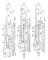
- figs. from 3a to 3c show a working sequence of the layering unit according to the invention;
- figs. from 4a to 4c show a working sequence of an embodiment of the layering unit according to the invention.
- The unit for layering carded webs V delivered by a feed unit, forming the object of the present invention, is schematically illustrated in fig. 1, where it is globally indicated by the numeral 1.
- The unit comprises a
first conveyor belt 2 and a second conveyor belt 3, that are each arranged so as to turn a closed loop and with at least a part of one belt coming over and under the other so as to form a substantially "U" shaped section 4. - The shaped section 4 creates a
channel 5 for guiding the web V, complete with aninlet 6 and an outlet 7. - The
conveyor belts 2, 3 are wound around a plurality of revolvingcylinders 8 that ensure their forward feed and tensioning. - A stacking table 9 is provided underneath the
conveyor belts 2, 3, for collecting the web V, arranged in layers F. - These layers are created by a
first retriever carriage 10, asecond retriever carriage 13 and adistributor carriage 15. - The
first retriever carriage 10 includes a structure supporting afirst retriever cylinder 11 for thefirst conveyor belt 2 and the second conveyor belt 3, coinciding with thebottom 4a of the U-shaped section 4, and a pair ofsecond retriever cylinders 12 for thefirst conveyor belt 2. - The
second retriever carriage 13 comprises a structure supporting aretriever cylinder 14 for the second conveyor belt 3. - The
distributor carriage 15 includes a structure supporting a firstwinding distributor cylinder 16 for thefirst conveyor belt 2 and a pair of secondwinding distributor cylinders 17 for the second conveyor belt 3, said first andsecond distributor cylinders channel 5. - According to the invention, the
distributor carriage 15 is situated in between theretriever carriages - According to the preferred embodiment of the invention, the
retriever carriages distributor carriage 15 move along a path X parallel to the stacking table 9 and, when in motion, saidretriever carriages distributor carriage 15. - There is a constant distance separating the
first retriever cylinder 11 forming part of thefirst retriever carriage 10, and theretriever cylinder 14 forming part of thesecond retriever carriage 13. - The
first conveyor belt 2 has asection 20 coming between thedistributor carriage 15 and thefirst retriever carriage 10; to be more precise, as shown in fig. 1, saidsection 20 comes between thefirst distributor cylinder 16 in thedistributor carriage 15 and the pair ofsecond retriever cylinders 12 in thefirst retriever carriage 10. - Similarly, the second conveyor belt 3 has a
section 21 coming between thedistributor carriage 15 and thesecond retriever carriage 13; to be more precise, saidsection 21 comes between the pair ofsecond distributor cylinders 17 forming part of thedistributor carriage 15 and theretriever cylinder 14 forming part of thesecond retriever carriage 13. - Said
sections first conveyor belt 2 and second conveyor belt 3 follow a path Y parallel to the stacking table 9 and form a surface that separates the inside of the layering unit 1 from the web V arranged in layers F. - This has the advantage of separating the layering unit 1 from the web V arranged in layers F, thereby protecting the latter from the turbulence generated by the movements of the layering unit 1, with no need to add any further protective partitions.
- Fig. 1 also shows that the web-guiding
channel 5 has asection 22 following a path Z leading to the stacking table 9 containing the layered web V. -
Said section 22 slopes downwards and is needed to bring the web V from thefeed area 18 to thedistributor carriage 15. - The movement of the
retriever carriages distributor carriage 15 is assured by means of two distinct motors, which are electronically synchronized by means of an electronic control unit. - This offers the advantage of avoiding the need to use mechanical drive shafts, thus further reducing the inertia in the layering unit.
- It also carries the advantages of a further improvement in the performance and reduction in the complexity of the servicing needs for the layering unit according to the invention.
- According to one embodiment, illustrated in fig. 2 and globally indicated by the numeral 100, the
first retriever carriage 110 comprises a first retriever half-carriage 130, that includes thefirst retriever cylinder 111, and a second retriever half-carriage 131 that includes the pair ofsecond retriever cylinders 112. - In this embodiment, the
section 120 of thefirst conveyor belt 102 comes between thedistributor carriage 115 and thesecond retriever carriage 131, the latter being positioned alongside the first half-carriage 130 on the side opposite thedistributor carriage 115. - In operating terms, the carded web V, delivered by the feed unit is laid on the second conveyor belt 3, which, in moving forward, carries the web inside the guiding
channel 5 through theinlet 6. - As it moves along inside the guiding
channel 5, the web V is protected by thefirst conveyor belt 2 extending above it. - As the
conveyor belts 2, 3 move forward, the web V covers the descendingsection 22 of the guidingchannel 5, reversing the direction in which it travels when it reaches the bottom 4a of the U-shaped section 4 and finally coming up to thedistributor carriage 15, from where it exits in a vertical direction, through the outlet 7, to become arranged in layers F on the stacking table 9. - The sequence of figures from 3a to 3c shows a succession of moments in the working cycle of the layering unit 1 according to the invention, specifically showing that the
first retriever carriage 10 and thesecond retriever carriage 13 move along the same path X and in the same direction due to the movement of thedistributor carriage 15. - Said movement in the same direction of the
retriever carriages distributor carriage 15 offers the advantage that the acceleration of the cylinders, when they change direction in the normal layering procedure, is lower than in equivalent layering machines made according to the known state of the art, wherein the retriever carriages are either fixed or they have a reciprocating motion with respect to the distributor carriage. - This enables a reduction in the inertia, and consequently allows for the use of conventional materials for the construction of the component parts of the layering unit 1.
- In addition, the
retriever carriages - This means that the distances between said
retriever carriages distributor carriage 15 remain limited, since the latter has a higher rate of displacement. - This is due particularly to the fact that the
distributor carriage 15 is always situated in between the tworetriever carriages - As a result, there is the particular advantage that the
sections conveyor belts 2, 3 are always short and the risk of their sagging, which could damage the web V being arranged in layers F is thus avoided. - Moreover, there is the advantage that, for the same risk of sagging, longer layers of web can be obtained.
- The mobility of the
first retriever carriage 10 also means that the descendingsection 22 of the web-guidingchannel 5 has a gradient that varies with the movement of thefirst retriever carriage 10 and is always less than the gradient of the corresponding descending section of similar layering machines made according to the known state of the art. - Since the gradient of the descending sections is one of the causes of web damage, this means there is the advantage that the descending section of the layering unit according to the present invention carries a lower risk of damaging the web than the corresponding descending sections of known layering units.
- As for the embodiment involving the division of the
first retriever carriage 110 into two half-carriages - The point on the right-hand side where the direction of movement is reversed is shown in the operating sequence shown in figs. from 4a to 4c.
- According to the preferred embodiment described herein, at this reversing point, when the first retriever half-
carriage 130 and thesecond retriever carriage 113 stop, thedistributor carriage 115 and the second retriever half-carriage 131 are still decelerating, the latter with a more accentuated deceleration than thedistributor carriage 115. - When the
distributor carriage 115, thesecond retriever carriage 113 and the first retriever half-carriage 130 move on, while the second retriever half-carriage 131 remains at a standstill, thedistributor carriage 115 accelerates less than thesecond retriever carriage 113 or the first retriever half-carriage 130. - As a result, at the point where the direction is reversed, the second retriever half-
carriage 131, together with thedistributor carriage 115, performs a relative movement, with respect to the first retriever half-carriage 130 and to thesecond retriever carriage 113, that creates a sort of magazine for theconveyor belts - In fact, we know that the
conveyor belts carriages - Said situation poses a risk of the web piling up and this is generally prevented by adding kinematic devices of known type.
- To further reduce the structural complexity and increase the productivity of the layering unit according to the present invention by comparison with known layering units, said kinematic devices are eliminated in the embodiment described herein by dividing the
first retriever carriage 110 into two retriever half-carriages - In fact, as shown in the operating sequence illustrated in figs. 4a to 4c, when the direction of movement is reversed, the distance L1 between the first retriever half-
carriage 130 and the second retriever half-carriage 131 is shortened until it reaches the distance L2. - At the same time, the
section 140 of the web-guidingchannel 105 is extended by a length L1-L2, thus taking up the extra web. - Once the direction has changed, said extra web is released.
- At the second point where the direction changes, i.e. on the left-hand side, the sequence is repeated in the same way.
- To be more precise, when the second retriever half-
carriage 131 stops, thedistributor carriage 115, the first retriever half-carriage 130 and thesecond retriever carriage 113 are still decelerating, since the latter have a more accentuated deceleration than thedistributor carriage 115. - When the
distributor carriage 115 and the second retriever half-carriage 131 move on again, while thesecond retriever carriage 113 and the first retriever half-carriage 130 are still not moving, thedistributor carriage 115 accelerates less than the second retriever half-carriage 131. - Here again, therefore, at the point where the direction changes, the second retriever half-
carriage 131, together with thedistributor carriage 115, performs a relative movement, with respect to the first retriever half-carriage 130 and to thesecond retriever carriage 113, that again creates a sort of magazine for theconveyor belts - The above movements are described simply as a non-restrictive example.
- In fact, various operating sequences can be used, all of which share the feature of achieving a relative movement between the two half-carriages, together with the distributor carriage and the second retriever carriage, so as to create a virtual magazine between the half-carriages and the distributor carriage.
- In the light of the above, the unit for layering carded web according the present invention achieves all the established objects.
- In particular, thanks to the movement of the first and second retriever carriages, the unit for layering carded webs according to the present invention achieves the object of enabling a high rate of production while retaining a low rate of rotation of the cylinders forming part of said carriages.
- This means that the invention achieves the object of ensuring that cylinders made of steel or other standard materials can be installed in the layering unit, which is not the case of layering units of known type, because of the high speeds involved.
- The unit for layering carded webs according to the present invention also achieves the object of being particularly reliable, thanks to its global structural simplicity.
- To be more precise, the unit for layering carded webs according to the present invention achieves the object of enabling high processing speeds while nonetheless retaining a lesser complexity of construction than layering machines made according to the known state of the art.
- Thanks to its low inertia and simplified kinematics, the unit for layering carded webs according to the present invention also achieves the object of not submitting any of its components to severe stresses and thereby causing their failure.
- Finally, thanks to the sections of the two conveyor belts coming between the layering unit and the layered web, the unit for layering carded webs according to the present invention achieves the object of protecting the web from the turbulence generated by the kinematics of the layering unit without the need to add separator belts or partitions between the web and the machine.
- In the industrial engineering stage, the unit for layering carded webs according to the present invention may be modified and further embodiments may be developed that will still be protected by the present patent, provided that they come within the concept of the present invention, even if they are not illustrated in the drawings or described herein.
Claims (17)
- Layering unit (1; 100) for carded webs (V) delivered by a feed unit, of the type comprising:- at least one first conveyor belt (2; 102) and at least one second conveyor belt (3; 103), both arranged so as to turn in a closed loop, with at least a part of one belt coming over and under the other so as to form a substantially "U" shape (4; 104) and thereby creating a channel (5; 105) for guiding said web (V) with an inlet (6; 106) and an outlet (7; 107);- a plurality of revolving cylinders (8; 108), whereon said conveyor belts (2, 3; 102, 103) are wound and suitable for ensuring their forward feed and tensioning;- a stacking table (9; 109) placed underneath said conveyor belts (2, 3; 102, 103) and suitable for collecting said web (V) arranged in layers (F);- at least one first retriever carriage (10; 110) comprising a structure supporting at least one first retriever cylinder (11; 111) for said first and said second conveyor belts (2, 3; 102, 103), in line with the bottom (4a; 104a) of said U-shaped section (4; 104), and at least one second retriever cylinder (12; 112) for said first conveyor belt (2; 102);- at least one second retriever carriage (13; 113) comprising a structure supporting at least one retriever cylinder (14; 114) for said second conveyor belt (3; 103);- at least one distributor carriage (15; 115) comprising a structure supporting at least one first winding distributor cylinder (16; 116) for said first conveyor belt (2; 102) and at least one second winding distributor cylinder (17; 117) for said second conveyor belt (3; 103), said first and second distributor cylinders (16, 17; 116, 117) forming said outlet (7; 107) from said web-guiding channel (5; 105),characterized in that said distributor carriage (15; 115) is situated in between said at least one first retriever carriage (10; 110) and said at least one second retriever carriage (13; 113).
- Layering unit (1; 100) as in claim 1) characterized in that said retriever carriages (10, 13; 110, 113) and said distributor carriage (15; 115) move along a path (X) parallel to said stacking table (9; 109), said retriever carriages (10, 13; 110, 113) always moving in the same direction as said distributor carriage (15; 115).
- Layering unit (1; 100) as in claim 2) characterized in that it has a plurality of motors suitable for driving said retriever carriages (10, 13; 110, 113) and said distributor carriage (15; 115) along said path (X).
- Layering unit (1) as in claim 1) characterized in that there is a constant distance between said first retriever cylinder (11) forming part of said first retriever carriage (10) and said retriever cylinder (14) forming part of said second retriever carriage (13).
- Layering unit (1) as in claim 1) characterized in that said first conveyor belt (2) has at least a section (20) coming between said distributor carriage (15) and said first retriever carriage (10), and in that said second conveyor belt (3) has at least a section (21) coming between said distributor carriage (15) and said second retriever carriage (13).
- Layering unit (100) as in claim 1) characterized in that said first retriever carriage (110) is composed of a first retriever half-carriage (130) including at least said first retriever cylinder (111), and a second retriever half-carriage (131), including at least said second retriever cylinder (112).
- Layering unit (100) as in claim 6) characterized in that said first and second retriever half-carriages (130, 131) are placed side by side, said first retriever half-carriage (130) being situated in between said second retriever half-carriage (131) and said distributor carriage (115).
- Layering unit (100) as in claim 6) characterized in that said first conveyor belt (102) has at least a section (120) coming between said distributor carriage (115) and said second retriever half-carriage (131), and in that said second conveyor belt (103) has at least a section (121) coming between said distributor carriage (115) and said second retriever carriage (113).
- Layering unit (1; 100) as in claim 5) or 8) characterized in that said sections (20, 21; 120, 121) of said first conveyor belt (2; 102) and said second conveyor belt (3; 103) follow paths (Y) substantially parallel to said stacking table (9; 109).
- Layering unit (1; 100) as in claim 1) characterized in that said web-guiding channel (5; 105) has at least a section (22; 122) on a gradient (Z) leading to said stacking table (9).
- Method for layering carded webs (V) delivered by a feed unit to a layering unit (1; 100) of the type comprising:- at least one first conveyor belt (2; 102) and at least one second conveyor belt (3; 103), both arranged so as to turn in a closed loop, with at least a part of one belt coming over and under the other so as to form a substantially "U" shape (4; 104) and thereby creating a channel (5; 105) for guiding said web (V) with an inlet (6; 106) and an outlet (7; 107);- a plurality of revolving cylinders (8; 108), whereon said conveyor belts (2, 3; 102, 103) are wound and suitable for ensuring their forward feed and tensioning;- a stacking table (9; 109) placed underneath said conveyor belts (2, 3; 102, 103) and suitable for collecting said web (V) arranged in layers (F);- at least one first retriever carriage (10; 110) comprising a structure supporting at least one first retriever cylinder (11; 111) for said first and said second conveyor belts (2, 3; 102, 103), in line with the bottom (4a; 104a) of said U-shaped section (4; 104), and at least one second retriever cylinder (12; 112) for said first conveyor belt (2; 102);- at least one second retriever carriage (13; 113) comprising a structure supporting at least one retriever cylinder (14; 114) for said second conveyor belt (3; 103);- at least one distributor carriage (15; 115) comprising a structure supporting at least one first winding distributor cylinder (16; 116) for said first conveyor belt (2; 102) and at least one second winding distributor cylinder (17; 117) for said second conveyor belt (3; 103), said first and second distributor cylinders (16, 17; 116, 117) forming said outlet (7; 107) from said web-guiding channel (5; 105),characterized in that said retriever carriages (10, 13; 110, 113) and said distributor carriage (15; 115) move along a path (X) parallel to said stacking table (9; 109) and always in the same direction.
- Method as in claim 11) characterized in that said distributor carriage (15; 115) is situated in between said at least one first retriever carriage (10; 110) and said at least one second retriever carriage (13; 113).
- Method as in claim 11) characterized in that the speed variations along said path (X) of said first retriever cylinder (11; 111) in said first retriever carriage (10; 110) are always the same as the speed variations along said path (X) of said retriever cylinder (14; 114) in said second retriever carriage (13; 113).
- Method as in claim 11) characterized in that the speed variations along said path (X) of said first retriever cylinder (11; 111) in said first retriever carriage (10; 110) and of said retriever cylinder (14; 114) in said second retriever carriage (13; 113) are greater than the speed variations along said path (X) of said distributor carriage (15; 115) when said second retriever cylinder (12; 112) in said first retriever carriage (10; 110) stops on its way along said path (X).
- Method as in claim 11) characterized in that the speed variations along said path (X) of said second retriever cylinder (12; 112) in said first retriever carriage (10; 110) are greater than the speed variations along said path (X) of said distributor carriage (15; 115) when said first retriever cylinder (11; 111) in said first retriever carriage (10; 110) and said retriever cylinder (14; 114) in said second retriever carriage (13; 113) stop on their way along said path (X).
- Method as in claim 11) characterized in that the gradient of at least a section (22; 122) of said web-guiding channel (5; 105) is variable in time, said section (22; 122) moving in a direction (Z) substantially leading to said stacking table (9; 109).
- Layering unit as illustrated and described herein.
Priority Applications (1)
| Application Number | Priority Date | Filing Date | Title |
|---|---|---|---|
| PL05106993T PL1686205T3 (en) | 2005-04-04 | 2005-07-28 | Layering unit for carded webs and method for layering said webs by means of said layering unit. |
Applications Claiming Priority (1)
| Application Number | Priority Date | Filing Date | Title |
|---|---|---|---|
| IT000096A ITVI20050096A1 (en) | 2005-04-04 | 2005-04-04 | HEAVY DUTY FOR CARDA SAILS AND METHOD OF BLADE OF SUITED VEHICLES MADE WITH THESE FALDATORE |
Publications (2)
| Publication Number | Publication Date |
|---|---|
| EP1686205A1 true EP1686205A1 (en) | 2006-08-02 |
| EP1686205B1 EP1686205B1 (en) | 2007-07-18 |
Family
ID=34956717
Family Applications (1)
| Application Number | Title | Priority Date | Filing Date |
|---|---|---|---|
| EP05106993A Expired - Lifetime EP1686205B1 (en) | 2005-04-04 | 2005-07-28 | Layering unit for carded webs and method for layering said webs by means of said layering unit. |
Country Status (6)
| Country | Link |
|---|---|
| EP (1) | EP1686205B1 (en) |
| AT (1) | ATE367463T1 (en) |
| DE (1) | DE602005001687T2 (en) |
| ES (1) | ES2290854T3 (en) |
| IT (1) | ITVI20050096A1 (en) |
| PL (1) | PL1686205T3 (en) |
Cited By (3)
| Publication number | Priority date | Publication date | Assignee | Title |
|---|---|---|---|---|
| WO2018162369A1 (en) | 2017-03-09 | 2018-09-13 | Andritz Asselin-Thibeau | Crosslapper |
| IT201900008706A1 (en) | 2019-06-12 | 2020-12-12 | Mirco Battistella | WELDER FOR CARDA VEILS |
| IT202000027170A1 (en) | 2020-11-12 | 2022-05-12 | Motion Eng S R L | LIPPER FOR CARD PLY AND RELATED LAPPING METHOD |
Families Citing this family (2)
| Publication number | Priority date | Publication date | Assignee | Title |
|---|---|---|---|---|
| WO2025093439A1 (en) * | 2023-10-30 | 2025-05-08 | Andritz Asselin-Thibeau | Cross-lapper with three conveyor belts |
| FR3154736B1 (en) * | 2023-10-30 | 2025-10-17 | Andritz Asselin Thibeau | Three-belt spreader |
Citations (8)
| Publication number | Priority date | Publication date | Assignee | Title |
|---|---|---|---|---|
| US3877628A (en) * | 1973-06-19 | 1975-04-15 | Robert Asselin | Webbers for the textile industry |
| IT1213836B (en) | 1987-10-13 | 1990-01-05 | Automatex Srl | Carding machine fleece manipulator |
| DE4304988C1 (en) * | 1993-02-18 | 1994-04-07 | Autefa Maschinenfab | Wadding prodn. machinery - has mechanism to extend or condense the web of gauze |
| DE19543623A1 (en) * | 1995-11-23 | 1997-05-28 | Hergeth Hollingsworth Gmbh I K | Carded web laying assembly |
| EP0860531A2 (en) * | 1997-02-19 | 1998-08-26 | Vani Olivo | Machine for the cross coupling of webs of carded, not woven fibers, provided with rotary unloading belt |
| EP1010787A2 (en) * | 1998-12-18 | 2000-06-21 | Autefa Maschinenfabrik Gmbh | Cross-lapper |
| WO2000056960A1 (en) | 1999-03-23 | 2000-09-28 | Asselin | Distributor layer |
| EP1057906A1 (en) * | 1999-05-26 | 2000-12-06 | Autefa Automation GmbH | Web producing installation and method |
-
2005
- 2005-04-04 IT IT000096A patent/ITVI20050096A1/en unknown
- 2005-07-28 EP EP05106993A patent/EP1686205B1/en not_active Expired - Lifetime
- 2005-07-28 PL PL05106993T patent/PL1686205T3/en unknown
- 2005-07-28 AT AT05106993T patent/ATE367463T1/en not_active IP Right Cessation
- 2005-07-28 ES ES05106993T patent/ES2290854T3/en not_active Expired - Lifetime
- 2005-07-28 DE DE602005001687T patent/DE602005001687T2/en not_active Expired - Lifetime
Patent Citations (8)
| Publication number | Priority date | Publication date | Assignee | Title |
|---|---|---|---|---|
| US3877628A (en) * | 1973-06-19 | 1975-04-15 | Robert Asselin | Webbers for the textile industry |
| IT1213836B (en) | 1987-10-13 | 1990-01-05 | Automatex Srl | Carding machine fleece manipulator |
| DE4304988C1 (en) * | 1993-02-18 | 1994-04-07 | Autefa Maschinenfab | Wadding prodn. machinery - has mechanism to extend or condense the web of gauze |
| DE19543623A1 (en) * | 1995-11-23 | 1997-05-28 | Hergeth Hollingsworth Gmbh I K | Carded web laying assembly |
| EP0860531A2 (en) * | 1997-02-19 | 1998-08-26 | Vani Olivo | Machine for the cross coupling of webs of carded, not woven fibers, provided with rotary unloading belt |
| EP1010787A2 (en) * | 1998-12-18 | 2000-06-21 | Autefa Maschinenfabrik Gmbh | Cross-lapper |
| WO2000056960A1 (en) | 1999-03-23 | 2000-09-28 | Asselin | Distributor layer |
| EP1057906A1 (en) * | 1999-05-26 | 2000-12-06 | Autefa Automation GmbH | Web producing installation and method |
Cited By (5)
| Publication number | Priority date | Publication date | Assignee | Title |
|---|---|---|---|---|
| WO2018162369A1 (en) | 2017-03-09 | 2018-09-13 | Andritz Asselin-Thibeau | Crosslapper |
| FR3063741A1 (en) * | 2017-03-09 | 2018-09-14 | Andritz Asselin Thibeau | FLATNESS |
| IT201900008706A1 (en) | 2019-06-12 | 2020-12-12 | Mirco Battistella | WELDER FOR CARDA VEILS |
| IT202000027170A1 (en) | 2020-11-12 | 2022-05-12 | Motion Eng S R L | LIPPER FOR CARD PLY AND RELATED LAPPING METHOD |
| EP4001478A1 (en) | 2020-11-12 | 2022-05-25 | Motion Engineering S.r.l. | Crosslapper for card webs and related method for crosslapping |
Also Published As
| Publication number | Publication date |
|---|---|
| ATE367463T1 (en) | 2007-08-15 |
| DE602005001687T2 (en) | 2008-07-17 |
| PL1686205T3 (en) | 2007-12-31 |
| ES2290854T3 (en) | 2008-02-16 |
| DE602005001687D1 (en) | 2007-08-30 |
| EP1686205B1 (en) | 2007-07-18 |
| ITVI20050096A1 (en) | 2006-10-05 |
Similar Documents
| Publication | Publication Date | Title |
|---|---|---|
| CN101012580B (en) | Cross Lapper | |
| RU2660034C2 (en) | Fiber-laying machine and method for producing fiber nonwoven mats | |
| JP5017148B2 (en) | Processing equipment | |
| CN101713122B (en) | Device and method for transferring nonwoven material | |
| US8495799B2 (en) | Fleece layer | |
| US9206536B2 (en) | Laying device and laying method | |
| US3558029A (en) | Machine for crosswise deposition of carded webs and a carded web manufactured by means of the machine | |
| CN102050326A (en) | Conveying device for paper slip stack | |
| JPS6238258B2 (en) | ||
| US4714394A (en) | Method and appartus for depositing a proper number of flexible work pieces in a proper position | |
| EP4001478B1 (en) | Crosslapper for card webs and related method for crosslapping | |
| US5412845A (en) | Process and device for the jigging of a flat can | |
| EP1686205B1 (en) | Layering unit for carded webs and method for layering said webs by means of said layering unit. | |
| JPS5836254A (en) | Fleece laying apparatus | |
| ITMI991140A1 (en) | CONVEYOR AND ROTATION APPARATUS OF PACKAGES OF BOOKS OR SIMILAR | |
| EP1136600A1 (en) | Lap-forming apparatus for card webs | |
| CN110029411B (en) | Nonwoven fabric laying device and method of operation | |
| CN101892555B (en) | Device for laying a unidirectional layer and a multi-axle knitting machine | |
| CN101070647B (en) | Hump lapper | |
| GB2138456A (en) | A process and an apparatus for fibre fleece production | |
| US5047109A (en) | Apparatus for production of bias fabrics | |
| US4877470A (en) | Method for the production of bias fabrics | |
| US5072602A (en) | Weft thread transporter | |
| US4194270A (en) | Apparatus for laying fiber fleeces or the like on a moving withdrawal belt | |
| US5158277A (en) | Method and apparatus for conveying printed products |
Legal Events
| Date | Code | Title | Description |
|---|---|---|---|
| PUAI | Public reference made under article 153(3) epc to a published international application that has entered the european phase |
Free format text: ORIGINAL CODE: 0009012 |
|
| AK | Designated contracting states |
Kind code of ref document: A1 Designated state(s): AT BE BG CH CY CZ DE DK EE ES FI FR GB GR HU IE IS IT LI LT LU LV MC NL PL PT RO SE SI SK TR |
|
| AX | Request for extension of the european patent |
Extension state: AL BA HR MK YU |
|
| 17P | Request for examination filed |
Effective date: 20061010 |
|
| GRAP | Despatch of communication of intention to grant a patent |
Free format text: ORIGINAL CODE: EPIDOSNIGR1 |
|
| AKX | Designation fees paid |
Designated state(s): AT BE BG CH CY CZ DE DK EE ES FI FR GB GR HU IE IS IT LI LT LU LV MC NL PL PT RO SE SI SK TR |
|
| GRAS | Grant fee paid |
Free format text: ORIGINAL CODE: EPIDOSNIGR3 |
|
| GRAA | (expected) grant |
Free format text: ORIGINAL CODE: 0009210 |
|
| AK | Designated contracting states |
Kind code of ref document: B1 Designated state(s): AT BE BG CH CY CZ DE DK EE ES FI FR GB GR HU IE IS IT LI LT LU LV MC NL PL PT RO SE SI SK TR |
|
| REG | Reference to a national code |
Ref country code: GB Ref legal event code: FG4D |
|
| REG | Reference to a national code |
Ref country code: CH Ref legal event code: EP |
|
| REF | Corresponds to: |
Ref document number: 602005001687 Country of ref document: DE Date of ref document: 20070830 Kind code of ref document: P |
|
| REG | Reference to a national code |
Ref country code: IE Ref legal event code: FG4D |
|
| REG | Reference to a national code |
Ref country code: PL Ref legal event code: T3 |
|
| ET | Fr: translation filed | ||
| PG25 | Lapsed in a contracting state [announced via postgrant information from national office to epo] |
Ref country code: LT Free format text: LAPSE BECAUSE OF FAILURE TO SUBMIT A TRANSLATION OF THE DESCRIPTION OR TO PAY THE FEE WITHIN THE PRESCRIBED TIME-LIMIT Effective date: 20070718 Ref country code: BG Free format text: LAPSE BECAUSE OF FAILURE TO SUBMIT A TRANSLATION OF THE DESCRIPTION OR TO PAY THE FEE WITHIN THE PRESCRIBED TIME-LIMIT Effective date: 20071018 Ref country code: FI Free format text: LAPSE BECAUSE OF FAILURE TO SUBMIT A TRANSLATION OF THE DESCRIPTION OR TO PAY THE FEE WITHIN THE PRESCRIBED TIME-LIMIT Effective date: 20070718 Ref country code: PT Free format text: LAPSE BECAUSE OF FAILURE TO SUBMIT A TRANSLATION OF THE DESCRIPTION OR TO PAY THE FEE WITHIN THE PRESCRIBED TIME-LIMIT Effective date: 20071218 Ref country code: NL Free format text: LAPSE BECAUSE OF FAILURE TO SUBMIT A TRANSLATION OF THE DESCRIPTION OR TO PAY THE FEE WITHIN THE PRESCRIBED TIME-LIMIT Effective date: 20070718 Ref country code: IS Free format text: LAPSE BECAUSE OF FAILURE TO SUBMIT A TRANSLATION OF THE DESCRIPTION OR TO PAY THE FEE WITHIN THE PRESCRIBED TIME-LIMIT Effective date: 20071118 |
|
| REG | Reference to a national code |
Ref country code: CH Ref legal event code: PL |
|
| NLV1 | Nl: lapsed or annulled due to failure to fulfill the requirements of art. 29p and 29m of the patents act | ||
| RAP2 | Party data changed (patent owner data changed or rights of a patent transferred) |
Owner name: TEXNOLOGY S.R.L |
|
| REG | Reference to a national code |
Ref country code: ES Ref legal event code: FG2A Ref document number: 2290854 Country of ref document: ES Kind code of ref document: T3 |
|
| PG25 | Lapsed in a contracting state [announced via postgrant information from national office to epo] |
Ref country code: AT Free format text: LAPSE BECAUSE OF FAILURE TO SUBMIT A TRANSLATION OF THE DESCRIPTION OR TO PAY THE FEE WITHIN THE PRESCRIBED TIME-LIMIT Effective date: 20070718 Ref country code: LI Free format text: LAPSE BECAUSE OF FAILURE TO SUBMIT A TRANSLATION OF THE DESCRIPTION OR TO PAY THE FEE WITHIN THE PRESCRIBED TIME-LIMIT Effective date: 20070718 Ref country code: CH Free format text: LAPSE BECAUSE OF FAILURE TO SUBMIT A TRANSLATION OF THE DESCRIPTION OR TO PAY THE FEE WITHIN THE PRESCRIBED TIME-LIMIT Effective date: 20070718 |
|
| PG25 | Lapsed in a contracting state [announced via postgrant information from national office to epo] |
Ref country code: BE Free format text: LAPSE BECAUSE OF FAILURE TO SUBMIT A TRANSLATION OF THE DESCRIPTION OR TO PAY THE FEE WITHIN THE PRESCRIBED TIME-LIMIT Effective date: 20070718 Ref country code: LV Free format text: LAPSE BECAUSE OF FAILURE TO SUBMIT A TRANSLATION OF THE DESCRIPTION OR TO PAY THE FEE WITHIN THE PRESCRIBED TIME-LIMIT Effective date: 20070718 |
|
| PG25 | Lapsed in a contracting state [announced via postgrant information from national office to epo] |
Ref country code: MC Free format text: LAPSE BECAUSE OF NON-PAYMENT OF DUE FEES Effective date: 20070731 Ref country code: GR Free format text: LAPSE BECAUSE OF FAILURE TO SUBMIT A TRANSLATION OF THE DESCRIPTION OR TO PAY THE FEE WITHIN THE PRESCRIBED TIME-LIMIT Effective date: 20071019 Ref country code: DK Free format text: LAPSE BECAUSE OF FAILURE TO SUBMIT A TRANSLATION OF THE DESCRIPTION OR TO PAY THE FEE WITHIN THE PRESCRIBED TIME-LIMIT Effective date: 20070718 |
|
| PLBE | No opposition filed within time limit |
Free format text: ORIGINAL CODE: 0009261 |
|
| STAA | Information on the status of an ep patent application or granted ep patent |
Free format text: STATUS: NO OPPOSITION FILED WITHIN TIME LIMIT |
|
| PG25 | Lapsed in a contracting state [announced via postgrant information from national office to epo] |
Ref country code: CZ Free format text: LAPSE BECAUSE OF FAILURE TO SUBMIT A TRANSLATION OF THE DESCRIPTION OR TO PAY THE FEE WITHIN THE PRESCRIBED TIME-LIMIT Effective date: 20070718 Ref country code: SK Free format text: LAPSE BECAUSE OF FAILURE TO SUBMIT A TRANSLATION OF THE DESCRIPTION OR TO PAY THE FEE WITHIN THE PRESCRIBED TIME-LIMIT Effective date: 20070718 |
|
| 26N | No opposition filed |
Effective date: 20080421 |
|
| PG25 | Lapsed in a contracting state [announced via postgrant information from national office to epo] |
Ref country code: RO Free format text: LAPSE BECAUSE OF FAILURE TO SUBMIT A TRANSLATION OF THE DESCRIPTION OR TO PAY THE FEE WITHIN THE PRESCRIBED TIME-LIMIT Effective date: 20070718 Ref country code: SE Free format text: LAPSE BECAUSE OF FAILURE TO SUBMIT A TRANSLATION OF THE DESCRIPTION OR TO PAY THE FEE WITHIN THE PRESCRIBED TIME-LIMIT Effective date: 20071018 |
|
| PG25 | Lapsed in a contracting state [announced via postgrant information from national office to epo] |
Ref country code: IE Free format text: LAPSE BECAUSE OF NON-PAYMENT OF DUE FEES Effective date: 20070730 |
|
| PG25 | Lapsed in a contracting state [announced via postgrant information from national office to epo] |
Ref country code: EE Free format text: LAPSE BECAUSE OF FAILURE TO SUBMIT A TRANSLATION OF THE DESCRIPTION OR TO PAY THE FEE WITHIN THE PRESCRIBED TIME-LIMIT Effective date: 20070718 |
|
| PG25 | Lapsed in a contracting state [announced via postgrant information from national office to epo] |
Ref country code: SI Free format text: LAPSE BECAUSE OF FAILURE TO SUBMIT A TRANSLATION OF THE DESCRIPTION OR TO PAY THE FEE WITHIN THE PRESCRIBED TIME-LIMIT Effective date: 20070718 |
|
| PG25 | Lapsed in a contracting state [announced via postgrant information from national office to epo] |
Ref country code: CY Free format text: LAPSE BECAUSE OF FAILURE TO SUBMIT A TRANSLATION OF THE DESCRIPTION OR TO PAY THE FEE WITHIN THE PRESCRIBED TIME-LIMIT Effective date: 20070718 |
|
| PG25 | Lapsed in a contracting state [announced via postgrant information from national office to epo] |
Ref country code: LU Free format text: LAPSE BECAUSE OF NON-PAYMENT OF DUE FEES Effective date: 20070728 |
|
| PG25 | Lapsed in a contracting state [announced via postgrant information from national office to epo] |
Ref country code: TR Free format text: LAPSE BECAUSE OF FAILURE TO SUBMIT A TRANSLATION OF THE DESCRIPTION OR TO PAY THE FEE WITHIN THE PRESCRIBED TIME-LIMIT Effective date: 20070718 Ref country code: HU Free format text: LAPSE BECAUSE OF FAILURE TO SUBMIT A TRANSLATION OF THE DESCRIPTION OR TO PAY THE FEE WITHIN THE PRESCRIBED TIME-LIMIT Effective date: 20080119 |
|
| PGFP | Annual fee paid to national office [announced via postgrant information from national office to epo] |
Ref country code: ES Payment date: 20130716 Year of fee payment: 9 |
|
| PGFP | Annual fee paid to national office [announced via postgrant information from national office to epo] |
Ref country code: PL Payment date: 20130724 Year of fee payment: 9 Ref country code: GB Payment date: 20130715 Year of fee payment: 9 |
|
| PGFP | Annual fee paid to national office [announced via postgrant information from national office to epo] |
Ref country code: DE Payment date: 20140724 Year of fee payment: 10 |
|
| PGFP | Annual fee paid to national office [announced via postgrant information from national office to epo] |
Ref country code: FR Payment date: 20140723 Year of fee payment: 10 |
|
| PGFP | Annual fee paid to national office [announced via postgrant information from national office to epo] |
Ref country code: IT Payment date: 20140723 Year of fee payment: 10 |
|
| GBPC | Gb: european patent ceased through non-payment of renewal fee |
Effective date: 20140728 |
|
| PG25 | Lapsed in a contracting state [announced via postgrant information from national office to epo] |
Ref country code: GB Free format text: LAPSE BECAUSE OF NON-PAYMENT OF DUE FEES Effective date: 20140728 |
|
| REG | Reference to a national code |
Ref country code: ES Ref legal event code: FD2A Effective date: 20150827 |
|
| PG25 | Lapsed in a contracting state [announced via postgrant information from national office to epo] |
Ref country code: ES Free format text: LAPSE BECAUSE OF NON-PAYMENT OF DUE FEES Effective date: 20140729 |
|
| REG | Reference to a national code |
Ref country code: PL Ref legal event code: LAPE |
|
| PG25 | Lapsed in a contracting state [announced via postgrant information from national office to epo] |
Ref country code: PL Free format text: LAPSE BECAUSE OF NON-PAYMENT OF DUE FEES Effective date: 20140728 |
|
| REG | Reference to a national code |
Ref country code: DE Ref legal event code: R119 Ref document number: 602005001687 Country of ref document: DE |
|
| PG25 | Lapsed in a contracting state [announced via postgrant information from national office to epo] |
Ref country code: IT Free format text: LAPSE BECAUSE OF NON-PAYMENT OF DUE FEES Effective date: 20150728 Ref country code: DE Free format text: LAPSE BECAUSE OF NON-PAYMENT OF DUE FEES Effective date: 20160202 |
|
| REG | Reference to a national code |
Ref country code: FR Ref legal event code: ST Effective date: 20160331 |
|
| PG25 | Lapsed in a contracting state [announced via postgrant information from national office to epo] |
Ref country code: FR Free format text: LAPSE BECAUSE OF NON-PAYMENT OF DUE FEES Effective date: 20150731 |