EP1686058A1 - Aircraft inlet assembly for reducing auxiliary power unit noise - Google Patents
Aircraft inlet assembly for reducing auxiliary power unit noise Download PDFInfo
- Publication number
- EP1686058A1 EP1686058A1 EP06250422A EP06250422A EP1686058A1 EP 1686058 A1 EP1686058 A1 EP 1686058A1 EP 06250422 A EP06250422 A EP 06250422A EP 06250422 A EP06250422 A EP 06250422A EP 1686058 A1 EP1686058 A1 EP 1686058A1
- Authority
- EP
- European Patent Office
- Prior art keywords
- compartment
- opening
- tailcone
- partition
- inlet
- Prior art date
- Legal status (The legal status is an assumption and is not a legal conclusion. Google has not performed a legal analysis and makes no representation as to the accuracy of the status listed.)
- Granted
Links
- 238000005192 partition Methods 0.000 claims abstract description 34
- 238000004891 communication Methods 0.000 claims abstract description 13
- 238000013016 damping Methods 0.000 claims abstract description 4
- 239000012530 fluid Substances 0.000 claims abstract description 4
- 239000000463 material Substances 0.000 claims description 14
- 230000008901 benefit Effects 0.000 description 3
- 238000012423 maintenance Methods 0.000 description 2
- 239000013590 bulk material Substances 0.000 description 1
- 239000006227 byproduct Substances 0.000 description 1
- 238000001816 cooling Methods 0.000 description 1
- 230000003247 decreasing effect Effects 0.000 description 1
- 230000007613 environmental effect Effects 0.000 description 1
- 238000004519 manufacturing process Methods 0.000 description 1
- 238000012986 modification Methods 0.000 description 1
- 230000004048 modification Effects 0.000 description 1
- 230000000644 propagated effect Effects 0.000 description 1
- 238000011084 recovery Methods 0.000 description 1
- 239000007858 starting material Substances 0.000 description 1
Images



Classifications
-
- F—MECHANICAL ENGINEERING; LIGHTING; HEATING; WEAPONS; BLASTING
- F02—COMBUSTION ENGINES; HOT-GAS OR COMBUSTION-PRODUCT ENGINE PLANTS
- F02C—GAS-TURBINE PLANTS; AIR INTAKES FOR JET-PROPULSION PLANTS; CONTROLLING FUEL SUPPLY IN AIR-BREATHING JET-PROPULSION PLANTS
- F02C7/00—Features, components parts, details or accessories, not provided for in, or of interest apart form groups F02C1/00 - F02C6/00; Air intakes for jet-propulsion plants
- F02C7/04—Air intakes for gas-turbine plants or jet-propulsion plants
- F02C7/045—Air intakes for gas-turbine plants or jet-propulsion plants having provisions for noise suppression
-
- B—PERFORMING OPERATIONS; TRANSPORTING
- B64—AIRCRAFT; AVIATION; COSMONAUTICS
- B64D—EQUIPMENT FOR FITTING IN OR TO AIRCRAFT; FLIGHT SUITS; PARACHUTES; ARRANGEMENT OR MOUNTING OF POWER PLANTS OR PROPULSION TRANSMISSIONS IN AIRCRAFT
- B64D33/00—Arrangement in aircraft of power plant parts or auxiliaries not otherwise provided for
- B64D33/02—Arrangement in aircraft of power plant parts or auxiliaries not otherwise provided for of combustion air intakes
-
- B—PERFORMING OPERATIONS; TRANSPORTING
- B64—AIRCRAFT; AVIATION; COSMONAUTICS
- B64D—EQUIPMENT FOR FITTING IN OR TO AIRCRAFT; FLIGHT SUITS; PARACHUTES; ARRANGEMENT OR MOUNTING OF POWER PLANTS OR PROPULSION TRANSMISSIONS IN AIRCRAFT
- B64D41/00—Power installations for auxiliary purposes
-
- B—PERFORMING OPERATIONS; TRANSPORTING
- B64—AIRCRAFT; AVIATION; COSMONAUTICS
- B64D—EQUIPMENT FOR FITTING IN OR TO AIRCRAFT; FLIGHT SUITS; PARACHUTES; ARRANGEMENT OR MOUNTING OF POWER PLANTS OR PROPULSION TRANSMISSIONS IN AIRCRAFT
- B64D33/00—Arrangement in aircraft of power plant parts or auxiliaries not otherwise provided for
- B64D33/02—Arrangement in aircraft of power plant parts or auxiliaries not otherwise provided for of combustion air intakes
- B64D2033/0213—Arrangement in aircraft of power plant parts or auxiliaries not otherwise provided for of combustion air intakes specially adapted for auxiliary power units (APU's)
-
- B—PERFORMING OPERATIONS; TRANSPORTING
- B64—AIRCRAFT; AVIATION; COSMONAUTICS
- B64D—EQUIPMENT FOR FITTING IN OR TO AIRCRAFT; FLIGHT SUITS; PARACHUTES; ARRANGEMENT OR MOUNTING OF POWER PLANTS OR PROPULSION TRANSMISSIONS IN AIRCRAFT
- B64D41/00—Power installations for auxiliary purposes
- B64D2041/002—Mounting arrangements for auxiliary power units (APU's)
-
- F—MECHANICAL ENGINEERING; LIGHTING; HEATING; WEAPONS; BLASTING
- F05—INDEXING SCHEMES RELATING TO ENGINES OR PUMPS IN VARIOUS SUBCLASSES OF CLASSES F01-F04
- F05D—INDEXING SCHEME FOR ASPECTS RELATING TO NON-POSITIVE-DISPLACEMENT MACHINES OR ENGINES, GAS-TURBINES OR JET-PROPULSION PLANTS
- F05D2220/00—Application
- F05D2220/50—Application for auxiliary power units (APU's)
-
- Y—GENERAL TAGGING OF NEW TECHNOLOGICAL DEVELOPMENTS; GENERAL TAGGING OF CROSS-SECTIONAL TECHNOLOGIES SPANNING OVER SEVERAL SECTIONS OF THE IPC; TECHNICAL SUBJECTS COVERED BY FORMER USPC CROSS-REFERENCE ART COLLECTIONS [XRACs] AND DIGESTS
- Y02—TECHNOLOGIES OR APPLICATIONS FOR MITIGATION OR ADAPTATION AGAINST CLIMATE CHANGE
- Y02T—CLIMATE CHANGE MITIGATION TECHNOLOGIES RELATED TO TRANSPORTATION
- Y02T50/00—Aeronautics or air transport
- Y02T50/60—Efficient propulsion technologies, e.g. for aircraft
Definitions
- the present invention relates to aircraft and, more particularly, to a system for decreasing noise propagated by an auxiliary power unit of an aircraft.
- Auxiliary power units are used in aircraft to provide electrical power and compressed air to various parts therein.
- APU can power the environmental control systems, air drive hydraulic pumps, and the starters for the engines.
- the APU may provide pneumatic and/or electric power to the aircraft.
- APUs are located in the aft section of the aircraft, at or near the tailcone section and include inlet and exhaust ducting that exit through an opening in the aircraft fuselage to allow sufficient air flow through to the APU.
- a ram air door is typically provided to protect the APU from foreign object damage when not in use and/or during ground movement, and to maximize total pressure supplied to the APU when performance at altitude is required.
- noise may propagate from the APU outward from the aircraft fuselage.
- the noise typically travels through the inlet duct and is deflected from the interior of the ram air-door to sections or service locations of the aircraft that are forward the tailcone.
- many aircraft sections are located forward of the APU, such as, for example, passenger doors, passenger and aircraft personnel cabins, refueling points, and baggage doors, audible noise levels heard by those onboard the aircraft or those on the ground while handling baggage or performing aircraft maintenance may be increased.
- the present invention provides an aircraft inlet assembly for damping noise from an auxiliary power unit ("APU") of an aircraft having a tailcone including a sidewall with a first end and a second end, and an end wall coupled to the sidewall first end.
- the assembly includes a partition disposed within the tailcone and configured to divide the tailcone into a first compartment and a second compartment, the partition including an opening formed therein, an inlet opening formed in the tailcone sidewall in fluid communication with the first compartment, a first inlet duct extending between the inlet opening and the first compartment, an APU disposed within the second compartment, and a second inlet duct extending between the inlet opening and the partition opening to provide communication between the inlet opening and the second compartment.
- the assembly includes a partition dividing the tailcone into a first compartment and a second compartment, the partition comprising a first wall and a second wall, the first wall disposed between the APU and the tailcone sidewall and extending from the tailcone forward end aft, and the second wall- extending from the first wall to the tailcone sidewall, an inlet opening formed in the tailcone sidewall in fluid communication with the first compartment, a first inlet duct extending between the inlet opening and the first compartment, and a second inlet duct extending between the inlet opening and the partition opening to provide communication between the inlet opening and the second compartment.
- the assembly includes an inlet opening formed in the tailcone sidewall, a partition disposed in the tailcone and configured to divide the tailcone into a first compartment and a second compartment, the partition having a first opening and a second opening formed therein, a first inlet duct extending between the inlet opening and the first compartment to provide communication therebetween, a second inlet duct extending between the inlet opening and the partition first opening to provide communication between the inlet opening and the second compartment, an APU disposed within the second compartment, and a side plenum defined in part by the tailcone sidewall to provide communication between the partition second opening and the APU.
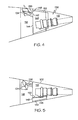
- FIG. 1 is a side view of a schematic of an aircraft tailcone with a portion of its sidewall removed;
- FIG. 2 is a side view of a schematic of another exemplary aircraft inlet assembly with a portion of its sidewall removed;
- FIG. 3 is a top view of the exemplary aircraft inlet assembly shown in FIG. 2;
- FIG. 4 is a side view of a schematic of still another exemplary aircraft inlet assembly with a portion of its sidewall removed;
- FIG. 5 is a top view of the exemplary aircraft inlet assembly shown in FIG. 4;
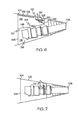
- FIG. 6 is a side view of a schematic of yet another exemplary aircraft inlet assembly with a portion of its sidewall removed;
- FIG. 7 is a top view of the exemplary aircraft inlet assembly shown in FIG. 6;
- FIG. 8 is a side view of a schematic of yet another exemplary aircraft inlet assembly with a portion of its sidewall removed.
- FIG. 9 is a top view of the exemplary aircraft inlet assembly shown in FIG. 8.
- FIG. 1 shows a side view of a simplified aircraft tailcone 100 having an auxiliary power unit (“APU") 136 disposed therein.
- the tailcone 100 includes a tubular sidewall 102, a forward end 104 and an aft end 106.
- the forward end 104 includes an end wall 108 coupled thereto.
- Disposed between the forward end 104 and the aft end 106 are an air inlet opening 112 and a partition 110.
- the air inlet opening 112 is formed in the tailcone sidewall 102 and although shown in FIG.
- the air inlet opening 112 may be formed in any circumferential position around the tubular sidewall 102.
- a ram air door 114 is disposed over the inlet opening 112.
- the partition 110 is disposed inside the tailcone 100 to divide the tailcone 100 into a first and a second compartment 116, 118. Both compartments 116, 118 communicate with the air inlet opening 112 via a first inlet duct 124 and a second inlet duct 126, respectively.
- the first and second inlet ducts 124, 126 have a side-by-side configuration such that the ram air door 114 services both ducts 124, 126..
- the first inlet duct 124 is defined between an inlet 122 and a first outlet 128 and directs air to the first compartment 116.
- the second inlet duct 126 is defined between the inlet 122 and a second outlet 130, and extends through an opening 142 in the partition 110 to provide air to the second compartment 118.
- the first compartment 116 isolates and dampens noise that propagates from the APU 136.
- the noise may be dampened in several ways.
- the first compartment 116 may have one or more sections of acoustically-treated material 132 disposed therein.
- the acoustically-treated material 132 may be any suitable material capable of damping noise, such as, for example, a porous facesheet bonded to a honeycomb material, a porous facesheet having baffles therein, or a bulk material with or without a facesheet. Additionally, the acoustically-treated material 132 may be disposed in any section of the first compartment 116. In one example, as shown in FIG.
- the acoustically-treated material 132 is coupled to the end wall 108 towards the bottom of the tailcone 100 and oriented to reflect noise into the first compartment 116.
- the acoustically-treated material 132 is coupled to a top portion of the tailcone sidewall 102, as shown in FIGs. 6 and 8. In both cases, the acoustically-treated material 132 causes the APU 136 noise to propagate directly therein thereby maximizing attenuation.
- the first inlet duct 124 may be configured to cooperate with the first compartment 116 to further dampen noise.
- the first inlet duct may include a dump diffuser 133.
- the dump diffuser 133 can also minimize aerodynamic losses.
- the dump diffuser 133 has geometric characteristics that provide minimum aerodynamic loss while maintaining a relatively large change in cross-sectional area between the inlet 122 and the first outlet 128. This change in cross-sectional area slows air flow and reduces aerodynamic dump loss into first compartment 116.
- the first inlet duct 124 may be a straight walled diffuser, or a curved wall diffuser. A curved wall diffuser provides maximum flow velocity reduction while having a relatively short length.
- a section of the first inlet duct 124 proximate the first outlet 128 has walls 134 that flare radially outward at a curvature measured from an axis that extends through the center of the duct 124 that is between about 7 degrees and about 24 degrees.
- the second compartment 118 houses the APU 136 and is configured to receive air from the second inlet duct 126 to cool the second compartment 118 and provide air to an oil cooler 137 and eductor system 139 on the APU 136 for cooling oil within the APU 136.
- the exhaust opening 140 is formed in the sidewall 102 proximate the aft end 106 and communicates with the APU 136 to allow byproducts therefrom to exit the tailcone 100.
- the second inlet duct 126 may be defined as a curved wall dump diffuser to minimize inlet pressure losses.
- first compartment 116 and second compartment 118 may have any one of numerous configurations that depend upon the configuration of the partition 110.
- the partition 110 is a single wall 148 that extends radially inward from the tailcone sidewall 102 to substantially seal the first compartment 116 from the second compartment 118.
- the partition 110 includes a first opening 142, as briefly mentioned above, to which the second inlet duct 126 is sealingly coupled.
- the partition 110 may also serve as a firewall to isolate the second compartment 118 from the first compartment 116.
- the partition 110 may also include a second opening 144 coupled to a side channel 146 that directs air from the first compartment 116 to the APU 136.
- the side channel 146 may be positioned along any portion of the aircraft, such as, for example along the side of the second compartment 118 as shown in FIGs. 2 and 3. Positioning the side channel 146 on the side of the aircraft allows maintenance personnel easier access to the APU 136.
- the cross-sectional area of the side channel 146 proximate the second opening 144 is smaller than the cross-sectional area of the side channel 146 in other sections thereof. In this regard, the acoustic benefit of the side channel 146 is maximized without increasing aerodynamic losses and flow-induced noise beyond acceptable levels.
- the side channel 146 may have one or more sections of acoustically treated material 132 disposed therein. It will be appreciated that although FIGs. 2 and 3 show the side channel 146 in a single position, it may be placed along any circumferential location around the APU 136
- the side channel 146 may be enlarged to define a plenum that communicates with the APU' 136.
- the partition 110 comprises a plurality of walls.
- the partition 110 includes a first wall 148 within which the second opening 144 is formed and a second wall 152 that extends from the first wall 148.
- the plenum 146 is shown on the side of the APU 136, it will be appreciated that the second wall 152 may be oriented along any circumferential position around the APU 136.
- the plenum 146 may also include acoustically-treated material 132 to decrease noise that propagates therein.
- the acoustically-treated material 132 may be coupled to the sidewall 102 or any other section of the plenum 146.
- the partition 110 includes the first wall 148 and the second wall 152.
- the first wall 148 is disposed between the APU 136 and the tailcone sidewall 102 and extends aft from the end wall 108.
- the first wall 148 includes opening 144 formed therein that communicates directly with the APU 136 via a duct 150.
- the second wall 152 extends from the first wall 148 to the tailcone sidewall 102 and includes opening 142 through which the second inlet duct 126 communicates with the second compartment 118.
- the air inlet opening 112 is shown disposed substantially in the middle of the tailcone 100, it will be appreciated that the air inlet opening 112 may be formed in any other suitable section of the tailcone 100.
- the air inlet opening 112 may be formed proximate the forward end 104 of the tailcone 100.
- the opening 142 through which the second inlet duct 126 communicates with the second compartment 118 may be formed in the first wall 148.
Landscapes
- Engineering & Computer Science (AREA)
- Chemical & Material Sciences (AREA)
- Combustion & Propulsion (AREA)
- Aviation & Aerospace Engineering (AREA)
- Mechanical Engineering (AREA)
- General Engineering & Computer Science (AREA)
- Current-Collector Devices For Electrically Propelled Vehicles (AREA)
- Soundproofing, Sound Blocking, And Sound Damping (AREA)
Abstract
Description
- This application claims the benefit of U.S. Provisional Application No. 60/647,923, filed January 27, 2005.
- The present invention relates to aircraft and, more particularly, to a system for decreasing noise propagated by an auxiliary power unit of an aircraft.
- Auxiliary power units ("APU") are used in aircraft to provide electrical power and compressed air to various parts therein. When an aircraft is on the ground, its main source of electrical power comes from the APU. In particular, the APU can power the environmental control systems, air drive hydraulic pumps, and the starters for the engines. When an aircraft is in flight, the APU may provide pneumatic and/or electric power to the aircraft.
- Typically, APUs are located in the aft section of the aircraft, at or near the tailcone section and include inlet and exhaust ducting that exit through an opening in the aircraft fuselage to allow sufficient air flow through to the APU. For aircraft on which APUs operate during flight, a ram air door is typically provided to protect the APU from foreign object damage when not in use and/or during ground movement, and to maximize total pressure supplied to the APU when performance at altitude is required.
- However, while the ram air door is open, noise may propagate from the APU outward from the aircraft fuselage. The noise typically travels through the inlet duct and is deflected from the interior of the ram air-door to sections or service locations of the aircraft that are forward the tailcone. Because many aircraft sections are located forward of the APU, such as, for example, passenger doors, passenger and aircraft personnel cabins, refueling points, and baggage doors, audible noise levels heard by those onboard the aircraft or those on the ground while handling baggage or performing aircraft maintenance may be increased.
- Therefore, there is a need for an aircraft assembly that minimizes noise propagation from the APU when a ram air door is open. There is also a need for an aircraft assembly that delivers airflow to the APU with a minimum amount of pressure loss. There is also need for the aircraft assembly to be light weight and inexpensive to manufacture. The present invention addresses one or more of these needs.
- The present invention provides an aircraft inlet assembly for damping noise from an auxiliary power unit ("APU") of an aircraft having a tailcone including a sidewall with a first end and a second end, and an end wall coupled to the sidewall first end. In one embodiment, and by way of example only, the assembly includes a partition disposed within the tailcone and configured to divide the tailcone into a first compartment and a second compartment, the partition including an opening formed therein, an inlet opening formed in the tailcone sidewall in fluid communication with the first compartment, a first inlet duct extending between the inlet opening and the first compartment, an APU disposed within the second compartment, and a second inlet duct extending between the inlet opening and the partition opening to provide communication between the inlet opening and the second compartment.
- In another embodiment, and by way of example only, the assembly includes a partition dividing the tailcone into a first compartment and a second compartment, the partition comprising a first wall and a second wall, the first wall disposed between the APU and the tailcone sidewall and extending from the tailcone forward end aft, and the second wall- extending from the first wall to the tailcone sidewall, an inlet opening formed in the tailcone sidewall in fluid communication with the first compartment, a first inlet duct extending between the inlet opening and the first compartment, and a second inlet duct extending between the inlet opening and the partition opening to provide communication between the inlet opening and the second compartment.
- In still another embodiment, and by way of example only, the assembly includes an inlet opening formed in the tailcone sidewall, a partition disposed in the tailcone and configured to divide the tailcone into a first compartment and a second compartment, the partition having a first opening and a second opening formed therein, a first inlet duct extending between the inlet opening and the first compartment to provide communication therebetween, a second inlet duct extending between the inlet opening and the partition first opening to provide communication between the inlet opening and the second compartment, an APU disposed within the second compartment, and a side plenum defined in part by the tailcone sidewall to provide communication between the partition second opening and the APU.
- Other independent features and advantages of the preferred aircraft inlet assembly will become apparent from the following detailed description, taken in conjunction with the accompanying drawings which illustrate, by way of example, the principles of the invention.
- FIG. 1 is a side view of a schematic of an aircraft tailcone with a portion of its sidewall removed;
- FIG. 2 is a side view of a schematic of another exemplary aircraft inlet assembly with a portion of its sidewall removed;
- FIG. 3 is a top view of the exemplary aircraft inlet assembly shown in FIG. 2;
- FIG. 4 is a side view of a schematic of still another exemplary aircraft inlet assembly with a portion of its sidewall removed;
- FIG. 5 is a top view of the exemplary aircraft inlet assembly shown in FIG. 4;
- FIG. 6 is a side view of a schematic of yet another exemplary aircraft inlet assembly with a portion of its sidewall removed;
- FIG. 7 is a top view of the exemplary aircraft inlet assembly shown in FIG. 6;
- FIG. 8 is a side view of a schematic of yet another exemplary aircraft inlet assembly with a portion of its sidewall removed; and
- FIG. 9 is a top view of the exemplary aircraft inlet assembly shown in FIG. 8.
- The following detailed description of the invention is merely exemplary in nature and is not intended to limit the invention or the application and uses of the invention. Furthermore, there is no intention to be bound by any theory presented in the preceding background of the invention or the following detailed
- Turning now to the description, FIG. 1 shows a side view of a
simplified aircraft tailcone 100 having an auxiliary power unit ("APU") 136 disposed therein. Thetailcone 100 includes atubular sidewall 102, aforward end 104 and anaft end 106. Theforward end 104 includes anend wall 108 coupled thereto. Disposed between theforward end 104 and theaft end 106 are an air inlet opening 112 and apartition 110. Theair inlet opening 112 is formed in thetailcone sidewall 102 and although shown in FIG. 1 as being formed on a top portion of thesidewall 102 proximate theforward end 104, it will be appreciated that the air inlet opening 112 may be formed in any circumferential position around thetubular sidewall 102. To increase total pressure recovery to the APU 136 while in flight, aram air door 114 is disposed over the inlet opening 112. Thepartition 110 is disposed inside thetailcone 100 to divide thetailcone 100 into a first and asecond compartment compartments first inlet duct 124 and asecond inlet duct 126, respectively. Preferably, the first andsecond inlet ducts ram air door 114 services bothducts - The
first inlet duct 124 is defined between aninlet 122 and afirst outlet 128 and directs air to thefirst compartment 116. Thesecond inlet duct 126 is defined between theinlet 122 and asecond outlet 130, and extends through anopening 142 in thepartition 110 to provide air to thesecond compartment 118. - The
first compartment 116 isolates and dampens noise that propagates from the APU 136. The noise may be dampened in several ways. In one exemplary embodiment, thefirst compartment 116 may have one or more sections of acoustically-treatedmaterial 132 disposed therein. The acoustically-treatedmaterial 132 may be any suitable material capable of damping noise, such as, for example, a porous facesheet bonded to a honeycomb material, a porous facesheet having baffles therein, or a bulk material with or without a facesheet. Additionally, the acoustically-treatedmaterial 132 may be disposed in any section of thefirst compartment 116. In one example, as shown in FIG. 1, the acoustically-treatedmaterial 132 is coupled to theend wall 108 towards the bottom of thetailcone 100 and oriented to reflect noise into thefirst compartment 116. In another example, the acoustically-treatedmaterial 132 is coupled to a top portion of thetailcone sidewall 102, as shown in FIGs. 6 and 8. In both cases, the acoustically-treatedmaterial 132 causes theAPU 136 noise to propagate directly therein thereby maximizing attenuation. - Returning to FIG. 1, the
first inlet duct 124 may be configured to cooperate with thefirst compartment 116 to further dampen noise. In this regard, the first inlet duct may include adump diffuser 133. Thedump diffuser 133 can also minimize aerodynamic losses. Preferably, thedump diffuser 133 has geometric characteristics that provide minimum aerodynamic loss while maintaining a relatively large change in cross-sectional area between theinlet 122 and thefirst outlet 128. This change in cross-sectional area slows air flow and reduces aerodynamic dump loss intofirst compartment 116. Thefirst inlet duct 124 may be a straight walled diffuser, or a curved wall diffuser. A curved wall diffuser provides maximum flow velocity reduction while having a relatively short length. In one exemplary embodiment, a section of thefirst inlet duct 124 proximate thefirst outlet 128 haswalls 134 that flare radially outward at a curvature measured from an axis that extends through the center of theduct 124 that is between about 7 degrees and about 24 degrees. - The
second compartment 118 houses the APU 136 and is configured to receive air from thesecond inlet duct 126 to cool thesecond compartment 118 and provide air to anoil cooler 137 andeductor system 139 on theAPU 136 for cooling oil within the APU 136. Theexhaust opening 140 is formed in thesidewall 102 proximate theaft end 106 and communicates with theAPU 136 to allow byproducts therefrom to exit thetailcone 100. Similar to thefirst inlet duct 124, thesecond inlet duct 126 may be defined as a curved wall dump diffuser to minimize inlet pressure losses. - It will be appreciated that the
first compartment 116 andsecond compartment 118 may have any one of numerous configurations that depend upon the configuration of thepartition 110. In one exemplary embodiment, as shown in FIG. 1, thepartition 110 is asingle wall 148 that extends radially inward from thetailcone sidewall 102 to substantially seal thefirst compartment 116 from thesecond compartment 118. Thepartition 110 includes afirst opening 142, as briefly mentioned above, to which thesecond inlet duct 126 is sealingly coupled. Thepartition 110 may also serve as a firewall to isolate thesecond compartment 118 from thefirst compartment 116. - The
partition 110 may also include asecond opening 144 coupled to aside channel 146 that directs air from thefirst compartment 116 to theAPU 136. Theside channel 146 may be positioned along any portion of the aircraft, such as, for example along the side of thesecond compartment 118 as shown in FIGs. 2 and 3. Positioning theside channel 146 on the side of the aircraft allows maintenance personnel easier access to theAPU 136. In a preferred embodiment, the cross-sectional area of theside channel 146 proximate thesecond opening 144 is smaller than the cross-sectional area of theside channel 146 in other sections thereof. In this regard, the acoustic benefit of theside channel 146 is maximized without increasing aerodynamic losses and flow-induced noise beyond acceptable levels. Theside channel 146 may have one or more sections of acoustically treatedmaterial 132 disposed therein. It will be appreciated that although FIGs. 2 and 3 show theside channel 146 in a single position, it may be placed along any circumferential location around theAPU 136 - In another exemplary embodiment, as shown in FIGS. 4 and 5, the
side channel 146 may be enlarged to define a plenum that communicates with the APU' 136. In this case, thepartition 110 comprises a plurality of walls. Specifically, thepartition 110 includes afirst wall 148 within which thesecond opening 144 is formed and asecond wall 152 that extends from thefirst wall 148. While theplenum 146 is shown on the side of theAPU 136, it will be appreciated that thesecond wall 152 may be oriented along any circumferential position around theAPU 136. Theplenum 146 may also include acoustically-treatedmaterial 132 to decrease noise that propagates therein. The acoustically-treatedmaterial 132 may be coupled to thesidewall 102 or any other section of theplenum 146. - Turning now to FIGs. 6 and 7, still another exemplary embodiment is illustrated. In this embodiment, the
partition 110, includes thefirst wall 148 and thesecond wall 152. However, thefirst wall 148 is disposed between theAPU 136 and thetailcone sidewall 102 and extends aft from theend wall 108. Thefirst wall 148 includes opening 144 formed therein that communicates directly with theAPU 136 via aduct 150. Thesecond wall 152 extends from thefirst wall 148 to thetailcone sidewall 102 and includesopening 142 through which thesecond inlet duct 126 communicates with thesecond compartment 118. Although theair inlet opening 112 is shown disposed substantially in the middle of thetailcone 100, it will be appreciated that theair inlet opening 112 may be formed in any other suitable section of thetailcone 100. For example, as shown in FIGs. 8 and 9, theair inlet opening 112 may be formed proximate theforward end 104 of thetailcone 100. In such case, theopening 142 through which thesecond inlet duct 126 communicates with thesecond compartment 118 may be formed in thefirst wall 148. - While the invention has been described with reference to a preferred embodiment, it will be understood by those skilled in the art that various changes may be made and equivalents may be substituted for elements thereof without departing from the scope of the invention. In addition, many modifications may be made to adapt to a particular situation or material to the teachings of the invention without departing from the essential scope thereof. Therefore, it is intended that the invention not be limited to the particular embodiment disclosed as the best mode contemplated for carrying out this invention, but that the invention will include all embodiments falling within the scope of the appended claims.
Claims (10)
- An aircraft inlet assembly for damping noise from an auxiliary power unit ("APU") (136) of an aircraft having a tailcone (100) including a sidewall (102) with a first end (104) and a second end (106), and an end wall (108) coupled to the sidewall first end (104), the assembly comprising:a partition (110) disposed within the tailcone (100) and configured to divide the tailcone (100) into a first compartment (116) and a second compartment (118), the partition (110) including an opening (142) formed therein;an inlet opening (112) formed in the tailcone sidewall (102) in fluid communication with the first compartment (116);a first inlet duct (124) extending between the inlet opening (112) and the first compartment (116);an APU (136) disposed within the second compartment (118); anda second inlet duct (126) extending between the inlet opening (112) and the partition opening (142) to provide communication between the inlet opening (112) and the second compartment (118).
- The assembly of claim 1, wherein the inlet opening (112) is formed along a circumferential portion of the tailcone sidewall (102).
- The assembly of claim 1, wherein the first inlet duct (124) and the second inlet duct (126) have a side-by-side configuration.
- The assembly of claim 1, wherein the partition (110) includes a second opening (144) and the assembly further comprises:a wall (152) extending from the partition (110) to the APU (136); anda side plenum (146) defined between the wall (152) and the tailcone sidewall (102), wherein the side plenum (146) is in communication with the second opening (144).
- The assembly of claim 4, further comprising an acoustically-treated material (132) disposed within the side plenum (146).
- The assembly of claim 1, further comprising an acoustically-treated material (132) disposed within the first compartment (116).
- The assembly of claim 1, wherein the partition (110) includes a second opening (144) and the assembly further comprises a duct (146) extending from the partition second opening (144) to the APU (136).
- The assembly of claim 1, wherein the partition (110) includes a first wall (148) that is disposed between the APU (136) and the tailcone sidewall (102) and extends from the tailcone forward end (104) aft and a second wall (152) extending from the first wall (148) to the tailcone sidewall (102).
- The assembly of claim 8, wherein the partition (110) includes a second opening (144) formed therein, the second opening (144) in communication with the APU (136).
- The assembly of claim 9, further comprising a duct disposed between the partition second opening (144) and the APU (136).
Applications Claiming Priority (2)
| Application Number | Priority Date | Filing Date | Title |
|---|---|---|---|
| US64792305P | 2005-01-27 | 2005-01-27 | |
| US11/159,560 US20060163425A1 (en) | 2005-01-27 | 2005-06-22 | Aircraft inlet assembly for reducing auxiliary power unit noise |
Publications (2)
| Publication Number | Publication Date |
|---|---|
| EP1686058A1 true EP1686058A1 (en) | 2006-08-02 |
| EP1686058B1 EP1686058B1 (en) | 2008-05-21 |
Family
ID=35985187
Family Applications (1)
| Application Number | Title | Priority Date | Filing Date |
|---|---|---|---|
| EP06250422A Expired - Lifetime EP1686058B1 (en) | 2005-01-27 | 2006-01-26 | Aircraft inlet assembly for reducing auxiliary power unit noise |
Country Status (3)
| Country | Link |
|---|---|
| US (1) | US20060163425A1 (en) |
| EP (1) | EP1686058B1 (en) |
| DE (1) | DE602006001213D1 (en) |
Cited By (7)
| Publication number | Priority date | Publication date | Assignee | Title |
|---|---|---|---|---|
| US7344107B2 (en) | 2004-10-26 | 2008-03-18 | The Boeing Company | Dual flow APU inlet and associated systems and methods |
| US7364116B2 (en) | 2004-09-27 | 2008-04-29 | The Boeing Company | Automatic control systems for aircraft auxiliary power units, and associated methods |
| US7765784B2 (en) | 2006-09-25 | 2010-08-03 | The Boeing Company | Thermally compliant APU exhaust duct arrangements and associated systems and methods |
| US8657227B1 (en) | 2009-09-11 | 2014-02-25 | The Boeing Company | Independent power generation in aircraft |
| US8738268B2 (en) | 2011-03-10 | 2014-05-27 | The Boeing Company | Vehicle electrical power management and distribution |
| FR3010971A1 (en) * | 2013-09-25 | 2015-03-27 | Airbus Operations Sas | DEVICE FOR ACOUSTICALLY PROTECTING AN AIR INPUT / OUTPUT OF A PART OF AN AIRCRAFT FUSELAGE |
| EP3034408A1 (en) * | 2014-12-17 | 2016-06-22 | Honeywell International Inc. | Compartment based inlet particle separator system |
Families Citing this family (17)
| Publication number | Priority date | Publication date | Assignee | Title |
|---|---|---|---|---|
| US7210653B2 (en) | 2002-10-22 | 2007-05-01 | The Boeing Company | Electric-based secondary power system architectures for aircraft |
| US7513119B2 (en) | 2005-02-03 | 2009-04-07 | The Boeing Company | Systems and methods for starting aircraft engines |
| CA2581827C (en) * | 2006-03-16 | 2014-05-27 | Hamilton Sundstrand Corporation | Low noise exhaust ducting system |
| US20080236939A1 (en) * | 2007-03-30 | 2008-10-02 | Hamilton Sundstrand Corporation | Exhaust silencer assembly |
| ITTO20080142A1 (en) * | 2008-02-28 | 2009-08-29 | Alenia Aeronautica Spa | AIR INTAKE, IN PARTICULAR FOR A CHAFF EXULSER FOR AIRCRAFT |
| FR2928135B1 (en) * | 2008-02-29 | 2010-09-03 | Airbus France | BACK PLANE PROPULSION SYSTEM WITH SEVERABLE SIDE AIR INTAKE AND PLANE HAVING SUCH A SYSTEM. |
| US8113767B2 (en) * | 2008-09-15 | 2012-02-14 | Hamilton Sundstrand Corporation | Auxiliary power unit inlet duct with acoustic silencing |
| US8596568B2 (en) * | 2011-04-26 | 2013-12-03 | Hamilton Sundstrand Corporation | Exhaust silencer with baffles |
| US9254924B2 (en) * | 2011-08-12 | 2016-02-09 | Hamilton Sundstrand Corporation | Pressure influencing assembly for an aircraft auxiliary system |
| US9051057B2 (en) * | 2011-12-28 | 2015-06-09 | Embraer S.A. | Aircraft air inlet diverter assemblies with improved aerodynamic characteristics |
| US9409653B2 (en) * | 2014-09-17 | 2016-08-09 | The Boeing Company | Auxilliary power and thrust unit drive system |
| US10184372B2 (en) * | 2016-05-23 | 2019-01-22 | Honeywell International Inc. | Exhaust systems and methods for gas turbine engine |
| ES2890374T3 (en) * | 2017-10-30 | 2022-01-18 | Airbus Operations Sl | Aircraft tail cone incorporating an APU with annular air intake |
| WO2019113689A1 (en) | 2017-12-15 | 2019-06-20 | Bombardier Inc. | Noise attenuating device to reduce noise generated by an opening in a skin of an aircraft |
| US10967983B2 (en) * | 2019-06-05 | 2021-04-06 | Pratt & Whitney Canada Corp. | Aircraft power plant |
| US12227296B2 (en) * | 2022-03-30 | 2025-02-18 | Toyota Motor Engineering & Manufacturing North America, Inc. | Cooling system for aircraft components |
| US12012217B2 (en) * | 2022-08-22 | 2024-06-18 | Gulfstream Aerospace Corporation | Auxiliary power unit air inlet door with specified acoustic reflecting and/or diffusing characteristics |
Citations (5)
| Publication number | Priority date | Publication date | Assignee | Title |
|---|---|---|---|---|
| US3698509A (en) * | 1971-06-24 | 1972-10-17 | United Aircraft Corp | Inlet noise silencer for a jet engine |
| EP0743247A2 (en) * | 1995-05-15 | 1996-11-20 | The Boeing Company | Passive cooling device and method for cooling an auxiliary power unit on an airoplane |
| EP0807576A2 (en) * | 1996-05-15 | 1997-11-19 | DaimlerChrysler Aerospace Airbus Gesellschaft mit beschränkter Haftung | Ejection and oil system for an auxiliary power unit of an aircraft |
| EP0968918A2 (en) * | 1998-07-01 | 2000-01-05 | The Boeing Company | Auxiliary power unit passive cooling system |
| WO2003037715A1 (en) * | 2001-10-29 | 2003-05-08 | Pratt & Whitney Canada Corp. | Passive cooling system for auxiliary power unit installation |
Family Cites Families (26)
| Publication number | Priority date | Publication date | Assignee | Title |
|---|---|---|---|---|
| US3027713A (en) * | 1958-01-31 | 1962-04-03 | United Aircraft Corp | Slotted jet engine noise suppressor |
| US3033494A (en) * | 1958-08-01 | 1962-05-08 | United Aircraft Corp | Jet wake noise intensity pattern control means |
| US2988302A (en) * | 1959-01-14 | 1961-06-13 | Gen Sound Control Inc | Silencing means for aircraft |
| US3069848A (en) * | 1959-02-23 | 1962-12-25 | Rolls Royce | Jet lift gas turbine engines having thrust augmenting and silencing means |
| GB1225004A (en) * | 1967-10-18 | 1971-03-17 | Messersschmitt Bolkow Blohm G | Housings for aircraft jet engines |
| GB1212875A (en) * | 1967-12-21 | 1970-11-18 | Rolls Royce | Aircraft |
| DE1800933B1 (en) * | 1968-10-03 | 1970-07-23 | Ver Flugtechnische Werke | Arrangement for sound absorption of the turbine engine system of an aircraft |
| US3736074A (en) * | 1972-04-20 | 1973-05-29 | Worthington Cei | Inlet, filter and noise suppressor enclosure for compressing apparatus |
| US4018046A (en) * | 1975-07-17 | 1977-04-19 | Avco Corporation | Infrared radiation suppressor for gas turbine engine |
| US4411399A (en) * | 1981-09-29 | 1983-10-25 | The Boeing Company | Retractable nozzle fairing system for aeroplane center boost engine |
| US4421455A (en) * | 1981-12-22 | 1983-12-20 | The Garrett Corporation | Duct lining |
| DE3407137A1 (en) * | 1984-02-28 | 1985-08-29 | Messerschmitt-Bölkow-Blohm GmbH, 8012 Ottobrunn | DEVICE FOR IMPROVING THE FLOW RATIO AT THE AIR INLET FOR GAS TURBINE ENGINES BUILT IN PLANES |
| US5140819A (en) * | 1989-09-28 | 1992-08-25 | Sundstrand Corporation | Turbine inlet silencer |
| US5694763A (en) * | 1990-04-11 | 1997-12-09 | United Technologies Corporation | Low observable engine inlet system |
| US5265408A (en) * | 1992-02-13 | 1993-11-30 | Allied-Signal Inc. | Exhaust eductor cooling system |
| US5749542A (en) * | 1996-05-28 | 1998-05-12 | Lockheed Martin Corporation | Transition shoulder system and method for diverting boundary layer air |
| US6134876A (en) * | 1997-11-26 | 2000-10-24 | General Electric Company | Gas turbine engine with exhaust expander and compressor |
| DE19850093C1 (en) * | 1998-10-30 | 2000-05-04 | Daimler Chrysler Aerospace | Air intake |
| US6272838B1 (en) * | 1999-02-25 | 2001-08-14 | Alliedsignal, Inc. | Method and apparatus for controlling the inlet duct leading to an auxiliary power unit |
| US6247668B1 (en) * | 1999-07-15 | 2001-06-19 | The Boeing Company | Auxiliary power and thrust unit |
| US6349899B1 (en) * | 2000-04-04 | 2002-02-26 | The Boeing Company | Aircraft auxiliary air intake with ram and flush opening door |
| US6581874B2 (en) * | 2000-09-27 | 2003-06-24 | Lord Corporation | Mounting assembly for an aircraft auxiliary power unit and method |
| US20020092948A1 (en) * | 2001-01-16 | 2002-07-18 | Dugan John J. | Apparatus and method for reducing jet engine noise |
| US6695094B2 (en) * | 2001-02-02 | 2004-02-24 | The Boeing Company | Acoustic muffler for turbine engine |
| US6615576B2 (en) * | 2001-03-29 | 2003-09-09 | Honeywell International Inc. | Tortuous path quiet exhaust eductor system |
| US7152410B2 (en) * | 2004-06-10 | 2006-12-26 | Honeywell International, Inc. | System and method for dumping surge flow into eductor primary nozzle for free turbine |
-
2005
- 2005-06-22 US US11/159,560 patent/US20060163425A1/en not_active Abandoned
-
2006
- 2006-01-26 EP EP06250422A patent/EP1686058B1/en not_active Expired - Lifetime
- 2006-01-26 DE DE602006001213T patent/DE602006001213D1/en not_active Expired - Fee Related
Patent Citations (5)
| Publication number | Priority date | Publication date | Assignee | Title |
|---|---|---|---|---|
| US3698509A (en) * | 1971-06-24 | 1972-10-17 | United Aircraft Corp | Inlet noise silencer for a jet engine |
| EP0743247A2 (en) * | 1995-05-15 | 1996-11-20 | The Boeing Company | Passive cooling device and method for cooling an auxiliary power unit on an airoplane |
| EP0807576A2 (en) * | 1996-05-15 | 1997-11-19 | DaimlerChrysler Aerospace Airbus Gesellschaft mit beschränkter Haftung | Ejection and oil system for an auxiliary power unit of an aircraft |
| EP0968918A2 (en) * | 1998-07-01 | 2000-01-05 | The Boeing Company | Auxiliary power unit passive cooling system |
| WO2003037715A1 (en) * | 2001-10-29 | 2003-05-08 | Pratt & Whitney Canada Corp. | Passive cooling system for auxiliary power unit installation |
Cited By (13)
| Publication number | Priority date | Publication date | Assignee | Title |
|---|---|---|---|---|
| US7891605B2 (en) | 2004-09-27 | 2011-02-22 | The Boeing Company | Automatic control systems for aircraft auxiliary power units, and associated methods |
| US7364116B2 (en) | 2004-09-27 | 2008-04-29 | The Boeing Company | Automatic control systems for aircraft auxiliary power units, and associated methods |
| US8061650B2 (en) | 2004-09-27 | 2011-11-22 | The Boeing Company | Automatic control systems for aircraft auxiliary power units, and associated methods |
| US7611093B2 (en) | 2004-10-26 | 2009-11-03 | The Boeing Company | Dual flow APU inlet and associated systems and methods |
| US7344107B2 (en) | 2004-10-26 | 2008-03-18 | The Boeing Company | Dual flow APU inlet and associated systems and methods |
| GB2419640B (en) * | 2004-10-26 | 2008-05-21 | Boeing Co | Dual flow apu inlet and associated systems and methods |
| US7765784B2 (en) | 2006-09-25 | 2010-08-03 | The Boeing Company | Thermally compliant APU exhaust duct arrangements and associated systems and methods |
| US8657227B1 (en) | 2009-09-11 | 2014-02-25 | The Boeing Company | Independent power generation in aircraft |
| US8950703B2 (en) | 2009-09-11 | 2015-02-10 | The Boeing Company | Independent power generation in aircraft |
| US8738268B2 (en) | 2011-03-10 | 2014-05-27 | The Boeing Company | Vehicle electrical power management and distribution |
| FR3010971A1 (en) * | 2013-09-25 | 2015-03-27 | Airbus Operations Sas | DEVICE FOR ACOUSTICALLY PROTECTING AN AIR INPUT / OUTPUT OF A PART OF AN AIRCRAFT FUSELAGE |
| EP3034408A1 (en) * | 2014-12-17 | 2016-06-22 | Honeywell International Inc. | Compartment based inlet particle separator system |
| US9719352B2 (en) | 2014-12-17 | 2017-08-01 | Honeywell International Inc. | Compartment based inlet particle separator system |
Also Published As
| Publication number | Publication date |
|---|---|
| DE602006001213D1 (en) | 2008-07-03 |
| US20060163425A1 (en) | 2006-07-27 |
| EP1686058B1 (en) | 2008-05-21 |
Similar Documents
| Publication | Publication Date | Title |
|---|---|---|
| EP1686058B1 (en) | Aircraft inlet assembly for reducing auxiliary power unit noise | |
| US9057329B2 (en) | Turboprop engine systems with noise reducing inlet assemblies | |
| US7267297B2 (en) | Integrated axially varying engine muffler, and associated methods and systems | |
| EP0968918B1 (en) | Auxiliary power unit passive cooling system | |
| US8512450B2 (en) | Engine air particle separator | |
| EP1847458B1 (en) | Diffusing air inlet door assembly | |
| US4240250A (en) | Noise reducing air inlet for gas turbine engines | |
| US6920958B2 (en) | Annular acoustic panel | |
| US6615576B2 (en) | Tortuous path quiet exhaust eductor system | |
| US4749150A (en) | Turbofan duct with noise suppression and boundary layer control | |
| CA2665152C (en) | Sonic absorption device for an air pipeline of an aircraft, in particular of an air conditioning system of an aircraft | |
| US10252811B2 (en) | Acoustic controlled ice deflecting auxiliary power unit inlet system | |
| US8235170B1 (en) | Integrated tailcone muffler assemblies and methods | |
| CN101909998A (en) | Aircraft Cabin Guidance System Device | |
| MX2010014247A (en) | Integrated nacelle assembly. | |
| US3698509A (en) | Inlet noise silencer for a jet engine | |
| CN116806353A (en) | Reduced volume acoustic treatment panel for turbojet engine | |
| US20160368616A1 (en) | Pylon with noise attenuating fairing | |
| US20130000748A1 (en) | Device for ejecting gas from a gas turbine engine and gas turbine engine | |
| US20060032974A1 (en) | Modular installation kit for auxiliary power unit | |
| EA009545B1 (en) | Auxiliary power unit intake duct with aero-acoustic guide vanes | |
| US9194293B2 (en) | Air inlet noise attenuation assembly | |
| EP1748177A1 (en) | Compact, light weight eductor oil cooler plenum and surge flow plenum design | |
| JP2025106209A (en) | Vehicle Fan Mounting Assembly | |
| CA2591357A1 (en) | Compact, light weight eductor oil cooler plenum and surge flow plenum design |
Legal Events
| Date | Code | Title | Description |
|---|---|---|---|
| PUAI | Public reference made under article 153(3) epc to a published international application that has entered the european phase |
Free format text: ORIGINAL CODE: 0009012 |
|
| AK | Designated contracting states |
Kind code of ref document: A1 Designated state(s): AT BE BG CH CY CZ DE DK EE ES FI FR GB GR HU IE IS IT LI LT LU LV MC NL PL PT RO SE SI SK TR |
|
| AX | Request for extension of the european patent |
Extension state: AL BA HR MK YU |
|
| 17P | Request for examination filed |
Effective date: 20070122 |
|
| 17Q | First examination report despatched |
Effective date: 20070222 |
|
| AKX | Designation fees paid |
Designated state(s): DE GB |
|
| GRAP | Despatch of communication of intention to grant a patent |
Free format text: ORIGINAL CODE: EPIDOSNIGR1 |
|
| RIN1 | Information on inventor provided before grant (corrected) |
Inventor name: SHEORAN, YOGENDRA Y.C/O HONEYWELL INTERNATIONAL IN Inventor name: BROWN, DANIEL V.C/O HONEYWELL INTERNATIONAL INC., |
|
| GRAS | Grant fee paid |
Free format text: ORIGINAL CODE: EPIDOSNIGR3 |
|
| GRAA | (expected) grant |
Free format text: ORIGINAL CODE: 0009210 |
|
| AK | Designated contracting states |
Kind code of ref document: B1 Designated state(s): DE GB |
|
| REG | Reference to a national code |
Ref country code: GB Ref legal event code: FG4D |
|
| REF | Corresponds to: |
Ref document number: 602006001213 Country of ref document: DE Date of ref document: 20080703 Kind code of ref document: P |
|
| PLBE | No opposition filed within time limit |
Free format text: ORIGINAL CODE: 0009261 |
|
| STAA | Information on the status of an ep patent application or granted ep patent |
Free format text: STATUS: NO OPPOSITION FILED WITHIN TIME LIMIT |
|
| 26N | No opposition filed |
Effective date: 20090224 |
|
| PG25 | Lapsed in a contracting state [announced via postgrant information from national office to epo] |
Ref country code: DE Free format text: LAPSE BECAUSE OF NON-PAYMENT OF DUE FEES Effective date: 20090801 |
|
| GBPC | Gb: european patent ceased through non-payment of renewal fee |
Effective date: 20100126 |
|
| PG25 | Lapsed in a contracting state [announced via postgrant information from national office to epo] |
Ref country code: GB Free format text: LAPSE BECAUSE OF NON-PAYMENT OF DUE FEES Effective date: 20100126 |
|
| P01 | Opt-out of the competence of the unified patent court (upc) registered |
Effective date: 20230525 |