EP1684637B1 - Collimator and radiation irradiator - Google Patents
Collimator and radiation irradiator Download PDFInfo
- Publication number
- EP1684637B1 EP1684637B1 EP03773441A EP03773441A EP1684637B1 EP 1684637 B1 EP1684637 B1 EP 1684637B1 EP 03773441 A EP03773441 A EP 03773441A EP 03773441 A EP03773441 A EP 03773441A EP 1684637 B1 EP1684637 B1 EP 1684637B1
- Authority
- EP
- European Patent Office
- Prior art keywords
- pair
- radiation
- plate members
- plate
- aperture
- Prior art date
- Legal status (The legal status is an assumption and is not a legal conclusion. Google has not performed a legal analysis and makes no representation as to the accuracy of the status listed.)
- Expired - Lifetime
Links
Images






Classifications
-
- G—PHYSICS
- G21—NUCLEAR PHYSICS; NUCLEAR ENGINEERING
- G21K—HANDLING OF PARTICLES OR IONISING RADIATION NOT OTHERWISE PROVIDED FOR; IRRADIATION DEVICES; GAMMA RAY OR X-RAY MICROSCOPES
- G21K1/00—Arrangements for handling particles or ionising radiation, e.g. focusing or moderating
- G21K1/02—Arrangements for handling particles or ionising radiation, e.g. focusing or moderating using diaphragms, collimators
- G21K1/04—Arrangements for handling particles or ionising radiation, e.g. focusing or moderating using diaphragms, collimators using variable diaphragms, shutters, choppers
-
- A—HUMAN NECESSITIES
- A61—MEDICAL OR VETERINARY SCIENCE; HYGIENE
- A61B—DIAGNOSIS; SURGERY; IDENTIFICATION
- A61B6/00—Apparatus or devices for radiation diagnosis; Apparatus or devices for radiation diagnosis combined with radiation therapy equipment
- A61B6/06—Diaphragms
Definitions
- movable blades are constituted by two sets of plate members so that corresponding ones overlap each other, it is possible to reduce the external form of the collimator without sacrificing the aperture.
- a radiation 3 emitted from the radiation source 1 passes through an aperture of a collimator 5 which embodies the present invention and is applied to an object 7.
- the object 7 is an object for fluoroscopy using the radiation 3 or an object for therapy using the radiation 3.
- the radiation which has passed through the object 7 is received by a suitable light receiving means, e.g., a photosensitive plate.
- the collimator 5 has three pairs of blades 501, 501', 503, 503', and 505, 505'.
- Each blade is constituted by a quadrangular plate member.
- the material of the plate members there is used a material of a high radiation absorbance such as, for example, lead (Pb) or tungsten (W), whereby each blade comes to have a radiation shielding property.
- a material of a high radiation absorbance such as, for example, lead (Pb) or tungsten (W), whereby each blade comes to have a radiation shielding property.
- the three pairs of blades 501, 501', 503, 503', and 505, 505' overlap one another in the thickness direction.
- the blades 501 and 501' are upper blades, the blades 503 and 503' are intermediate blades, and the blades 505 and 505' are lower blades.
- the size of the aperture through which the radiation passes is determined in the x direction by the spacing between opposed end faces of the blades 501 and 501' and in the y direction by the spacing between opposed end faces of the cross beams 507 and 507'.
- FIG. 3 A fully closed state of the aperture is shown in Fig. 3 and a fully open state thereof is shown in Fig. 4 .
- the blades 503 and 503' are kept overlapped with the blades 501, 501' and the blades 505, 505'. Consequently, the passage of any other radiation than the radiation passing through the aperture is blocked.
- the shafts 603 and 603' are threaded throughout the overall lengths thereof.
- the arms 601 and 601' are internally threaded at their portions engaged with the shafts 603 and 603'.
- Gears 605 and 605' are provided coaxially at one ends of the shafts 603 and 603' respectively.
- the gears 605 and 605' are in mesh with each other at a gear ratio of 1:1.
- the maximum degree of opening of the aperture is set equal to that in the prior art shown in Fig. 11 , it is possible to reduce the external form of the collimator to about three fourths. Alternatively, if the external form of the collimator is made about the same as in the prior art, it is possible to enlarge the maximum value of the aperture to approximately 4/3 time.
Landscapes
- Health & Medical Sciences (AREA)
- Life Sciences & Earth Sciences (AREA)
- Engineering & Computer Science (AREA)
- Physics & Mathematics (AREA)
- Medical Informatics (AREA)
- High Energy & Nuclear Physics (AREA)
- Radiology & Medical Imaging (AREA)
- Animal Behavior & Ethology (AREA)
- Optics & Photonics (AREA)
- Pathology (AREA)
- Biophysics (AREA)
- Biomedical Technology (AREA)
- Heart & Thoracic Surgery (AREA)
- Molecular Biology (AREA)
- Surgery (AREA)
- Nuclear Medicine, Radiotherapy & Molecular Imaging (AREA)
- General Health & Medical Sciences (AREA)
- Public Health (AREA)
- Veterinary Medicine (AREA)
- Spectroscopy & Molecular Physics (AREA)
- General Engineering & Computer Science (AREA)
- Apparatus For Radiation Diagnosis (AREA)
- Radiation-Therapy Devices (AREA)
Abstract
Description
- The present invention relates to a collimator and a radiation irradiator. Particularly, the invention is concerned with a collimator for a radiation, e. g. , X-ray, and a radiation irradiator provided with the collimator.
- In a radiation irradiator there is used a collimator for controlling the irradiation range of a radiation. The collimator has an aperture which permits a radiation to pass therethrough, and the radiation cannot pass through other than the aperture. Thus, the irradiation range of the radiation is controlled by the aperture. The degree of opening of the aperture can be changed to adjust the irradiation range of the radiation.
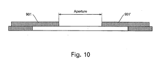
- As shown in
Fig. 10 , the aperture-adjustable collimator has a pair of movable plate members having a radiation shielding property, i.e.,blades 901 and 901'. Theblades 901 and 901' are disposed so that respective end faces are opposed to each other, and are movable in directions opposite to each other in a plane parallel to their surfaces. For widening the aperture, the pair ofblades 901 and 901' are moved away from each other, while for narrowing the aperture, the both blades are moved to close to each other. Thus, the aperture becomes maximum when the pair of blades are remotest from each other, and becomes minimum when both blades are closest to each other. - In a collimator having a large aperture adjusting range, there are used blades of a large area. If the blade area is large, an external form of the collimator comes to have a large size corresponding to a maximum moving distance of blade outer edges, as shown in
Fig. 11 . - In a mammography apparatus which makes fluoroscopy of the breast with X-ray, a collimator assumes a position confronting the face of a subject and so it is preferable that its external form be as small as possible. However, in the case of a mammography apparatus capable of making tomography, an increase in external form of the collimator has heretofore been unavoidable because a large aperture is needed. Document
DE 3236082 describes a device as disclosed in the preamble of claim 1. - Therefore, it is an object of the present invention to provide a collimator capable of being reduced in its external form without sacrificing an aperture, as well as a radiation irradiator provided with such a collimator.
- (1) In one aspect of the present invention for achieving the above-mentioned object there is provided a collimator comprising a pair of first plate members having a shielding property against a radiation and movable in a direction parallel to surfaces thereof, the pair of first plate members defining a radiation passing apertures by a spacing between respective opposed end faces, a pair of second plate members having a shielding property against a radiation and parallel to the pair of first plate members and movable in a direction parallel to surfaces thereof, the pair of second plate members having end faces opposed to each other, the pair of second plate members overlapping the pair of first plate members at least partially so as to block any other radiation than the radiation passing through the aperture, a pair of third plate members having a shielding property against a radiation and parallel to the pair of second plate members, the pair of third plate members having respective end faces opposed to each other with a predetermined spacing, the pair of third plate members overlapping the pair of second plate members at least partially so as to block any other radiation than the radiation passing through the aperture, an adjusting mechanism which adjusts the aperture by moving the pair of first plate members, and a follow-up mechanism which causes the pair of second plate members to move following the pair of first plate members with movement of the first plate members.
- (2) In another aspect of the present invention for achieving the above-mentioned object there is provided a radiation irradiator having a radiation source and a collimator for applying a radiation from the radiation source to an object through an aperture, the collimator comprising a pair of first plate members having a shielding property against a radiation and movable in a direction parallel to surfaces thereof, the pair of first plate members defining a radiation passing aperture by a spacing between respective opposed end faces, a pair of second plate members having a shielding property against a radiation and parallel to the pair of first plate members and movable in a direction parallel to surfaces thereof, the pair of second plate members having end faces opposed to each other, the pair of second plate members overlapping the pair of first plate members at least partially so as to block any other radiation than the radiation passing through the aperture, a pair of third plate members having a shielding property against a radiation and parallel to the pair of second plate members, the pair of third plate members having respective end faces opposed to each other with a predetermined spacing, the pair of third plate members overlapping the pair of second plate members at least partially so as to block any other radiation than the radiation passing through the aperture, an adjusting mechanism which adjusts the aperture by moving the pair of first plate members, and a follow-up mechanism which causes the pair of second plate members to move following the pair of first plate members with movement of the first plate members.
- In the above aspects of the present invention, since movable blades are constituted by two sets of plate members so that corresponding ones overlap each other, it is possible to reduce the external form of the collimator without sacrificing the aperture.
- For changing the aperture symmetrically with respect to the center of the collimator, it is preferable that the adjusting mechanism be able to move the pair of first plate members so as to be closed to and away from each other.
- For permitting an appropriate follow-up motion of the pair of second plate members with respect to the pair of first plate members, it is preferable that the follow-up mechanism comprise a rack provided in the first plate member, a gear provided in the second plate member rotatably and engaging with the rack, and a fixed rack provided in the moving direction of the second plate member and engaging with the gear.
- For the simplification of construction, it is preferable that the follow-up mechanism comprise an arm member mounted at an intermediate portion thereof to the second plate member and rotatable about the mounting portion in a plane parallel to the plate surface, a groove formed in the first plate member and with which one end of the arm member is engaged, the groove permitting movement of the end of the arm member in a direction perpendicular to the moving direction of the first plate member, and a groove formed in the third plate member and with which an opposite end of the arm member is engaged, the groove permitting movement of the opposite end of the arm member in a direction perpendicular to the moving direction of the second plate member.
- For facilitating the adjustment of dose, it is preferable that the radiation be X-ray.
- According to the present invention, it is possible to realize a collimator capable of being reduced in its external size without sacrificing the aperture, as well as a radiation irradiator provided with such a collimator.
- Further objects and advantages of the present invention will be apparent from the following description of the preferred embodiments of the invention as illustrated in the accompanying drawings.
-
-
Fig. 1 illustrates a schematic construction of a radiation irradiator; -
Fig. 2 illustrates the construction of a collimator; -
Fig. 3 illustrates the construction of the collimator; -
Fig. 4 illustrates the construction of the collimator; -
Fig. 5 illustrates a blade drive mechanism; -
Fig. 6 illustrates a partial construction of a blade; -
Fig. 7 illustrates the construction of a follow-up mechanism; -
Fig. 8 illustrates the construction of a follow-up mechanism; -
Fig. 9 illustrates a fully open condition of an aperture; -
Fig. 10 illustrates a conventional collimator; and -
Fig. 11 illustrates a fully open condition of an aperture in the conventional collimator. - Embodiments of the present invention will be described in detail hereinunder with reference to the drawings.
Fig. 1 illustrates a schematic construction of a radiation irradiator according to an embodiment of the present invention. The construction of this radiation irradiator shows an example of how to carry out the present invention. - As shown in the same figure, the radiation irradiator has a radiation source 1. As the radiation source 1 there is used an X-ray tube for example. The radiation source 1 is not limited to the X-ray tube, but may be any other radiation source capable of emitting a suitable radiation such as β ray or γ ray. The radiation source 1 is an example of the radiation source used in the present invention.
- A
radiation 3 emitted from the radiation source 1 passes through an aperture of acollimator 5 which embodies the present invention and is applied to anobject 7. Theobject 7 is an object for fluoroscopy using theradiation 3 or an object for therapy using theradiation 3. In fluoroscopy, the radiation which has passed through theobject 7 is received by a suitable light receiving means, e.g., a photosensitive plate. -
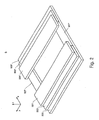
Fig. 2 schematically illustrates thecollimator 5, which embodies the present invention. Through the constitution of this, one embodiment of the present invention is described. - As shown in the same figure, the
collimator 5 has three pairs ofblades - As the material of the plate members there is used a material of a high radiation absorbance such as, for example, lead (Pb) or tungsten (W), whereby each blade comes to have a radiation shielding property.
- The
blades 501 and 501' are an example of the pair of first plate members in the present invention. Theblades 503 and 503' are an example of the pair of second plate members in the present invention. Theblades - In
Fig. 2 , three directions perpendicular to one another assumed to be x, y, and z. The x direction is a direction of one side of each blade, and the direction will hereinafter be referred to also as the width direction. The y direction is a direction of another side of each blade, and the direction will hereinafter be referred to also as the length direction. The z direction is the thickness direction of each blade. The radiation source 1 lies in the z direction. - The three pairs of
blades blades 501 and 501' are upper blades, theblades 503 and 503' are intermediate blades, and theblades - The
lower blades cross beams 507 and 507'. The cross beams 507 and 507' are also constituted by a material of a high radiation absorbance. The cross beams 507 and 507' constitute a picture frame-like frame together with theblades - The
upper blades 501 and 501' are made movable in the x direction by means of a drive mechanism which will be described later. Theblades 501 and 501' are movable so as to be close to and away from each other. - The
intermediate blades 503 and 503' are made movable following theupper blades 501 and 501' by means of a follow-up mechanism to be described later. The movement of theblades 503 and 503' is done while maintaining their overlap with theblades 501, 501' and theblades - The size of the aperture through which the radiation passes is determined in the x direction by the spacing between opposed end faces of the
blades 501 and 501' and in the y direction by the spacing between opposed end faces of the cross beams 507 and 507'. - The aperture size in the x direction varies with movement of the
blades 501 and 501', while the aperture size in the y direction is fixed. That is, thecollimator 5 has an aperture whose size in the x direction can be changed. - A fully closed state of the aperture is shown in
Fig. 3 and a fully open state thereof is shown inFig. 4 . Throughout the whole process of aperture changes, theblades 503 and 503' are kept overlapped with theblades 501, 501' and theblades -
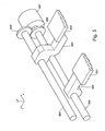
Fig. 5 schematically illustrates the construction of a drive mechanism for theblades 501 and 501'. This drive mechanism is an example of the adjusting mechanism in the present invention. As shown in the same figure, theblades 501 and 501' havearms 601 and 601', respectively, which extend in the y direction. End portions of thearms 601 and 601' are in engagement withshafts - The
shafts blade 501. - The
shafts arms 601 and 601' are internally threaded at their portions engaged with theshafts Gears 605 and 605' are provided coaxially at one ends of theshafts gears 605 and 605' are in mesh with each other at a gear ratio of 1:1. - The
gear 605 is rotated by means of amotor 607. Themotor 607, which is a reversible motor, is controlled by a control means (not shown). The control means controls both rotational direction and rotational quantity of themotor 607. - Since the
gears 605 and 605' are in mesh with each other, theshafts arms 601 and 601' engaged with theshafts motor 607 rotates in one direction, both arms move to be close to each other, while as themotor 607 rotates in the opposite direction, both arms move away from each other. Their movement quantity is determined by the amount of rotation of themotor 607. By such movements of thearms 601 and 601' there is adjusted the spacing between theblades 501 and 501', i.e., the degree of opening of the aperture. In this way the degree of opening of the aperture can be changed symmetrically with respect to the center of the collimator. - There is provided a follow-up mechanism for allowing the
blade 503 and 503' to follow such movements of theblades 501 and 501'. The follow-up mechanism is constituted so as to span the three pairs of blades and the cross beams. As a part of the follow-up mechanism, theblade 503 is constituted as shown inFig. 6 , in which (a) is a plan view and (b) is a sectional view taken on line A-A in (a). - As shown in the same figure, the
blade 503 has agear 701. Thegear 701 is mounted rotatably on ashaft 703 which is provided in theblade 503. To be more specific, theshaft 703 is disposed within acutout portion 705 formed in one end portion in the y direction of theblade 503. Thecutout portion 705 is formed in the x direction and theshaft 703 is mounted so as to cross thecutout portion 705 in the y direction. Thecutout portion 705 is formed on one side in the x direction of theblade 503. The side where thecutout portion 705 is formed confronts the blade 503' which makes a pair with theblade 503. - The
blade 503 has a similar gear also at its opposite end portion in the y direction. That is, theblade 503 has gears at both ends thereof in the y direction. The blade 503' is also of the same construction, provided theblades 503 and 503' are in a relation of specular symmetry. -
Fig. 7 illustrates the construction of the follow-up mechanism schematically. This follow-up mechanism is an example of the follow-up mechanism defined in the present invention. As shown in the same figure, the follow-up mechanism is composed of thegear 701 provided in theblade 503, arack 707 provided in theblade 501 and meshing with thegear 701, and arack 709 provided in bothblade 505 andcross beam 507 and meshing with thegear 701. Theracks - The
gear 701 is an example of the gear defined in the present invention. Therack 707 is an example of the rack defined in the present invention. Therack 709 is an example of the fixed rack defined in the present invention. - As the
blade 501 is moved in the x direction, the gear meshing with therack 707 moves in the same direction while rotating on therack 709. Theblade 503 also moves together with thegear 701. As a result, theblade 503 moves following theblade 501. The distance of the movement of theblade 503 is a half of that of theblade 501. - Such a follow-up mechanism is provided at both end portions of the
blades mating blades 501', 503', and 505'. With the follow-up mechanism, the follow-up motion of theblades 503 and 503' for theblades 501 and 501' can be done appropriately. Consequently, it becomes possible to make such aperture adjustment as shown inFigs. 2 to 4 . -
Fig. 8 schematically shows another constructional example of a follow-up mechanism. This follow-up mechanism is an example of the follow-up mechanism defined in the present invention. In the same figure, (a) is a plan view and (b) is a sectional view taken on line B-B in (a). As shown in the same figure, theblade 503 is provided with ashaft 803 at its center. Theshaft 803 extends through theblade 503 perpendicularly to the plate surface. Theshaft 803 is rotatable. -
Arms shaft 803. Thearms shaft 803 and extend in directions opposite to each other. Theshaft 803 and thearms arms arms - The
arms lugs lugs lug 811 is loosely fitted in agroove 511 formed in theblade 501. Thegroove 511 is positioned on theblade 503 side of theblade 501 and extends in the y direction. Thelug 851 is loosely fitted in agroove 551 formed in theblade 505. Thegroove 551 is positioned on theblade 503 side of theblade 505 and extends in the y direction. Thegrooves - In this construction, when the
blade 501 is moved in the x direction, thelugs grooves shaft 803. - The position of the
blade 505 is fixed, so with the rotation of the crank, theshaft 803 moves in the x direction following theblade 501 and theblade 503 moves in the same direction together with theshaft 803. By setting the lengths of thearms blade 503 becomes half of that of theblade 501. Thus, this follow-up mechanism becomes simple in construction. - Such a follow-up mechanism is provided also on the side of the
mating blades 501', 503', and 505'. As a result, it becomes possible to make such aperture adjustment as shown inFigs. 2 to 4 . - In the fully open condition of the aperture shown in
Fig. 4 , corresponding ones in the three pairs ofblades Fig. 9 shows this state in terms of a sectional view. As shown in the same figure, themovable blades blades - Therefore, if the maximum degree of opening of the aperture is set equal to that in the prior art shown in
Fig. 11 , it is possible to reduce the external form of the collimator to about three fourths. Alternatively, if the external form of the collimator is made about the same as in the prior art, it is possible to enlarge the maximum value of the aperture to approximately 4/3 time. - Many widely different embodiments of the invention may be configured without departing from the scope of the present invention. It should be understood that the present invention is not limited to the specific embodiments described in the specification, except as defined in the appended claims.
Claims (10)
- A collimator (5) comprising:a pair of first plate members (501,501') having a shielding property against a radiation and movable in a direction parallel to surfaces thereof, the pair of first plate members defining a radiation passing aperture by a spacing between respective opposed end faces;a pair of second plate members (503,503') having a shielding property against a radiation and parallel to the pair of first plate members and movable in a direction parallel to surfaces thereof, the pair of second plate members having end faces opposed to each other in the shielding property, the pair of second plate members overlapping the pair of first plate members at least partially so as to block any other radiation than the radiation passing through the aperture;an adjusting mechanism (601,601',603,603',605,605',607) which adjusts the aperture by moving the pair of first plate members; anda follow-up mechanism (701,703,705,707,709,801,803,805,811,851) which causes the pair of second plate members to move following the pair of first plate members with movement of the first plate members, characterized in that there is a pair of third plate members (505,505') having a shielding property against a radiation and parallel to the pair of second plate members, the pair of third plate members having respective end faces opposed to each other with a predetermined spacing, the pair of third plate members overlapping the pair of second plate members at least partially so as to block any other radiation than the radiation passing through the aperture.
- A collimator according to claim 1, wherein the adjusting mechanism can move the pair of first plate members so as to be close to and away from each other.
- A collimator according to claim 2, wherein the follow-up mechanism comprises:a rack (707) provided in the first plate member;a gear (701) provided in the second plate member rotatably and engaging with the rack; anda fixed rack (709) provided in the moving direction of the second plate member and engaging with the gear.
- A collimator according to claim 1, wherein the follow-up mechanism comprises:an arm member (801,805) mounted at an intermediate portion thereof to the second plate member and rotatable about the mounting portion in a plane parallel to the plate surface;a groove (511) formed in the first plate member and with which one end of the arm member is engaged, the groove permitting movement of the one end of the arm member in a direction perpendicular to the moving direction of the first plate member; anda groove (551) formed in the third plate member and with which an opposite end of the arm member is engaged, the groove permitting movement of the opposite end of the arm member in a direction perpendicular to the moving direction of the second plate member.
- A collimator according to claim 1, wherein the radiation is X-ray.
- A radiation irradiator having a radiation source (1) and a collimator (5) according to claim 1, the radiation irradiator adapted for applying a radiation from the radiation source to an object (7) through an aperture.
- A radiation irradiator according to claim 6, wherein the adjusting mechanism can move the pair of first plate members so as to be close to and away from each other.
- A radiation irradiator according to claim 6, wherein the follow-up mechanism comprises:a rack provided in the first plate member;a gear provided in the second plate member rotatably and engaging with the rack;
anda fixed rack provided in the moving direction of the second plate member and engaging with the gear. - A radiation irradiator according to claim 6, wherein the follow-up mechanism comprises:an arm member mounted at an intermediate portion thereof to the second plate member and rotatable about the mounting portion in a plane parallel to the plate surface;a groove formed in the first plate member and with which one end of the arm member is engaged, the groove permitting movement of the one end of the arm member in a direction perpendicular to the moving direction of the first plate member; anda groove formed in the third plate member and with which an opposite end of the arm member is engaged, the groove permitting movement of the opposite end of the arm member in a direction perpendicular to the moving direction of the second plate member.
- A radiation irradiator according to claim 6, wherein the radiation is X-ray.
Applications Claiming Priority (1)
| Application Number | Priority Date | Filing Date | Title |
|---|---|---|---|
| PCT/CN2003/000985 WO2005048845A1 (en) | 2003-11-20 | 2003-11-20 | Collimator and radiation irradiator |
Publications (3)
| Publication Number | Publication Date |
|---|---|
| EP1684637A1 EP1684637A1 (en) | 2006-08-02 |
| EP1684637A4 EP1684637A4 (en) | 2007-04-18 |
| EP1684637B1 true EP1684637B1 (en) | 2011-02-09 |
Family
ID=34596926
Family Applications (1)
| Application Number | Title | Priority Date | Filing Date |
|---|---|---|---|
| EP03773441A Expired - Lifetime EP1684637B1 (en) | 2003-11-20 | 2003-11-20 | Collimator and radiation irradiator |
Country Status (6)
| Country | Link |
|---|---|
| US (1) | US7397903B2 (en) |
| EP (1) | EP1684637B1 (en) |
| CN (1) | CN100479758C (en) |
| AU (1) | AU2003281907A1 (en) |
| DE (1) | DE60336025D1 (en) |
| WO (1) | WO2005048845A1 (en) |
Cited By (1)
| Publication number | Priority date | Publication date | Assignee | Title |
|---|---|---|---|---|
| JP2010533507A (en) * | 2007-03-19 | 2010-10-28 | プランメカ オイ | Limitation of X-ray beams related to dental imaging |
Families Citing this family (15)
| Publication number | Priority date | Publication date | Assignee | Title |
|---|---|---|---|---|
| US8093572B2 (en) * | 2007-06-29 | 2012-01-10 | Accuray Incorporated | Integrated variable-aperture collimator and fixed-aperture collimator |
| DE102009016770A1 (en) * | 2009-04-07 | 2010-10-21 | Siemens Aktiengesellschaft | Method and device for generating projections from the interior of an examination object |
| ITRM20090666A1 (en) * | 2009-12-18 | 2011-06-19 | Consiglio Naz Delle Ricerche C N R | HIGH SPATIAL RESOLUTION PRINTING DEVICE |
| CN102610291B (en) * | 2011-01-21 | 2016-02-03 | 深圳迈瑞生物医疗电子股份有限公司 | X-ray beam filtration unit, beam-defining clipper and medical diagnosis X radial equipment |
| US9312038B2 (en) * | 2011-05-31 | 2016-04-12 | Hitachi Medical Corporation | X-ray diaphragm mechanism and X-ray CT apparatus |
| EP2925230B1 (en) * | 2012-12-03 | 2020-05-20 | Koninklijke Philips N.V. | Translating x-ray beam transmission profile shaper |
| CN103337272B (en) * | 2013-06-27 | 2016-02-03 | 东软飞利浦医疗设备系统有限责任公司 | X-ray collimator and collimation thereof crack width adjustment method |
| JP6462273B2 (en) * | 2014-08-21 | 2019-01-30 | キヤノンメディカルシステムズ株式会社 | X-ray diagnostic apparatus and X-ray diaphragm |
| CN105769227A (en) * | 2014-12-24 | 2016-07-20 | 丹东市科大仪器有限公司 | Mechanical device for driving multiple layers of protective blades of medical X-ray beam limiting device |
| CN106935293B (en) * | 2015-12-30 | 2019-10-15 | 韩电原子力燃料株式会社 | Nuclear fuel rod density measuring equipment |
| CN105632577B (en) * | 2015-12-31 | 2018-02-16 | 重庆真测科技股份有限公司 | A kind of adjusting means and adjusting method of collimater tomography thickness |
| ITUA20162102A1 (en) * | 2016-03-30 | 2017-09-30 | Cefla S C | BEAM RESTRICTION DEVICE FOR RADIOGRAPHIC EQUIPMENT |
| KR101772324B1 (en) * | 2016-04-18 | 2017-08-28 | 고려대학교 산학협력단 | Variable pin-hole collimator and radiation imaging device using the same |
| CN105931694B (en) * | 2016-05-06 | 2018-05-22 | 东莞中子科学中心 | High-performance neutron collimator and assembling method thereof |
| US12564734B2 (en) * | 2020-10-16 | 2026-03-03 | The Johns Hopkins University | Ultra-high dose rate x-ray cabinet irradiator |
Family Cites Families (23)
| Publication number | Priority date | Publication date | Assignee | Title |
|---|---|---|---|---|
| GB869701A (en) * | 1957-11-26 | 1961-06-07 | Picker X Ray Corp Waite Mfg | Improvements relating to x-ray apparatus |
| DE1092160B (en) * | 1959-04-30 | 1960-11-03 | Siemens Reiniger Werke Ag | Device for parallel adjustment of moving parts of X-ray devices |
| NL7803370A (en) | 1977-04-06 | 1978-10-10 | Kernforschungsanlage Juelich | MULTI-CHANNEL COLLIMATOR DEVICE. |
| US4277685A (en) | 1978-06-12 | 1981-07-07 | Ohio-Nuclear, Inc. | Adjustable collimator |
| US4419585A (en) * | 1981-02-26 | 1983-12-06 | Massachusetts General Hospital | Variable angle slant hole collimator |
| DE3236082A1 (en) * | 1982-09-29 | 1984-03-29 | Siemens AG, 1000 Berlin und 8000 München | Radiation diaphragm for an X-ray examination apparatus |
| FR2650397B1 (en) * | 1989-07-28 | 1991-10-04 | Informatek Ste Nle | SCINTILLATION DEVICE FOR USE IN MEASURING ATTENUATION BY TRANSMISSION TOMOGRAPHY |
| US5166531A (en) * | 1991-08-05 | 1992-11-24 | Varian Associates, Inc. | Leaf-end configuration for multileaf collimator |
| US5438454A (en) | 1993-11-01 | 1995-08-01 | Regents, University Of California | Method for selecting minimum width of leaf in multileaf adjustable collimator while inhibiting passage of particle beams of radiation through sawtooth joints between collimator leaves |
| US5748703A (en) * | 1994-03-22 | 1998-05-05 | Cosman; Eric R. | Dynamic collimator for a linear accelerator |
| US5436958A (en) | 1994-08-03 | 1995-07-25 | General Electric Company | Adjustable collimator |
| US6052430A (en) * | 1997-09-25 | 2000-04-18 | Siemens Medical Systems, Inc. | Dynamic sub-space intensity modulation |
| US6167114A (en) * | 1998-08-10 | 2000-12-26 | Siemens Medical Systems, Inc. | System and method for calculating scatter radiation including a collimator thickness |
| WO2000060610A1 (en) * | 1999-04-01 | 2000-10-12 | Mamea Imaging Ab | Method and apparatus for simplified alignment in x-ray imaging |
| AU2001229017A1 (en) * | 2000-01-24 | 2001-07-31 | Mamea Imaging Ab | Method and arrangement for variable exposure of x-ray detector |
| US6449340B1 (en) | 2000-07-31 | 2002-09-10 | Analogic Corporation | Adjustable x-ray collimator |
| US6330300B1 (en) | 2000-08-23 | 2001-12-11 | Siemens Medical Solutions Usa, Inc. | High definition intensity modulating radiation therapy system and method |
| FR2818428A1 (en) * | 2000-12-19 | 2002-06-21 | Ge Med Sys Global Tech Co Llc | Adjustable collimator for medical X-ray use has four shutters that can be moved independently, using stepper motors, to create a rectangular aperture of any size |
| US6807250B2 (en) * | 2001-04-30 | 2004-10-19 | Eastman Kodak Company | Collimation device and method for acquiring a radiation image of a long body part using direct digital X-ray detectors |
| FI110478B (en) * | 2001-05-29 | 2003-02-14 | Planmeca Oy | Method and apparatus for delimiting a radiation beam |
| CN2514851Y (en) * | 2001-10-19 | 2002-10-09 | 深圳市一体智能技术有限公司 | Composite moving multivane collimator |
| GB2403884B (en) * | 2003-07-08 | 2006-03-01 | Elekta Ab | Multi-leaf collimator |
| US7133491B2 (en) * | 2004-01-15 | 2006-11-07 | Bio-Imaging Research, Inc. | Traveling X-ray inspection system with collimators |
-
2003
- 2003-11-20 US US10/579,900 patent/US7397903B2/en not_active Expired - Lifetime
- 2003-11-20 DE DE60336025T patent/DE60336025D1/en not_active Expired - Lifetime
- 2003-11-20 CN CNB2003801107294A patent/CN100479758C/en not_active Expired - Fee Related
- 2003-11-20 WO PCT/CN2003/000985 patent/WO2005048845A1/en not_active Ceased
- 2003-11-20 AU AU2003281907A patent/AU2003281907A1/en not_active Abandoned
- 2003-11-20 EP EP03773441A patent/EP1684637B1/en not_active Expired - Lifetime
Cited By (1)
| Publication number | Priority date | Publication date | Assignee | Title |
|---|---|---|---|---|
| JP2010533507A (en) * | 2007-03-19 | 2010-10-28 | プランメカ オイ | Limitation of X-ray beams related to dental imaging |
Also Published As
| Publication number | Publication date |
|---|---|
| CN1878503A (en) | 2006-12-13 |
| EP1684637A4 (en) | 2007-04-18 |
| CN100479758C (en) | 2009-04-22 |
| WO2005048845A1 (en) | 2005-06-02 |
| US20070086576A1 (en) | 2007-04-19 |
| AU2003281907A1 (en) | 2005-06-08 |
| EP1684637A1 (en) | 2006-08-02 |
| DE60336025D1 (en) | 2011-03-24 |
| US7397903B2 (en) | 2008-07-08 |
Similar Documents
| Publication | Publication Date | Title |
|---|---|---|
| US7397903B2 (en) | Collimator and radiation irradiator | |
| KR100943297B1 (en) | Collimator for defining a beam of high-energy rays | |
| US8824638B2 (en) | Systems and methods for making and using multi-blade collimators | |
| US5991362A (en) | Adjustable opening X-ray mask | |
| US7023962B2 (en) | Collimator, X-ray irradiator, and X-ray apparatus | |
| EP2849649B1 (en) | X-ray detector with manipulation unit for movement of detector modules on a circle | |
| US8085903B2 (en) | Shutter mechanism for collimating X-rays | |
| DE4207006A1 (en) | COMPUTER TOMOGRAPH | |
| US7310410B2 (en) | Single-leaf X-ray collimator | |
| US4086494A (en) | Radiation collimator for use with high energy radiation beams | |
| US20100246775A1 (en) | Filter and x-ray imaging apparatus using the filter | |
| CN1142178A (en) | X-ray inspection device with beam stop | |
| EP1102103B1 (en) | Optical device, especially objective, with at least one diaphragm | |
| US3609370A (en) | Radiation collimator for use in x-ray systems | |
| DE69931330T2 (en) | Device for irradiating obliquely incident light | |
| EP1686897B1 (en) | Collimator, x-ray irradiator, and x-ray apparatus | |
| DE10016925A1 (en) | Iris diaphragm | |
| CN100538496C (en) | Light beam diaphragm and X-ray imaging device | |
| US4389730A (en) | Compact collimator | |
| JP3471477B2 (en) | Variable slit device for X-ray equipment | |
| DE102009047672B4 (en) | X-ray optical construction with two focusing elements | |
| US11862357B2 (en) | Adjustable collimators and x-ray imaging systems including adjustable collimators | |
| DE102023107941B3 (en) | Electromechanical shutter device for a thermal imaging camera with a swing arm as shutter blade | |
| KR100872142B1 (en) | Variable collimator | |
| KR20080071727A (en) | Collimator aperture control |
Legal Events
| Date | Code | Title | Description |
|---|---|---|---|
| PUAI | Public reference made under article 153(3) epc to a published international application that has entered the european phase |
Free format text: ORIGINAL CODE: 0009012 |
|
| 17P | Request for examination filed |
Effective date: 20060411 |
|
| AK | Designated contracting states |
Kind code of ref document: A1 Designated state(s): DE FI |
|
| DAX | Request for extension of the european patent (deleted) | ||
| RBV | Designated contracting states (corrected) |
Designated state(s): DE FI |
|
| A4 | Supplementary search report drawn up and despatched |
Effective date: 20070319 |
|
| RIC1 | Information provided on ipc code assigned before grant |
Ipc: G21K 1/04 20060101ALI20070313BHEP Ipc: A61B 6/06 20060101AFI20050609BHEP |
|
| 17Q | First examination report despatched |
Effective date: 20091001 |
|
| GRAP | Despatch of communication of intention to grant a patent |
Free format text: ORIGINAL CODE: EPIDOSNIGR1 |
|
| RIN1 | Information on inventor provided before grant (corrected) |
Inventor name: YANG, ZHAONO. 2 NORTH YONG CHANG ROAD |
|
| GRAS | Grant fee paid |
Free format text: ORIGINAL CODE: EPIDOSNIGR3 |
|
| GRAA | (expected) grant |
Free format text: ORIGINAL CODE: 0009210 |
|
| AK | Designated contracting states |
Kind code of ref document: B1 Designated state(s): DE FI |
|
| REF | Corresponds to: |
Ref document number: 60336025 Country of ref document: DE Date of ref document: 20110324 Kind code of ref document: P |
|
| REG | Reference to a national code |
Ref country code: DE Ref legal event code: R096 Ref document number: 60336025 Country of ref document: DE Effective date: 20110324 |
|
| PLBE | No opposition filed within time limit |
Free format text: ORIGINAL CODE: 0009261 |
|
| STAA | Information on the status of an ep patent application or granted ep patent |
Free format text: STATUS: NO OPPOSITION FILED WITHIN TIME LIMIT |
|
| 26N | No opposition filed |
Effective date: 20111110 |
|
| REG | Reference to a national code |
Ref country code: DE Ref legal event code: R097 Ref document number: 60336025 Country of ref document: DE Effective date: 20111110 |
|
| PGFP | Annual fee paid to national office [announced via postgrant information from national office to epo] |
Ref country code: DE Payment date: 20131113 Year of fee payment: 11 |
|
| PGFP | Annual fee paid to national office [announced via postgrant information from national office to epo] |
Ref country code: FI Payment date: 20131112 Year of fee payment: 11 |
|
| REG | Reference to a national code |
Ref country code: DE Ref legal event code: R119 Ref document number: 60336025 Country of ref document: DE |
|
| PG25 | Lapsed in a contracting state [announced via postgrant information from national office to epo] |
Ref country code: FI Free format text: LAPSE BECAUSE OF NON-PAYMENT OF DUE FEES Effective date: 20141120 |
|
| PG25 | Lapsed in a contracting state [announced via postgrant information from national office to epo] |
Ref country code: DE Free format text: LAPSE BECAUSE OF NON-PAYMENT OF DUE FEES Effective date: 20150602 |