EP1684411A2 - Motor Control - Google Patents
Motor Control Download PDFInfo
- Publication number
- EP1684411A2 EP1684411A2 EP05111269A EP05111269A EP1684411A2 EP 1684411 A2 EP1684411 A2 EP 1684411A2 EP 05111269 A EP05111269 A EP 05111269A EP 05111269 A EP05111269 A EP 05111269A EP 1684411 A2 EP1684411 A2 EP 1684411A2
- Authority
- EP
- European Patent Office
- Prior art keywords
- speed
- velocity
- weighting
- command velocity
- sensed
- Prior art date
- Legal status (The legal status is an assumption and is not a legal conclusion. Google has not performed a legal analysis and makes no representation as to the accuracy of the status listed.)
- Granted
Links
Images


Classifications
-
- H—ELECTRICITY
- H02—GENERATION; CONVERSION OR DISTRIBUTION OF ELECTRIC POWER
- H02P—CONTROL OR REGULATION OF ELECTRIC MOTORS, ELECTRIC GENERATORS OR DYNAMO-ELECTRIC CONVERTERS; CONTROLLING TRANSFORMERS, REACTORS OR CHOKE COILS
- H02P23/00—Arrangements or methods for the control of AC motors characterised by a control method other than vector control
- H02P23/14—Estimation or adaptation of motor parameters, e.g. rotor time constant, flux, speed, current or voltage
-
- H—ELECTRICITY
- H02—GENERATION; CONVERSION OR DISTRIBUTION OF ELECTRIC POWER
- H02P—CONTROL OR REGULATION OF ELECTRIC MOTORS, ELECTRIC GENERATORS OR DYNAMO-ELECTRIC CONVERTERS; CONTROLLING TRANSFORMERS, REACTORS OR CHOKE COILS
- H02P6/00—Arrangements for controlling synchronous motors or other dynamo-electric motors using electronic commutation dependent on the rotor position; Electronic commutators therefor
- H02P6/14—Electronic commutators
- H02P6/16—Circuit arrangements for detecting position
- H02P6/18—Circuit arrangements for detecting position without separate position detecting elements
Definitions
- the present invention relates to motor control.
- a vector control method for accurately calculating the rotational velocity of a motor is used in industry fields that require high performance of the motor.
- a position sensor having a high resolution such as an optical encoder and a resolver, is used because the vector control method requires that the position of the rotor is continuously sensed.
- high resolution position sensors are expensive, and restrict the installation environment of the apparatus for controlling the motor.
- a sensorless vector control method by which the position of the rotor is estimated without the sensor has been proposed for solving the shortcomings of using the position sensor.
- an excitation phase which obtains the maximum torque is determined in accordance with the position of the rotor. Also, the position of the rotor is measured using an inverse electromotive force generated while the rotor rotates. On the basis of the above, the excitation phase which obtains the maximum torque is excited so that the rotation of the motor is controlled.
- the sensorless control method and the apparatus disclosed in US-A-6 081 093 modifies a command velocity and an estimation velocity with a weighting using a membership function, and sums up the command velocity and the weighted estimation velocity allowing smooth movement from a low speed to a high speed. That is, the relative importance of the weight of the command velocity is larger in the initial starting period or during a low-speed period.
- the present invention aims to address the above drawbacks.
- a speed controller for a motor having a rotor, the speed controller operable to control the speed of the rotor in accordance with an estimated reference speed of the rotor, the controller comprising a speed sensing means which senses the rotational position of the rotor, and calculates the sensed speed in accordance with the sensed rotational position of the rotor; a speed estimator which estimates the speed of the rotor in accordance with the position error of the rotor; and a reference speed calculator for determining the estimated reference speed of the rotor in accordance with the sensed speed, the estimated speed or a command velocity, wherein at least one of the sensed speed, the estimated speed, or the command velocity has a weighting applied thereto, the weighting being determined in accordance with the command velocity.
- the reference velocity calculator may be operable to generate the estimated reference speed of the rotor in accordance with the sum of the weighted sensed speed, the weighted estimated speed and the weighted command velocity
- the reference velocity calculator may be operable to divide the total speed range of the rotor into a plurality of speed segments based on the command velocity.
- the plurality of speed segments may comprise a low-speed segment in which the weighting for the command velocity is "1", and the weighting for the sensed speed and the weighting for the estimated speed are "0", a middle-speed segment in which the weighting for the sensed speed is "1", and the weighting for the command velocity and the weighting for the estimated speed are "0", a high-speed segment in which the weighting for the estimated speed is "1", and the weighting for the command velocity and the weighting for the sensed speed are "0”, a first conversion segment between the low-speed segment and the middle-speed segment, and a second conversion segment between the middle-speed segment and the high-speed segment.
- the reference velocity calculator may calculate the sum of the command velocity and the sensed speed, and outputs the sum of the command velocity and the sensed speed as the estimated reference speed in the first conversion segment.
- the reference velocity calculator may decrease the weighting for the command velocity in accordance with an increase of the command velocity, and increases the weighting for the sensed speed in accordance with the increase of the command velocity.
- the reference velocity calculator may calculate the sum of the sensed speed and the estimated speed, and outputs the sum of the sensed speed and the estimated speed as the estimated reference speed in the second conversion period.
- the reference velocity calculator may decrease the weighting for the sensed speed in accordance with an increase of the command velocity, and increases the weighting for the estimated speed in accordance with the increase of the command velocity.
- the reference velocity calculator may linearly decrease the weighting for the command velocity and linearly increases the weighting for the sensed speed in accordance with the increase of the command velocity in the first conversion segment.
- the reference velocity calculator may sigmoidally decrease the weighting for the command velocity and sigmoidally increases the weighting for the sensed speed in accordance with the increase of the command velocity in the first conversion segment.
- the reference velocity calculator may linearly decrease the weighting for the sensed speed and linearly increases the weighting for the estimated speed in accordance with the increase of the command velocity in the second conversion segment.
- the reference velocity calculator may sigmoidally decrease the weighting for the sensed speed and sigmoidally increases the weighting for the estimated speed in accordance with the increase of the command velocity in the second conversion segment.
- a method of controlling the speed of a motor having a rotor wherein the speed of the rotor is controlled in accordance with a reference estimated speed of the rotor
- the method comprising: sensing the rotational position of the rotor, and calculating a sensed speed in accordance with the sensed rotational position of the rotor; providing an estimated speed for the rotor in accordance with the position error of the rotor; and determining the reference estimated speed of the rotor in accordance with the sensed speed, the estimated speed or a command velocity, wherein at least one of the sensed speed, the estimated speed, and the command velocity has a weighting applied thereto.
- an apparatus for controlling a velocity of a motor having a rotor comprising: a sensing velocity calculator which senses a rotation position of the motor, and calculates a sensing velocity on the basis of the sensed rotation position of the motor; a velocity estimator which estimates an estimation velocity of the motor based on information about a position error of the rotor; and a reference velocity calculator which divides an overall velocity period of the motor into a plurality of unit velocity periods based on a command velocity for controlling a rotation velocity of the motor, calculates a sum of the sensing velocity, the estimation velocity, and the command velocity after multiplying at least one of the sensing velocity, the estimation velocity, and the command velocity by a predetermined weight, and outputs the sum as a reference estimation velocity of the motor.
- the plurality of unit velocity periods comprise: a low-speed period in which a weight for the command velocity is "1", and a weight for the sensing velocity and a weight for the estimation velocity are "0"; a middle-speed period in which the weight for the sensing velocity is "1", and the weight for the command velocity and the weight for the estimation velocity are "0”; a high-speed period in which the weight for the estimation velocity is "1", and the weight for the command velocity and the weight for the sensing velocity are "0”; a first conversion period between the low-speed velocity and the middle-speed velocity; and a second conversion period between the middle-speed velocity and the high-speed velocity.
- the reference velocity calculator calculates a sum of the command velocity and the sensing velocity, and outputs the sum of the command velocity and the sensing velocity as the reference estimation velocity in the first conversion period.
- the reference velocity estimator when the command velocity is in the first conversion period, decreases the weight for the command velocity in accordance with an increase of the command velocity, and increases the weight for the sensing velocity in accordance with the increase of the command velocity.
- the reference velocity calculator calculates a sum of the sensing velocity and the estimation velocity, and outputs the sum of the sensing velocity and the estimation velocity as the reference estimation velocity in the second conversion period.
- the reference velocity estimator when the command velocity is in the second conversion period, decreases the weight for the sensing velocity in accordance with an increase of the command velocity, and increases the weight for the estimation velocity in accordance with the increase of the command velocity.
- the reference velocity estimator linearly decreases the weight for the command velocity and linearly increases the weight for the sensing velocity in accordance with the increase of the command velocity in the first conversion period.
- the reference velocity estimator sigmoidally decreases the weight for the command velocity and sigmoidally increases the weight for the sensing velocity in accordance with the increase of the command velocity in the first conversion period.
- the reference velocity estimator linearly decreases the weight for the sensing velocity and linearly increases the weight for the estimation velocity in accordance with the increase of the command velocity in the second conversion period.
- the reference velocity estimator sigmoidally decreases the weight for the sensing velocity and sigmoidally increases the weight for the estimation velocity in accordance with the increase of the command velocity in the second conversion period.
- a method for controlling a velocity of a motor having a rotor comprising: calculating a sensing velocity based on sensing a rotation position of the motor; estimating an estimation velocity of the motor on the basis of information about a position error of the rotor; generating a command velocity for controlling a rotation velocity of the motor; dividing an overall velocity period of the motor into a plurality of unit velocity periods on the basis of the command velocity; and calculating a reference estimation velocity by summing the sensing velocity, the estimation velocity, and the command velocity after multiplying at least one of the sensing velocity, the estimation velocity, and the command velocity by a predetermined weight in a unit velocity period.
- the plurality of unit velocity periods comprise: a low-speed period in which a weight for the command velocity is "1", and a weight for the sensing velocity and a weight for the estimation velocity are "0"; a middle-speed period in which the weight for the sensing velocity is "1", and the weight for the command velocity and the weight for the estimation velocity are "0”; a high-speed period in which the weight for the estimation velocity is "1", and the weight for the command velocity and the weight for the sensing velocity are "0”; a first conversion period between the low-speed velocity and the middle-speed velocity; and a second conversion period between the middle-speed velocity and the high-speed velocity.
- the calculating the reference estimation velocity comprises: multiplying the command velocity by the weight for the command velocity and multiplying the sensing velocity by the weight for the sensing velocity in the first conversion period;and calculating the reference estimation velocity by summing the command velocity multiplied by the weight for the command velocity and the sensing velocity multiplied by the weight for the sensing velocity.
- the first conversion period is a period in which the command velocity increases, and in the first conversion period, the weight for the command velocity decreases in accordance with the increase of the command velocity, and the weight for the sensing velocity increases in accordance with the increase of the command velocity.
- the calculating the reference estimation velocity comprises: multiplying the sensing velocity by the weight for the sensing velocity and multiplying the estimation velocity by the weight for the estimation velocity in the second conversion period;and calculating the reference estimation velocity by summing the sensing velocity multiplied by the weight for the sensing velocity and the estimation velocity multiplied by the weight for the estimation velocity.
- the second conversion period is a period in which the command velocity increases, and in the second conversion period, the weight for the sensing velocity decreases in accordance with the increase of the command velocity, and the weight for the estimation velocity increases in accordance with the increase of the command velocity.
- the weight for the command velocity linearly decreases and the weight for the sensing velocity linearly increases in accordance with the increase of the command velocity in the first conversion period.
- the weight for the command velocity sigmoidally decreases and the weight for the sensing velocity sigmoidally increases in accordance with the increase of the command velocity in the first conversion period.
- the weight for the sensing velocity linearly decreases and the weight for the estimation velocity linearly increases in accordance with the increase of the command velocity in the second conversion period.
- the weight for the sensing velocity linearly sigmoidally decreases and the weight for the estimation velocity linearly increases in accordance with the increase of the command velocity in the second conversion period.
- an apparatus 3 for controlling the velocity of a motor 1 comprises an inverter 40, a current detector 50, a velocity estimator 60, a sensing velocity calculator 70, a reference velocity calculator 80, a velocity controller 10, a current controller 20, and a vector controller 30.
- the motor 1 controlled by the apparatus 3 comprises at least one of a surface-mounted permanent magnet synchronous motor (SPMSM) and an interior permanent magnet synchronous motor (IPMSM).
- SPMSM surface-mounted permanent magnet synchronous motor
- IPMSM interior permanent magnet synchronous motor
- the inverter 40 supplies the power to the motor 1.
- the inverter 40 controls the rotational velocity of the motor 1 by controlling the current supplied to the motor 1, such as a three-phase current, on the basis of a voltage command signal from the vector controller 30.
- the current detector 50 detects the current passing through each of a plurality of output terminals of the inverter 40.
- the current detector 50 also generates a detection current vector Is on the basis of the detected currents at the output terminals of the inverter 40.
- the generated detection current vector Is is fed to the velocity estimator 60.
- the current detector 50 may be provided in various configurations.
- the current detector 50 may directly detect all the three-phase currents of the motor 1 using a current transducer or a series shunt resistor.
- the current detector 50 may comprise two current transducers and two series shunt resistors, detect two phase currents of the motor 1 using the two current transducers and the two series shunt resistors, and estimate the remaining current on the basis of the detected two phase currents.
- the velocity estimator 60 receives the detection current vector Is output from the current detector 50, and estimates and outputs an estimation velocity ⁇ r_SL on the basis of the detection current vector Is.
- the estimation velocity ⁇ r_SL output from the velocity estimator 60 is input to the reference velocity calculator 80.
- the velocity estimator 60 generates the estimation velocity ⁇ r_SL of the motor 1 on the basis of the positional error of the rotor of the motor 1.
- the positional error of the rotor is calculated by estimating the back electromotive force of the motor 1.
- the back (or counter) electromotive force of the motor 1 may be calculated using a method for estimating the counter electromotive force as disclosed in "Sensorless control of interior permanent-magnet machine drives with zero-phase lag position estimation" by Hyun-bae Kim et al. (IEEE Transactions on Industry Applications, Volume: 39, Issue: 6, Nov.-Dec. 2003).
- the velocity estimator 60 may calculate the positional error of the rotor using a high frequency carrier signal.
- the position error may be calculated by a method for calculating the position error of the rotor using the high frequency carrier signal disclosed in "Position estimation in induction machine utilizing rotor bar slot harmonics and carrier-frequency signal injection" by M.W. Wegner et al. (IEEE Transactions on Industry Applications, Volume 36, Issue 3, May-June 2000).
- the sensing velocity calculator 70 senses the rotational position of the rotor and calculates the sensing velocity ⁇ r_S on the basis of the sensed rotational position of the rotor.
- the sensing velocity ⁇ r_S calculated using the sensing velocity calculator 70 is input to the reference velocity calculator 80.
- a sensor having a low resolution such as a Hall sensor for sensing the rotational position of the rotor used in the sensing velocity calculator 70. Having such a low resolution sensor reduces manufacturing costs.
- the reference velocity calculator 80 divides the overall velocity period of the motor 1 into a plurality of unit velocity periods on the basis of a command velocity ⁇ r* for controlling the rotational velocity of the motor 1.
- the command velocity ⁇ r* controls the rotational speed (or velocity) of the motor 1.
- the reference velocity calculator 80 multiplies at least one of the command velocity ⁇ r*, the sensing velocity ⁇ r_S and the estimated velocity ⁇ r_SL by a predetermined weight K1, K2 and K3, respectively. Then, the reference velocity calculator 80 calculates the sum of the sensing velocity ⁇ r_S, the estimation velocity ⁇ r_SL, and the command velocity ⁇ r* as a reference estimation velocity ⁇ r ⁇ of the motor 1.
- the reference velocity calculator 80 calculates a reference estimation position ⁇ r ⁇ of the motor 1 on the basis of the reference estimation velocity ⁇ r ⁇ .
- a method for calculating the reference estimation velocity ⁇ r ⁇ and/or the reference estimation position ⁇ r ⁇ calculated by the reference velocity calculator 80 is described later.
- a comparator 90 compares the reference estimation velocity ⁇ r ⁇ output from the reference velocity calculator 80 with the command velocity ⁇ r*, and outputs a comparison value indicative of the difference between the reference estimation velocity ⁇ r ⁇ and the command velocity ⁇ r*. Then, the velocity controller 10 generates a torque command Te* on the basis of the comparison value output from the comparator 90 and outputs the torque command Te* to the current controller 20.
- the current controller 20 receives the torque command Te* output from the velocity controller 10 and outputs a voltage vector command V*.
- the current controller 20 receives an estimation current value (not shown) calculated while the velocity estimator 60 estimates the estimation velocity ⁇ r_SL, and generates the voltage vector command V* taking account of the estimation current value.
- the vector controller 30 receives the voltage vector command V* output from the current controller 20 and the reference estimation position ⁇ r ⁇ output from the reference velocity calculator 80 and outputs voltage command signals Va,b,c* corresponding to each phase of the inverter 40 on the basis of the voltage vector command V* and the reference estimation position ⁇ r ⁇ .
- the reference velocity calculator 80 comprises a weight generator 81 outputting the weights K1, K2 and K3 multiplied to the command velocity ⁇ r*, the sensing velocity ⁇ r_S and the estimation velocity ⁇ r_SL and a reference velocity generator 82 calculating the reference estimation velocity ⁇ r ⁇ after multiplying the command velocity ⁇ r*, the sensing velocity ⁇ r_S, and the estimation velocity ⁇ r_SL by the weights K1, K2 and K3, respectively.
- the reference velocity calculator 80 further comprises an integrator 83 outputting the reference estimation position ⁇ r ⁇ .
- the reference velocity calculator 80 divides the overall velocity period of the motor 1 with the plurality of the unit velocity period.
- the unit velocity period comprises a low-speed period LP, a middle-speed period MP, a high-speed period HP, a first conversion period TP1 between the low-speed period LP and the middle-speed period MP and a second conversion period TP2 between the middle-speed period MP and the high-speed period HP.
- the weight generator 81 receives the command velocity ⁇ r* and determines the present unit velocity period on the basis of the command velocity ⁇ r*. For example, as shown in Figures 3 and 4, when the command velocity ⁇ r* ranges between a zero velocity and a first velocity V1, the weight generator 81 determines the present unit velocity period as the low-speed period LP.
- the weight generator 81 determines the present unit period of velocity as the first conversion period TP1 when the command velocity ⁇ r* ranges between the first velocity V1 and a second velocity V2, as the middle-speed period MP when the command velocity ⁇ r* ranges between the second velocity V2 and a third velocity V3, as the second conversion period TP2 when the command velocity ⁇ r* ranges between the third velocity V3 and a fourth velocity V4, and as the high-speed period HP when the command velocity ⁇ r* is greater than the fourth velocity V4.
- the weight generator 81 sets a weight corresponding to the command velocity ⁇ r* (hereinafter, referred to as "a command weight K1”) as “1”, sets a weight corresponding to the sensing velocity ⁇ r_S (hereinafter, referred to as “a sensing weight K2”) as “0” and sets a weight corresponding to the estimation velocity ⁇ r_SL (hereinafter, referred to as "a estimation weight K3”) as "0".
- the command velocity ⁇ r* is output from the reference velocity calculator 80 as the reference estimation velocity ⁇ r ⁇ in the low-speed period LP.
- the reference the command velocity ⁇ r* is output as the estimation velocity ⁇ r ⁇ . This is because the calculation of the rotation velocity using the Hall sensor and sensorless control are difficult.
- the weight generator 81 sets the sensing weight K2 sets as "1", sets the command weight K1 as "0” and sets the estimation weight K3 as "0".
- the sensing velocity ⁇ r_S is output from the reference velocity calculator 80 as the reference estimation velocity ⁇ r ⁇ in the middle-speed period MP.
- the weight generator 81 sets the estimation weight K3 as “1”, sets the command weight K1 as “0” and sets the sensing weight K2 as "0".
- the estimation velocity ⁇ r_SL is output from the reference velocity calculator 80 as the reference estimation velocity ⁇ r ⁇ at the high-speed period HP.
- the weight generator 81 multiplies the command velocity ⁇ r* and the sensing velocity ⁇ r_S by the command weight K1 and the sensing weight K2 varied according to the command velocity ⁇ r*, respectively. Further, the weight generator 81 outputs the sum of the weighted command velocity ⁇ r* and the weighted sensing velocity ⁇ r_S as the reference estimation velocity ⁇ r ⁇ .
- the weight generator 81 decreases the command weight K1 output as "1" at the low-speed period LP and increases the sensing weight K2 output as "0" at the low-speed period LP in accordance with an increase of the command velocity ⁇ r*.
- the reference velocity generator 82 multiplies the command weight K1 decreased in accordance with the increase of the command velocity ⁇ r* by the command velocity ⁇ r*, multiplies the sensing weight K2 increased in accordance with the increase of the command velocity ⁇ r* by the sensing velocity ⁇ r_S, and outputs the sum of the command velocity ⁇ r* and the sensing velocity ⁇ r_S as the reference estimation velocity ⁇ r ⁇ .
- the weight generator 81 decreases the sensing weight K2 output as "1" in the middle-speed period MP and increases the estimation weight K3 output as "0" in the middle-speed period MP in accordance with an increase of the command velocity ⁇ r*.
- the reference velocity generator 82 multiplies the sensing velocity ⁇ r_S by the sensing weight K2 decreased in accordance with the increase command velocity ⁇ r*, multiplies the estimation velocity ⁇ r_SL by the estimation weight K3 increased in accordance with the increase of the command velocity ⁇ r*, and outputs the sum of the sensing velocity ⁇ r_S and the estimation velocity ⁇ r_SL as the reference estimation velocity ⁇ r ⁇ .
- the weight generator 81 increases and/or decreases each weight K1, K2 and K3 linearly during the first conversion period TP1 and the second conversion period TP2 in accordance with the increase of the command velocity ⁇ r* for example. Further, in Figure 4, the weight generator 81 increases and/or decreases each weight K1, K2 and K3 sigmoidally in the first conversion period TP1 and the second conversion period TP2 in accordance with the increase of the command velocity ⁇ r* as a further example.
- the weight generator 81 when the motor 1 initially starts at operation S10, the weight generator 81 outputs the command weight K1 as “1”, the sensing weight K2 as “0”, and the estimation weight K3 as "0” at operation S11. At this time, each weight K1, K2 and K3 output from the weight generator 81 is input to the reference velocity generator 82.
- the reference velocity generator 82 multiplies the command velocity ⁇ r*, the sensing velocity ⁇ r_S, and the estimation velocity ⁇ r_SL by weights K1, K2 and K3, respectively.
- the reference velocity generator 82 outputs the sum of the command velocity ⁇ r* multiplied by the command weight K1, the sensing velocity ⁇ r_S multiplied by the sensing weight K2, and the estimation velocity ⁇ r_SL multiplied by the estimation weight K3 as the reference estimation velocity ⁇ r ⁇ .
- the weight generator 81 determines whether the command velocity ⁇ r* exceeds the first velocity V1 at operation S12.
- the weight generator 81 decreases the command weight K1 from "1", increases the sensing weight K2 from “0” in accordance with the increase in the command velocity ⁇ r*, and sets estimation weight K3 to output as "0" at operation S13.
- the weight generator 81 determines whether the command velocity ⁇ r* exceeds the second velocity V2 at operation S14. Then, the weight generator 81 sets the sensing weight K2 as "1", sets the command weight K1 as "0” and sets the estimation weight K3 as "0", when the command velocity ⁇ r* exceeds the second velocity V2, that is, the command velocity ⁇ r* enters the middle-speed period MP, at operation S15.
- the weight generator 81 determines whether the command velocity ⁇ r* exceeds the third velocity V3 at operation S16.
- the weight generator 81 decreases the sensing weight K2 from "1”, increases the estimation weight K3 from "0” in accordance with the increase of the command velocity ⁇ r*, and sets the command weight K1 as "0", when the command velocity ⁇ r* exceeds the third velocity V3, that is, enters the second conversion period TP2 at operation S17.
- the weight generator 81 determines whether the command velocity ⁇ r* exceeds the fourth velocity V4 at operation S18. The weight generator 81 then sets the estimation weight K3 as "1", sets the command weight K1 as "0” and sets the sensing weight K2 as "0" when the command velocity ⁇ r* exceeds the fourth velocity V4, that is, the command velocity ⁇ r* enters the high-speed period HP at operation S19.
- the reference estimation velocity ⁇ r ⁇ which is robust against a fluctuation of a disturbance torque at the start of the motor 1, and is accurate over the total velocity period of the motor 1, is calculated, before the rotation velocity of the motor 1 exceeds the fourth velocity V4 in which the sensorless control is feasible.
Abstract
Description
- The present invention relates to motor control.
- Generally, a vector control method for accurately calculating the rotational velocity of a motor is used in industry fields that require high performance of the motor. In the vector control method, a position sensor having a high resolution, such as an optical encoder and a resolver, is used because the vector control method requires that the position of the rotor is continuously sensed. However, high resolution position sensors are expensive, and restrict the installation environment of the apparatus for controlling the motor.
- A sensorless vector control method by which the position of the rotor is estimated without the sensor has been proposed for solving the shortcomings of using the position sensor.
- In the sensorless vector control method, an excitation phase which obtains the maximum torque is determined in accordance with the position of the rotor. Also, the position of the rotor is measured using an inverse electromotive force generated while the rotor rotates. On the basis of the above, the excitation phase which obtains the maximum torque is excited so that the rotation of the motor is controlled.
- However, a problem arises in that it is difficult or impossible to estimate the rotational velocity of the motor in a zero-speed or a low-speed period of the motor because the rotational velocity of the motor is estimated using the inverse electromotive force or estimated using the magnetic flux of the rotor.
- A sensorless control method and apparatus for a permanent magnet synchronous motor which continually controls the velocity over the entire velocity range of the motor is disclosed in US-A-6 081 093.
- The sensorless control method and the apparatus disclosed in US-A-6 081 093 modifies a command velocity and an estimation velocity with a weighting using a membership function, and sums up the command velocity and the weighted estimation velocity allowing smooth movement from a low speed to a high speed. That is, the relative importance of the weight of the command velocity is larger in the initial starting period or during a low-speed period.
- However, if the sensorless control method and apparatus disclosed in US-A- 6 081 093 is applied to a system in which the disturbance of the torque is large during the initial start period, such as that for a washing machine, the system may fail to initially start because of the instability of operation caused by a large error between the actual position of the rotor and a position command, and between the actual velocity and the velocity command.
- The present invention aims to address the above drawbacks.
- According to a first aspect of the present invention, there is provided a speed controller for a motor having a rotor, the speed controller operable to control the speed of the rotor in accordance with an estimated reference speed of the rotor, the controller comprising a speed sensing means which senses the rotational position of the rotor, and calculates the sensed speed in accordance with the sensed rotational position of the rotor; a speed estimator which estimates the speed of the rotor in accordance with the position error of the rotor; and a reference speed calculator for determining the estimated reference speed of the rotor in accordance with the sensed speed, the estimated speed or a command velocity, wherein at least one of the sensed speed, the estimated speed, or the command velocity has a weighting applied thereto, the weighting being determined in accordance with the command velocity.
- The reference velocity calculator may be operable to generate the estimated reference speed of the rotor in accordance with the sum of the weighted sensed speed, the weighted estimated speed and the weighted command velocity
- The reference velocity calculator may be operable to divide the total speed range of the rotor into a plurality of speed segments based on the command velocity.
- The plurality of speed segments may comprise a low-speed segment in which the weighting for the command velocity is "1", and the weighting for the sensed speed and the weighting for the estimated speed are "0", a middle-speed segment in which the weighting for the sensed speed is "1", and the weighting for the command velocity and the weighting for the estimated speed are "0", a high-speed segment in which the weighting for the estimated speed is "1", and the weighting for the command velocity and the weighting for the sensed speed are "0", a first conversion segment between the low-speed segment and the middle-speed segment, and a second conversion segment between the middle-speed segment and the high-speed segment.
- The reference velocity calculator may calculate the sum of the command velocity and the sensed speed, and outputs the sum of the command velocity and the sensed speed as the estimated reference speed in the first conversion segment.
- When the command velocity is in the first conversion segment, the reference velocity calculator may decrease the weighting for the command velocity in accordance with an increase of the command velocity, and increases the weighting for the sensed speed in accordance with the increase of the command velocity.
- The reference velocity calculator may calculate the sum of the sensed speed and the estimated speed, and outputs the sum of the sensed speed and the estimated speed as the estimated reference speed in the second conversion period.
- When the command velocity is in the second conversion segment, the reference velocity calculator may decrease the weighting for the sensed speed in accordance with an increase of the command velocity, and increases the weighting for the estimated speed in accordance with the increase of the command velocity.
- The reference velocity calculator may linearly decrease the weighting for the command velocity and linearly increases the weighting for the sensed speed in accordance with the increase of the command velocity in the first conversion segment.
- The reference velocity calculator may sigmoidally decrease the weighting for the command velocity and sigmoidally increases the weighting for the sensed speed in accordance with the increase of the command velocity in the first conversion segment.
- The reference velocity calculator may linearly decrease the weighting for the sensed speed and linearly increases the weighting for the estimated speed in accordance with the increase of the command velocity in the second conversion segment.
- The reference velocity calculator may sigmoidally decrease the weighting for the sensed speed and sigmoidally increases the weighting for the estimated speed in accordance with the increase of the command velocity in the second conversion segment.
- According to another aspect, there is provided method of controlling the speed of a motor having a rotor, wherein the speed of the rotor is controlled in accordance with a reference estimated speed of the rotor, the method comprising: sensing the rotational position of the rotor, and calculating a sensed speed in accordance with the sensed rotational position of the rotor; providing an estimated speed for the rotor in accordance with the position error of the rotor; and determining the reference estimated speed of the rotor in accordance with the sensed speed, the estimated speed or a command velocity, wherein at least one of the sensed speed, the estimated speed, and the command velocity has a weighting applied thereto.
- Additional and/or preferred features are provided in
claims 13 to 24 appended hereto. - According to the present invention, there is provided an apparatus for controlling a velocity of a motor having a rotor, the apparatus comprising: a sensing velocity calculator which senses a rotation position of the motor, and calculates a sensing velocity on the basis of the sensed rotation position of the motor; a velocity estimator which estimates an estimation velocity of the motor based on information about a position error of the rotor; and a reference velocity calculator which divides an overall velocity period of the motor into a plurality of unit velocity periods based on a command velocity for controlling a rotation velocity of the motor, calculates a sum of the sensing velocity, the estimation velocity, and the command velocity after multiplying at least one of the sensing velocity, the estimation velocity, and the command velocity by a predetermined weight, and outputs the sum as a reference estimation velocity of the motor.
- According to an aspect of the present invention, the plurality of unit velocity periods comprise: a low-speed period in which a weight for the command velocity is "1", and a weight for the sensing velocity and a weight for the estimation velocity are "0"; a middle-speed period in which the weight for the sensing velocity is "1", and the weight for the command velocity and the weight for the estimation velocity are "0"; a high-speed period in which the weight for the estimation velocity is "1", and the weight for the command velocity and the weight for the sensing velocity are "0"; a first conversion period between the low-speed velocity and the middle-speed velocity; and a second conversion period between the middle-speed velocity and the high-speed velocity.
- According to an aspect of the present invention, the reference velocity calculator calculates a sum of the command velocity and the sensing velocity, and outputs the sum of the command velocity and the sensing velocity as the reference estimation velocity in the first conversion period.
- According to an aspect of the present invention, when the command velocity is in the first conversion period, the reference velocity estimator decreases the weight for the command velocity in accordance with an increase of the command velocity, and increases the weight for the sensing velocity in accordance with the increase of the command velocity.
- According to an aspect of the present invention, the reference velocity calculator calculates a sum of the sensing velocity and the estimation velocity, and outputs the sum of the sensing velocity and the estimation velocity as the reference estimation velocity in the second conversion period.
- According to an aspect of the present invention, when the command velocity is in the second conversion period, the reference velocity estimator decreases the weight for the sensing velocity in accordance with an increase of the command velocity, and increases the weight for the estimation velocity in accordance with the increase of the command velocity.
- According to an aspect of the present invention, the reference velocity estimator linearly decreases the weight for the command velocity and linearly increases the weight for the sensing velocity in accordance with the increase of the command velocity in the first conversion period.
- According to an aspect of the present invention, the reference velocity estimator sigmoidally decreases the weight for the command velocity and sigmoidally increases the weight for the sensing velocity in accordance with the increase of the command velocity in the first conversion period.
- According to an aspect of the present invention, the reference velocity estimator linearly decreases the weight for the sensing velocity and linearly increases the weight for the estimation velocity in accordance with the increase of the command velocity in the second conversion period.
- According to an aspect of the present invention, the reference velocity estimator sigmoidally decreases the weight for the sensing velocity and sigmoidally increases the weight for the estimation velocity in accordance with the increase of the command velocity in the second conversion period.
- The foregoing and/or other aspects of the present general inventive concept are achieved by providing a method for controlling a velocity of a motor having a rotor, the method comprising: calculating a sensing velocity based on sensing a rotation position of the motor; estimating an estimation velocity of the motor on the basis of information about a position error of the rotor; generating a command velocity for controlling a rotation velocity of the motor; dividing an overall velocity period of the motor into a plurality of unit velocity periods on the basis of the command velocity; and calculating a reference estimation velocity by summing the sensing velocity, the estimation velocity, and the command velocity after multiplying at least one of the sensing velocity, the estimation velocity, and the command velocity by a predetermined weight in a unit velocity period.
- According to an aspect of the present invention, the plurality of unit velocity periods comprise: a low-speed period in which a weight for the command velocity is "1", and a weight for the sensing velocity and a weight for the estimation velocity are "0"; a middle-speed period in which the weight for the sensing velocity is "1", and the weight for the command velocity and the weight for the estimation velocity are "0"; a high-speed period in which the weight for the estimation velocity is "1", and the weight for the command velocity and the weight for the sensing velocity are "0"; a first conversion period between the low-speed velocity and the middle-speed velocity; and a second conversion period between the middle-speed velocity and the high-speed velocity.
- According to an aspect of the present invention, the calculating the reference estimation velocity comprises: multiplying the command velocity by the weight for the command velocity and multiplying the sensing velocity by the weight for the sensing velocity in the first conversion period;and calculating the reference estimation velocity by summing the command velocity multiplied by the weight for the command velocity and the sensing velocity multiplied by the weight for the sensing velocity.
- According to an aspect of the present invention, the first conversion period is a period in which the command velocity increases, and in the first conversion period, the weight for the command velocity decreases in accordance with the increase of the command velocity, and the weight for the sensing velocity increases in accordance with the increase of the command velocity.
- According to an aspect of the present invention, the calculating the reference estimation velocity comprises: multiplying the sensing velocity by the weight for the sensing velocity and multiplying the estimation velocity by the weight for the estimation velocity in the second conversion period;and calculating the reference estimation velocity by summing the sensing velocity multiplied by the weight for the sensing velocity and the estimation velocity multiplied by the weight for the estimation velocity.
- According to an aspect of the present invention, the second conversion period is a period in which the command velocity increases, and in the second conversion period, the weight for the sensing velocity decreases in accordance with the increase of the command velocity, and the weight for the estimation velocity increases in accordance with the increase of the command velocity.
- According to an aspect of the present invention, the weight for the command velocity linearly decreases and the weight for the sensing velocity linearly increases in accordance with the increase of the command velocity in the first conversion period.
- According to an aspect of the present invention, the weight for the command velocity sigmoidally decreases and the weight for the sensing velocity sigmoidally increases in accordance with the increase of the command velocity in the first conversion period.
- According to an aspect of the present invention, the weight for the sensing velocity linearly decreases and the weight for the estimation velocity linearly increases in accordance with the increase of the command velocity in the second conversion period.
- According to an aspect of the present invention, the weight for the sensing velocity linearly sigmoidally decreases and the weight for the estimation velocity linearly increases in accordance with the increase of the command velocity in the second conversion period.
- An embodiment of the present invention will now be described, by way of example only, and with reference to the accompanying drawings, in which:
- Figure 1 is a control block diagram of an apparatus for controlling the velocity of a motor according to an exemplary embodiment of the present invention;
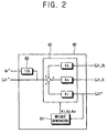
- Figure 2 illustrates a reference velocity calculator located in the apparatus of Figure 1 according to the exemplary embodiment of the present invention;
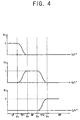
- Figures 3 and 4 illustrate a change of each weight output from the reference velocity calculator located in the apparatus of Figure 1 in accordance with a change of a command velocity; and
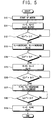
- Figure 5 is a control flowchart illustrating a method for controlling velocity according to an exemplary embodiment of the present invention.
- As shown in Figure 1, an apparatus 3 for controlling the velocity of a
motor 1 according to an exemplary embodiment of the present invention comprises aninverter 40, acurrent detector 50, avelocity estimator 60, asensing velocity calculator 70, areference velocity calculator 80, avelocity controller 10, acurrent controller 20, and avector controller 30. - The
motor 1 controlled by the apparatus 3 according to the exemplary embodiment of the present invention comprises at least one of a surface-mounted permanent magnet synchronous motor (SPMSM) and an interior permanent magnet synchronous motor (IPMSM). Themotor 1 operates in accordance with the power supplied from theinverter 40. - The
inverter 40 supplies the power to themotor 1. Theinverter 40 controls the rotational velocity of themotor 1 by controlling the current supplied to themotor 1, such as a three-phase current, on the basis of a voltage command signal from thevector controller 30. - The
current detector 50 detects the current passing through each of a plurality of output terminals of theinverter 40. Thecurrent detector 50 also generates a detection current vector Is on the basis of the detected currents at the output terminals of theinverter 40. The generated detection current vector Is is fed to thevelocity estimator 60. - The
current detector 50 may be provided in various configurations. For example, thecurrent detector 50 may directly detect all the three-phase currents of themotor 1 using a current transducer or a series shunt resistor. Also, thecurrent detector 50 may comprise two current transducers and two series shunt resistors, detect two phase currents of themotor 1 using the two current transducers and the two series shunt resistors, and estimate the remaining current on the basis of the detected two phase currents. - The
velocity estimator 60 receives the detection current vector Is output from thecurrent detector 50, and estimates and outputs an estimation velocity ωr_SL on the basis of the detection current vector Is. The estimation velocity ωr_SL output from thevelocity estimator 60 is input to thereference velocity calculator 80. - The
velocity estimator 60 generates the estimation velocity ωr_SL of themotor 1 on the basis of the positional error of the rotor of themotor 1. The positional error of the rotor is calculated by estimating the back electromotive force of themotor 1. For example, the back (or counter) electromotive force of themotor 1 may be calculated using a method for estimating the counter electromotive force as disclosed in "Sensorless control of interior permanent-magnet machine drives with zero-phase lag position estimation" by Hyun-bae Kim et al. (IEEE Transactions on Industry Applications, Volume: 39, Issue: 6, Nov.-Dec. 2003). - Alternatively, the
velocity estimator 60 may calculate the positional error of the rotor using a high frequency carrier signal. For example, the position error may be calculated by a method for calculating the position error of the rotor using the high frequency carrier signal disclosed in "Position estimation in induction machine utilizing rotor bar slot harmonics and carrier-frequency signal injection" by M.W. Wegner et al. (IEEE Transactions on Industry Applications, Volume 36, Issue 3, May-June 2000). - The
sensing velocity calculator 70 senses the rotational position of the rotor and calculates the sensing velocity ωr_S on the basis of the sensed rotational position of the rotor. The sensing velocity ωr_S calculated using thesensing velocity calculator 70 is input to thereference velocity calculator 80. Here, it is preferable but not essential to use a sensor having a low resolution, such as a Hall sensor for sensing the rotational position of the rotor used in thesensing velocity calculator 70. Having such a low resolution sensor reduces manufacturing costs. - The
reference velocity calculator 80 divides the overall velocity period of themotor 1 into a plurality of unit velocity periods on the basis of a command velocity ωr* for controlling the rotational velocity of themotor 1. The command velocity ωr* controls the rotational speed (or velocity) of themotor 1. Further, thereference velocity calculator 80 multiplies at least one of the command velocity ωr*, the sensing velocity ωr_S and the estimated velocity ωr_SL by a predetermined weight K1, K2 and K3, respectively. Then, thereference velocity calculator 80 calculates the sum of the sensing velocity ωr_S, the estimation velocity ωr_SL, and the command velocity ωr* as a reference estimation velocity ωr^ of themotor 1. Also, thereference velocity calculator 80 calculates a reference estimation position θr^ of themotor 1 on the basis of the reference estimation velocity ωr^. A method for calculating the reference estimation velocity ωr^ and/or the reference estimation position θr^ calculated by thereference velocity calculator 80 is described later. - A
comparator 90 compares the reference estimation velocity ωr^ output from thereference velocity calculator 80 with the command velocity ωr*, and outputs a comparison value indicative of the difference between the reference estimation velocity ωr^ and the command velocity ωr*. Then, thevelocity controller 10 generates a torque command Te* on the basis of the comparison value output from thecomparator 90 and outputs the torque command Te* to thecurrent controller 20. - The
current controller 20 receives the torque command Te* output from thevelocity controller 10 and outputs a voltage vector command V*. Thecurrent controller 20 receives an estimation current value (not shown) calculated while thevelocity estimator 60 estimates the estimation velocity ωr_SL, and generates the voltage vector command V* taking account of the estimation current value. - The
vector controller 30 receives the voltage vector command V* output from thecurrent controller 20 and the reference estimation position θr^ output from thereference velocity calculator 80 and outputs voltage command signals Va,b,c* corresponding to each phase of theinverter 40 on the basis of the voltage vector command V* and the reference estimation position θr^. - As shown in Figure 2, the
reference velocity calculator 80 according to the present invention comprises aweight generator 81 outputting the weights K1, K2 and K3 multiplied to the command velocity ωr*, the sensing velocity ωr_S and the estimation velocity ωr_SL and areference velocity generator 82 calculating the reference estimation velocity ωr^ after multiplying the command velocity ωr*, the sensing velocity ωr_S, and the estimation velocity ωr_SL by the weights K1, K2 and K3, respectively. Thereference velocity calculator 80 further comprises anintegrator 83 outputting the reference estimation position θr^. - The
reference velocity calculator 80 divides the overall velocity period of themotor 1 with the plurality of the unit velocity period. The unit velocity period comprises a low-speed period LP, a middle-speed period MP, a high-speed period HP, a first conversion period TP1 between the low-speed period LP and the middle-speed period MP and a second conversion period TP2 between the middle-speed period MP and the high-speed period HP. - The
weight generator 81 receives the command velocity ωr* and determines the present unit velocity period on the basis of the command velocity ωr*. For example, as shown in Figures 3 and 4, when the command velocity ωr* ranges between a zero velocity and a first velocity V1, theweight generator 81 determines the present unit velocity period as the low-speed period LP. In the same manner, theweight generator 81 determines the present unit period of velocity as the first conversion period TP1 when the command velocity ωr* ranges between the first velocity V1 and a second velocity V2, as the middle-speed period MP when the command velocity ωr* ranges between the second velocity V2 and a third velocity V3, as the second conversion period TP2 when the command velocity ωr* ranges between the third velocity V3 and a fourth velocity V4, and as the high-speed period HP when the command velocity ωr* is greater than the fourth velocity V4. - When the command velocity ωr* is in the range of the low-speed period LP, the
weight generator 81 sets a weight corresponding to the command velocity ωr* (hereinafter, referred to as "a command weight K1") as "1", sets a weight corresponding to the sensing velocity ωr_S (hereinafter, referred to as "a sensing weight K2") as "0" and sets a weight corresponding to the estimation velocity ωr_SL (hereinafter, referred to as "a estimation weight K3") as "0". Thus, the command velocity ωr* is output from thereference velocity calculator 80 as the reference estimation velocity ωr^ in the low-speed period LP. Thus, when themotor 1 initially starts, the reference the command velocity ωr* is output as the estimation velocity ωr^. This is because the calculation of the rotation velocity using the Hall sensor and sensorless control are difficult. - When the command velocity ωr* is in the range of the middle-speed period MP, the
weight generator 81 sets the sensing weight K2 sets as "1", sets the command weight K1 as "0" and sets the estimation weight K3 as "0". Thus, the sensing velocity ωr_S is output from thereference velocity calculator 80 as the reference estimation velocity ωr^ in the middle-speed period MP. Thus, it is possible to control themotor 1 on the basis of information from thesensing velocity calculator 70 during the middle-speed period MP in which it is difficult to control themotor 1 using sensorless control, but is possible to sense the rotational velocity of themotor 1 using the sensor having the low resolution. - When the command velocity ωr* is in the range of the high-speed period HP, the
weight generator 81 sets the estimation weight K3 as "1", sets the command weight K1 as "0" and sets the sensing weight K2 as "0". Thus, the estimation velocity ωr_SL is output from thereference velocity calculator 80 as the reference estimation velocity ωr^ at the high-speed period HP. Thus, it is possible to control themotor 1 using sensorless control, when themotor 1 operates at high speed over a predetermined speed. - When the command velocity ωr* is in the range of the first conversion period TP1, the
weight generator 81 multiplies the command velocity ωr* and the sensing velocity ωr_S by the command weight K1 and the sensing weight K2 varied according to the command velocity ωr*, respectively. Further, theweight generator 81 outputs the sum of the weighted command velocity ωr* and the weighted sensing velocity ωr_S as the reference estimation velocity ωr^. - When the command velocity ωr* enters the first conversion period TP1, the
weight generator 81 decreases the command weight K1 output as "1" at the low-speed period LP and increases the sensing weight K2 output as "0" at the low-speed period LP in accordance with an increase of the command velocity ωr*. Further, thereference velocity generator 82 multiplies the command weight K1 decreased in accordance with the increase of the command velocity ωr* by the command velocity ωr*, multiplies the sensing weight K2 increased in accordance with the increase of the command velocity ωr* by the sensing velocity ωr_S, and outputs the sum of the command velocity ωr* and the sensing velocity ωr_S as the reference estimation velocity ωr^. Thus, when the command velocity ωr* is changed from the low-speed period LP to the middle-speed period MP, the sudden change of the reference estimation velocity ωr^ due to the variation between the command velocity ωr* and the sensing velocity ωr_S is minimised. - When the command velocity ωr* enters the second conversion period TP2, the
weight generator 81 decreases the sensing weight K2 output as "1" in the middle-speed period MP and increases the estimation weight K3 output as "0" in the middle-speed period MP in accordance with an increase of the command velocity ωr*. Further, thereference velocity generator 82 multiplies the sensing velocity ωr_S by the sensing weight K2 decreased in accordance with the increase command velocity ωr*, multiplies the estimation velocity ωr_SL by the estimation weight K3 increased in accordance with the increase of the command velocity ωr*, and outputs the sum of the sensing velocity ωr_S and the estimation velocity ωr_SL as the reference estimation velocity ωr^. Thus, when the command velocity ωr* is changed from the middle-speed period MP to the high-speed period HP, a sudden change of the reference estimation velocity owing to the variation between the sensing velocity ωr_S and the estimation velocity ωr_SL is minimised. - In Figure 3, the
weight generator 81 increases and/or decreases each weight K1, K2 and K3 linearly during the first conversion period TP1 and the second conversion period TP2 in accordance with the increase of the command velocity ωr* for example. Further, in Figure 4, theweight generator 81 increases and/or decreases each weight K1, K2 and K3 sigmoidally in the first conversion period TP1 and the second conversion period TP2 in accordance with the increase of the command velocity ωr* as a further example. - Referring to Figure 5, when the
motor 1 initially starts at operation S10, theweight generator 81 outputs the command weight K1 as "1", the sensing weight K2 as "0", and the estimation weight K3 as "0" at operation S11. At this time, each weight K1, K2 and K3 output from theweight generator 81 is input to thereference velocity generator 82. Thereference velocity generator 82 multiplies the command velocity ωr*, the sensing velocity ωr_S, and the estimation velocity ωr_SL by weights K1, K2 and K3, respectively. Also, thereference velocity generator 82 outputs the sum of the command velocity ωr* multiplied by the command weight K1, the sensing velocity ωr_S multiplied by the sensing weight K2, and the estimation velocity ωr_SL multiplied by the estimation weight K3 as the reference estimation velocity ωr^. - Next, the
weight generator 81 determines whether the command velocity ωr* exceeds the first velocity V1 at operation S12. When the command velocity ωr* exceeds the first velocity V1, that is, the command velocity ωr* enters the first conversion period TP1, theweight generator 81 decreases the command weight K1 from "1", increases the sensing weight K2 from "0" in accordance with the increase in the command velocity ωr*, and sets estimation weight K3 to output as "0" at operation S13. - The
weight generator 81 then determines whether the command velocity ωr* exceeds the second velocity V2 at operation S14. Then, theweight generator 81 sets the sensing weight K2 as "1", sets the command weight K1 as "0" and sets the estimation weight K3 as "0", when the command velocity ωr* exceeds the second velocity V2, that is, the command velocity ωr* enters the middle-speed period MP, at operation S15. - Next, the
weight generator 81 determines whether the command velocity ωr* exceeds the third velocity V3 at operation S16. When the command velocity ωr* exceeds the third velocity V3, that is, the command velocity ωr* enters the second conversion period TP2, theweight generator 81 decreases the sensing weight K2 from "1", increases the estimation weight K3 from "0" in accordance with the increase of the command velocity ωr*, and sets the command weight K1 as "0", when the command velocity ωr* exceeds the third velocity V3, that is, enters the second conversion period TP2 at operation S17. - Next, the
weight generator 81 determines whether the command velocity ωr* exceeds the fourth velocity V4 at operation S18. Theweight generator 81 then sets the estimation weight K3 as "1", sets the command weight K1 as "0" and sets the sensing weight K2 as "0" when the command velocity ωr* exceeds the fourth velocity V4, that is, the command velocity ωr* enters the high-speed period HP at operation S19. Thus, it is possible that the reference estimation velocity ωr^ which is robust against a fluctuation of a disturbance torque at the start of themotor 1, and is accurate over the total velocity period of themotor 1, is calculated, before the rotation velocity of themotor 1 exceeds the fourth velocity V4 in which the sensorless control is feasible. - Although a few exemplary embodiments of the present invention have been shown and described, it will be appreciated by those skilled in the art that changes may be made in these exemplary embodiments without departing from the principles of the invention.
Claims (24)
- A speed controller (3) for a motor (1) having a rotor, the speed controller (3) operable to control the speed of the rotor in accordance with a reference estimated speed (ωr^) of the rotor, the controller (3) comprising:a speed sensing means (70) which senses the rotational position of the rotor, and calculates a sensed speed (ωr_S) in accordance with the sensed rotational position of the rotor;a speed estimator (60) which provides an estimated speed (ωr_SL) for the rotor in accordance with the position error of the rotor; anda reference speed calculator (80) for determining the reference estimated speed (ωr^) of the rotor in accordance with the sensed speed (ωr_S), the estimated speed (ωr_SL) or a command velocity (ωr*), wherein at least one of the sensed speed (ωr_S), the estimated speed (ωr_SL), and the command velocity (ωr*) has a weighting applied thereto.
- A speed controller (3) according to claim 1, wherein the reference speed calculator (80) is operable to generate the reference estimated speed (ωr_SL) of the rotor in accordance with the sum of the weighted sensed speed, the weighted estimated speed and the weighted command velocity.
- A speed controller (3) according to either one of claims 1 or 2, wherein the reference speed calculator (80) is operable to divide the total speed range of the rotor into a plurality of speed segments each speed segment being associated with the weightings applied to each of the sensed speed (ωr_S), the estimated speed (ωr_SL) and the command velocity (ωr*).
- The controller (3) according to claim 3, wherein the plurality of speed segments comprises:a low-speed segment (LP) in which the weighting for the command velocity (ωr*) is "1", and the weighting for the sensed speed (ωr_s) and the weighting for the estimated speed (ωr_SL) are "0";a middle-speed segment (MP) in which the weighting for the sensed speed (ωr_s) is "1", and the weighting for the command velocity (ωr*) and the weighting for the estimated speed (ωr_SL) are "0";a high-speed segment (HP) in which the weighting for the estimated speed (ωr_SL) is "1", and the weighting for the command velocity (ωr*) and the weighting for the sensed speed (ωr_s) are "0";a first conversion segment (TP1) between the low-speed segment (LP) and the middle-speed segment (MP); anda second conversion segment (TP2) between the middle-speed segment (MP) and the high-speed segment (HP).
- The controller (3) according to claim 4, wherein the reference speed calculator (80) calculates the sum of the command velocity (ωr*) and the sensed speed (ωr_s), and outputs the sum of the command velocity (ωr*) and the sensed speed (ωr_s) as the estimated reference speed (ωr^) in the first conversion segment (TP1).
- The controller (3) according to claim 5, wherein when the command velocity (ωr*) is in the first conversion segment (TP1), the reference speed calculator (80) decreases the weighting for the command velocity (ωr*) in accordance with an increase of the command velocity (ωr*), and increases the weighting for the sensed speed (ωr_s) in accordance with the increase of the command velocity (ωr*).
- The controller (3) according to claim 4, wherein the reference speed calculator (80) calculates the sum of the sensed speed (ωr_s) and the estimated speed (ωr_SL), and outputs the sum of the sensed speed (ωr_s) and the estimated speed (ωr_SL) as the estimated reference speed (ωr^) in the second conversion period (TP2).
- The controller (3) according to claim 7, wherein when the command velocity (ωr*) is in the second conversion segment (TP2), the reference speed calculator (80) decreases the weighting for the sensed speed (ωr_s) in accordance with an increase of the command velocity (ωr*), and increases the weighting for the estimated speed (ωr_SL) in accordance with the increase of the command velocity (ωr*).
- The controller (3) according to claim 6, wherein the reference speed calculator (80) linearly decreases the weighting for the command velocity (ωr*) and linearly increases the weighting for the sensed speed (ωr_s) in accordance with the increase of the command velocity (ωr*) in the first conversion segment (TP1).
- The controller according to claim 6, wherein the reference speed calculator (80) sigmoidally decreases the weighting for the command velocity (ωr*) and sigmoidally increases the weighting for the sensed speed (ωr_s) in accordance with the increase of the command velocity (ωr*) in the first conversion segment (TP1).
- The controller (3) according to claim 8, wherein the reference speed calculator (80) linearly decreases the weighting for the sensed speed (ωr_s) and linearly increases the weighting for the estimated speed (ωr_SL) in accordance with the increase of the command velocity (ωr*) in the second conversion segment (TP2).
- The controller (3) according to claim 8, wherein the reference speed calculator (80) sigmoidally decreases the weighting for the sensed speed (ωr_s) and sigmoidally increases the weighting for the estimated speed (ωr_SL) in accordance with the increase of the command velocity (ωr*) in the second conversion segment (TP2).
- A method of controlling the speed of a motor (1) having a rotor, wherein the speed of the rotor is controlled in accordance with a reference estimated speed (ωr^) of the rotor, the method comprising:sensing the rotational position of the rotor, and calculating a sensed speed (ωr_S) in accordance with the sensed rotational position of the rotor;providing an estimated speed (ωr_SL) for the rotor in accordance with the position error of the rotor; anddetermining the reference estimated speed (ωr^) of the rotor in accordance with the sensed speed (ωr_S), the estimated speed (ωr_SL) or a command velocity (ωr*), wherein at least one of the sensed speed (ωr_S), the estimated speed (ωr_SL), and the command velocity (ωr*) has a weighting applied thereto.
- A method according to claim 13, wherein the reference estimated speed (ωr_SL) of the rotor is generated in accordance with the sum of the weighted sensed speed, the weighted estimated speed and the weighted command velocity.
- A method according to either one of claims 13 or 14, comprising dividing the total speed range of the rotor into a plurality of speed segments each speed segment being associated with the weightings applied to each of the sensed speed (ωr_S), the estimated speed (ωr_SL) and the command velocity (ωr*).
- A method according to claim 15, wherein the plurality of speed segments comprises:a low-speed segment (LP) in which the weighting for the command velocity (ωr*) is "1", and the weighting for the sensed speed (ωr_s) and the weighting for the estimated speed (ωr_SL) are "0";a middle-speed segment (MP) in which the weighting for the sensed speed (ωr_s) is "1", and the weighting for the command velocity (ωr*) and the weighting for the estimated speed (ωr_SL) are "0";a high-speed segment (HP) in which the weighting for the estimated speed (ωr_SL) is "1", and the weighting for the command velocity (ωr*) and the weighting for the sensed speed (ωr_s) are "0";a first conversion segment (TP1) between the low-speed segment (LP) and the middle-speed segment (MP); anda second conversion segment (TP2) between the middle-speed segment (MP) and the high-speed segment (HP).
- The method according to claim 16, wherein the sum of the command velocity (ωr*) and the sensed speed (ωr_s) is calculated, and the sum of the command velocity (ωr*) and the sensed speed (ωr_s) is output as the estimated reference speed (ωr^) in the first conversion segment (TP1).
- The method according to claim 17, wherein when the command velocity (ωr*) is in the first conversion segment (TP1), the weighting for the command velocity (ωr*) is decreased in accordance with an increase of the command velocity (ωr*), and the weighting for the sensed speed (ωr_s) is increased in accordance with the increase of the command velocity (ωr*).
- The method according to claim 16, wherein the sum of the sensed speed (ωr_s) and the estimated speed (ωr_SL) is calculated, and the sum of the sensed speed (ωr_s) and the estimated speed (ωr_SL) is output as the estimated reference speed (ωr^) in the second conversion period (TP2).
- The method according to claim 19, wherein when the command velocity (ωr*) is in the second conversion segment (TP2), the weighting for the sensed speed (ωr_s) is decreased in accordance with an increase of the command velocity (ωr*), and the weighting for the estimated speed (ωr_SL) is increased in accordance with the increase of the command velocity (ωr*).
- The method according to claim 18, wherein the weighting for the command velocity (ωr*) is linearly decreased and the weighting for the sensed speed (ωr_s) is linearly increased in accordance with the increase of the command velocity (ωr*) in the first conversion segment (TP1).
- The method according to claim 18, wherein the weighting for the command velocity (ωr*) is sigmoidally decreased and the weighting for the sensed speed (ωr_s) is sigmoidally increased in accordance with the increase of the command velocity (ωr*) in the first conversion segment (TP1).
- The method according to claim 20, wherein the weighting for the sensed speed (ωr_s) is linearly decreased and the weighting for the estimated speed (ωr_SL) is linearly increased in accordance with the increase of the command velocity (ωr*) in the second conversion segment (TP2).
- The method according to claim 20, wherein the weighting for the sensed speed (ωr_s) is sigmoidally decreased and the weighting for the estimated speed (ωr_SL) is sigmoidally increased in accordance with the increase of the command velocity (ωr*) in the second conversion segment (TP2).
Applications Claiming Priority (1)
| Application Number | Priority Date | Filing Date | Title |
|---|---|---|---|
| KR1020040103251A KR100665061B1 (en) | 2004-12-08 | 2004-12-08 | Apparatus and method for control velocity of moter |
Publications (3)
| Publication Number | Publication Date |
|---|---|
| EP1684411A2 true EP1684411A2 (en) | 2006-07-26 |
| EP1684411A3 EP1684411A3 (en) | 2006-11-22 |
| EP1684411B1 EP1684411B1 (en) | 2009-04-08 |
Family
ID=36499553
Family Applications (1)
| Application Number | Title | Priority Date | Filing Date |
|---|---|---|---|
| EP05111269A Expired - Fee Related EP1684411B1 (en) | 2004-12-08 | 2005-11-24 | Motor control |
Country Status (5)
| Country | Link |
|---|---|
| US (1) | US7405534B2 (en) |
| EP (1) | EP1684411B1 (en) |
| KR (1) | KR100665061B1 (en) |
| CN (1) | CN100373767C (en) |
| DE (1) | DE602005013742D1 (en) |
Families Citing this family (9)
| Publication number | Priority date | Publication date | Assignee | Title |
|---|---|---|---|---|
| JP4847060B2 (en) * | 2005-07-15 | 2011-12-28 | 日立オートモティブシステムズ株式会社 | AC motor drive device and control method thereof |
| KR101330660B1 (en) * | 2006-09-08 | 2013-11-15 | 삼성전자주식회사 | Image forming apparatus capable of controlling scanning unit, method for controlling scanning unit thereof and motor control apparatus |
| JP4284355B2 (en) * | 2006-12-28 | 2009-06-24 | 株式会社日立産機システム | High response control device for permanent magnet motor |
| US20120146402A1 (en) * | 2010-12-09 | 2012-06-14 | Siemens Industry, Inc. | Control system for regulating bus voltage for an electric shovel |
| KR101228665B1 (en) * | 2011-12-21 | 2013-01-31 | 삼성전기주식회사 | Driving apparatus for motor and method thereof |
| KR20140116728A (en) * | 2013-03-25 | 2014-10-06 | 엘지전자 주식회사 | Apparatus and method for initially driving a sensorless bldc motor |
| US20150188461A1 (en) * | 2013-12-30 | 2015-07-02 | Samsung Electro-Mechanics Co., Ltd. | Motor driving control apparatus and method, and motor driving system using the same |
| CN111614301B (en) * | 2019-02-26 | 2022-01-04 | 达明机器人股份有限公司 | Dynamic sampling method of motor encoder |
| WO2021120100A1 (en) * | 2019-12-19 | 2021-06-24 | 瑞声声学科技(深圳)有限公司 | Electric motor signal control method, terminal device and storage medium |
Citations (1)
| Publication number | Priority date | Publication date | Assignee | Title |
|---|---|---|---|---|
| US6081093A (en) | 1996-12-05 | 2000-06-27 | Kabushiki Kaisha Yaskawa Denki | Sensorless control method and apparatus of permanent magnet synchronous motor |
Family Cites Families (22)
| Publication number | Priority date | Publication date | Assignee | Title |
|---|---|---|---|---|
| US5585709A (en) | 1993-12-22 | 1996-12-17 | Wisconsin Alumni Research Foundation | Method and apparatus for transducerless position and velocity estimation in drives for AC machines |
| JP3226253B2 (en) * | 1995-09-11 | 2001-11-05 | 株式会社東芝 | Control device for permanent magnet synchronous motor |
| JP3213796B2 (en) | 1995-12-15 | 2001-10-02 | 松下電器産業株式会社 | Servo motor controller |
| ES2193305T3 (en) | 1996-09-21 | 2003-11-01 | Diehl Ako Stiftung Gmbh & Co | INSTALLATION FOR THE CONTROL OF THE DRIVING CURRENT OF A PERMANENT MOTOR ELECTRIC SWITCHED. |
| JP3245098B2 (en) | 1997-09-03 | 2002-01-07 | 株式会社長田中央研究所 | Driving method of sensorless brushless DC motor |
| JPH11187699A (en) | 1997-12-24 | 1999-07-09 | Hitachi Ltd | Speed control method for induction motor |
| US6137258A (en) * | 1998-10-26 | 2000-10-24 | General Electric Company | System for speed-sensorless control of an induction machine |
| JP2001204190A (en) | 2000-01-17 | 2001-07-27 | Yaskawa Electric Corp | Device for estimating initial magnetic pole position and its error adjustment method |
| JP4403626B2 (en) | 2000-03-22 | 2010-01-27 | ダイキン工業株式会社 | SR motor sensorless control method and apparatus |
| US6552509B2 (en) * | 2000-05-10 | 2003-04-22 | Gti Electroproject B.V. | Method and a device for sensorless estimating the relative angular position between the stator and rotor of a three-phase synchronous motor |
| JP3832257B2 (en) * | 2001-02-26 | 2006-10-11 | 株式会社日立製作所 | Synchronous motor start control method and control device |
| KR100428505B1 (en) * | 2001-07-06 | 2004-04-28 | 삼성전자주식회사 | Method of speed speed and flux estimation for induction motor |
| KR100408061B1 (en) | 2001-07-09 | 2003-12-03 | 엘지전자 주식회사 | Rotor position detecting method for sensorless bldc motor |
| KR100431287B1 (en) | 2001-07-26 | 2004-05-12 | 동양기전 주식회사 | Method for starting sensorless brushless motor |
| JP3969093B2 (en) * | 2002-01-07 | 2007-08-29 | 松下電器産業株式会社 | Servo motor control device |
| KR100451227B1 (en) | 2002-02-05 | 2004-10-02 | 엘지전자 주식회사 | Method for sensorless rotary velocity control of synchronous reluctance motor |
| JP4370754B2 (en) * | 2002-04-02 | 2009-11-25 | 株式会社安川電機 | Sensorless control device and control method for AC motor |
| JP3695436B2 (en) * | 2002-09-18 | 2005-09-14 | 株式会社日立製作所 | Position sensorless motor control method and apparatus |
| KR100484819B1 (en) * | 2002-10-10 | 2005-04-22 | 엘지전자 주식회사 | Controlling System of Synchronous Reluctance Motoe |
| KR100511274B1 (en) | 2002-11-08 | 2005-08-31 | 엘지전자 주식회사 | Senseless control method for magnet type synchronous motor |
| US20040100220A1 (en) | 2002-11-25 | 2004-05-27 | Zhenxing Fu | Weighted higher-order proportional-integral current regulator for synchronous machines |
| KR20040097021A (en) * | 2004-10-12 | 2004-11-17 | 순천대학교 산학협력단 | Adaptive FNN Control System for High Performance of Induction Motor |
-
2004
- 2004-12-08 KR KR1020040103251A patent/KR100665061B1/en active IP Right Grant
-
2005
- 2005-11-01 US US11/262,846 patent/US7405534B2/en not_active Expired - Fee Related
- 2005-11-24 EP EP05111269A patent/EP1684411B1/en not_active Expired - Fee Related
- 2005-11-24 DE DE602005013742T patent/DE602005013742D1/en active Active
- 2005-12-05 CN CNB200510129503XA patent/CN100373767C/en not_active Expired - Fee Related
Patent Citations (1)
| Publication number | Priority date | Publication date | Assignee | Title |
|---|---|---|---|---|
| US6081093A (en) | 1996-12-05 | 2000-06-27 | Kabushiki Kaisha Yaskawa Denki | Sensorless control method and apparatus of permanent magnet synchronous motor |
Non-Patent Citations (2)
| Title |
|---|
| HYUN-BAE KIM: "Sensorless control of interior permanent-magnet machine drives with zero-phase lag position estimation", IEEE TRANSACTIONS ON INDUSTRY APPLICATIONS, vol. 39, November 2003 (2003-11-01) |
| M.W. WEGNER: "Position estimation in induction machine utilizing rotor bar slot harmonics and carrier-frequency signal injection", IEEE TRANSACTIONS ON INDUSTRY APPLICATIONS, vol. 36, May 2000 (2000-05-01) |
Also Published As
| Publication number | Publication date |
|---|---|
| US7405534B2 (en) | 2008-07-29 |
| EP1684411A3 (en) | 2006-11-22 |
| DE602005013742D1 (en) | 2009-05-20 |
| EP1684411B1 (en) | 2009-04-08 |
| CN100373767C (en) | 2008-03-05 |
| KR20060064407A (en) | 2006-06-13 |
| US20060119309A1 (en) | 2006-06-08 |
| KR100665061B1 (en) | 2007-01-09 |
| CN1787358A (en) | 2006-06-14 |
Similar Documents
| Publication | Publication Date | Title |
|---|---|---|
| EP1684411B1 (en) | Motor control | |
| JP3645509B2 (en) | Induction motor sensorless vector control system and sensorless vector control method | |
| Hurst et al. | Sensorless speed measurement using current harmonic spectral estimation in induction machine drives | |
| EP1850471B1 (en) | System and method for transient-based motor speed estimation with transient excitation | |
| JP5052723B2 (en) | Low ripple permanent magnet motor control | |
| US9825579B2 (en) | Temperature estimating apparatus for synchronous motor | |
| JP4221307B2 (en) | Synchronous motor control device, electrical equipment and module | |
| US10241130B2 (en) | Circuit and method to detect failure of speed estimation/speed measurement of a multi-phase AC motor | |
| Schroedl | Sensorless control of permanent magnet synchronous motors | |
| Hurst et al. | Speed sensorless field-oriented control of induction machines using current harmonic spectral estimation | |
| EP2706659A1 (en) | System for correcting an estimated position of a rotor of an electrical machine | |
| JP6667076B2 (en) | Motor control device and method of correcting torque constant in motor control device | |
| JP2002034278A (en) | Pole position detector for motor | |
| EP2493067B1 (en) | Method and apparatus for estimating rotor angle of synchronous reluctance motor | |
| US20020021105A1 (en) | Sensorless vector control apparatus and method thereof | |
| WO2016161213A1 (en) | Fractional delay adjustment in a field-oriented control architecture | |
| EP1755211A1 (en) | Resistance estimation of an AC electrical motor | |
| US20040060348A1 (en) | Method for detecting the magnetic flux the rotor position and/or the rotational speed | |
| KR20190036667A (en) | Motor Speed Estimation Apparatus and Motor Speed Estimation Method | |
| Hurst et al. | Sensorless speed measurement using current harmonic spectral estimation in induction machine drives | |
| US20040037541A1 (en) | BLDC motor speed control apparatus and method | |
| JP4127000B2 (en) | Motor control device | |
| KR100848155B1 (en) | Control method of the permanent magnet synchronous motor | |
| KR100561733B1 (en) | A sensorless control method of permanent magnet synchronous motor using an instantaneous reactive power | |
| KR101937958B1 (en) | Device for detecting error of sensorless motor using bemf signal |
Legal Events
| Date | Code | Title | Description |
|---|---|---|---|
| PUAI | Public reference made under article 153(3) epc to a published international application that has entered the european phase |
Free format text: ORIGINAL CODE: 0009012 |
|
| AK | Designated contracting states |
Kind code of ref document: A2 Designated state(s): AT BE BG CH CY CZ DE DK EE ES FI FR GB GR HU IE IS IT LI LT LU LV MC NL PL PT RO SE SI SK TR |
|
| AX | Request for extension of the european patent |
Extension state: AL BA HR MK YU |
|
| PUAL | Search report despatched |
Free format text: ORIGINAL CODE: 0009013 |
|
| AK | Designated contracting states |
Kind code of ref document: A3 Designated state(s): AT BE BG CH CY CZ DE DK EE ES FI FR GB GR HU IE IS IT LI LT LU LV MC NL PL PT RO SE SI SK TR |
|
| AX | Request for extension of the european patent |
Extension state: AL BA HR MK YU |
|
| RIC1 | Information provided on ipc code assigned before grant |
Ipc: G01P 3/489 20060101ALI20061018BHEP Ipc: H02P 23/14 20060101ALI20061018BHEP Ipc: H02P 21/14 20060101AFI20060616BHEP |
|
| 17P | Request for examination filed |
Effective date: 20070505 |
|
| 17Q | First examination report despatched |
Effective date: 20070608 |
|
| AKX | Designation fees paid |
Designated state(s): DE FR GB |
|
| GRAP | Despatch of communication of intention to grant a patent |
Free format text: ORIGINAL CODE: EPIDOSNIGR1 |
|
| RTI1 | Title (correction) |
Free format text: MOTOR CONTROL |
|
| RAP1 | Party data changed (applicant data changed or rights of an application transferred) |
Owner name: SAMSUNG ELECTRONICS CO., LTD. |
|
| GRAS | Grant fee paid |
Free format text: ORIGINAL CODE: EPIDOSNIGR3 |
|
| GRAA | (expected) grant |
Free format text: ORIGINAL CODE: 0009210 |
|
| AK | Designated contracting states |
Kind code of ref document: B1 Designated state(s): DE FR GB |
|
| REG | Reference to a national code |
Ref country code: GB Ref legal event code: FG4D |
|
| REF | Corresponds to: |
Ref document number: 602005013742 Country of ref document: DE Date of ref document: 20090520 Kind code of ref document: P |
|
| PLBE | No opposition filed within time limit |
Free format text: ORIGINAL CODE: 0009261 |
|
| STAA | Information on the status of an ep patent application or granted ep patent |
Free format text: STATUS: NO OPPOSITION FILED WITHIN TIME LIMIT |
|
| 26N | No opposition filed |
Effective date: 20100111 |
|
| REG | Reference to a national code |
Ref country code: FR Ref legal event code: PLFP Year of fee payment: 12 |
|
| REG | Reference to a national code |
Ref country code: FR Ref legal event code: PLFP Year of fee payment: 13 |
|
| PGFP | Annual fee paid to national office [announced via postgrant information from national office to epo] |
Ref country code: DE Payment date: 20171018 Year of fee payment: 13 Ref country code: FR Payment date: 20171020 Year of fee payment: 13 |
|
| PGFP | Annual fee paid to national office [announced via postgrant information from national office to epo] |
Ref country code: GB Payment date: 20171019 Year of fee payment: 13 |
|
| REG | Reference to a national code |
Ref country code: DE Ref legal event code: R119 Ref document number: 602005013742 Country of ref document: DE |
|
| GBPC | Gb: european patent ceased through non-payment of renewal fee |
Effective date: 20181124 |
|
| PG25 | Lapsed in a contracting state [announced via postgrant information from national office to epo] |
Ref country code: FR Free format text: LAPSE BECAUSE OF NON-PAYMENT OF DUE FEES Effective date: 20181130 Ref country code: DE Free format text: LAPSE BECAUSE OF NON-PAYMENT OF DUE FEES Effective date: 20190601 |
|
| PG25 | Lapsed in a contracting state [announced via postgrant information from national office to epo] |
Ref country code: GB Free format text: LAPSE BECAUSE OF NON-PAYMENT OF DUE FEES Effective date: 20181124 |