EP1684384A1 - Earthing device for cables with outer jacket - Google Patents
Earthing device for cables with outer jacket Download PDFInfo
- Publication number
- EP1684384A1 EP1684384A1 EP05290116A EP05290116A EP1684384A1 EP 1684384 A1 EP1684384 A1 EP 1684384A1 EP 05290116 A EP05290116 A EP 05290116A EP 05290116 A EP05290116 A EP 05290116A EP 1684384 A1 EP1684384 A1 EP 1684384A1
- Authority
- EP
- European Patent Office
- Prior art keywords
- connector
- connector body
- cable
- ground
- ground connector
- Prior art date
- Legal status (The legal status is an assumption and is not a legal conclusion. Google has not performed a legal analysis and makes no representation as to the accuracy of the status listed.)
- Granted
Links
- 239000004020 conductor Substances 0.000 claims abstract description 66
- 238000000034 method Methods 0.000 claims abstract description 15
- 238000005520 cutting process Methods 0.000 claims description 24
- 239000000463 material Substances 0.000 claims description 7
- 238000003825 pressing Methods 0.000 claims description 4
- 230000005489 elastic deformation Effects 0.000 claims description 3
- 230000004913 activation Effects 0.000 description 16
- 239000002184 metal Substances 0.000 description 9
- 229910052751 metal Inorganic materials 0.000 description 9
- 238000009434 installation Methods 0.000 description 5
- RYGMFSIKBFXOCR-UHFFFAOYSA-N Copper Chemical compound [Cu] RYGMFSIKBFXOCR-UHFFFAOYSA-N 0.000 description 3
- 229910052802 copper Inorganic materials 0.000 description 3
- 239000010949 copper Substances 0.000 description 3
- 238000004519 manufacturing process Methods 0.000 description 3
- 239000003989 dielectric material Substances 0.000 description 2
- 229920000914 Metallic fiber Polymers 0.000 description 1
- 210000005069 ears Anatomy 0.000 description 1
- 238000010915 one-step procedure Methods 0.000 description 1
- 230000001681 protective effect Effects 0.000 description 1
- 238000007789 sealing Methods 0.000 description 1
- 239000007787 solid Substances 0.000 description 1
- 125000006850 spacer group Chemical group 0.000 description 1
- 229910001220 stainless steel Inorganic materials 0.000 description 1
- 239000010935 stainless steel Substances 0.000 description 1
Images



Classifications
-
- H—ELECTRICITY
- H01—ELECTRIC ELEMENTS
- H01R—ELECTRICALLY-CONDUCTIVE CONNECTIONS; STRUCTURAL ASSOCIATIONS OF A PLURALITY OF MUTUALLY-INSULATED ELECTRICAL CONNECTING ELEMENTS; COUPLING DEVICES; CURRENT COLLECTORS
- H01R4/00—Electrically-conductive connections between two or more conductive members in direct contact, i.e. touching one another; Means for effecting or maintaining such contact; Electrically-conductive connections having two or more spaced connecting locations for conductors and using contact members penetrating insulation
- H01R4/58—Electrically-conductive connections between two or more conductive members in direct contact, i.e. touching one another; Means for effecting or maintaining such contact; Electrically-conductive connections having two or more spaced connecting locations for conductors and using contact members penetrating insulation characterised by the form or material of the contacting members
- H01R4/66—Connections with the terrestrial mass, e.g. earth plate, earth pin
-
- H—ELECTRICITY
- H01—ELECTRIC ELEMENTS
- H01R—ELECTRICALLY-CONDUCTIVE CONNECTIONS; STRUCTURAL ASSOCIATIONS OF A PLURALITY OF MUTUALLY-INSULATED ELECTRICAL CONNECTING ELEMENTS; COUPLING DEVICES; CURRENT COLLECTORS
- H01R9/00—Structural associations of a plurality of mutually-insulated electrical connecting elements, e.g. terminal strips or terminal blocks; Terminals or binding posts mounted upon a base or in a case; Bases therefor
- H01R9/03—Connectors arranged to contact a plurality of the conductors of a multiconductor cable, e.g. tapping connections
- H01R9/05—Connectors arranged to contact a plurality of the conductors of a multiconductor cable, e.g. tapping connections for coaxial cables
- H01R9/0512—Connections to an additional grounding conductor
Definitions
- the invention relates to a ground connector for earthing a cable, in particular a coaxial cable, wherein the cable has an outer jacket closely surrounding an inner conductor, the ground connector comprising a connector body, in particular a sleeve-type connector body, with at least one contact element for providing electrical contact between the connector body and the inner conductor of the cable.
- a ground connector of such a type is disclosed in WO 02/03501 A1.
- antennas are connected with receivers (such as a TV set) and transmitters via RF cables.
- the cables have a protective, electrically insulating outer jacket, typically made of plastic or rubber.
- This outer jacket closely surrounds an inner conductor made of metal, such as copper, but the outer jacket typically is not glued onto the inner conductor.
- the inner conductor is typically of tubular shape and houses a central conductor which is embedded in a dielectric.
- Grounding the cable i.e. installation of a ground connector
- the first step of this known procedure i.e. the removal of the outer jacket, is a rather time consuming step.
- the tools which may be expensive in acquisition, must be provided for every grounding operation.
- the metallic inner connector may be damaged at the removal of the outer jacket with a knife.
- ground connector of the type mentioned in the beginning, characterized in that the ground connector comprises at least one opening element so designed to cut and/or perforate the outer jacket.
- the basic idea of the invention is to save the first step of the installation procedure of known ground connectors.
- the installation is reduced to a one step procedure.
- the inventive ground connector is attached directly to the cable, without prior removal of the outer jacket.
- the inventive ground connector provides at least one opening element, such as a cutting edge, blade or a thorn, which cuts or perforates the outer jacket upon installation of the ground connector.
- the opening thus created allows the at least one contact element to access to the inner conductor.
- a special tool or a knife for removing the outer jacket are unnecessary.
- the contact area between the inner conductor and the contact element(s) is sufficiently large and the DC resistance between ground connector and cable is sufficiently low to fulfil the standards of lightning protection.
- the connector body is partly or entirely made of electrically conductive material, in particular a metal such as copper or stainless steel.
- the connector body may also be made of plastic coated with metal.
- the connector body has junction to a ground wire.
- the stiffness and strength of the opening element(s) and contact element(s) is advantageously chosen such that the outer jacket can be penetrated reliably, but the inner conductor cannot be damaged.
- the inventive ground connector i. e. the inventive device for grounding a cable
- the ground connector may comprise a shell type connector body so that it can clasp around the cable.
- the connector body has a shape at its inside substantially corresponding to the outer shape of the cable to be grounded.
- the shell type connector body has an opening at one side for imposing the ground connector on the cable at a midway section.
- a tab or ear is provided at both sides of the opening.
- the cable is preferably of circular shape, such as a standard coaxial cable.
- the cable may also have other shapes, i.e. cross sections, such as a rectangular shape.
- the sleeve-type connector body may be made of one elastically deformable part or of two half shells connected by a joint, for example.
- the inventive ground connector can be provided with sealings, and in particular with a waterproof shell body, for preventing the intrusion of humidity to the contact area. Then the ground connector is suitable for outdoor applications.
- the typical kind of cable to be contacted is an RF cable, in particular a coaxial cable with a round cross section.
- RF cable in particular a coaxial cable with a round cross section.
- all types of RF cables are suitable for use with the invention.
- the opening elements and the contact elements are typically evenly distributed on the connector body.
- the contact elements are arranged pairwise opposite to each other, what guarantees a constant contact pressure.
- other means for providing a constant contact pressure of the contact elements can be used.
- a similar arrangement is advantageous for the opening elements in order to achieve a uniform cutting or perforation of the outer jacket.
- the at least one opening element and the at least one contact element are identical parts of the ground connector.
- the at least one opening element serves as a contact element, too, and there is no separate contact element apart from the at least one multifunctional opening element.
- each element can be more specialized to its function.
- a highly preferred embodiment of the inventive ground connector is characterized in that the ground connector comprises a sleeve-type connector body, that the at least one opening element is positioned at the inside of the connector body, and that the at least one opening element comprises a blade inclined with respect to the radial direction of the connector body.
- the blades can cut the outer jacket of the cable. This embodiment is easy to manufacture.
- the connector body is made of a sheet metal, and the blade or blades are manufactured by stamping the sheet metal.
- the radial direction is defined by the normal with respect to the local face of the inside of the connector body where the blade is fixed to the connector body.
- the cable and the connector body have an annular cross-section in this embodiment, the radial direction is directed towards the center of the connector body (or, in the mounted state, towards the center axis of the cable), and the cutting edges of the blades are in parallel with a center axis if the cable.
- Typical angles of the blade with respect to the radial direction are 25° through 50°.
- the extension of the blades in the radial direction preferably corresponds to the thickness of the outer jacket of the cable in order to protect the inner conductor during installation of the inventive ground connector.
- a further development of this embodiment is characterized in that the at least one contact element is positioned at the inside of the connector body, that the contact element protrudes radially inwards with respect to the connector body, that the contact element can be moved towards the inside face of the connector body by elastic deformation.
- the blades peel off the outer jacket from the inner conductor, and the contact element or contact elements bear on the inner conductor. In that position, the inner conductor elastically deforms the contact elements, i.e. the inner conductor pushes the contact elements radially outwards towards the inside of the connector body, resulting in an elastic contact pressure of the contact elements on the inner conductor. This design guarantees good electrical contact.
- the ground connector comprises only one opening element
- the ground connector further comprises an annular shell body surrounding the connector body, but leaving an annular gap between the outside face of the connector body and the shell body for housing detached material of the outer jacket
- the contact element is elastically prestressed radially inwards by a spring element.
- the spring element in particular comprising a leaf spring, increases the contact pressure of the contact element or the contact elements to the inner connector.
- the ground connector comprises an annular connector body and an annular shell body surrounding the connector body, that the shell body is twistable against the connector body, that the at least one opening element is movable in a radial direction, that the opening element has an inclined outer face, that the shell body comprises at least one recess for housing the at least one opening element in a radially outer position, and that the opening element has a cutting edge at its radially inner side.
- the ground connector i.e. a twist of the connector body with respect to the shell body, the movable opening element is forced to move radially inwards towards the cable, i.e.
- the movable opening element or elements preferably serve as contact elements, too. Then the twisted (or activated) position of connector body and shell body also provides a high contact pressure and thus a good electrical contact between inner conductor and the movable opening elements.
- an inclined inner face of the recess of the shell body may force the movable opening element radially inwards upon activation.
- both the movable opening element and the recess have inclined faces for better stability.
- the ground connector comprises a sleeve-type connector body, that the at least one opening element is positioned at the inside of the connector body, and that the at least one opening element comprises a cutting edge or a needlepoint directed inwards in the radial direction of the connector body.
- the ground connector comprises a sleeve-type connector body, that the at least one opening element is positioned at the inside of the connector body, and that the at least one opening element comprises a cutting edge or a needlepoint directed inwards in the radial direction of the connector body.
- a corresponding embodiment will be discussed with reference to Fig. 3a, 3b.
- This embodiment is extremely simple to manufacture and to install.
- the cutting edges or needle points pierce the outer jacket upon activation and contact the inner conductor as contact elements.
- the extension of the opening elements preferably corresponds to the thickness of the outer jacket of the cable to be grounded in order to protect the inner conductor.
- the invention also comprises a method for earthing a cable, in particular a coaxial cable, wherein the cable has an outer jacket surrounding an inner conductor, characterized in that
- a ground connector is installed in a two step procedure, see above.
- the ground connector of the state of the art is collocated over an uncovered part of the inner conductor of the cable.
- the inventive method simplifies this procedure by omitting the first step of removal of the outer jacket prior to attachment of the ground connector.
- the outer jacket is cut or perforated when the ground connector is already attached to the cable to be grounded.
- the inventive ground connector itself provides means for this purpose.
- the outer jacket Upon activation, in particular rotation, exerting pressure of shifting the ground connector with respect to the cable, the outer jacket is opened and direct contact between the inner conductor of the cable and the connector body, i.e. its connecting element or elements, is established.
- a suitable inventive ground connector is activated by rotating the connector body in the direction where the blade of the at least one opening element is pointing towards.
- the cutting edge of the blade is then forced into the outer jacket of the cable. It may be useful to exert radial pressure together with the rotational movement in order to lead the cutting edge deeper into the outer jacket. The rotational movement is easy to perform and can be accomplished even by untrained personnel.
- This variant is useful with annular (i.e. circular) shaped connector bodies and opening elements comprising an inclined blade at its inside.
- a suitable inventive ground connector is activated by rotating the shell body against the connector body in the direction in which the stretch of the movable opening element in the radial direction increases.
- the rotation forces the movable opening element into the outer jacket and onto the inner conductor of the cable.
- the rotational movement is easy to perform and can be accomplished even by untrained personnel. This method is useful with ground connectors comprising opening elements movable in a radial direction.
- the ground connector is activated by applying radial pressure to the connector body, in particular by pressing together two tabs of the sleeve-type connector body. Pressing together two tabs, e.g. by turning a screw, is extremely easy to perform and can be accomplished even by untrained personnel.
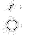
- Fig. 1a shows a cable 11 and an inventive ground connector 12 clasping around the cable 11 before activation of the ground connector 12 in a schematic cross-sectional view perpendicular to the extension of the cable 11.
- the ground connector 12 comprises a connector body 13.
- the connector body 13 is circular (or annular) in shape.
- the connector body 13 is surrounded by a shell body 14.
- the connector body 13 has an opening 15c at one side, which is limited by two tabs (or ears) 15a, 15b.
- the connector body 13 further comprises several opening elements 16 in the shape of a blade. Each blade has a cutting edge at its end.
- the cable 11 comprises an outer jacket 17, typically made of plastic, and an inner conductor 18, typically made of metal.
- the outer jacket 17 is situated directly on the inner conductor 18, but it is not glued onto the inner conductor 18.
- Fig. 1 a the inner structure of the cable 11 inside the inner conductor 18 is not shown for simplification (compare Fig. 6 for details).
- the blades direct at the outer jacket 17 at an angle ⁇ with respect to the radial direction which is perpendicular to the local inside face 19 of the connector body 13 where the blade is fixed to the connector body 13.
- Fig. 1b shows part of the ground connector 12 and the cable 11 in an activated state.
- the opening elements 16 have carved into the outer jacket 17 and peeled off some of the outer jacket material.
- the connector body 13 has openings broad enough to let the peeled off material move through; sufficient openings are automatically created when manufacturing the blades by stamping from a sheet metal connector body.
- each opening element 16 contacts the inner conductor 18 with a flat face 16a facing towards the inner conductor 18 and adjacent to the cutting edge of the opening element 16.
- the flat face 16a is roughly parallel to the corresponding local inside face 19 of the connector body 13; tolerances may be balanced by elastic deformation of the opening elements 16, if necessary.
- the opening elements 16 also act as contact elements.
- Fig. 2a shows parts of a cable 11 and an inventive ground connector 21, both of circular shape, before activation.
- the ground connector 21 comprises a connector body 22 and a shell body 23.
- the connector body 22 comprises an opening element 24 which is movable in a radial direction r and guided by the connector body 22. At its inner side, the opening element 24 has a cutting edge 25, whereas an outer face 26 of the opening element 24 is inclined with respect to the local circumferential direction of the connector body 22.
- the shell body 23 has a recess 27 for housing the opening element 24 in the non-activated state, i.e. when the opening element 24 is in a radially outer position. The shape of the recess 27 corresponds to the shape of the outer face 26 of the opening element 24.
- the shell body 23 In order to activate the ground connector 21, i.e. for establishing an electrical contact between the connector body 22 and the inner conductor 18 of the cable 11, the shell body 23 is rotated against the connector body 22.
- the rotation direction of the shell body 23 with respect to the connector body 22 is towards the direction in which the radial extension of the opening element 24 or of the recess 27, respectively, increases, here counterclockwise.
- the resultant state is shown in Fig. 2b.
- the shell body 23 and the recess 27 rotate away from the opening element 24, the space for housing the opening element 24 vanishes.
- the opening element 24 has to move radially inwards, i.e. through the outer jacket 17 and towards the inner conductor 18.
- the cutting edge 25 cuts the outer jacket 17 of the cable 11.
- the cutting edge 25 of the opening element 24 is pressed upon the inner conductor 18, establishing an electrical contact between the inner conductor 18 and the connector body 22.
- the opening element 24 in Fig. 2a, 2b acts as a contact element.
- the connector body 22 may comprise fixing means such as a catch at the inside of the connector body 22.
- Fig. 3a shows schematically a cable 11 and another inventive ground connector 31 with a shell-type connector body 32 before activation.
- the connector body 32 comprises several opening elements 33 which narrow towards their ends where they have cutting edges. These cutting edges extend perpendicular to the plane of the drawing, i.e. in parallel to the extension of the cable 11, so they give a thorn-like cross-section in Fig. 3a.
- the cutting edges are directed perpendicularly away from the local inside face of the connector body 32. In other words, they are directed towards the center of the cable 11, i.e. radially inwards.
- the cutting edges When exerting a radial pressure onto the connector body 32, in particular by pressing together two tabs 15a, 15b of the connector body 32, the cutting edges perforate the outer jacket 17 of the cable 11. In the activated state, the cutting edges and thus the opening elements 33 touch the inner conductor 18, see Fig. 3b. So again, the opening elements 33 serve as contact elements in this embodiment of the invention.
- the tabs 15a, 15b may have a mechanical stop in order to maintain a minimum distance from each other and thus a minimum radius of the connector body 32.
- Fig. 4a shows parts of an improved inventive ground connector 41 based on the embodiment of Fig. 1 a, 1 b, together with a cable 11 to be contacted, before activation.
- a separate contact element 43 is provided at the inside of the connector body 13, for each opening element 42 (comparable to the opening elements 16 of Fig. 1 a, 1 b).
- the contact element 43 is located behind the opening element 42.
- the contact element 43 protrudes radially inwards towards the center of the connector body 13 or the center of the cable 11, but it is elastically flexible in the radial direction.
- Fig. 4b shows such an activated state.
- the contact area between inner conductor 18 and connector body 13 is increased, compared with a contact established by the opening elements 42 alone as in Fig. 1 a, 1 b. Due to its elastic behavior, the contact element 43 touches the inner conductor 18 with some contact pressure, in particular more contact pressure than the opening elements 42. Thus the electrical contact as a whole is improved. Note that the contact pressure of the opening element 42 may be limited with respect to the danger of damaging the inner conductor 18 with the cutting edge at the tip of the opening element 42.
- the embodiment of Fig. 5a is based on the embodiments of Fig. 1a, 1b, 4a, 4b.
- An inventive ground connector 51 surrounds a cable 11 to be grounded.
- the ground connector comprises a connector body 52 and a shell body 53, both annular in shape.
- the connector body 52 comprises two tabs 15a, 15b, one opening element, 54 (comparable to the opening element 16 in Fig. 1a), one contact element 55 and a spring element 56.
- the spring element 56 presses the contact element 55 radially inward, so that the contact element 55 rests on the outer jacket 17 of the cable 11 with a significant contact pressure.
- the ground connector 51 is activated by rotating the connector body 52 clockwise with respect to the cable 11, and concurrently tightening the connector body 52 (i.e. exerting radial pressure).
- Fig. 5b shows the activated state, after about a 120° rotation of the connector body 52.
- the opening element 54 has cut the outer jacket 17 and removed it partially from the inner conductor 18.
- the connector body 52 In front of the opening element 42, the connector body 52 has an opening large enough to let the outer jacket material 58 pass.
- the contact element 55 is now pressed onto the uncovered inner conductor 18 of the cable 11 by the spring element 56, so good electrical contact is established.
- a defined (and in particular a high) contact pressure can be chosen.
- the contact element 55 has a section with a radius of curvature corresponding to the radius of curvature of the inner conductor, so a large contact area can be used.
- the contact element 55 may be designed as a braid of copper.
- an inventive ground connector comprises a connector body with at least one opening element designed like a fork.
- the prongs of the at least one opening element pierce the outer jacket and contact the inner conductor of the cable.
- the prongs have flattened sections adjusted for contacting the inner conductor, preferably tangentially.
- Fig. 6 shows the end of a typical coaxial cable 11 of the state of the art in a schematic view.
- a coaxial cable 11 can be grounded with an inventive ground connector as shown in Figs. 1a through 5b at a midway section of the cable 11.
- the coaxial cable 11 has an outer jacket 17 made of plastic which closely surrounds an inner conductor 18.
- the inner conductor 18 is typically made of solid metal or a metallic braid (woven from metallic threads) for high flexibility.
- a dielectric material 62 is provided between the inner conductor 18 and the central conductor 61. Sometimes the dielectric is replaced by spacers (and air).
- the dimensions of the inner conductor 18 and the central conductor 61 as well as the characteristics of the dielectric material 62 are chosen such that a defined wave resistance of the coaxial cable 11, such as 50 Ohm for example, is obtained.
- the invention provides a device for grounding an RF cable in particular at a midway section.
- the device (or ground connector) is attached to the cable without preparing the cable in any way, in particular the cable still has its outer jacket (or external jacket) then.
- the ground connector has built in mechanical means for uncovering an inner conductor (or internal conductor) of the cable which are called opening element(s).
- the device has built in mechanical means for establishing an electrical contact between the ground connector and the inner conductor of the cable which are called contact element(s).
- the means for uncovering the inner conductor and the means for establishing the electrical contact may be identical in order to simplify the ground connector. The uncovering of the inner conductor is performed automatically when installing the ground connector, thus saving time, effort and costs at earthing the RF cable.
Landscapes
- Cable Accessories (AREA)
- Coupling Device And Connection With Printed Circuit (AREA)
- Details Of Connecting Devices For Male And Female Coupling (AREA)
- Insulated Conductors (AREA)
- Multi-Conductor Connections (AREA)
Abstract
Description
- The invention relates to a ground connector for earthing a cable, in particular a coaxial cable, wherein the cable has an outer jacket closely surrounding an inner conductor,
the ground connector comprising a connector body, in particular a sleeve-type connector body, with at least one contact element for providing electrical contact between the connector body and the inner conductor of the cable. - A ground connector of such a type is disclosed in WO 02/03501 A1.
- Radio frequency (=RF) cables are used in numerous applications, e.g. in mobile radio telephone service, broadcasting service or beam radio. In particular, antennas are connected with receivers (such as a TV set) and transmitters via RF cables.
- In order to protect users and buildings, it is necessary to ground these cables.
- The cables have a protective, electrically insulating outer jacket, typically made of plastic or rubber. This outer jacket closely surrounds an inner conductor made of metal, such as copper, but the outer jacket typically is not glued onto the inner conductor. The inner conductor is typically of tubular shape and houses a central conductor which is embedded in a dielectric.
- Grounding the cable, i.e. installation of a ground connector, is a two step procedure in the state of the art. First, the outer jacket is removed at a defined length. This removal is accomplished by means of special tools or a simple knife in manual operation. Second, after the inner conductor has been uncovered, the known ground connector is attached to the cable, and contact is established between the uncovered inner conductor and the ground connector.
- The first step of this known procedure, i.e. the removal of the outer jacket, is a rather time consuming step. The tools, which may be expensive in acquisition, must be provided for every grounding operation. Further, the metallic inner connector may be damaged at the removal of the outer jacket with a knife.
- It is the object of the present invention to provide a ground connector which is easier to install than known ground connectors.
- This object is achieved, by means of the invention, by a ground connector of the type mentioned in the beginning, characterized in that the ground connector comprises at least one opening element so designed to cut and/or perforate the outer jacket.
- The basic idea of the invention is to save the first step of the installation procedure of known ground connectors. With the inventive ground connector, the installation is reduced to a one step procedure. The inventive ground connector is attached directly to the cable, without prior removal of the outer jacket. The inventive ground connector provides at least one opening element, such as a cutting edge, blade or a thorn, which cuts or perforates the outer jacket upon installation of the ground connector. The opening thus created allows the at least one contact element to access to the inner conductor. A special tool or a knife for removing the outer jacket are unnecessary. By means of the invention, a simple, cost-efficient, fast and safe grounding of a cable is achieved.
- When installed, in accordance with the invention, the contact area between the inner conductor and the contact element(s) is sufficiently large and the DC resistance between ground connector and cable is sufficiently low to fulfil the standards of lightning protection.
- The connector body is partly or entirely made of electrically conductive material, in particular a metal such as copper or stainless steel. The connector body may also be made of plastic coated with metal. The connector body has junction to a ground wire.
- The stiffness and strength of the opening element(s) and contact element(s) is advantageously chosen such that the outer jacket can be penetrated reliably, but the inner conductor cannot be damaged.
- The inventive ground connector, i. e. the inventive device for grounding a cable, may be installed equally well at an end of a cable, or at a midway section of the cable, because it is attached directly to the outer jacket.
- The ground connector may comprise a shell type connector body so that it can clasp around the cable. For this purpose, the connector body has a shape at its inside substantially corresponding to the outer shape of the cable to be grounded. Preferably, the shell type connector body has an opening at one side for imposing the ground connector on the cable at a midway section. At both sides of the opening, a tab (or ear) is provided. By putting the tabs closer together, e.g. by turning a screw held in an opening and a thread of the respective tabs, the connector body can be tightened around the cable. This guarantees a safe fastening of the ground connector. The cable is preferably of circular shape, such as a standard coaxial cable. However, the cable may also have other shapes, i.e. cross sections, such as a rectangular shape. The sleeve-type connector body may be made of one elastically deformable part or of two half shells connected by a joint, for example.
- The inventive ground connector can be provided with sealings, and in particular with a waterproof shell body, for preventing the intrusion of humidity to the contact area. Then the ground connector is suitable for outdoor applications.
- The typical kind of cable to be contacted is an RF cable, in particular a coaxial cable with a round cross section. However, all types of RF cables are suitable for use with the invention.
- Preferably, there are several opening elements and several contact elements. The opening elements and the contact elements are typically evenly distributed on the connector body. Advantageously, the contact elements are arranged pairwise opposite to each other, what guarantees a constant contact pressure. However, other means for providing a constant contact pressure of the contact elements can be used. A similar arrangement is advantageous for the opening elements in order to achieve a uniform cutting or perforation of the outer jacket.
- In a preferred embodiment of the inventive ground connector, the at least one opening element and the at least one contact element are identical parts of the ground connector. The at least one opening element serves as a contact element, too, and there is no separate contact element apart from the at least one multifunctional opening element. There may be one multifunctional opening element or several multifunctional opening elements. This embodiment simplifies the design of the inventive ground connector. However, in the alternative case also covered by the invention, when the opening element(s) and contact element(s) are separate parts, each element can be more specialized to its function.
- A highly preferred embodiment of the inventive ground connector is characterized in that the ground connector comprises a sleeve-type connector body, that the at least one opening element is positioned at the inside of the connector body, and that the at least one opening element comprises a blade inclined with respect to the radial direction of the connector body. A corresponding embodiment will be discussed with reference to Fig. 1 a, 1 b. The blades can cut the outer jacket of the cable. This embodiment is easy to manufacture. Preferably, the connector body is made of a sheet metal, and the blade or blades are manufactured by stamping the sheet metal. The radial direction is defined by the normal with respect to the local face of the inside of the connector body where the blade is fixed to the connector body. Typically, the cable and the connector body have an annular cross-section in this embodiment, the radial direction is directed towards the center of the connector body (or, in the mounted state, towards the center axis of the cable), and the cutting edges of the blades are in parallel with a center axis if the cable. Typical angles of the blade with respect to the radial direction are 25° through 50°. Through a twisting movement of the connector body around the cable, the blades carve with their cutting edges into the outer jacket. In case of non-annular shapes, a shifting movement of the connector body along the cable may replace the twisting movement. The extension of the blades in the radial direction preferably corresponds to the thickness of the outer jacket of the cable in order to protect the inner conductor during installation of the inventive ground connector.
- A further development of this embodiment is characterized in that the at least one contact element is positioned at the inside of the connector body, that the contact element protrudes radially inwards with respect to the connector body, that the contact element can be moved towards the inside face of the connector body by elastic deformation. A corresponding design will be discussed with reference to Fig. 4a, 4b. In this embodiment, the blades peel off the outer jacket from the inner conductor, and the contact element or contact elements bear on the inner conductor. In that position, the inner conductor elastically deforms the contact elements, i.e. the inner conductor pushes the contact elements radially outwards towards the inside of the connector body, resulting in an elastic contact pressure of the contact elements on the inner conductor. This design guarantees good electrical contact.
- A further development of the former further development is characterized in that the ground connector comprises only one opening element, that the ground connector further comprises an annular shell body surrounding the connector body, but leaving an annular gap between the outside face of the connector body and the shell body for housing detached material of the outer jacket, and that the contact element is elastically prestressed radially inwards by a spring element. A corresponding design will be discussed with reference to Fig. 5a, 5b. This design allows the peeling off of the outer jacket at one piece. The peeled-off outer jacket can be stored in the annular gap. The spring element, in particular comprising a leaf spring, increases the contact pressure of the contact element or the contact elements to the inner connector.
- Another advantageous embodiment of the inventive ground connector is characterized in that the ground connector comprises an annular connector body and an annular shell body surrounding the connector body, that the shell body is twistable against the connector body, that the at least one opening element is movable in a radial direction, that the opening element has an inclined outer face, that the shell body comprises at least one recess for housing the at least one opening element in a radially outer position, and that the opening element has a cutting edge at its radially inner side. A corresponding embodiment will be discussed with reference to Fig. 2a, 2b. Upon activation of the ground connector, i.e. a twist of the connector body with respect to the shell body, the movable opening element is forced to move radially inwards towards the cable, i.e. from the outer position into a perforating position. The cutting edge carves through the outer jacket. In this embodiment, the movable opening element or elements preferably serve as contact elements, too. Then the twisted (or activated) position of connector body and shell body also provides a high contact pressure and thus a good electrical contact between inner conductor and the movable opening elements. Alternative to an inclined outer face of the movable opening element, and in accordance with the invention, an inclined inner face of the recess of the shell body may force the movable opening element radially inwards upon activation. Preferably, both the movable opening element and the recess have inclined faces for better stability.
- Another preferred embodiment of the invention is characterized in that the ground connector comprises a sleeve-type connector body, that the at least one opening element is positioned at the inside of the connector body, and that the at least one opening element comprises a cutting edge or a needlepoint directed inwards in the radial direction of the connector body. A corresponding embodiment will be discussed with reference to Fig. 3a, 3b. This embodiment is extremely simple to manufacture and to install. The cutting edges or needle points pierce the outer jacket upon activation and contact the inner conductor as contact elements. Again, the extension of the opening elements preferably corresponds to the thickness of the outer jacket of the cable to be grounded in order to protect the inner conductor.
- The invention also comprises a method for earthing a cable, in particular a coaxial cable, wherein the cable has an outer jacket surrounding an inner conductor, characterized in that
- a) an inventive ground connector is collocated over the outer jacket of the cable,
- b) that the ground connector is activated, in particular by a rotational movement of the connector body and/or by applying a radial pressure to the connector body, such that the at least one opening element cuts and/or perforates the outer jacket and the at least one contact element contacts the inner conductor.
- In the state of the art, a ground connector is installed in a two step procedure, see above. In particular, the ground connector of the state of the art is collocated over an uncovered part of the inner conductor of the cable. The inventive method simplifies this procedure by omitting the first step of removal of the outer jacket prior to attachment of the ground connector. By means of the invention, the outer jacket is cut or perforated when the ground connector is already attached to the cable to be grounded. The inventive ground connector itself provides means for this purpose. Upon activation, in particular rotation, exerting pressure of shifting the ground connector with respect to the cable, the outer jacket is opened and direct contact between the inner conductor of the cable and the connector body, i.e. its connecting element or elements, is established.
- In a preferred variant of the inventive method, a suitable inventive ground connector is activated by rotating the connector body in the direction where the blade of the at least one opening element is pointing towards. The cutting edge of the blade is then forced into the outer jacket of the cable. It may be useful to exert radial pressure together with the rotational movement in order to lead the cutting edge deeper into the outer jacket. The rotational movement is easy to perform and can be accomplished even by untrained personnel. This variant is useful with annular (i.e. circular) shaped connector bodies and opening elements comprising an inclined blade at its inside.
- In another preferred variant of the inventive method, a suitable inventive ground connector is activated by rotating the shell body against the connector body in the direction in which the stretch of the movable opening element in the radial direction increases. The rotation forces the movable opening element into the outer jacket and onto the inner conductor of the cable. The rotational movement is easy to perform and can be accomplished even by untrained personnel. This method is useful with ground connectors comprising opening elements movable in a radial direction.
- In an advantageous variant of the inventive method for use with a suitable inventive ground connector, the ground connector is activated by applying radial pressure to the connector body, in particular by pressing together two tabs of the sleeve-type connector body. Pressing together two tabs, e.g. by turning a screw, is extremely easy to perform and can be accomplished even by untrained personnel.
- Further advantages can be extracted from the description and the enclosed drawing. The features mentioned above and below can be used in accordance with the invention either individually or collectively in any combination. The embodiments mentioned are not to be understood as exhaustive enumeration but rather have exemplary character for the description of the invention.
- The invention is shown in the drawing.
- Fig. 1 a
- shows an inventive ground connector attached to a cable before activation, wherein the connector body comprises seven blade-shaped opening elements at its inside.
- Fig. 1b
- shows the ground connector of Fig. 1 a in an activated state.
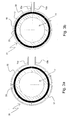
- Fig. 2a
- shows parts of an inventive ground connector attached to a cable before activation, wherein the connector body comprises a radially movable opening element.
- Fig. 2b
- shows the ground connector of Fig. 2a in an activated state.
- Fig. 3a
- shows an inventive ground connector attached to a cable before activation, wherein the connector body comprises seven thorn-shaped opening elements.
- Fig. 3b
- shows the ground connector of Fig. 3a in an activated state.
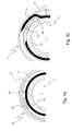
- Fig. 4a
- shows parts of an inventive ground connector attached to a cable before activation, wherein the connector body comprises a blade shaped opening element and a separate contact element.
- Fig. 4b
- shows the ground connector of Fig. 4a in an activated state.
- Fig. 5a
- shows an inventive ground connector attached to a cable before activation, wherein the connector body comprises one blade shaped opening element and a separate contact element supported by a leaf spring.
- Fig. 5b
- shows the ground connector of Fig. 5a in an activated state, wherein the peeled-off outer jacket is stored in an annular gap.
- Fig. 6
- shows the cross section of a typical coaxial cable of the state of the art for use with the invention.
- Fig. 1a shows a
cable 11 and aninventive ground connector 12 clasping around thecable 11 before activation of theground connector 12 in a schematic cross-sectional view perpendicular to the extension of thecable 11. - The
ground connector 12 comprises aconnector body 13. Theconnector body 13 is circular (or annular) in shape. Theconnector body 13 is surrounded by ashell body 14. Theconnector body 13 has anopening 15c at one side, which is limited by two tabs (or ears) 15a, 15b. Theconnector body 13 further comprises several openingelements 16 in the shape of a blade. Each blade has a cutting edge at its end. - The
cable 11 comprises anouter jacket 17, typically made of plastic, and aninner conductor 18, typically made of metal. Theouter jacket 17 is situated directly on theinner conductor 18, but it is not glued onto theinner conductor 18. In Fig. 1 a the inner structure of thecable 11 inside theinner conductor 18 is not shown for simplification (compare Fig. 6 for details). - The blades direct at the
outer jacket 17 at an angle α with respect to the radial direction which is perpendicular to the localinside face 19 of theconnector body 13 where the blade is fixed to theconnector body 13. - In order to activate the
ground connector 12, theconnector body 13 is rotated into the direction where the blades generally point towards, i.e. clockwise. At the same time, thetabs annular connector body 13. Fig. 1b shows part of theground connector 12 and thecable 11 in an activated state. The openingelements 16 have carved into theouter jacket 17 and peeled off some of the outer jacket material. In front of each blade, theconnector body 13 has openings broad enough to let the peeled off material move through; sufficient openings are automatically created when manufacturing the blades by stamping from a sheet metal connector body. In the activated state, each openingelement 16 contacts theinner conductor 18 with aflat face 16a facing towards theinner conductor 18 and adjacent to the cutting edge of theopening element 16. Theflat face 16a is roughly parallel to the corresponding localinside face 19 of theconnector body 13; tolerances may be balanced by elastic deformation of the openingelements 16, if necessary. Thus in the embodiment of Fig. 1 a, 1 b, the openingelements 16 also act as contact elements. - Fig. 2a shows parts of a
cable 11 and aninventive ground connector 21, both of circular shape, before activation. Theground connector 21 comprises aconnector body 22 and ashell body 23. Theconnector body 22 comprises anopening element 24 which is movable in a radial direction r and guided by theconnector body 22. At its inner side, theopening element 24 has acutting edge 25, whereas anouter face 26 of theopening element 24 is inclined with respect to the local circumferential direction of theconnector body 22. Theshell body 23 has arecess 27 for housing theopening element 24 in the non-activated state, i.e. when theopening element 24 is in a radially outer position. The shape of therecess 27 corresponds to the shape of theouter face 26 of theopening element 24. - In order to activate the
ground connector 21, i.e. for establishing an electrical contact between theconnector body 22 and theinner conductor 18 of thecable 11, theshell body 23 is rotated against theconnector body 22. The rotation direction of theshell body 23 with respect to theconnector body 22 is towards the direction in which the radial extension of theopening element 24 or of therecess 27, respectively, increases, here counterclockwise. The resultant state is shown in Fig. 2b. When theshell body 23 and therecess 27 rotate away from theopening element 24, the space for housing theopening element 24 vanishes. Theopening element 24 has to move radially inwards, i.e. through theouter jacket 17 and towards theinner conductor 18. Thecutting edge 25 cuts theouter jacket 17 of thecable 11. In the activated state, thecutting edge 25 of theopening element 24 is pressed upon theinner conductor 18, establishing an electrical contact between theinner conductor 18 and theconnector body 22. Again, theopening element 24 in Fig. 2a, 2b acts as a contact element. - It may be useful to fix the position of the
connector body 22 with respect to thecable 11 during the activation of theground connector 21, i.e. during rotation of theshell body 23. For this purpose, theconnector body 22 may comprise fixing means such as a catch at the inside of theconnector body 22. - Fig. 3a shows schematically a
cable 11 and anotherinventive ground connector 31 with a shell-type connector body 32 before activation. Theconnector body 32 comprises several openingelements 33 which narrow towards their ends where they have cutting edges. These cutting edges extend perpendicular to the plane of the drawing, i.e. in parallel to the extension of thecable 11, so they give a thorn-like cross-section in Fig. 3a. The cutting edges are directed perpendicularly away from the local inside face of theconnector body 32. In other words, they are directed towards the center of thecable 11, i.e. radially inwards. - When exerting a radial pressure onto the
connector body 32, in particular by pressing together twotabs connector body 32, the cutting edges perforate theouter jacket 17 of thecable 11. In the activated state, the cutting edges and thus the openingelements 33 touch theinner conductor 18, see Fig. 3b. So again, the openingelements 33 serve as contact elements in this embodiment of the invention. In order to protect theinner conductor 18 from damages by the cutting edges, thetabs connector body 32. - Fig. 4a shows parts of an improved
inventive ground connector 41 based on the embodiment of Fig. 1 a, 1 b, together with acable 11 to be contacted, before activation. At the inside of theconnector body 13, for each opening element 42 (comparable to the openingelements 16 of Fig. 1 a, 1 b), aseparate contact element 43 is provided. With respect to the clockwise direction of rotation of theconnector body 13 for activation, thecontact element 43 is located behind theopening element 42. Thecontact element 43 protrudes radially inwards towards the center of theconnector body 13 or the center of thecable 11, but it is elastically flexible in the radial direction. - When the
opening element 42 has peeled off enough material of theouter jacket 17, thecontact element 43 glides onto the free surface of theinner conductor 18 upon activation. Fig. 4b shows such an activated state. The contact area betweeninner conductor 18 andconnector body 13 is increased, compared with a contact established by the openingelements 42 alone as in Fig. 1 a, 1 b. Due to its elastic behavior, thecontact element 43 touches theinner conductor 18 with some contact pressure, in particular more contact pressure than the openingelements 42. Thus the electrical contact as a whole is improved. Note that the contact pressure of theopening element 42 may be limited with respect to the danger of damaging theinner conductor 18 with the cutting edge at the tip of theopening element 42. - The embodiment of Fig. 5a is based on the embodiments of Fig. 1a, 1b, 4a, 4b. An
inventive ground connector 51 surrounds acable 11 to be grounded. The ground connector comprises aconnector body 52 and ashell body 53, both annular in shape. Theconnector body 52 comprises twotabs opening element 16 in Fig. 1a), onecontact element 55 and aspring element 56. Thespring element 56 presses thecontact element 55 radially inward, so that thecontact element 55 rests on theouter jacket 17 of thecable 11 with a significant contact pressure. - The
ground connector 51 is activated by rotating theconnector body 52 clockwise with respect to thecable 11, and concurrently tightening the connector body 52 (i.e. exerting radial pressure). Fig. 5b shows the activated state, after about a 120° rotation of theconnector body 52. Theopening element 54 has cut theouter jacket 17 and removed it partially from theinner conductor 18. In the tightened state of theconnector body 52, there is anannular gap 57 between theconnector body 52 and theshell body 53 wide enough to receive theouter jacket material 58 which has been peeled off by theopening element 54. In front of theopening element 42, theconnector body 52 has an opening large enough to let theouter jacket material 58 pass. Thecontact element 55 is now pressed onto the uncoveredinner conductor 18 of thecable 11 by thespring element 56, so good electrical contact is established. With thespring element 56, a defined (and in particular a high) contact pressure can be chosen. Thecontact element 55 has a section with a radius of curvature corresponding to the radius of curvature of the inner conductor, so a large contact area can be used. Thecontact element 55 may be designed as a braid of copper. - In an embodiment not shown in the figures, an inventive ground connector comprises a connector body with at least one opening element designed like a fork. The prongs of the at least one opening element pierce the outer jacket and contact the inner conductor of the cable. The prongs have flattened sections adjusted for contacting the inner conductor, preferably tangentially.
- Fig. 6 shows the end of a typical
coaxial cable 11 of the state of the art in a schematic view. Such acoaxial cable 11 can be grounded with an inventive ground connector as shown in Figs. 1a through 5b at a midway section of thecable 11. - The
coaxial cable 11 has anouter jacket 17 made of plastic which closely surrounds aninner conductor 18. Theinner conductor 18 is typically made of solid metal or a metallic braid (woven from metallic threads) for high flexibility. Inside of this tube-likeinner conductor 18, there is acentral conductor 61 made of metal, typically of tubular shape or a wire. Between theinner conductor 18 and thecentral conductor 61, adielectric material 62 is provided. Sometimes the dielectric is replaced by spacers (and air). Typically, the dimensions of theinner conductor 18 and thecentral conductor 61 as well as the characteristics of thedielectric material 62 are chosen such that a defined wave resistance of thecoaxial cable 11, such as 50 Ohm for example, is obtained. - The invention provides a device for grounding an RF cable in particular at a midway section. The device (or ground connector) is attached to the cable without preparing the cable in any way, in particular the cable still has its outer jacket (or external jacket) then. The ground connector has built in mechanical means for uncovering an inner conductor (or internal conductor) of the cable which are called opening element(s). Further, the device has built in mechanical means for establishing an electrical contact between the ground connector and the inner conductor of the cable which are called contact element(s). The means for uncovering the inner conductor and the means for establishing the electrical contact may be identical in order to simplify the ground connector.
The uncovering of the inner conductor is performed automatically when installing the ground connector, thus saving time, effort and costs at earthing the RF cable.
Claims (11)
- Ground connector (12; 21; 31; 41; 51) for earthing a cable (11), in particular a coaxial cable, wherein the cable (11) has an outer jacket (17) closely surrounding an inner conductor (18),
the ground connector (12; 21; 31; 41; 51) comprising a connector body (13; 22; 32; 52), in particular a sleeve-type connector body (13; 22; 32; 52), with at least one contact element (43; 55) for providing electrical contact between the connector body (13; 22; 32; 52) and the inner conductor (18) of the cable (11),
characterized in that
the ground connector (12; 21; 31; 41; 51) comprises at least one opening element (16; 24; 33; 42; 54) so designed to cut and/or perforate the outer jacket (17). - Ground connector according to claim 1, characterized in that the at least one opening element (16; 24; 33) and the at least one contact element are identical parts of the ground connector (12; 21; 31).
- Ground connector according to claim 1, characterized in that the ground connector (12; 21; 31; 41; 51) comprises a sleeve-type connector body (13; 22; 32; 52), that the at least one opening element (16; 24; 33; 42; 54) is positioned at the inside of the connector body (13; 22; 32; 52), and that the at least one opening element (16; 42; 54) comprises a blade inclined with respect to the radial direction (r) of the connector body (13; 22; 32; 52).
- Ground connector according to claim 3, characterized in that the at least one contact element (43; 55) is positioned at the inside of the connector body (13; 22; 32; 52), that the contact element (43; 55) protrudes radially inwards with respect to the connector body (13; 22; 32; 52), that the contact element (43; 55) can be moved towards the inside face of the connector body (13; 22; 32; 52) by elastic deformation.
- Ground connector according to claim 4, characterized in that the ground connector (12; 21; 31; 41; 51) comprises only one opening element (54), that the ground connector (12; 21; 31; 41; 51) further comprises an annular shell body (14; 23; 53) surrounding the connector body (13; 22; 32; 52), but leaving an annular gap (57) between the outside face of the connector body (13; 22; 32; 52) and the shell body (14; 23; 53) for housing detached material (58) of the outer jacket (17), and that the contact element (43; 55) is elastically prestressed radially inwards by a spring element (56).
- Ground connector according to claim 1, characterized in that the ground connector (12; 21; 31; 41; 51) comprises an annular connector body (13; 22; 32; 52) and an annular shell body (14; 23; 53) surrounding the connector body (13; 22; 32; 52), that the shell body (14; 23; 53) is twistable against the connector body (13; 22; 32; 52), that the at least one opening element (24) is movable in a radial direction (r), that the opening element (24) has an inclined outer face (26), that the shell body (14; 23; 53) comprises at least one recess (27) for housing the at least one opening element (24) in a radially outer position, and that the opening element (24) has a cutting edge (25) at its radially inner side.
- Ground connector according to claim 1, characterized in that the ground connector (12; 21; 31; 41; 51) comprises a sleeve-type connector body (13; 22; 32; 52), that the at least one opening element (16; 24; 33; 42; 54) is positioned at the inside of the connector body (13; 22; 32; 52), and that the at least one opening element (33) comprises a cutting edge or a needlepoint directed inwards in the radial direction (r) of the connector body (13; 22; 32; 52).
- Method for earthing a cable (11), in particular a coaxial cable, wherein the cable (11) has an outer jacket (17) surrounding an inner conductor (18), characterized in thata) a ground connector (12; 21; 31; 41; 51) according to claim 1 is collocated over the outer jacket (17) of the cable (11),b) that the ground connector (12; 21; 31; 41; 51) is activated, in particular by a rotational movement of the connector body (13; 22; 32; 52) and/or by applying a radial pressure to the connector body (13; 22; 32; 52) such that the at least one opening element (16; 24; 33; 42; 54) cuts and/or perforates the outer jacket (17) and the at least one contact element (43; 55) contacts the inner conductor (18).
- Method according to claim 8 for use with a ground connector (12; 21; 31; 41; 51) according to claim 3, characterized in that the ground connector (12; 21; 31; 41; 51) is activated by rotating the connector body (13; 22; 32; 52) in the direction where the blade of the at least one opening element (16; 42; 54) is pointing towards.
- Method according to claim 8 for use with a ground connector (12; 21; 31; 41; 51) according to claim 6, characterized in that the ground connector (12; 21; 31; 41; 51) is activated by rotating the shell body (14; 23; 53) against the connector body (13; 22; 32; 52) in the direction in which the stretch of the movable opening element (24) in the radial direction (r) increases.
- Method according to claim 8 for use with a ground connector (12; 21; 31; 41; 51) according to claim 7, characterized in that the ground connector (12; 21; 31; 41; 51) is activated by applying radial pressure to the connector body (13; 22; 32; 52), in particular by pressing together two tabs (15a, 15b) of the sleeve-type connector body (13; 22; 32; 52).
Priority Applications (5)
| Application Number | Priority Date | Filing Date | Title |
|---|---|---|---|
| DE602005001923T DE602005001923T2 (en) | 2005-01-19 | 2005-01-19 | Grounding device for cables with cable sheath |
| AT05290116T ATE369636T1 (en) | 2005-01-19 | 2005-01-19 | GROUNDING DEVICE FOR CABLES WITH CABLE SHEATH |
| EP05290116A EP1684384B1 (en) | 2005-01-19 | 2005-01-19 | Earthing device for cables with outer jacket |
| US11/319,655 US20060157266A1 (en) | 2005-01-19 | 2005-12-29 | Earthing device for cables with outer jacket |
| CNB2006100005852A CN100434785C (en) | 2005-01-19 | 2006-01-11 | Earthing device for cables with outer sheath |
Applications Claiming Priority (1)
| Application Number | Priority Date | Filing Date | Title |
|---|---|---|---|
| EP05290116A EP1684384B1 (en) | 2005-01-19 | 2005-01-19 | Earthing device for cables with outer jacket |
Publications (2)
| Publication Number | Publication Date |
|---|---|
| EP1684384A1 true EP1684384A1 (en) | 2006-07-26 |
| EP1684384B1 EP1684384B1 (en) | 2007-08-08 |
Family
ID=34941898
Family Applications (1)
| Application Number | Title | Priority Date | Filing Date |
|---|---|---|---|
| EP05290116A Expired - Lifetime EP1684384B1 (en) | 2005-01-19 | 2005-01-19 | Earthing device for cables with outer jacket |
Country Status (5)
| Country | Link |
|---|---|
| US (1) | US20060157266A1 (en) |
| EP (1) | EP1684384B1 (en) |
| CN (1) | CN100434785C (en) |
| AT (1) | ATE369636T1 (en) |
| DE (1) | DE602005001923T2 (en) |
Families Citing this family (5)
| Publication number | Priority date | Publication date | Assignee | Title |
|---|---|---|---|---|
| US8568428B2 (en) * | 2011-01-05 | 2013-10-29 | Coloplast A/S | Suture system and assembly including a tubular leader having a clasp |
| US9220495B2 (en) | 2011-02-10 | 2015-12-29 | Coloplast A/S | Suture system and assembly including a suture clip |
| US8591528B2 (en) | 2011-02-24 | 2013-11-26 | Coloplast A/S | Suture system and assembly including a suture cap formed around a tubular sleeve |
| DE102014115291A1 (en) * | 2014-10-21 | 2016-05-12 | Ebm-Papst Mulfingen Gmbh & Co. Kg | grounding device |
| DE102018213483A1 (en) * | 2018-08-10 | 2020-02-13 | Icotek Project Gmbh & Co. Kg | grommet |
Citations (4)
| Publication number | Priority date | Publication date | Assignee | Title |
|---|---|---|---|---|
| GB2232020A (en) * | 1989-04-25 | 1990-11-28 | Kitagawa Ind Co Ltd | Electrical ground clamp |
| FR2694141A1 (en) * | 1992-07-23 | 1994-01-28 | Cit Alcatel | Auto-stripping cable clip for use in telecommunications exchange - has knife section on clip inner sections piercing cable and contacting earth as cable is inserted |
| EP1005108A2 (en) * | 1998-11-26 | 2000-05-31 | Thomas & Betts International, Inc. | Universal ground clip assembly |
| US20020058430A1 (en) * | 1998-08-24 | 2002-05-16 | Britta Daume | Device for contacting in particular elongated, illustratively substantially cylindrical bodies such as cables or pipes/tubes |
Family Cites Families (6)
| Publication number | Priority date | Publication date | Assignee | Title |
|---|---|---|---|---|
| US4739126A (en) * | 1987-01-16 | 1988-04-19 | Amp Incorporated | Panel mount ground termination apparatus |
| US5061827A (en) * | 1990-06-27 | 1991-10-29 | Amp Incorporated | Termination of a small coaxial cable |
| US5607320A (en) * | 1995-09-28 | 1997-03-04 | Osram Sylvania Inc. | Cable clamp apparatus |
| JPH10154535A (en) * | 1996-11-26 | 1998-06-09 | Sumitomo Wiring Syst Ltd | Pressure contact type terminal metal fitting |
| US6254404B1 (en) * | 2000-03-28 | 2001-07-03 | Marconi Communications, Inc. | Ground apparatus for shielded cable and method of using same |
| CN2504775Y (en) * | 2001-09-12 | 2002-08-07 | 高正贤 | Insulation piercing and trenching clamp with tap |
-
2005
- 2005-01-19 AT AT05290116T patent/ATE369636T1/en not_active IP Right Cessation
- 2005-01-19 DE DE602005001923T patent/DE602005001923T2/en not_active Expired - Lifetime
- 2005-01-19 EP EP05290116A patent/EP1684384B1/en not_active Expired - Lifetime
- 2005-12-29 US US11/319,655 patent/US20060157266A1/en not_active Abandoned
-
2006
- 2006-01-11 CN CNB2006100005852A patent/CN100434785C/en not_active Expired - Fee Related
Patent Citations (4)
| Publication number | Priority date | Publication date | Assignee | Title |
|---|---|---|---|---|
| GB2232020A (en) * | 1989-04-25 | 1990-11-28 | Kitagawa Ind Co Ltd | Electrical ground clamp |
| FR2694141A1 (en) * | 1992-07-23 | 1994-01-28 | Cit Alcatel | Auto-stripping cable clip for use in telecommunications exchange - has knife section on clip inner sections piercing cable and contacting earth as cable is inserted |
| US20020058430A1 (en) * | 1998-08-24 | 2002-05-16 | Britta Daume | Device for contacting in particular elongated, illustratively substantially cylindrical bodies such as cables or pipes/tubes |
| EP1005108A2 (en) * | 1998-11-26 | 2000-05-31 | Thomas & Betts International, Inc. | Universal ground clip assembly |
Also Published As
| Publication number | Publication date |
|---|---|
| DE602005001923T2 (en) | 2008-04-24 |
| CN100434785C (en) | 2008-11-19 |
| US20060157266A1 (en) | 2006-07-20 |
| DE602005001923D1 (en) | 2007-09-20 |
| CN1818447A (en) | 2006-08-16 |
| EP1684384B1 (en) | 2007-08-08 |
| ATE369636T1 (en) | 2007-08-15 |
Similar Documents
| Publication | Publication Date | Title |
|---|---|---|
| US7368664B2 (en) | Shielded cable-grounding structure | |
| CN101820109B (en) | Connector with positive stop for coaxial cable and associated methods | |
| CN100373700C (en) | Cable contact device with cable shield and electrical apparatus | |
| US8439707B2 (en) | Compression connector for multi-conductor cable | |
| CN101783464B (en) | Microphone output connector | |
| US6890208B2 (en) | Electrical connector apparatus and method | |
| US20110306226A1 (en) | Protruding contact receiver for multi-conductor compression cable connector | |
| EP3175512B1 (en) | Coaxial cable connectors with conductor retaining members | |
| US20080124968A1 (en) | Electrical connector for use in connecting wires | |
| CN102005652A (en) | Connector with retaining ring for coaxial cable and associated methods | |
| US4076367A (en) | Solderless connector | |
| US6402550B2 (en) | Coaxial cable connector with main body tightly fastened to protective coating | |
| EP1684384B1 (en) | Earthing device for cables with outer jacket | |
| EP4422000A2 (en) | Insulation piercing electrical tap connectors | |
| US6051801A (en) | Two position rotary switch with power cable features | |
| US5433627A (en) | Grounding branch connector for coaxial cable | |
| EP1794839B1 (en) | Antenna joint connector | |
| JP3527377B2 (en) | Coaxial cable connector | |
| JP3540876B2 (en) | Connector for coaxial cable and method of connecting connector to coaxial cable | |
| US8366459B2 (en) | Compression style mid-span ground clamp | |
| KR200382104Y1 (en) | Arrester for Protection Communication Machinery | |
| JPH02291679A (en) | Plug for coaxial cable | |
| EP1299926A2 (en) | Electrical connector apparatus and method | |
| KR200198555Y1 (en) | Terminal for cable connector | |
| CN117458224A (en) | Waterproof connector of battery |
Legal Events
| Date | Code | Title | Description |
|---|---|---|---|
| PUAI | Public reference made under article 153(3) epc to a published international application that has entered the european phase |
Free format text: ORIGINAL CODE: 0009012 |
|
| 17P | Request for examination filed |
Effective date: 20050901 |
|
| AK | Designated contracting states |
Kind code of ref document: A1 Designated state(s): AT BE BG CH CY CZ DE DK EE ES FI FR GB GR HU IE IS IT LI LT LU MC NL PL PT RO SE SI SK TR |
|
| AX | Request for extension of the european patent |
Extension state: AL BA HR LV MK YU |
|
| GRAP | Despatch of communication of intention to grant a patent |
Free format text: ORIGINAL CODE: EPIDOSNIGR1 |
|
| GRAS | Grant fee paid |
Free format text: ORIGINAL CODE: EPIDOSNIGR3 |
|
| AKX | Designation fees paid |
Designated state(s): AT BE BG CH CY CZ DE DK EE ES FI FR GB GR HU IE IS IT LI LT LU MC NL PL PT RO SE SI SK TR |
|
| RAP1 | Party data changed (applicant data changed or rights of an application transferred) |
Owner name: ALCATEL LUCENT |
|
| GRAA | (expected) grant |
Free format text: ORIGINAL CODE: 0009210 |
|
| AK | Designated contracting states |
Kind code of ref document: B1 Designated state(s): AT BE BG CH CY CZ DE DK EE ES FI FR GB GR HU IE IS IT LI LT LU MC NL PL PT RO SE SI SK TR |
|
| REG | Reference to a national code |
Ref country code: GB Ref legal event code: FG4D |
|
| REG | Reference to a national code |
Ref country code: CH Ref legal event code: EP |
|
| REG | Reference to a national code |
Ref country code: IE Ref legal event code: FG4D |
|
| REF | Corresponds to: |
Ref document number: 602005001923 Country of ref document: DE Date of ref document: 20070920 Kind code of ref document: P |
|
| ET | Fr: translation filed | ||
| PG25 | Lapsed in a contracting state [announced via postgrant information from national office to epo] |
Ref country code: BG Free format text: LAPSE BECAUSE OF FAILURE TO SUBMIT A TRANSLATION OF THE DESCRIPTION OR TO PAY THE FEE WITHIN THE PRESCRIBED TIME-LIMIT Effective date: 20071108 Ref country code: NL Free format text: LAPSE BECAUSE OF FAILURE TO SUBMIT A TRANSLATION OF THE DESCRIPTION OR TO PAY THE FEE WITHIN THE PRESCRIBED TIME-LIMIT Effective date: 20070808 Ref country code: LT Free format text: LAPSE BECAUSE OF FAILURE TO SUBMIT A TRANSLATION OF THE DESCRIPTION OR TO PAY THE FEE WITHIN THE PRESCRIBED TIME-LIMIT Effective date: 20070808 Ref country code: IS Free format text: LAPSE BECAUSE OF FAILURE TO SUBMIT A TRANSLATION OF THE DESCRIPTION OR TO PAY THE FEE WITHIN THE PRESCRIBED TIME-LIMIT Effective date: 20071208 Ref country code: FI Free format text: LAPSE BECAUSE OF FAILURE TO SUBMIT A TRANSLATION OF THE DESCRIPTION OR TO PAY THE FEE WITHIN THE PRESCRIBED TIME-LIMIT Effective date: 20070808 Ref country code: ES Free format text: LAPSE BECAUSE OF FAILURE TO SUBMIT A TRANSLATION OF THE DESCRIPTION OR TO PAY THE FEE WITHIN THE PRESCRIBED TIME-LIMIT Effective date: 20071119 |
|
| NLV1 | Nl: lapsed or annulled due to failure to fulfill the requirements of art. 29p and 29m of the patents act | ||
| REG | Reference to a national code |
Ref country code: CH Ref legal event code: PL |
|
| PG25 | Lapsed in a contracting state [announced via postgrant information from national office to epo] |
Ref country code: CH Free format text: LAPSE BECAUSE OF FAILURE TO SUBMIT A TRANSLATION OF THE DESCRIPTION OR TO PAY THE FEE WITHIN THE PRESCRIBED TIME-LIMIT Effective date: 20070808 Ref country code: AT Free format text: LAPSE BECAUSE OF FAILURE TO SUBMIT A TRANSLATION OF THE DESCRIPTION OR TO PAY THE FEE WITHIN THE PRESCRIBED TIME-LIMIT Effective date: 20070808 Ref country code: PL Free format text: LAPSE BECAUSE OF FAILURE TO SUBMIT A TRANSLATION OF THE DESCRIPTION OR TO PAY THE FEE WITHIN THE PRESCRIBED TIME-LIMIT Effective date: 20070808 Ref country code: LI Free format text: LAPSE BECAUSE OF FAILURE TO SUBMIT A TRANSLATION OF THE DESCRIPTION OR TO PAY THE FEE WITHIN THE PRESCRIBED TIME-LIMIT Effective date: 20070808 |
|
| PG25 | Lapsed in a contracting state [announced via postgrant information from national office to epo] |
Ref country code: BE Free format text: LAPSE BECAUSE OF FAILURE TO SUBMIT A TRANSLATION OF THE DESCRIPTION OR TO PAY THE FEE WITHIN THE PRESCRIBED TIME-LIMIT Effective date: 20070808 |
|
| PG25 | Lapsed in a contracting state [announced via postgrant information from national office to epo] |
Ref country code: GR Free format text: LAPSE BECAUSE OF FAILURE TO SUBMIT A TRANSLATION OF THE DESCRIPTION OR TO PAY THE FEE WITHIN THE PRESCRIBED TIME-LIMIT Effective date: 20071109 Ref country code: DK Free format text: LAPSE BECAUSE OF FAILURE TO SUBMIT A TRANSLATION OF THE DESCRIPTION OR TO PAY THE FEE WITHIN THE PRESCRIBED TIME-LIMIT Effective date: 20070808 |
|
| PG25 | Lapsed in a contracting state [announced via postgrant information from national office to epo] |
Ref country code: SK Free format text: LAPSE BECAUSE OF FAILURE TO SUBMIT A TRANSLATION OF THE DESCRIPTION OR TO PAY THE FEE WITHIN THE PRESCRIBED TIME-LIMIT Effective date: 20070808 Ref country code: CZ Free format text: LAPSE BECAUSE OF FAILURE TO SUBMIT A TRANSLATION OF THE DESCRIPTION OR TO PAY THE FEE WITHIN THE PRESCRIBED TIME-LIMIT Effective date: 20070808 Ref country code: PT Free format text: LAPSE BECAUSE OF FAILURE TO SUBMIT A TRANSLATION OF THE DESCRIPTION OR TO PAY THE FEE WITHIN THE PRESCRIBED TIME-LIMIT Effective date: 20080108 |
|
| PLBE | No opposition filed within time limit |
Free format text: ORIGINAL CODE: 0009261 |
|
| STAA | Information on the status of an ep patent application or granted ep patent |
Free format text: STATUS: NO OPPOSITION FILED WITHIN TIME LIMIT |
|
| PG25 | Lapsed in a contracting state [announced via postgrant information from national office to epo] |
Ref country code: RO Free format text: LAPSE BECAUSE OF FAILURE TO SUBMIT A TRANSLATION OF THE DESCRIPTION OR TO PAY THE FEE WITHIN THE PRESCRIBED TIME-LIMIT Effective date: 20070808 Ref country code: SE Free format text: LAPSE BECAUSE OF FAILURE TO SUBMIT A TRANSLATION OF THE DESCRIPTION OR TO PAY THE FEE WITHIN THE PRESCRIBED TIME-LIMIT Effective date: 20071108 |
|
| 26N | No opposition filed |
Effective date: 20080509 |
|
| PG25 | Lapsed in a contracting state [announced via postgrant information from national office to epo] |
Ref country code: MC Free format text: LAPSE BECAUSE OF NON-PAYMENT OF DUE FEES Effective date: 20080131 |
|
| PG25 | Lapsed in a contracting state [announced via postgrant information from national office to epo] |
Ref country code: EE Free format text: LAPSE BECAUSE OF FAILURE TO SUBMIT A TRANSLATION OF THE DESCRIPTION OR TO PAY THE FEE WITHIN THE PRESCRIBED TIME-LIMIT Effective date: 20070808 Ref country code: IE Free format text: LAPSE BECAUSE OF NON-PAYMENT OF DUE FEES Effective date: 20080121 |
|
| PG25 | Lapsed in a contracting state [announced via postgrant information from national office to epo] |
Ref country code: SI Free format text: LAPSE BECAUSE OF FAILURE TO SUBMIT A TRANSLATION OF THE DESCRIPTION OR TO PAY THE FEE WITHIN THE PRESCRIBED TIME-LIMIT Effective date: 20070808 |
|
| PG25 | Lapsed in a contracting state [announced via postgrant information from national office to epo] |
Ref country code: CY Free format text: LAPSE BECAUSE OF FAILURE TO SUBMIT A TRANSLATION OF THE DESCRIPTION OR TO PAY THE FEE WITHIN THE PRESCRIBED TIME-LIMIT Effective date: 20070808 |
|
| PG25 | Lapsed in a contracting state [announced via postgrant information from national office to epo] |
Ref country code: HU Free format text: LAPSE BECAUSE OF FAILURE TO SUBMIT A TRANSLATION OF THE DESCRIPTION OR TO PAY THE FEE WITHIN THE PRESCRIBED TIME-LIMIT Effective date: 20080209 Ref country code: LU Free format text: LAPSE BECAUSE OF NON-PAYMENT OF DUE FEES Effective date: 20080119 |
|
| PG25 | Lapsed in a contracting state [announced via postgrant information from national office to epo] |
Ref country code: TR Free format text: LAPSE BECAUSE OF FAILURE TO SUBMIT A TRANSLATION OF THE DESCRIPTION OR TO PAY THE FEE WITHIN THE PRESCRIBED TIME-LIMIT Effective date: 20070808 |
|
| PG25 | Lapsed in a contracting state [announced via postgrant information from national office to epo] |
Ref country code: IT Free format text: LAPSE BECAUSE OF NON-PAYMENT OF DUE FEES Effective date: 20080131 |
|
| REG | Reference to a national code |
Ref country code: FR Ref legal event code: GC Effective date: 20131018 |
|
| REG | Reference to a national code |
Ref country code: FR Ref legal event code: RG Effective date: 20141016 |
|
| REG | Reference to a national code |
Ref country code: FR Ref legal event code: PLFP Year of fee payment: 11 |
|
| REG | Reference to a national code |
Ref country code: FR Ref legal event code: CA Effective date: 20150521 |
|
| REG | Reference to a national code |
Ref country code: FR Ref legal event code: CA Effective date: 20150521 |
|
| REG | Reference to a national code |
Ref country code: FR Ref legal event code: PLFP Year of fee payment: 12 |
|
| REG | Reference to a national code |
Ref country code: FR Ref legal event code: PLFP Year of fee payment: 13 |
|
| REG | Reference to a national code |
Ref country code: FR Ref legal event code: PLFP Year of fee payment: 14 |
|
| PGFP | Annual fee paid to national office [announced via postgrant information from national office to epo] |
Ref country code: GB Payment date: 20221201 Year of fee payment: 19 Ref country code: FR Payment date: 20221208 Year of fee payment: 19 |
|
| PGFP | Annual fee paid to national office [announced via postgrant information from national office to epo] |
Ref country code: DE Payment date: 20221130 Year of fee payment: 19 |
|
| REG | Reference to a national code |
Ref country code: DE Ref legal event code: R119 Ref document number: 602005001923 Country of ref document: DE |
|
| GBPC | Gb: european patent ceased through non-payment of renewal fee |
Effective date: 20240119 |
|
| PG25 | Lapsed in a contracting state [announced via postgrant information from national office to epo] |
Ref country code: DE Free format text: LAPSE BECAUSE OF NON-PAYMENT OF DUE FEES Effective date: 20240801 |
|
| PG25 | Lapsed in a contracting state [announced via postgrant information from national office to epo] |
Ref country code: GB Free format text: LAPSE BECAUSE OF NON-PAYMENT OF DUE FEES Effective date: 20240119 |
|
| PG25 | Lapsed in a contracting state [announced via postgrant information from national office to epo] |
Ref country code: FR Free format text: LAPSE BECAUSE OF NON-PAYMENT OF DUE FEES Effective date: 20240131 |
|
| PG25 | Lapsed in a contracting state [announced via postgrant information from national office to epo] |
Ref country code: GB Free format text: LAPSE BECAUSE OF NON-PAYMENT OF DUE FEES Effective date: 20240119 Ref country code: FR Free format text: LAPSE BECAUSE OF NON-PAYMENT OF DUE FEES Effective date: 20240131 Ref country code: DE Free format text: LAPSE BECAUSE OF NON-PAYMENT OF DUE FEES Effective date: 20240801 |