EP1684055A1 - Coriolis mass flow meter - Google Patents
Coriolis mass flow meter Download PDFInfo
- Publication number
- EP1684055A1 EP1684055A1 EP05022876A EP05022876A EP1684055A1 EP 1684055 A1 EP1684055 A1 EP 1684055A1 EP 05022876 A EP05022876 A EP 05022876A EP 05022876 A EP05022876 A EP 05022876A EP 1684055 A1 EP1684055 A1 EP 1684055A1
- Authority
- EP
- European Patent Office
- Prior art keywords
- measuring tubes
- mass flowmeter
- measuring
- vibrations
- common plane
- Prior art date
- Legal status (The legal status is an assumption and is not a legal conclusion. Google has not performed a legal analysis and makes no representation as to the accuracy of the status listed.)
- Granted
Links
- 238000005452 bending Methods 0.000 claims abstract description 18
- 230000002787 reinforcement Effects 0.000 abstract 1
- 230000005284 excitation Effects 0.000 description 18
- 230000010355 oscillation Effects 0.000 description 12
- 238000000926 separation method Methods 0.000 description 5
- 230000000694 effects Effects 0.000 description 3
- 239000000463 material Substances 0.000 description 3
- 238000010276 construction Methods 0.000 description 2
- 230000003014 reinforcing effect Effects 0.000 description 2
- RTAQQCXQSZGOHL-UHFFFAOYSA-N Titanium Chemical compound [Ti] RTAQQCXQSZGOHL-UHFFFAOYSA-N 0.000 description 1
- 238000004026 adhesive bonding Methods 0.000 description 1
- 238000002955 isolation Methods 0.000 description 1
- 238000005259 measurement Methods 0.000 description 1
- 229910052751 metal Inorganic materials 0.000 description 1
- 239000002184 metal Substances 0.000 description 1
- 150000002739 metals Chemical class 0.000 description 1
- 238000005476 soldering Methods 0.000 description 1
- 229910001220 stainless steel Inorganic materials 0.000 description 1
- 239000010935 stainless steel Substances 0.000 description 1
- 239000010936 titanium Substances 0.000 description 1
- 229910052719 titanium Inorganic materials 0.000 description 1
- 238000003466 welding Methods 0.000 description 1
Images


Classifications
-
- G—PHYSICS
- G01—MEASURING; TESTING
- G01F—MEASURING VOLUME, VOLUME FLOW, MASS FLOW OR LIQUID LEVEL; METERING BY VOLUME
- G01F1/00—Measuring the volume flow or mass flow of fluid or fluent solid material wherein the fluid passes through a meter in a continuous flow
- G01F1/76—Devices for measuring mass flow of a fluid or a fluent solid material
- G01F1/78—Direct mass flowmeters
- G01F1/80—Direct mass flowmeters operating by measuring pressure, force, momentum, or frequency of a fluid flow to which a rotational movement has been imparted
- G01F1/84—Coriolis or gyroscopic mass flowmeters
- G01F1/8409—Coriolis or gyroscopic mass flowmeters constructional details
- G01F1/8413—Coriolis or gyroscopic mass flowmeters constructional details means for influencing the flowmeter's motional or vibrational behaviour, e.g., conduit support or fixing means, or conduit attachments
-
- G—PHYSICS
- G01—MEASURING; TESTING
- G01F—MEASURING VOLUME, VOLUME FLOW, MASS FLOW OR LIQUID LEVEL; METERING BY VOLUME
- G01F1/00—Measuring the volume flow or mass flow of fluid or fluent solid material wherein the fluid passes through a meter in a continuous flow
- G01F1/76—Devices for measuring mass flow of a fluid or a fluent solid material
- G01F1/78—Direct mass flowmeters
- G01F1/80—Direct mass flowmeters operating by measuring pressure, force, momentum, or frequency of a fluid flow to which a rotational movement has been imparted
- G01F1/84—Coriolis or gyroscopic mass flowmeters
- G01F1/845—Coriolis or gyroscopic mass flowmeters arrangements of measuring means, e.g., of measuring conduits
- G01F1/8468—Coriolis or gyroscopic mass flowmeters arrangements of measuring means, e.g., of measuring conduits vibrating measuring conduits
- G01F1/849—Coriolis or gyroscopic mass flowmeters arrangements of measuring means, e.g., of measuring conduits vibrating measuring conduits having straight measuring conduits
- G01F1/8495—Coriolis or gyroscopic mass flowmeters arrangements of measuring means, e.g., of measuring conduits vibrating measuring conduits having straight measuring conduits with multiple measuring conduits
Definitions
- the invention relates to a mass flow meter, which operates on the Coriolis principle, with two at least in a section in a common plane extending tubes and a connecting means by means of which the two measuring tubes in the portion in which they extend in the common plane, connected to each other are.
- the present invention thus relates to such Coriolis mass flowmeters, which have at least two measuring tubes, which extend in the non-oscillating state at least in sections in a common plane, namely namely parallel to each other.
- Essential in such Coriolis mass flowmeters with two or more measuring tubes is the provision of at least one, optionally also two connecting devices, as described above. These connecting devices determine the effective length of the measuring range, since they fix the measuring tubes and thus each define a vibration node in the vibrational excitation of the measuring tubes.
- Such connecting devices are therefore also referred to as nodal plates.
- the inlet side and outlet side portions of the measuring tubes in front of and behind the nodal plates make the respective connection to the piping in which the Coriolis mass flowmeter is installed.
- These inlet and outlet side portions of the measuring tubes also contribute to the vibration isolation of the Coriolis mass flowmeter from the piping system.
- the connecting devices In addition to the determination of the effective measuring range of the Coriolis mass flowmeter, the connecting devices also serve to frequency-separate the excitation vibrations of the measuring tubes, which take place within the common plane of the measuring tubes, from orthogonal oscillations. The greater the frequency separation between these two oscillations, the less these two oscillations influence each other, However, there is still room for improvement in Coriolis mass flowmeters known from practice with two or more measuring tubes, since the influencing of the excitation oscillation by orthogonal oscillations of the measuring tubes and thus ultimately also the disturbance the measuring signal is still too large.
- the connecting device is designed and arranged so that their bending stiffness for bends in the common plane of the measuring tubes is greater than their torsional stiffness for torsional vibrations about the line connecting the between two measuring tubes.
- the bending stiffness of the connecting device for bends in the common plane of the measuring tubes in which also the excitation vibrations of the measuring tubes are generally greater than the torsional stiffness of the connecting device for torsional vibrations about such an axis that the connection points of the connecting device with connects the two measuring tubes together.
- connection means may be designed in a variety of ways to achieve that their bending stiffness for bends in the common plane of the measuring tubes is greater than their torsional stiffness for torsional vibrations about the connecting line between the two measuring tubes.
- the connecting device has two mutually opposite, in each case attached to two measuring tubes stiffening plates. These stiffening plates can be curved in principle, but according to a preferred embodiment of the invention, they are flat.
- stiffening plates can otherwise be directly or / and indirectly attached to the measuring tubes or with each other. According to a preferred embodiment of the invention, it is provided that the two stiffening plates are interconnected by means of a connecting plate. This may also be curved, but preferably it is also flat.
- the stiffening plates can be oriented differently from one another. According to a preferred embodiment of the invention, however, it is provided that the stiffening plates are aligned parallel to one another and preferably parallel to the common plane of the measuring tubes.
- the connecting device such that the stiffening plates and the connecting plate have the same thicknesses.
- the connection means z. B. simply from a common plate, namely by bending their side areas.
- the thickness of the connecting plate is greater than the thicknesses of the stiffening plates.
- the torsional rigidity for torsional vibrations around the connecting line between the two measuring tubes is reduced much more than the flexural rigidity for bends in the common plane of the measuring tubes.
- a connecting device with thinner stiffening plates opposes the excitation vibrations in the common plane of the measuring tubes to a significantly higher bending resistance than vibrations perpendicular thereto, which lead to torsional vibrations of the connecting device.
- the stiffening plates as already indicated above, be attached directly or indirectly to the measuring tubes, namely z. B. via the connection plate.
- the connecting plate for each measuring tube has a bore through which the respective measuring tube is passed. It is provided according to a preferred embodiment of the invention that the inner diameter of the bore substantially corresponds to the outer diameter of the measuring tubes and the measuring tubes are mounted in the bores.
- connecting means a variety of materials in question, such as various metals and plastic materials.
- connecting device for the attachment of the connecting device to the measuring tubes a variety of ways, such as welding, soldering, gluing, etc., in particular depending on the materials used.
- the connecting means 2 have in cross section in each case substantially a U-profile, wherein two stiffening plates 3 are connected to each other by means of a connecting plate 4, that the stiffening plates 3 are aligned parallel to each other and each perpendicular to the connecting plate 4.
- the thickness of the stiffening plates 3 is less than the Dikke the connecting plate 4, whereby the effect already mentioned above is achieved, that the bending resistance of the connecting means 2 for torsional vibrations is significantly lower than for bending vibrations in the common plane of the measuring tubes. 1
- the connecting plate 4 two holes 5 are provided, whose inner diameter corresponds substantially to the outer diameter of the measuring tubes 1. In this way, the connecting means 2 can be pushed onto the measuring tubes 1 and then connected to them.
- the connecting means 2 are made of stainless steel, so that they can be welded to the measuring tubes 1 made of titanium.
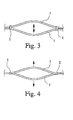
- FIGS. 3 and 4 how the connecting devices 2 act at different vibrations.
- Fig. 3 the two, connected to two connecting means 2 measuring tubes 1 are shown in a plan view, namely at the maximum deflection of an excitation oscillation, which takes place in the common plane of the measuring tubes 1.
- the connecting means 2 are claimed by the oscillating measuring tubes 1 so that it comes to bending vibrations of the connecting means 2 in the common plane of the measuring tubes 1.
- the stiffening plates 3 must also perform such bending vibrations in a corresponding plane. Such vibrations are opposed by the required upsetting of the stiffening plates 3 on the one hand and stretching on the opposite side, a very high bending resistance.
- the connecting means 2 can be relatively perpendicular to the vibrational excitation oscillations of vibrations of the measuring tubes 1 to torsional vibrations along the connecting line between the two measuring tubes 1 excite, as shown in Fig. 4. This frequency-wise good separation of these two types of vibration is achieved, which ultimately only a small influence the measurement signal is achieved by taking place perpendicular to the excitation vibrations oscillations of the measuring tubes.
- Fig. 5 is now with the relevant details and omitting sections of the measuring tubes 1 in the region of the connecting means 2 to better visualize the attachment of the measuring tubes 1 to the connecting device 2, a Coriolis mass flow meter according to a second preferred embodiment of the invention.
- the measuring tubes 1 are attached to the connecting device 2 not only in the holes 5, but also on the inner surfaces of the stiffening plates 3.
- welds 6 with the measuring tubes 1.
- Such an attachment is particularly advantageous in order to achieve a good frequency separation with longer measuring tubes 1, in particular if they have a small diameter.
- it is achieved namely, that the bending resistance, which the connecting device 2 opposite bending vibrations in the common plane of the measuring tubes 1, again significantly increased, while the torsional stiffness is hardly affected.
- a Coriolis mass flowmeter according to a third preferred embodiment of the invention can be seen.
- the connecting device 2 only consists of two stiffening plates 3, without these being connected to each other by means of a connecting plate 4.
- the stiffening plates 3, similar to the Coriolis mass flow meter according to the second preferred embodiment of the invention shown in FIG. 5, are welded to the measuring tubes 1 at their inner surfaces, as can be seen from the welds 6 shown in FIG.
- This construction is advantageous in that it is very inexpensive to produce and also easy to install.
- the principle of operation corresponds essentially to that of the apparent from Fig. 5 Coriolis mass flowmeter according to the second preferred embodiment of the invention, wherein only the action of the connecting plate 4 has been omitted, which, however, compared to the effect of the reinforcing plates 3 is substantially lower.
- connection means 2 for a Coriolis mass flowmeter according to a fourth preferred embodiment of the invention can be seen.
- This connecting device 2 shown there in section also has two stiffening plates 3 and a connecting plate 4 connecting them, wherein the connecting plate 4 is provided with holes 5 through which the measuring tubes 1 can be passed, so that the connecting device 2 are connected to the measuring tubes 1 can.
- the stiffening plates 3 are not arranged parallel to one another. Nevertheless, the effect is also achieved here that bends of the connecting device 2 in the common plane of the measuring tubes 1, a greater bending resistance is opposed, as torsional vibrations to the connecting line between the two measuring tubes. 1
Abstract
Description
Die Erfindung betrifft ein Massendurchflußmeßgerät, das nach dem Coriolis-Prinzip arbeitet, mit zwei wenigstens in einem Abschnitt in einer gemeinsamen Ebene verlaufenden Rohren und einer Verbindungseinrichtung, mittels derer die beiden Meßrohre in dem Abschnitt, in dem sie in der gemeinsamen Ebene verlaufen, miteinander verbunden sind.The invention relates to a mass flow meter, which operates on the Coriolis principle, with two at least in a section in a common plane extending tubes and a connecting means by means of which the two measuring tubes in the portion in which they extend in the common plane, connected to each other are.
Die vorliegende Erfindung betrifft also solche Coriolis-Massendurchflußmeßgeräte, die wenigstens zwei Meßrohre aufweisen, die im nichtschwingenden Zustand wenigstens abschnittsweise in einer gemeinsamen Ebene verlaufen, typischerweise nämlich parallel zueinander sind. Wesentlich bei solchen Coriolis-Massendurchflußmeßgeräten mit zwei oder mehr Meßrohren ist das Vorsehen wenigstens einer, gegebenenfalls auch zweier Verbindungseinrichtungen, wie oben beschrieben. Diese Verbindungseinrichtungen bestimmen die effektive Länge des Meßbereichs, da sie die Meßrohre fixieren und damit bei der Schwingungsanregung der Meßrohre jeweils einen Schwingungsknoten definieren. Solche Verbindungseinrichtungen werden daher auch als Schwingungsknotenplatten (Node-Plates) bezeichnet.The present invention thus relates to such Coriolis mass flowmeters, which have at least two measuring tubes, which extend in the non-oscillating state at least in sections in a common plane, namely namely parallel to each other. Essential in such Coriolis mass flowmeters with two or more measuring tubes is the provision of at least one, optionally also two connecting devices, as described above. These connecting devices determine the effective length of the measuring range, since they fix the measuring tubes and thus each define a vibration node in the vibrational excitation of the measuring tubes. Such connecting devices are therefore also referred to as nodal plates.
Während sich zwischen zwei solchen Schwingungsknotenplatten der eigentliche Meßbereich der Meßrohre befindet, stellen die einlaufseitigen bzw. auslaufseitigen Abschnitte der Meßrohre vor bzw. hinter den Schwingungsknotenplatten die jeweilige Verbindung zu dem Rohrleitungssystem her in das das Coriolis-Massendurchflußmeßgerät eingebaut ist. Dabei tragen diese einlauf- bzw. auslaufseitigen Abschnitte der Meßrohre auch zur Schwingungsisolierung des Coriolis-Massendurchflußmeßgeräts von dem Rohrleitungssystem bei.While the actual measuring range of the measuring tubes is located between two such node plates, the inlet side and outlet side portions of the measuring tubes in front of and behind the nodal plates make the respective connection to the piping in which the Coriolis mass flowmeter is installed. These inlet and outlet side portions of the measuring tubes also contribute to the vibration isolation of the Coriolis mass flowmeter from the piping system.
Neben der Bestimmung des effektiven Meßbereichs des Coriolis-Massendurchflußmeßgeräts dienen die Verbindungseinrichtungen auch dazu, die Anregungsschwingungen der Meßrohre, die innerhalb der gemeinsamen Ebene der Meßrohre erfolgen, von dazu orthogonalen Schwingungen frequenzmäßig zu trennen. Je größer der Frequenzabstand zwischen diesen beiden Schwingungen ist, um so weniger beeinflussen sich diese beiden Schwingungen untereinander, so daß es letztlich auch zu einer entsprechend geringen Beeinflussung des Meßsignals kommt, Diesbezüglich besteht bei aus der Praxis bekannten Coriolis-Massendurchflußmeßgeräten mit zwei oder mehr Meßrohren jedoch noch Verbesserungsbedarf, da die Beeinflussung der Anregungsschwingung durch dazu orthogonale Schwingungen der Meßrohre und damit letztlich auch die Störung des Meßsignals noch zu groß ist.In addition to the determination of the effective measuring range of the Coriolis mass flowmeter, the connecting devices also serve to frequency-separate the excitation vibrations of the measuring tubes, which take place within the common plane of the measuring tubes, from orthogonal oscillations. The greater the frequency separation between these two oscillations, the less these two oscillations influence each other, However, there is still room for improvement in Coriolis mass flowmeters known from practice with two or more measuring tubes, since the influencing of the excitation oscillation by orthogonal oscillations of the measuring tubes and thus ultimately also the disturbance the measuring signal is still too large.
Dementsprechend ist es die Aufgabe der Erfindung, ein derartiges Coriolis-Massendurchflußmeßgerät anzugeben, bei dem die Anregungsschwingungen der Meßrohre durch dazu orthogonale Schwingungen der Meßrohre möglichst wenig beeinflußt werden.Accordingly, it is the object of the invention to provide such a Coriolis mass flowmeter in which the excitation vibrations of the measuring tubes are influenced as little as possible by orthogonal oscillations of the measuring tubes.
Ausgehend von dem eingangs beschriebenen Coriolis-Massendurchflußmeßgerät ist die zuvor hergeleitete und aufgezeigte Aufgabe dadurch gelöst, daß die Verbindungseinrichtung derart ausgebildet und angeordnet ist, daß ihre Biegesteifigkeit für Biegungen in der gemeinsamen Ebene der Meßrohre größer ist als ihre Torsionssteifigkeit für Torsionsschwingungen um die Verbindungslinie zwischen den beiden Meßrohren.Starting from the above-described Coriolis mass flowmeter, the previously derived and indicated object is achieved in that the connecting device is designed and arranged so that their bending stiffness for bends in the common plane of the measuring tubes is greater than their torsional stiffness for torsional vibrations about the line connecting the between two measuring tubes.
Erfindungsgemäß ist also vorgesehen, daß die Biegesteifigkeit der Verbindungseinrichtung für Biegungen in der gemeinsamen Ebene der Meßrohre, in der im allgemeinen auch die Anregungsschwingungen der Meßrohre erfolgen, größer ist als die Torsionssteifigkeit der Verbindungseinrichtung für Torsionsschwingungen um eine derartige Achse, die die Verbindungsstellen der Verbindungseinrichtung mit den beiden Meßrohren miteinander verbindet. Da solche Torsionsschwingungen der Verbindungseinrichtung angeregt werden, wenn gegenphasige Schwingungen der Meßrohre senkrecht zu ihrer gemeinsamen Ebene angeregt werden, und Biegeschwingungen der Verbindungseinrichtung in der gemeinsamen Ebene der Meßrohre dann auftreten, wenn die Meßrohre in dieser Ebene zu Anregungsschwingungen angeregt werden, werden diese beide Arten von Schwingungen ― Anregungsschwingungen einerseits und Schwingungen senkrecht dazu andererseits - durch die Verbindungseinrichtung unterschiedlich beeinflußt. Während die Verbindungseinrichtung nämlich gegenphasigen Schwingungen senkrecht zur gemeinsamen Ebene der Meßrohr einen geringeren Biegewiderstand entgegensetzt, ist der Biegewiderstand für Schwingungen der Meßrohre in ihrer gemeinsamen Ebene, in der die Schwingungsanregung erfolgt, größer. Insgesamt wird damit frequenzmäßig eine gute Trennung von Anregungsschwingungen und dazu senkrechten Schwingungen der Meßrohre erzielt, wodurch im Ergebnis eine geringere Beeinflussung des Meßsignals durch die gegenseitige Beeinflussung von Anregungsschwingungen und Schwingungen senkrecht dazu erfolgt.According to the invention, it is thus provided that the bending stiffness of the connecting device for bends in the common plane of the measuring tubes, in which also the excitation vibrations of the measuring tubes are generally greater than the torsional stiffness of the connecting device for torsional vibrations about such an axis that the connection points of the connecting device with connects the two measuring tubes together. Since such torsional vibrations of the connecting means are excited when antiphase oscillations of the measuring tubes are excited perpendicular to their common plane, and bending vibrations of the connecting means in the common plane of the measuring tubes then occur when the measuring tubes are excited in this plane to excitation vibrations, these are both types of Vibrations - excitation vibrations on the one hand and vibrations perpendicular to the other - differently influenced by the connecting device. While the connecting device, namely opposite to the common plane of the measuring tube opposes a lower bending resistance to phase opposition, the bending resistance for vibrations of the measuring tubes in their common plane, in which the vibration excitation occurs, larger. Overall, a good separation of excitation vibrations and vertical oscillations of the measuring tubes is thus achieved in terms of frequency, as a result of which a smaller influence of the measuring signal takes place by the mutual influence of excitation oscillations and vibrations perpendicular thereto.
Grundsätzlich kann die Verbindungseinrichtung auf vielfältige Weisen ausgebildet sein, um zu erzielen, daß ihre Biegesteifigkeit für Biegungen in der gemeinsamen Ebene der Meßrohre größer ist als ihre Torsionssteifigkeit für Torsionsschwingungen um die Verbindungslinie zwischen den beiden Meßrohren. Gemäß einer bevorzugten Weiterbildung der Erfindung ist jedoch vorgesehen, daß die Verbindungseinrichtung zwei einander gegenüberliegende, jeweils an beiden Meßrohren befestigte Versteifungsplatten aufweist. Diese Versteifungsplatten können grundsätzlich gekrümmt sein, gemäß einer bevorzugten Weiterbildung der Erfindung sind sie jedoch eben ausgebildet.In principle, the connection means may be designed in a variety of ways to achieve that their bending stiffness for bends in the common plane of the measuring tubes is greater than their torsional stiffness for torsional vibrations about the connecting line between the two measuring tubes. According to a preferred embodiment of the invention, however, it is provided that the connecting device has two mutually opposite, in each case attached to two measuring tubes stiffening plates. These stiffening plates can be curved in principle, but according to a preferred embodiment of the invention, they are flat.
Diese Versteifungsplatten können im übrigen direkt oder/und mittelbar an den Meßrohren bzw. miteinander befestigt sein. Gemäß einer bevorzugten Weiterbildung der Erfindung ist dabei vorgesehen, daß die beiden Versteifungsplatten mittels einer Verbindungsplatte miteinander verbunden sind. Diese kann ebenfalls gekrümmt sein, bevorzugt ist sie jedoch auch eben ausgebildet.These stiffening plates can otherwise be directly or / and indirectly attached to the measuring tubes or with each other. According to a preferred embodiment of the invention, it is provided that the two stiffening plates are interconnected by means of a connecting plate. This may also be curved, but preferably it is also flat.
Grundsätzlich können die Versteifungsplatten unterschiedlich zueinander ausgerichtet sein. Gemäß einer bevorzugten Weiterbildung der Erfindung ist jedoch vorgesehen, daß die Versteifungsplatten parallel zueinander und vorzugsweise parallel zu der gemeinsamen Ebene der Meßrohre, ausgerichtet sind.In principle, the stiffening plates can be oriented differently from one another. According to a preferred embodiment of the invention, however, it is provided that the stiffening plates are aligned parallel to one another and preferably parallel to the common plane of the measuring tubes.
Es ist möglich, die Verbindungseinrichtung derart auszugestalten, daß die Versteifungsplatten und die Verbindungsplatte die gleichen Dicken aufweisen. Auf diese Weise läßt sich die Verbindungseinrichtung z. B. einfach aus einer gemeinsamen Platte herstellen, nämlich durch Umbiegen ihrer Seitenbereiche. Gemäß einer bevorzugten Weiterbildung der Erfindung ist jedoch vorgesehen, daß die Dicke der Verbindungsplatte größer ist als die Dicken der Versteifungsplatten. Auf diese Weise wird eine noch größere frequenzmäßige Trennung der Anregungsschwingungen von den dazu senkrechten Schwingungen der Meßrohre erzielt. Indem die Dicke der Versteifungsplatten nämlich geringer wird, wird die Torsionssteifigkeit für Torsionsschwingungen um die Verbindungslinie zwischen den beiden Meßrohren wesentlich stärker verringert als die Biegesteifigkeit für Biegungen in der gemeinsamen Ebene der Meßrohre. Insofern setzt eine Verbindungseinrichtung mit dünneren Versteifungsplatten den Anregungsschwingungen in der gemeinsamen Ebene der Meßrohre einen wesentlich höheren Biegewiderstand entgegen, als Schwingungen senkrecht dazu, die zu Torsionsschwingungen der Verbindungseinrichtung führen.It is possible to design the connecting device such that the stiffening plates and the connecting plate have the same thicknesses. In this way, the connection means z. B. simply from a common plate, namely by bending their side areas. According to a preferred embodiment of the invention, however, it is provided that the thickness of the connecting plate is greater than the thicknesses of the stiffening plates. In this way, an even greater frequency separation of the excitation vibrations from the vibrations perpendicular thereto achieved the measuring tubes. Namely, as the thickness of the reinforcing plates becomes smaller, the torsional rigidity for torsional vibrations around the connecting line between the two measuring tubes is reduced much more than the flexural rigidity for bends in the common plane of the measuring tubes. In this respect, a connecting device with thinner stiffening plates opposes the excitation vibrations in the common plane of the measuring tubes to a significantly higher bending resistance than vibrations perpendicular thereto, which lead to torsional vibrations of the connecting device.
Die Befestigung der Verbindungseinrichtung an den Meßrohren kann auf unterschiedliche Weisen vorgesehen sein. Insbesondere können die Versteifungsplatten, wie oben schon angedeutet, direkt oder mittelbar an den Meßrohren befestigt sein, nämlich z. B. über die Verbindungsplatte. Gemäß einer bevorzugten Weiterbildung der Erfindung ist dazu vorgesehen, daß die Verbindungsplatte für jedes Meßrohr eine Bohrung aufweist, durch die das jeweilige Meßrohr hindurchgeführt ist. Dabei ist gemäß einer bevorzugten Weiterbildung der Erfindung vorgesehen, daß der Innendurchmesser der Bohrung im wesentlichen dem Außendurchmesser der Meßrohre entspricht und die Meßrohre in den Bohrungen befestigt sind.The attachment of the connecting device to the measuring tubes can be provided in different ways. In particular, the stiffening plates, as already indicated above, be attached directly or indirectly to the measuring tubes, namely z. B. via the connection plate. According to a preferred embodiment of the invention it is provided that the connecting plate for each measuring tube has a bore through which the respective measuring tube is passed. It is provided according to a preferred embodiment of the invention that the inner diameter of the bore substantially corresponds to the outer diameter of the measuring tubes and the measuring tubes are mounted in the bores.
Für die Verbindungseinrichtung kommt eine Vielzahl von Materialien in Frage, wie verschiedene Metalle und Kunststoffmaterialien. Ebenso existiert für die Befestigung der Verbindungseinrichtung an den Meßrohren eine Vielzahl von Möglichkeiten, wie Verschweißen, Verlöten, Verkleben usw, insbesondere abhängig von den verwendeten Materialien.For the connecting means a variety of materials in question, such as various metals and plastic materials. Likewise, for the attachment of the connecting device to the measuring tubes a variety of ways, such as welding, soldering, gluing, etc., in particular depending on the materials used.
Im einzelnen gibt es nun eine Vielzahl von Möglichkeiten, das erfindungsgemäße Coriolis-Massendurchflußmeßgerät auszugestalten und weiterzubilden. Dazu wird auf die dem Patentanspruch 1 nachgeordneten Patentansprüche sowie auf die nachfolgende detaillierte Beschreibung bevorzugter Ausführungsbeispiele der Erfindung unter Bezugnahme auf die Zeichnung verwiesen.In particular, there are a variety of ways to design and develop the Coriolis mass flowmeter according to the invention. For this purpose, reference is made to the claims subordinate to claim 1 and to the following detailed description of preferred embodiments of the invention with reference to the drawings.
In der Zeichnung zeigt
- Fig. 1
- eine Verbindungseinrichtung für ein Coriolis-Massendurchflußmeßgerät gemäß einem ersten bevorzugten Ausführungsbeispiel der Erfindung in perspektivischer Ansicht,
- Fig. 2
- Meßrohre und Verbindungseinrichtungen eines Coriolis-Massendurchflußmeßgeräts gemäß dem ersten bevorzugten Ausführungsbeispiel der Erfindung in perspektivischer Ansicht,
- Fig. 3
- eine Schwingungsanregung der Meßrohre des Coriolis-Massendurchflußmeßgeräts gemäß dem ersten bevorzugten Ausführungsbeispiel der Erfindung in Draufsicht,
- Fig. 4
- Schwingungen der Meßrohre des Coriolis-Massendurchflußmeßgeräts gemäß dem ersten bevorzugten Ausführungsbeispiel der Erfindung senkrecht zur Ebene der Schwingungsanregung in einer Seitenansicht,
- Fig, 5
- ausschnittsweise Meßrohre und eine Verbindungseinrichtung eines Coriolis-Maßßendurchflußmeßgcräts gemäß einem zweiten bevorzugten Ausführungsbeispiel der Erfindung,
- Fig. 6
- ausschnittsweise Meßrohre und eine Verbindungseinrichtung eines Coriolis-Massendurchflußmeßgeräts gemäß einem dritten bevorzugten Ausführungsbeispiel der Erfindung und
- Fig. 7
- eine Verbindungseinrichtung für ein Coriolis-Massendurchflußmeßgerät gemäß einem vierten bevorzugten Ausführungsbeispiel der Erfindung im Schnitt.
- Fig. 1
- a connection device for a Coriolis mass flowmeter according to a first preferred embodiment of the invention in perspective view,
- Fig. 2
- Measuring tubes and connecting devices of a Coriolis mass flowmeter according to the first preferred embodiment of the invention in perspective view,
- Fig. 3
- a vibration excitation of the measuring tubes of the Coriolis mass flowmeter according to the first preferred embodiment of the invention in plan view,
- Fig. 4
- Vibrations of the measuring tubes of the Coriolis mass flowmeter according to the first preferred embodiment of the invention perpendicular to the plane of the vibration excitation in a side view,
- Fig. 5
- sectional measuring tubes and a connecting device of a Coriolis Maßßendurchflußmeßgcräts according to a second preferred embodiment of the invention,
- Fig. 6
- sectional measuring tubes and a connecting device of a Coriolis mass flowmeter according to a third preferred embodiment of the invention and
- Fig. 7
- a connection device for a Coriolis mass flowmeter according to a fourth preferred embodiment of the invention in section.
Aus den Fig. 1 und 2 ist mit den vorliegend relevanten Details ein Coriolis-Massendurchflußmeßgerät gemäß einem ersten bevorzugten Ausführungsbeispiel der Erfindung ersichtlich. Zu erkennen sind zwei gerade, parallel zueinander verlaufende Meßrohre 1, die mit zwei Verbindungseinrichtungen 2 versehen sind. Die Verbindungseinrichtungen 2 weisen im Querschnitt jeweils im wesentlichen ein U-Profil auf, wobei zwei Versteifungsplatten 3 derart mittels einer Verbindungsplatte 4 miteinander verbunden sind, daß die Versteifungsplatten 3 parallel zueinander und jeweils senkrecht zur Verbindungsplatte 4 ausgerichtet sind. Die Dicke der Versteifungsplatten 3 ist geringer als die Dikke der Verbindungsplatte 4, wodurch der schon oben angesprochene Effekt erzielt wird, daß der Biegewiderstand der Verbindungseinrichtungen 2 für Torsionsschwingungen deutlich geringer ist als für Biegeschwingungen in der gemeinsamen Ebene der Meßrohre 1.1 and 2 with the presently relevant details a Coriolis mass flowmeter according to a first preferred embodiment of the invention can be seen. Evident are two straight, parallel to each
In der Verbindungsplatte 4 sind zwei Bohrungen 5 vorgesehen, deren Innendurchmesser im wesentlichen dem Außendurchmesser der Meßrohre 1 entspricht. Auf diese Weise können die Verbindungseinrichtungen 2 auf die Meßrohre 1 aufgeschoben und dann mit diesen verbunden werden. Gemäß dem ersten bevorzugten Ausführungsbeispiel der Erfindung ist vorgesehen, daß die Verbindungseinrichtungen 2 aus Edelstahl hergestellt sind, so daß sie mit den Meßrohren 1 aus Titan verschweißt werden können.In the connecting
Aus den Fig. 3 und 4 ist nun ersichtlich, wie die Verbindungseinrichtungen 2 bei verschiedenen Schwingungen wirken. In Fig. 3 sind die beiden, mit zwei Verbindungseinrichtungen 2 verbundenen Meßrohre 1 in einer Draufsicht dargestellt, und zwar bei der maximalen Auslenkung einer Anregungsschwingung, die in der gemeinsamen Ebene der Meßrohre 1 erfolgt. Es ist erkennbar, daß bei solchen Anregungsschwingungen die Verbindungseinrichtungen 2 durch die schwingenden Meßrohre 1 derart beansprucht werden, daß es zu Biegeschwingungen der Verbindungseinrichtungen 2 in der gemeinsamen Ebene der Meßrohre 1 kommt. Dazu müssen die Versteifungsplatten 3 ebenfalls solche Biegeschwingungen in einer entsprechenden Ebene ausführen. Solchen Schwingungen wird durch das dafür erforderliche Stauchen der Versteifungsplatten 3 auf der einen Seite bzw. Dehnen auf der gegenüberliegenden Seite ein sehr hoher Biegewiderstand entgegengesetzt.It can now be seen from FIGS. 3 and 4 how the connecting
Im Gegensatz dazu lassen sich die Verbindungseinrichtungen 2 bei gegenphasigen Schwingungen der Meßrohre 1 senkrecht zur Ebene der Schwingungsanregungen verhältnismäßig leicht zu Torsionsschwingungen längs der Verbindungslinie zwischen den beiden Meßrohren 1 anregen, wie aus Fig. 4 ersichtlich. Damit wird eine frequenzmäßig gute Trennung dieser beiden Schwingungsarten erzielt, wodurch letztlich eine nur geringe Beeinflussung des Meßsignals durch senkrecht zu den Anregungsschwingungen erfolgende Schwingungen der Meßrohre erzielt wird.In contrast, the connecting
Aus Fig. 5 ist nun mit den relevanten Details und unter Weglassung von Abschnitten der Meßrohre 1 im Bereich der Verbindungseinrichtungen 2 zur besseren Sichtbarmachung der Befestigung der Meßrohre 1 an der Verbindungseinrichtung 2 ein Coriolis-Massendurchflußmeßgerät gemäß einem zweiten bevorzugten Ausführungsbeispiel der Erfindung ersichtlich. Dabei ist vorgesehen, daß die Meßrohre 1 an der Verbindungseinrichtung 2 nicht nur in den Bohrungen 5 befestigt sind, sondern auch an den Innenflächen der Versteifungsplatten 3. Wie aus Fig. 5 ersichtlich, sind dort ebenfalls Verschweißungen 6 mit den Meßrohren 1 vorgesehen. Eine derartige Befestigung ist insbesondere vorteilhaft, um eine gute Frequenztrennung bei längeren Meßrohren 1 zu erzielen, insbesondere wenn diese einen geringen Durchmesser aufweisen. Bei dieser Konstruktion wird nämlich erreicht, daß der Biegewiderstand, den die Verbindungseinrichtung 2 Biegeschwingungen in der gemeinsamen Ebene der Meßrohre 1 entgegengesetzt, nochmals deutlich erhöht wird, während die Torsionssteifigkeit kaum beeinflußt wird.From Fig. 5 is now with the relevant details and omitting sections of the measuring
Aus Fig. 6 ist, entsprechend Fig. 5 mit allen relevanten Details und unter Weglassung der Abschnitte der Meßrohre 1 im Bereich der Befestigung an der Verbindungseinrichtung 2, ein Coriolis-Massendurchflußmeßgerät gemäß einem dritten bevorzugten Ausführungsbeispiel der Erfindung ersichtlich. Dabei besteht die Verbindungseinrichtung 2 nur aus zwei Versteifungsplatten 3, ohne daß diese mittels einer Verbindungsplatte 4 miteinander verbunden sind. Die Versteifungsplatten 3 sind, ähnlich wie bei dem Coriolis-Massendurchflußmeßgerät gemäß dem aus Fig. 5 ersichtlichen zweiten bevorzugten Ausführungsbeispiel der Erfindung, an ihren Innenflächen mit den Meßrohren 1 verschweißt, wie anhand der in Fig. 6 gezeigten Verschweißungen 6 ersichtlich. Diese Konstruktion ist insofern vorteilhaft, als daß sie sehr kostengünstig herstellbar und darüber hinaus leicht montierbar ist. Das Funktionsprinzip entspricht im wesentlichen dem des aus Fig. 5 ersichtlichen Coriolis-Massendurchflußmeßgeräts gemäß dem zweiten bevorzugten Ausführungsbeispiel der Erfindung, wobei lediglich auf die Wirkung der Verbindungsplatte 4 verzichtet worden ist, die jedoch im Vergleich mit der Wirkung der Versteifungsplatten 3 wesentlich geringer ist.From Fig. 6, corresponding to Fig. 5 with all relevant details and omitting the portions of the measuring
Aus Fig. 7 ist schließlich eine Verbindungseinrichtung 2 für ein Coriolis-Massendurchflußmeßgerät gemäß einem vierten bevorzugten Ausführungsbeispiel der Erfindung ersichtlich. Diese dort im Schnitt dargestellte Verbindungseinrichtung 2 weist ebenfalls zwei Versteifungsplatten 3 und eine diese verbindende Verbindungsplatte 4 auf, wobei die Verbindungsplatte 4 mit Bohrungen 5 versehen ist, durch die die Meßrohre 1 hindurchgeführt werden können, so daß die Verbindungseinrichtung 2 mit den Meßrohren 1 verbunden werden kann. Allerdings sind vorliegend die Versteifungsplatten 3 nicht parallel zueinander angeordnet. Gleichwohl wird auch hier der Effekt erzielt, daß Biegungen der Verbindungseinrichtung 2 in der gemeinsamen Ebene der Meßrohre 1 ein größerer Biegewiderstand entgegengesetzt wird, als Torsionsschwingungen, um die Verbindungslinie zwischen den beiden Meßrohren 1.From Fig. 7, finally, a connection means 2 for a Coriolis mass flowmeter according to a fourth preferred embodiment of the invention can be seen. This connecting
Claims (8)
Applications Claiming Priority (1)
| Application Number | Priority Date | Filing Date | Title |
|---|---|---|---|
| DE102005003161A DE102005003161B4 (en) | 2005-01-21 | 2005-01-21 | The mass flow meter |
Publications (2)
| Publication Number | Publication Date |
|---|---|
| EP1684055A1 true EP1684055A1 (en) | 2006-07-26 |
| EP1684055B1 EP1684055B1 (en) | 2011-04-13 |
Family
ID=36218355
Family Applications (1)
| Application Number | Title | Priority Date | Filing Date |
|---|---|---|---|
| EP05022876A Active EP1684055B1 (en) | 2005-01-21 | 2005-10-20 | Coriolis mass flow meter |
Country Status (6)
| Country | Link |
|---|---|
| US (1) | US7275449B2 (en) |
| EP (1) | EP1684055B1 (en) |
| JP (1) | JP4695988B2 (en) |
| AT (1) | ATE505714T1 (en) |
| DE (2) | DE102005003161B4 (en) |
| DK (1) | DK1684055T3 (en) |
Cited By (2)
| Publication number | Priority date | Publication date | Assignee | Title |
|---|---|---|---|---|
| WO2008059015A1 (en) * | 2006-11-15 | 2008-05-22 | Siemens Aktiengesellschaft | Mass flow measuring device |
| WO2014109747A1 (en) * | 2013-01-10 | 2014-07-17 | Micro Motion, Inc. | Method and apparatus for a vibratory meter |
Families Citing this family (11)
| Publication number | Priority date | Publication date | Assignee | Title |
|---|---|---|---|---|
| DE102006034274B4 (en) * | 2006-07-21 | 2012-06-28 | Krohne Ag | The mass flow meter |
| US7784359B2 (en) * | 2008-04-17 | 2010-08-31 | Rosemount Aerospace Inc. | Coriolis effect mass flow meter and gyroscope |
| DE102008035877A1 (en) * | 2008-08-01 | 2010-02-04 | Endress + Hauser Flowtec Ag | Vibration-type transducers |
| JP5674675B2 (en) * | 2008-11-19 | 2015-02-25 | マイクロ モーション インコーポレイテッド | Coriolis flowmeter with improved vibration mode separation |
| RU2464534C1 (en) * | 2008-11-19 | 2012-10-20 | Майкро Моушн, Инк. | Flow metre (versions) and method of increasing separation interval between two or more vibrational frequencies of vibratory flow metre |
| EP4016013A1 (en) | 2012-10-11 | 2022-06-22 | Endress + Hauser Flowtec AG | Measuring system for determining a volume flow and / or a volume flow rate of a medium flowing in a pipeline |
| DE102012109729A1 (en) | 2012-10-12 | 2014-05-15 | Endress + Hauser Flowtec Ag | Measuring system for determining volumetric flow during measuring interval of total flowed volume of flowing medium, particularly liquid or gas, has vibration element for guiding flowing portion of medium, where vibration element has lumen |
| CN105358944B (en) | 2013-04-18 | 2019-05-14 | 高准公司 | Self aligned strut |
| EP3676575A1 (en) * | 2017-08-29 | 2020-07-08 | Micro Motion, Inc. | Integrated brace bar |
| DE102018005197B3 (en) * | 2018-06-29 | 2019-11-14 | Rota Yokogawa Gmbh & Co. Kg | Coriolis mass flow and density meter with reduced pressure dependence |
| DE102019129744A1 (en) * | 2019-11-05 | 2021-05-06 | Krohne Ag | Coriolis mass flow meter and node element |
Citations (2)
| Publication number | Priority date | Publication date | Assignee | Title |
|---|---|---|---|---|
| US5602345A (en) * | 1994-05-26 | 1997-02-11 | Endress + Hauser Flowtec Ag | Double straight tube coriolis type mass flow sensor |
| EP1279935A2 (en) * | 2001-07-23 | 2003-01-29 | FMC Technologies, Inc. | Method for decoupling extraneous modes of vibration in a Coriolis mass flowmeter |
Family Cites Families (13)
| Publication number | Priority date | Publication date | Assignee | Title |
|---|---|---|---|---|
| US4823614A (en) * | 1986-04-28 | 1989-04-25 | Dahlin Erik B | Coriolis-type mass flowmeter |
| US4781069A (en) * | 1986-06-05 | 1988-11-01 | Exac Corporation | Mode selection apparatus for multiple tube coriolis type mass flow meters |
| EP0431132B1 (en) * | 1989-06-09 | 1998-09-16 | Micro Motion Incorporated | Improved stability coriolis mass flow meter |
| JPH0499919A (en) * | 1990-08-20 | 1992-03-31 | Tokico Ltd | Mass flowmeter |
| US5226330A (en) * | 1991-10-31 | 1993-07-13 | Lew Hyok S | High sensitivity mass flowmeter |
| DE59201347D1 (en) * | 1992-11-06 | 1995-03-16 | Flowtec Ag | Coriolis mass flow meter. |
| US5370002A (en) * | 1993-07-23 | 1994-12-06 | Micro Motion, Inc. | Apparatus and method for reducing stress in the brace bar of a Coriolis effect mass flow meter |
| JPH08271311A (en) * | 1995-03-31 | 1996-10-18 | Tokico Ltd | Vibration type measuring device |
| JP2000046615A (en) * | 1998-07-30 | 2000-02-18 | Yokogawa Electric Corp | Coriolis mass flowmeter |
| US6308580B1 (en) * | 1999-03-19 | 2001-10-30 | Micro Motion, Inc. | Coriolis flowmeter having a reduced flag dimension |
| JP2002340648A (en) * | 2001-05-16 | 2002-11-27 | Oval Corp | Structure for fixing vibration tube and support plate or member by brazing in coriolis-type mass flowmeter |
| US6920798B2 (en) * | 2001-09-21 | 2005-07-26 | Endress + Hauser Flowtec Ag | Vibratory transducer |
| EP1296119A1 (en) * | 2001-09-21 | 2003-03-26 | Endress + Hauser Flowtec AG | Vibration type measuring sensor |
-
2005
- 2005-01-21 DE DE102005003161A patent/DE102005003161B4/en active Active
- 2005-10-20 EP EP05022876A patent/EP1684055B1/en active Active
- 2005-10-20 DK DK05022876.6T patent/DK1684055T3/en active
- 2005-10-20 AT AT05022876T patent/ATE505714T1/en active
- 2005-10-20 DE DE502005011238T patent/DE502005011238D1/en active Active
- 2005-12-12 US US11/299,612 patent/US7275449B2/en active Active
-
2006
- 2006-01-18 JP JP2006009457A patent/JP4695988B2/en active Active
Patent Citations (2)
| Publication number | Priority date | Publication date | Assignee | Title |
|---|---|---|---|---|
| US5602345A (en) * | 1994-05-26 | 1997-02-11 | Endress + Hauser Flowtec Ag | Double straight tube coriolis type mass flow sensor |
| EP1279935A2 (en) * | 2001-07-23 | 2003-01-29 | FMC Technologies, Inc. | Method for decoupling extraneous modes of vibration in a Coriolis mass flowmeter |
Cited By (6)
| Publication number | Priority date | Publication date | Assignee | Title |
|---|---|---|---|---|
| WO2008059015A1 (en) * | 2006-11-15 | 2008-05-22 | Siemens Aktiengesellschaft | Mass flow measuring device |
| WO2014109747A1 (en) * | 2013-01-10 | 2014-07-17 | Micro Motion, Inc. | Method and apparatus for a vibratory meter |
| CN105026898A (en) * | 2013-01-10 | 2015-11-04 | 高准公司 | Method and apparatus for a vibratory meter |
| RU2608340C1 (en) * | 2013-01-10 | 2017-01-17 | Майкро Моушн, Инк. | Method and device for vibrational meter |
| US9696194B2 (en) | 2013-01-10 | 2017-07-04 | Micro Motion, Inc. | Method and apparatus for a vibratory meter |
| CN105026898B (en) * | 2013-01-10 | 2018-02-06 | 高准公司 | Method and apparatus for vibration gauge |
Also Published As
| Publication number | Publication date |
|---|---|
| EP1684055B1 (en) | 2011-04-13 |
| DK1684055T3 (en) | 2011-07-25 |
| JP2006201170A (en) | 2006-08-03 |
| DE502005011238D1 (en) | 2011-05-26 |
| DE102005003161A1 (en) | 2006-07-27 |
| JP4695988B2 (en) | 2011-06-08 |
| ATE505714T1 (en) | 2011-04-15 |
| US20060162468A1 (en) | 2006-07-27 |
| DE102005003161B4 (en) | 2007-03-01 |
| US7275449B2 (en) | 2007-10-02 |
Similar Documents
| Publication | Publication Date | Title |
|---|---|---|
| EP1684055B1 (en) | Coriolis mass flow meter | |
| EP1798532B1 (en) | Coriolis mass flow meter | |
| EP1528374B1 (en) | Coriolis mass flowmeter | |
| EP1881303B1 (en) | Coriolis Mass flow measuring device | |
| DE19621365C2 (en) | Mass flow meter | |
| EP0473919B1 (en) | Device for measurement and dosage of mass flows | |
| EP1936333B1 (en) | Ultrasound flow measuring device | |
| EP2625492B1 (en) | Coriolis mass flow meter | |
| EP2600122B1 (en) | Coriolis mass flow measuring device | |
| WO2008059015A1 (en) | Mass flow measuring device | |
| DE102012016490A1 (en) | Coriolis mass flowmeter | |
| DE102010030341A1 (en) | Coriolis mass flow meter | |
| EP2310812B1 (en) | Vibration-type measuring sensor | |
| WO2009050133A1 (en) | Mass flow meter and method for producing a reinforcement frame for a mass flow meter | |
| EP3559608A1 (en) | Vibration-type sensor for measuring the density and/or mass flow rate of a medium | |
| EP2559977B1 (en) | Coriolis mass flow measuring device | |
| EP3631378B1 (en) | Sensor for measuring the mass flow of a flowable medium | |
| EP3559607B1 (en) | Vibratory type meter for measuring the density and/or flow rate of a flowing medium | |
| EP3663728A1 (en) | Measuring device for detecting a fluid quantity | |
| DE4016907C2 (en) | ||
| DE10351312B4 (en) | Attachment and Coriolis mass flow meter with this attachment | |
| EP1421349B1 (en) | Vibration-type flow sensor | |
| EP4302066A1 (en) | Modular measuring device for determining the density of a measurement medium | |
| DE102018001778A1 (en) | Mass flow and density meters according to the Coriolis principle with low pressure dependence and method of manufacture | |
| EP1672331A1 (en) | Coriolis mass flow measuring device |
Legal Events
| Date | Code | Title | Description |
|---|---|---|---|
| PUAI | Public reference made under article 153(3) epc to a published international application that has entered the european phase |
Free format text: ORIGINAL CODE: 0009012 |
|
| AK | Designated contracting states |
Kind code of ref document: A1 Designated state(s): AT BE BG CH CY CZ DE DK EE ES FI FR GB GR HU IE IS IT LI LT LU LV MC NL PL PT RO SE SI SK TR |
|
| AX | Request for extension of the european patent |
Extension state: AL BA HR MK YU |
|
| 17P | Request for examination filed |
Effective date: 20061017 |
|
| 17Q | First examination report despatched |
Effective date: 20061115 |
|
| AKX | Designation fees paid |
Designated state(s): AT BE BG CH CY CZ DE DK EE ES FI FR GB GR HU IE IS IT LI LT LU LV MC NL PL PT RO SE SI SK TR |
|
| GRAP | Despatch of communication of intention to grant a patent |
Free format text: ORIGINAL CODE: EPIDOSNIGR1 |
|
| GRAS | Grant fee paid |
Free format text: ORIGINAL CODE: EPIDOSNIGR3 |
|
| GRAA | (expected) grant |
Free format text: ORIGINAL CODE: 0009210 |
|
| AK | Designated contracting states |
Kind code of ref document: B1 Designated state(s): AT BE BG CH CY CZ DE DK EE ES FI FR GB GR HU IE IS IT LI LT LU LV MC NL PL PT RO SE SI SK TR |
|
| REG | Reference to a national code |
Ref country code: GB Ref legal event code: FG4D Free format text: NOT ENGLISH |
|
| REG | Reference to a national code |
Ref country code: CH Ref legal event code: EP |
|
| REG | Reference to a national code |
Ref country code: IE Ref legal event code: FG4D Free format text: LANGUAGE OF EP DOCUMENT: GERMAN |
|
| REF | Corresponds to: |
Ref document number: 502005011238 Country of ref document: DE Date of ref document: 20110526 Kind code of ref document: P |
|
| REG | Reference to a national code |
Ref country code: DE Ref legal event code: R096 Ref document number: 502005011238 Country of ref document: DE Effective date: 20110526 |
|
| REG | Reference to a national code |
Ref country code: DK Ref legal event code: T3 |
|
| REG | Reference to a national code |
Ref country code: NL Ref legal event code: VDEP Effective date: 20110413 |
|
| LTIE | Lt: invalidation of european patent or patent extension |
Effective date: 20110413 |
|
| PG25 | Lapsed in a contracting state [announced via postgrant information from national office to epo] |
Ref country code: PT Free format text: LAPSE BECAUSE OF FAILURE TO SUBMIT A TRANSLATION OF THE DESCRIPTION OR TO PAY THE FEE WITHIN THE PRESCRIBED TIME-LIMIT Effective date: 20110816 Ref country code: SE Free format text: LAPSE BECAUSE OF FAILURE TO SUBMIT A TRANSLATION OF THE DESCRIPTION OR TO PAY THE FEE WITHIN THE PRESCRIBED TIME-LIMIT Effective date: 20110413 Ref country code: LT Free format text: LAPSE BECAUSE OF FAILURE TO SUBMIT A TRANSLATION OF THE DESCRIPTION OR TO PAY THE FEE WITHIN THE PRESCRIBED TIME-LIMIT Effective date: 20110413 |
|
| REG | Reference to a national code |
Ref country code: IE Ref legal event code: FD4D |
|
| PG25 | Lapsed in a contracting state [announced via postgrant information from national office to epo] |
Ref country code: LV Free format text: LAPSE BECAUSE OF FAILURE TO SUBMIT A TRANSLATION OF THE DESCRIPTION OR TO PAY THE FEE WITHIN THE PRESCRIBED TIME-LIMIT Effective date: 20110413 Ref country code: GR Free format text: LAPSE BECAUSE OF FAILURE TO SUBMIT A TRANSLATION OF THE DESCRIPTION OR TO PAY THE FEE WITHIN THE PRESCRIBED TIME-LIMIT Effective date: 20110714 Ref country code: SI Free format text: LAPSE BECAUSE OF FAILURE TO SUBMIT A TRANSLATION OF THE DESCRIPTION OR TO PAY THE FEE WITHIN THE PRESCRIBED TIME-LIMIT Effective date: 20110413 Ref country code: CY Free format text: LAPSE BECAUSE OF FAILURE TO SUBMIT A TRANSLATION OF THE DESCRIPTION OR TO PAY THE FEE WITHIN THE PRESCRIBED TIME-LIMIT Effective date: 20110413 Ref country code: IS Free format text: LAPSE BECAUSE OF FAILURE TO SUBMIT A TRANSLATION OF THE DESCRIPTION OR TO PAY THE FEE WITHIN THE PRESCRIBED TIME-LIMIT Effective date: 20110813 Ref country code: ES Free format text: LAPSE BECAUSE OF FAILURE TO SUBMIT A TRANSLATION OF THE DESCRIPTION OR TO PAY THE FEE WITHIN THE PRESCRIBED TIME-LIMIT Effective date: 20110724 Ref country code: FI Free format text: LAPSE BECAUSE OF FAILURE TO SUBMIT A TRANSLATION OF THE DESCRIPTION OR TO PAY THE FEE WITHIN THE PRESCRIBED TIME-LIMIT Effective date: 20110413 |
|
| PG25 | Lapsed in a contracting state [announced via postgrant information from national office to epo] |
Ref country code: NL Free format text: LAPSE BECAUSE OF FAILURE TO SUBMIT A TRANSLATION OF THE DESCRIPTION OR TO PAY THE FEE WITHIN THE PRESCRIBED TIME-LIMIT Effective date: 20110413 |
|
| PG25 | Lapsed in a contracting state [announced via postgrant information from national office to epo] |
Ref country code: IE Free format text: LAPSE BECAUSE OF FAILURE TO SUBMIT A TRANSLATION OF THE DESCRIPTION OR TO PAY THE FEE WITHIN THE PRESCRIBED TIME-LIMIT Effective date: 20110413 Ref country code: CZ Free format text: LAPSE BECAUSE OF FAILURE TO SUBMIT A TRANSLATION OF THE DESCRIPTION OR TO PAY THE FEE WITHIN THE PRESCRIBED TIME-LIMIT Effective date: 20110413 Ref country code: EE Free format text: LAPSE BECAUSE OF FAILURE TO SUBMIT A TRANSLATION OF THE DESCRIPTION OR TO PAY THE FEE WITHIN THE PRESCRIBED TIME-LIMIT Effective date: 20110413 |
|
| PLBE | No opposition filed within time limit |
Free format text: ORIGINAL CODE: 0009261 |
|
| STAA | Information on the status of an ep patent application or granted ep patent |
Free format text: STATUS: NO OPPOSITION FILED WITHIN TIME LIMIT |
|
| PG25 | Lapsed in a contracting state [announced via postgrant information from national office to epo] |
Ref country code: RO Free format text: LAPSE BECAUSE OF FAILURE TO SUBMIT A TRANSLATION OF THE DESCRIPTION OR TO PAY THE FEE WITHIN THE PRESCRIBED TIME-LIMIT Effective date: 20110413 Ref country code: PL Free format text: LAPSE BECAUSE OF FAILURE TO SUBMIT A TRANSLATION OF THE DESCRIPTION OR TO PAY THE FEE WITHIN THE PRESCRIBED TIME-LIMIT Effective date: 20110413 Ref country code: SK Free format text: LAPSE BECAUSE OF FAILURE TO SUBMIT A TRANSLATION OF THE DESCRIPTION OR TO PAY THE FEE WITHIN THE PRESCRIBED TIME-LIMIT Effective date: 20110413 |
|
| 26N | No opposition filed |
Effective date: 20120116 |
|
| BERE | Be: lapsed |
Owner name: KROHNE A.G. Effective date: 20111031 |
|
| REG | Reference to a national code |
Ref country code: DE Ref legal event code: R097 Ref document number: 502005011238 Country of ref document: DE Effective date: 20120116 |
|
| PG25 | Lapsed in a contracting state [announced via postgrant information from national office to epo] |
Ref country code: MC Free format text: LAPSE BECAUSE OF NON-PAYMENT OF DUE FEES Effective date: 20111031 Ref country code: IT Free format text: LAPSE BECAUSE OF FAILURE TO SUBMIT A TRANSLATION OF THE DESCRIPTION OR TO PAY THE FEE WITHIN THE PRESCRIBED TIME-LIMIT Effective date: 20110413 |
|
| PG25 | Lapsed in a contracting state [announced via postgrant information from national office to epo] |
Ref country code: BE Free format text: LAPSE BECAUSE OF NON-PAYMENT OF DUE FEES Effective date: 20111031 |
|
| REG | Reference to a national code |
Ref country code: AT Ref legal event code: MM01 Ref document number: 505714 Country of ref document: AT Kind code of ref document: T Effective date: 20111020 |
|
| PG25 | Lapsed in a contracting state [announced via postgrant information from national office to epo] |
Ref country code: AT Free format text: LAPSE BECAUSE OF NON-PAYMENT OF DUE FEES Effective date: 20111020 |
|
| PG25 | Lapsed in a contracting state [announced via postgrant information from national office to epo] |
Ref country code: LU Free format text: LAPSE BECAUSE OF NON-PAYMENT OF DUE FEES Effective date: 20111020 |
|
| PG25 | Lapsed in a contracting state [announced via postgrant information from national office to epo] |
Ref country code: BG Free format text: LAPSE BECAUSE OF FAILURE TO SUBMIT A TRANSLATION OF THE DESCRIPTION OR TO PAY THE FEE WITHIN THE PRESCRIBED TIME-LIMIT Effective date: 20110713 |
|
| PG25 | Lapsed in a contracting state [announced via postgrant information from national office to epo] |
Ref country code: DE Free format text: LAPSE BECAUSE OF NON-PAYMENT OF DUE FEES Effective date: 20130501 |
|
| REG | Reference to a national code |
Ref country code: DE Ref legal event code: R119 Ref document number: 502005011238 Country of ref document: DE Effective date: 20130501 |
|
| PG25 | Lapsed in a contracting state [announced via postgrant information from national office to epo] |
Ref country code: TR Free format text: LAPSE BECAUSE OF FAILURE TO SUBMIT A TRANSLATION OF THE DESCRIPTION OR TO PAY THE FEE WITHIN THE PRESCRIBED TIME-LIMIT Effective date: 20110413 |
|
| PG25 | Lapsed in a contracting state [announced via postgrant information from national office to epo] |
Ref country code: HU Free format text: LAPSE BECAUSE OF FAILURE TO SUBMIT A TRANSLATION OF THE DESCRIPTION OR TO PAY THE FEE WITHIN THE PRESCRIBED TIME-LIMIT Effective date: 20110413 |
|
| REG | Reference to a national code |
Ref country code: FR Ref legal event code: PLFP Year of fee payment: 11 |
|
| REG | Reference to a national code |
Ref country code: FR Ref legal event code: PLFP Year of fee payment: 12 |
|
| REG | Reference to a national code |
Ref country code: FR Ref legal event code: PLFP Year of fee payment: 13 |
|
| REG | Reference to a national code |
Ref country code: FR Ref legal event code: PLFP Year of fee payment: 14 |
|
| P01 | Opt-out of the competence of the unified patent court (upc) registered |
Effective date: 20230607 |
|
| PGFP | Annual fee paid to national office [announced via postgrant information from national office to epo] |
Ref country code: GB Payment date: 20231020 Year of fee payment: 19 |
|
| PGFP | Annual fee paid to national office [announced via postgrant information from national office to epo] |
Ref country code: FR Payment date: 20231023 Year of fee payment: 19 Ref country code: DK Payment date: 20231024 Year of fee payment: 19 Ref country code: CH Payment date: 20231102 Year of fee payment: 19 |