EP1683984A1 - Brake for vehicle wheels provided with constraining elements of the elastically operating braking band - Google Patents
Brake for vehicle wheels provided with constraining elements of the elastically operating braking band Download PDFInfo
- Publication number
- EP1683984A1 EP1683984A1 EP06001085A EP06001085A EP1683984A1 EP 1683984 A1 EP1683984 A1 EP 1683984A1 EP 06001085 A EP06001085 A EP 06001085A EP 06001085 A EP06001085 A EP 06001085A EP 1683984 A1 EP1683984 A1 EP 1683984A1
- Authority
- EP
- European Patent Office
- Prior art keywords
- pawl
- brake
- brake according
- seat
- band
- Prior art date
- Legal status (The legal status is an assumption and is not a legal conclusion. Google has not performed a legal analysis and makes no representation as to the accuracy of the status listed.)
- Granted
Links
- 239000007769 metal material Substances 0.000 claims description 2
- 230000000284 resting effect Effects 0.000 claims 1
- 230000035882 stress Effects 0.000 description 4
- 238000000034 method Methods 0.000 description 2
- 230000008646 thermal stress Effects 0.000 description 2
- 230000007774 longterm Effects 0.000 description 1
- 230000036316 preload Effects 0.000 description 1
- 238000005096 rolling process Methods 0.000 description 1
Images

Classifications
-
- F—MECHANICAL ENGINEERING; LIGHTING; HEATING; WEAPONS; BLASTING
- F16—ENGINEERING ELEMENTS AND UNITS; GENERAL MEASURES FOR PRODUCING AND MAINTAINING EFFECTIVE FUNCTIONING OF MACHINES OR INSTALLATIONS; THERMAL INSULATION IN GENERAL
- F16D—COUPLINGS FOR TRANSMITTING ROTATION; CLUTCHES; BRAKES
- F16D65/00—Parts or details
- F16D65/02—Braking members; Mounting thereof
- F16D65/12—Discs; Drums for disc brakes
- F16D65/123—Discs; Drums for disc brakes comprising an annular disc secured to a hub member; Discs characterised by means for mounting
-
- F—MECHANICAL ENGINEERING; LIGHTING; HEATING; WEAPONS; BLASTING
- F16—ENGINEERING ELEMENTS AND UNITS; GENERAL MEASURES FOR PRODUCING AND MAINTAINING EFFECTIVE FUNCTIONING OF MACHINES OR INSTALLATIONS; THERMAL INSULATION IN GENERAL
- F16D—COUPLINGS FOR TRANSMITTING ROTATION; CLUTCHES; BRAKES
- F16D65/00—Parts or details
- F16D65/02—Braking members; Mounting thereof
- F16D2065/13—Parts or details of discs or drums
- F16D2065/1304—Structure
- F16D2065/1316—Structure radially segmented
-
- F—MECHANICAL ENGINEERING; LIGHTING; HEATING; WEAPONS; BLASTING
- F16—ENGINEERING ELEMENTS AND UNITS; GENERAL MEASURES FOR PRODUCING AND MAINTAINING EFFECTIVE FUNCTIONING OF MACHINES OR INSTALLATIONS; THERMAL INSULATION IN GENERAL
- F16D—COUPLINGS FOR TRANSMITTING ROTATION; CLUTCHES; BRAKES
- F16D65/00—Parts or details
- F16D65/02—Braking members; Mounting thereof
- F16D2065/13—Parts or details of discs or drums
- F16D2065/134—Connection
- F16D2065/1392—Connection elements
-
- F—MECHANICAL ENGINEERING; LIGHTING; HEATING; WEAPONS; BLASTING
- F16—ENGINEERING ELEMENTS AND UNITS; GENERAL MEASURES FOR PRODUCING AND MAINTAINING EFFECTIVE FUNCTIONING OF MACHINES OR INSTALLATIONS; THERMAL INSULATION IN GENERAL
- F16D—COUPLINGS FOR TRANSMITTING ROTATION; CLUTCHES; BRAKES
- F16D65/00—Parts or details
- F16D65/02—Braking members; Mounting thereof
- F16D2065/13—Parts or details of discs or drums
- F16D2065/134—Connection
- F16D2065/1392—Connection elements
- F16D2065/1396—Ancillary resilient elements, e.g. anti-rattle or retraction springs
Definitions
- the present invention relates to a brake for vehicle wheels provided with a particular constraining element between the braking band (consisting, for example, of a disc) on which the brake pads and the wheel to be braked act.
- each rivet can be received in a suitable generally cylindrical seat defined by a pair of aligned coaxial holes obtained respectively on the hub of the wheel (or on a brake element fixed to the hub) on the braking disc.
- each rivet can be received in a seat half defined by a generally semicylindrical concavity obtained on the hub and half defined by a similar semicylindrical concavity obtained on the disc.
- the local stretching that originates in the disc may cause permanent deformation and curving that, over the long term, may cause damage to the brake, great noise and undesired vibrations.
- the general object of the present invention is to overcome the aforementioned drawbacks by providing a brake provided with a constraining system between the element that forms the braking track and the wheel to be made to brake such as to absorb the stretching of the braking track due to mechanical or thermal stress, avoiding permanent deformation or undesired curves.
- a further object of the present invention is to provide a constraining element that has both a simple and economical structure.
- Another object of the present invention is to provide a constraining element that enables the vibrations and noise of the brake to be reduced.
- a brake for vehicle wheels comprising a first element coupled with the wheel and a second element comprising an annular strip on which braking pads act, said first and second element having respective hollow portions intended to correspond to pairs for forming receiving seats of constraining elements, characterized in that said constraining element consists of a substantially cylindrical pawl around the side surface of which there is arranged an elastically deformable annular element intended to remain interposed between the wall of the seat and the side wall of the pawl to enable corresponding movements between the hollow portion of the first element and the hollow portion of the second element of the brake.
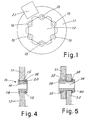
- figure 1 there is shown the disc 11 of a disc brake, mounted on an element 12 fixed to the hub of a wheel to be made,to brake (not shown in the figure) for example of a motorcycle.
- the disc of the brake 11 forms an annular braking track intended to cooperate with the braking pads 21 (shown schematically in the figure) to achieve the braking action of the wheel, according to techniques known in the brakes field.
- the disc of the brake 11 has an annular shape and is fixed to the element 12 that is coupled with the wheel by means of a plurality of constraining elements 13 spaced in a regular manner along the internal perimeter of the disc 11.
- FIG 2 a constraining element 13 between the braking disc 11 and the element 12 coupled with the wheel is shown in detail.
- the element 13 comprises a pawl 14 (shown in the figure with the head removed) received in a seat defined by an open hollow portion 16 of the disc and by an open hollow portion 17 of the element 12 arranged facing the hollow portion 16 of the disc 11.
- an elastically deformable annular element 15 is arranged around the side surface 14a of the pawl 14.
- the annular element 15 remains interposed between the side wall 14a of the pawl 14 and the wall 16a, 17a of the seat in which the constraining element 13 is received, and according to the invention, ensures constraining of the disc on the hub, whilst enabling the disc to stretch locally between constraint and constraint, assisting the deformation thereof (due for example to thermal or mechanical stress).
- FIG 4 a section of the constraining element 13 according to plane IV-IV in figure 2 is shown.
- the pawl 14 (or "pin"), made in the shape of a hollow cylinder, is provided at the ends with a head 19 and with a head 20 for achieving the constraint between the disc 11 and the element 12 in a direction that is perpendicular to the disc of the brake.
- the second head 20 of the pawl 14 could be obtained by riveting, for example with the interposing of a washer 18 between the head 20 and the wall of the disc brake.
- a clip or Seeger ring could be applied to the pawl, according to known solutions in the field of disc brakes.
- the annular element 15 is made from a band of elastic metal material (see figure 2).
- the band 15, sectioned on a plane parallel to the disc, has an undulating pattern to alternatively touch the wall of the seat 16a, 17a and the side wall 14a of the pawl 14.
- the band 15 is such as to touch at at least three different points the wall 16a of the hollow portion 16 of the disc and at at least three points the wall 17a of the hollow portion 17 of the element 12.
- the pawl 14 (cylindrical in shape) is coaxial to the generally cylindrical seat formed by the hollow portions 16 and 17. Furthermore, the disc 11 is not in direct contact with the element 12, there being a small gap between the two elements.
- generally cylindrical seat also refers to seats that have a certain degree of conicity, due, for example, to blanking of the seats.
- the band 15 does not surround the pawl 14 along its entire side surface 14a, but has a notch that is longitudinal to the axis of the pawl.
- This solution enables the band 15 to extend along the perimeter of the pawl 14 when it is compressed and deformed during a corresponding movement between the hollow portion 16 of the disc 11 and the hollow portion 17 of the element 12 or when the constraining element is inserted into its seat by pressing it to impose the necessary preload on the elastic band.
- the disc 11 of the brake is in fact subjected to considerable mechanical and thermal stress due to the action of friction braking on the braking track.
- the stresses can cause local stretching of the disc 11 that vary the distances between two adjacent hollow portions 16 and 17 intended for constraining the disc on the hub.
- the annular elastic element 15 absorbs this stretching, enabling reciprocal movement between the hollow portion 16 and the element 12, preventing curving of the disc.
- Figure 3 shows how the band 15 is deformed by local movement of the braking track 11 to the left.
- the band 15 acts elastically and, when thermal-mechanical stress has terminated, recovers the original position in figure 2, preventing the occurrence of deformation of a permanent type on the disc.
- the elastic action of the annular element 15 enables all the mechanical and thermal stretching generated by braking on the disc 11 to be absorbed, thus ensuring the planarity of the disc in all work conditions.
- annular element enables stress from different angular tilts (both radial and tangential or combinations of the two) to be absorbed.
- Figure 5 shows an alternative embodiment of the present invention, where the pawl 34 is received in a generally cylindrical seat defined by a pair of aligned coaxial closed holes respectively obtained on the element coupled with the wheel 32 and on the disc of the brake 31.
- the pawl 34 as in the preceding case, is provided with a first head 39 and with a riveted head 40 for ensuring the constraint between disc and hub in an axial direction.
- a washer 38 can be arranged between the riveted head 40 and the element 32, according to known techniques in the field of disc brakes.
- the annular elastic element 35 shown schematically in the figure, surrounds the pawl 34 only on the part thereof received in the hole on the disc 31.
- the pawl is rigidly constrained on the element 32, but the disc 31 has a small degree of freedom compared with the pawl, being able to "fluctuate” around the latter, exploiting the deformability of the annular element 35.
- element 35 could be made with an undulating band completely similar to the band disclosed for the main embodiment in figure 2.
- a brake has in fact been provided that is provided with constraining elements fixing the disc of the brake to the wheel to be made to brake that enable the disc to stretch locally between constraint and constraint without undergoing deformation of a permanent nature and without losing planarity.
- the longitudinal notch formed in the elastic band could also not be rectilinear, but could be V-shaped, in order to obtain continuous contact between the wall of the seat and the band along the entire perimeter of the pawl.
- the band may also be peripherally continuous, so without the interruption created by the longitudinal notch, in particular if the radial undulations thereof are accentuated to the point of any way conferring the necessary deformability on the ring.
Landscapes
- Engineering & Computer Science (AREA)
- General Engineering & Computer Science (AREA)
- Mechanical Engineering (AREA)
- Braking Arrangements (AREA)
Abstract
Description
- The present invention relates to a brake for vehicle wheels provided with a particular constraining element between the braking band (consisting, for example, of a disc) on which the brake pads and the wheel to be braked act.
- In the field of vehicles, in particular of motorcycles, fixing the disc of the brake to the hub of the wheel to be made to brake using a series of constraining elements has been known for some time, for example rivets and studs, spaced at regular intervals along the internal circumference of the disc.
- To achieve fixing, each rivet can be received in a suitable generally cylindrical seat defined by a pair of aligned coaxial holes obtained respectively on the hub of the wheel (or on a brake element fixed to the hub) on the braking disc.
- Alternatively, each rivet can be received in a seat half defined by a generally semicylindrical concavity obtained on the hub and half defined by a similar semicylindrical concavity obtained on the disc.
- In all cases, fixing achieved with prior-art rivets imposes rigid constraining of the disc on the hub at several points, generating some significant drawbacks.
- In fact, during braking, great tension inside the braking track of the disc and considerable local temperature increases due to friction are generated; these phenomena may cause local stretching in various zones of the disc.
- With a system of stiff constraints defining a series of fixed points for the braking track, the local stretching that originates in the disc may cause permanent deformation and curving that, over the long term, may cause damage to the brake, great noise and undesired vibrations.
- The general object of the present invention is to overcome the aforementioned drawbacks by providing a brake provided with a constraining system between the element that forms the braking track and the wheel to be made to brake such as to absorb the stretching of the braking track due to mechanical or thermal stress, avoiding permanent deformation or undesired curves.
- A further object of the present invention is to provide a constraining element that has both a simple and economical structure.
- Another object of the present invention is to provide a constraining element that enables the vibrations and noise of the brake to be reduced.
- In view of this object it was decided to make, according to the invention, a brake for vehicle wheels comprising a first element coupled with the wheel and a second element comprising an annular strip on which braking pads act, said first and second element having respective hollow portions intended to correspond to pairs for forming receiving seats of constraining elements, characterized in that said constraining element consists of a substantially cylindrical pawl around the side surface of which there is arranged an elastically deformable annular element intended to remain interposed between the wall of the seat and the side wall of the pawl to enable corresponding movements between the hollow portion of the first element and the hollow portion of the second element of the brake.
- In order to make the explanation of the innovative principles of the present invention and its advantages over the prior art clearer, a possible embodiment applying such principles will be disclosed below with the help of the enclosed drawings. In the drawings:
- figure 1 is a view of a disc brake according to the invention,
- figure 2 is a constraining element fixing the disc of the brake to the hub of the wheel, in rest status,
- figure 3 is a constraining element fixing the disc of the brake to the hub of the wheel, in operating status with stretching deformation of the disc,
- figure 4 is a section view of the constraining element in the preceding figures, sectioned along the plane IV-IV in figure 2,
- figure 5 is a view of an alternative embodiment of the constraining element according to the invention, sectioned according to a plane perpendicular to the plane of the disc.
- With reference to the figures, in figure 1 there is shown the
disc 11 of a disc brake, mounted on anelement 12 fixed to the hub of a wheel to be made,to brake (not shown in the figure) for example of a motorcycle. - The disc of the
brake 11 forms an annular braking track intended to cooperate with the braking pads 21 (shown schematically in the figure) to achieve the braking action of the wheel, according to techniques known in the brakes field. - The disc of the
brake 11 has an annular shape and is fixed to theelement 12 that is coupled with the wheel by means of a plurality of constrainingelements 13 spaced in a regular manner along the internal perimeter of thedisc 11. - In figure 2 a constraining
element 13 between thebraking disc 11 and theelement 12 coupled with the wheel is shown in detail. Theelement 13 comprises a pawl 14 (shown in the figure with the head removed) received in a seat defined by an openhollow portion 16 of the disc and by an openhollow portion 17 of theelement 12 arranged facing thehollow portion 16 of thedisc 11. - Around the
side surface 14a of thepawl 14, an elastically deformableannular element 15 is arranged. - The
annular element 15 remains interposed between theside wall 14a of thepawl 14 and thewall 16a, 17a of the seat in which the constrainingelement 13 is received, and according to the invention, ensures constraining of the disc on the hub, whilst enabling the disc to stretch locally between constraint and constraint, assisting the deformation thereof (due for example to thermal or mechanical stress). - In figure 4 a section of the constraining
element 13 according to plane IV-IV in figure 2 is shown. The pawl 14 (or "pin"), made in the shape of a hollow cylinder, is provided at the ends with ahead 19 and with ahead 20 for achieving the constraint between thedisc 11 and theelement 12 in a direction that is perpendicular to the disc of the brake. - According to prior-art solutions, the
second head 20 of thepawl 14 could be obtained by riveting, for example with the interposing of awasher 18 between thehead 20 and the wall of the disc brake. As an alternative to riveting the head, to make the constraint in the direction that is axial to the pawl, a clip or Seeger ring could be applied to the pawl, according to known solutions in the field of disc brakes. - In an embodiment of the invention, the
annular element 15 is made from a band of elastic metal material (see figure 2). - The
band 15, sectioned on a plane parallel to the disc, has an undulating pattern to alternatively touch the wall of theseat 16a, 17a and theside wall 14a of thepawl 14. - As shown in the figure, the
band 15 is such as to touch at at least three different points thewall 16a of thehollow portion 16 of the disc and at at least three points the wall 17a of thehollow portion 17 of theelement 12. - According to what is shown in figure 2, in the rest position with the annular element in the non-deformed position, the pawl 14 (cylindrical in shape) is coaxial to the generally cylindrical seat formed by the
hollow portions disc 11 is not in direct contact with theelement 12, there being a small gap between the two elements. It should be noted that "generally cylindrical seat" also refers to seats that have a certain degree of conicity, due, for example, to blanking of the seats. - Advantageously, the
band 15 does not surround thepawl 14 along itsentire side surface 14a, but has a notch that is longitudinal to the axis of the pawl. This solution enables theband 15 to extend along the perimeter of thepawl 14 when it is compressed and deformed during a corresponding movement between thehollow portion 16 of thedisc 11 and thehollow portion 17 of theelement 12 or when the constraining element is inserted into its seat by pressing it to impose the necessary preload on the elastic band. - As already mentioned, the
disc 11 of the brake is in fact subjected to considerable mechanical and thermal stress due to the action of friction braking on the braking track. The stresses can cause local stretching of thedisc 11 that vary the distances between two adjacenthollow portions - The annular
elastic element 15 absorbs this stretching, enabling reciprocal movement between thehollow portion 16 and theelement 12, preventing curving of the disc. - Figure 3 shows how the
band 15 is deformed by local movement of thebraking track 11 to the left. - The
band 15 acts elastically and, when thermal-mechanical stress has terminated, recovers the original position in figure 2, preventing the occurrence of deformation of a permanent type on the disc. - The elastic action of the
annular element 15 enables all the mechanical and thermal stretching generated by braking on thedisc 11 to be absorbed, thus ensuring the planarity of the disc in all work conditions. - It should be noted that the annular element enables stress from different angular tilts (both radial and tangential or combinations of the two) to be absorbed.
- Figure 5 shows an alternative embodiment of the present invention, where the
pawl 34 is received in a generally cylindrical seat defined by a pair of aligned coaxial closed holes respectively obtained on the element coupled with thewheel 32 and on the disc of thebrake 31. - The
pawl 34, as in the preceding case, is provided with afirst head 39 and with a rivetedhead 40 for ensuring the constraint between disc and hub in an axial direction. Awasher 38 can be arranged between the rivetedhead 40 and theelement 32, according to known techniques in the field of disc brakes. - In the embodiment in figure 5 the annular
elastic element 35, shown schematically in the figure, surrounds thepawl 34 only on the part thereof received in the hole on thedisc 31. In this way the pawl is rigidly constrained on theelement 32, but thedisc 31 has a small degree of freedom compared with the pawl, being able to "fluctuate" around the latter, exploiting the deformability of theannular element 35. - It should be noted that the
element 35 could be made with an undulating band completely similar to the band disclosed for the main embodiment in figure 2. - At this point it is clear how the objects of the present invention have been achieved.
- A brake has in fact been provided that is provided with constraining elements fixing the disc of the brake to the wheel to be made to brake that enable the disc to stretch locally between constraint and constraint without undergoing deformation of a permanent nature and without losing planarity.
- Lastly, a constraining element has been provided that dampens all the vibration that may be induced on the disc and considerably limits the noise from rolling of the brake.
- Naturally, the above disclosure of an embodiment applying the innovative principles of the present invention is provided by way of example of such principles and must not therefore be taken to limit the scope of the invention claimed herein. The longitudinal notch formed in the elastic band could also not be rectilinear, but could be V-shaped, in order to obtain continuous contact between the wall of the seat and the band along the entire perimeter of the pawl.
- The band may also be peripherally continuous, so without the interruption created by the longitudinal notch, in particular if the radial undulations thereof are accentuated to the point of any way conferring the necessary deformability on the ring.
Claims (19)
- Brake for vehicle wheels comprising a first element coupled with the wheel and a second element comprising an annular strip on which braking pads act, said first and second element having respective hollow portions (16, 17) intended to correspond to pairs for forming housing seats of constraining elements, characterized in that said constraining element consists of a substantially cylindrical pawl around the side surface (14a) of which an elastically deformable annular element (15) is arranged intended to remain interposed between the wall of the seat and the side wall (14a) of the pawl to enable corresponding movements between the hollow portion of the first element and the hollow portion of the second element.
- Brake according to claim 1, characterized in that said hollow portions are open concavities (16, 17) intended to be made to face one another in pairs to define a hole that makes said housing seat of the constraining element.
- Brake according to claim 1, characterized in that said seat is a through hole and the constraining element (14) is provided with a head on each of the two ends protruding on opposite sides of the seat, to make the connection between the first and the second element in an axial direction in relation to the pawl.
- Brake according to claim 3, characterized in that a head is obtained for riveting the pawl inserted into the seat.
- Brake according to claim 1, characterized in that said annular element (15) is made of an elastic band, said band being sectioned according to a plane that is perpendicular to the axis of the pawl having an undulating profile for alternatively resting on the surface of the seat and on the side surface of the pawl (14).
- Brake according to claim 5, characterized in that said band (15) has six points of contact with the wall of the seat and six points of contact with the side surface of the pawl (14).
- Brake according to claim 5, characterized in that said band (15) has a notch longitudinally to the pawl to enable the tangential expansion of the band (15) along the perimeter of the pawl (14) through radial deformation within the seat.
- Brake according to claim 5, characterized in that the elastic band (15) is made of metal material.
- Brake according to claim 1, characterized in that said seat is generally circular cylindrical.
- Brake according to claim 1, characterized in that said pawl is circular cylindrical.
- Brake according to claim 9 and 10, characterized in that when the annular element (15) is in the non-deformed position the pawl (14) is coaxial to said seat.
- Brake according to claim 2, characterized in that the two brake elements are not in direct contact with one another when the annular elastic element (15) is in the non-deformed position.
- Brake according to claim 1, characterized in that said hollow portions are closed holes obtained respectively in the first and the second element, intended to be aligned in pairs when they correspond to form said receiving seat of the constraining element.
- Brake according to claim 13, characterized in that the annular element is arranged between the side wall of the pawl and the internal wall of only one of the two holes that form the seat.
- Brake according to claim 1, characterized in that the second element of the brake is a disc.
- Brake according to claim 1, characterized in that the first element of the brake is fixed to the hub of the wheel to be made to brake.
- Brake according to claim 3, characterized in that a head of the pawl is obtained by applying a clip or a Seeger ring to the pawl.
- Brake according to claim 7, characterized in that the longitudinal notch in the elastic band is V-shaped, to ensure the continuity of the contact between the wall of the seat and the band along the perimeter of the pawl.
- Brake according to claim 5, characterized in that the band has a continuous profile for surrounding the side wall of the pawl without interruptions or notches.
Applications Claiming Priority (1)
| Application Number | Priority Date | Filing Date | Title |
|---|---|---|---|
| IT000016U ITMI20050016U1 (en) | 2005-01-25 | 2005-01-25 | BRAKE FOR WHEELS OF VEHICLES EQUIPPED WITH ELEMENTS OF BOND OF THE BRAKING ELASTIC BEHAVIOR |
Publications (2)
| Publication Number | Publication Date |
|---|---|
| EP1683984A1 true EP1683984A1 (en) | 2006-07-26 |
| EP1683984B1 EP1683984B1 (en) | 2017-03-08 |
Family
ID=36201037
Family Applications (1)
| Application Number | Title | Priority Date | Filing Date |
|---|---|---|---|
| EP06001085.7A Expired - Lifetime EP1683984B1 (en) | 2005-01-25 | 2006-01-19 | Brake for vehicle wheels provided with constraining elements of the elastically operating braking band |
Country Status (5)
| Country | Link |
|---|---|
| US (1) | US20060163012A1 (en) |
| EP (1) | EP1683984B1 (en) |
| JP (1) | JP5119598B2 (en) |
| ES (1) | ES2627853T3 (en) |
| IT (1) | ITMI20050016U1 (en) |
Cited By (1)
| Publication number | Priority date | Publication date | Assignee | Title |
|---|---|---|---|---|
| EP3203103A1 (en) | 2016-01-08 | 2017-08-09 | Triumph Designs Limited | Brake disc |
Families Citing this family (1)
| Publication number | Priority date | Publication date | Assignee | Title |
|---|---|---|---|---|
| TWI722943B (en) * | 2020-07-16 | 2021-03-21 | 許再勝 | Floating dish |
Citations (5)
| Publication number | Priority date | Publication date | Assignee | Title |
|---|---|---|---|---|
| DE1775685A1 (en) * | 1968-09-10 | 1971-09-16 | Teves Gmbh Alfred | Brake disc |
| FR2266052A1 (en) * | 1974-04-01 | 1975-10-24 | Girling Ltd | Railway vehicle brake disc and hub - deformable section allows radial contraction of disc onto hub |
| US4967893A (en) * | 1988-12-09 | 1990-11-06 | Borg-Warner Automotive Gmbh | Friction assembly |
| US5520269A (en) * | 1993-02-10 | 1996-05-28 | Kabushiki Kaishia Yutaka Giken | Floating type brake disk assembly |
| US6116386A (en) * | 1997-06-27 | 2000-09-12 | Dr. Ing. H.C.F. Porsche Ag | Divided brake disk for thermal compensation |
Family Cites Families (7)
| Publication number | Priority date | Publication date | Assignee | Title |
|---|---|---|---|---|
| IT984360B (en) * | 1972-03-06 | 1974-11-20 | Star Kugelhalter Gmbh Dt | INSERT ELEMENT INTERPOSABLE BETWEEN MACHINE PARTS FOR CONNECTION PURPOSE |
| JPS627000Y2 (en) * | 1980-06-27 | 1987-02-18 | ||
| JPS61241538A (en) * | 1985-04-19 | 1986-10-27 | Yamaha Motor Co Ltd | Floating type brake disc support mechanism |
| US4790683A (en) * | 1987-10-05 | 1988-12-13 | Cramer Jr Arthur A | Tolerance ring and shim and method of use |
| JPH0581544U (en) * | 1992-04-03 | 1993-11-05 | 株式会社ユタカ技研 | Floating brake disc |
| DE10253642A1 (en) * | 2002-11-18 | 2004-06-03 | Knorr-Bremse Systeme für Nutzfahrzeuge GmbH | Disc brake, in particular for a commercial vehicle |
| JP4236506B2 (en) * | 2003-04-18 | 2009-03-11 | 曙ブレーキ工業株式会社 | Railway vehicle brake disc and rail vehicle wheel with brake disc |
-
2005
- 2005-01-25 IT IT000016U patent/ITMI20050016U1/en unknown
-
2006
- 2006-01-19 EP EP06001085.7A patent/EP1683984B1/en not_active Expired - Lifetime
- 2006-01-19 ES ES06001085.7T patent/ES2627853T3/en not_active Expired - Lifetime
- 2006-01-24 US US11/337,479 patent/US20060163012A1/en not_active Abandoned
- 2006-01-25 JP JP2006016284A patent/JP5119598B2/en not_active Expired - Fee Related
Patent Citations (5)
| Publication number | Priority date | Publication date | Assignee | Title |
|---|---|---|---|---|
| DE1775685A1 (en) * | 1968-09-10 | 1971-09-16 | Teves Gmbh Alfred | Brake disc |
| FR2266052A1 (en) * | 1974-04-01 | 1975-10-24 | Girling Ltd | Railway vehicle brake disc and hub - deformable section allows radial contraction of disc onto hub |
| US4967893A (en) * | 1988-12-09 | 1990-11-06 | Borg-Warner Automotive Gmbh | Friction assembly |
| US5520269A (en) * | 1993-02-10 | 1996-05-28 | Kabushiki Kaishia Yutaka Giken | Floating type brake disk assembly |
| US6116386A (en) * | 1997-06-27 | 2000-09-12 | Dr. Ing. H.C.F. Porsche Ag | Divided brake disk for thermal compensation |
Cited By (1)
| Publication number | Priority date | Publication date | Assignee | Title |
|---|---|---|---|---|
| EP3203103A1 (en) | 2016-01-08 | 2017-08-09 | Triumph Designs Limited | Brake disc |
Also Published As
| Publication number | Publication date |
|---|---|
| EP1683984B1 (en) | 2017-03-08 |
| ITMI20050016U1 (en) | 2006-07-26 |
| JP5119598B2 (en) | 2013-01-16 |
| JP2006207816A (en) | 2006-08-10 |
| US20060163012A1 (en) | 2006-07-27 |
| ES2627853T3 (en) | 2017-07-31 |
Similar Documents
| Publication | Publication Date | Title |
|---|---|---|
| JP6226984B2 (en) | Wheel brake disc | |
| JP4941126B2 (en) | Sound insulation cover | |
| US4108286A (en) | Brake disc for an axle of a railway vehicle | |
| CA2920060C (en) | Friction ring body for a rail wheel brake and rail wheel brake | |
| US20080277998A1 (en) | Wheel rim | |
| TWI727445B (en) | Installation structure of brake disc for railway vehicle and brake disc unit using the installation structure | |
| EP1683984B1 (en) | Brake for vehicle wheels provided with constraining elements of the elastically operating braking band | |
| CN110641226A (en) | Elastic wheel noise reduction damper and assembling and mounting method thereof | |
| JP5848558B2 (en) | Disc rotor unit for vehicles | |
| CN101495326A (en) | Device for reducing railway wheel noise when moving on rail | |
| US7374025B2 (en) | Brake Disc | |
| KR100931720B1 (en) | Heat conduction ring on wheel assembly | |
| CN110962502B (en) | Elastic wheel for railway vehicle, use method of elastic wheel and independent wheel set | |
| JP2009250325A (en) | Noise-reduction brake disc | |
| JP3926450B2 (en) | Elastic wheels for railway vehicles | |
| JP5510513B2 (en) | Braking device | |
| JP4236506B2 (en) | Railway vehicle brake disc and rail vehicle wheel with brake disc | |
| KR100448785B1 (en) | trailing arm bush of vehicle | |
| EP3051168B1 (en) | Ventilated brake disk for a motor vehicle | |
| JP2007113785A (en) | Motion transmission system with sprocket supported by elastic anti-jerk element | |
| US7552805B2 (en) | Braking disc with irregular profile and brake comprising this disc | |
| KR20170070932A (en) | One body type assembly of brake disk and hub bearing | |
| JP6941167B2 (en) | brake disc | |
| KR101167680B1 (en) | insulator for automotive exhaust system and the same manufacturing method | |
| KR200170602Y1 (en) | Thermal breaker to prevent tire damage |
Legal Events
| Date | Code | Title | Description |
|---|---|---|---|
| PUAI | Public reference made under article 153(3) epc to a published international application that has entered the european phase |
Free format text: ORIGINAL CODE: 0009012 |
|
| AK | Designated contracting states |
Kind code of ref document: A1 Designated state(s): AT BE BG CH CY CZ DE DK EE ES FI FR GB GR HU IE IS IT LI LT LU LV MC NL PL PT RO SE SI SK TR |
|
| AX | Request for extension of the european patent |
Extension state: AL BA HR MK YU |
|
| 17P | Request for examination filed |
Effective date: 20070125 |
|
| 17Q | First examination report despatched |
Effective date: 20070223 |
|
| AKX | Designation fees paid |
Designated state(s): AT BE BG CH CY CZ DE DK EE ES FI FR GB GR HU IE IS IT LI LT LU LV MC NL PL PT RO SE SI SK TR |
|
| GRAP | Despatch of communication of intention to grant a patent |
Free format text: ORIGINAL CODE: EPIDOSNIGR1 |
|
| INTG | Intention to grant announced |
Effective date: 20160923 |
|
| RAP1 | Party data changed (applicant data changed or rights of an application transferred) |
Owner name: SUNSTAR SINGAPORE PTE. LTD. |
|
| GRAS | Grant fee paid |
Free format text: ORIGINAL CODE: EPIDOSNIGR3 |
|
| STAA | Information on the status of an ep patent application or granted ep patent |
Free format text: STATUS: GRANT OF PATENT IS INTENDED |
|
| GRAA | (expected) grant |
Free format text: ORIGINAL CODE: 0009210 |
|
| STAA | Information on the status of an ep patent application or granted ep patent |
Free format text: STATUS: THE PATENT HAS BEEN GRANTED |
|
| AK | Designated contracting states |
Kind code of ref document: B1 Designated state(s): AT BE BG CH CY CZ DE DK EE ES FI FR GB GR HU IE IS IT LI LT LU LV MC NL PL PT RO SE SI SK TR |
|
| REG | Reference to a national code |
Ref country code: GB Ref legal event code: FG4D |
|
| REG | Reference to a national code |
Ref country code: CH Ref legal event code: EP Ref country code: AT Ref legal event code: REF Ref document number: 873819 Country of ref document: AT Kind code of ref document: T Effective date: 20170315 |
|
| REG | Reference to a national code |
Ref country code: IE Ref legal event code: FG4D |
|
| REG | Reference to a national code |
Ref country code: DE Ref legal event code: R096 Ref document number: 602006051880 Country of ref document: DE |
|
| REG | Reference to a national code |
Ref country code: LT Ref legal event code: MG4D |
|
| REG | Reference to a national code |
Ref country code: NL Ref legal event code: MP Effective date: 20170308 |
|
| PG25 | Lapsed in a contracting state [announced via postgrant information from national office to epo] |
Ref country code: FI Free format text: LAPSE BECAUSE OF FAILURE TO SUBMIT A TRANSLATION OF THE DESCRIPTION OR TO PAY THE FEE WITHIN THE PRESCRIBED TIME-LIMIT Effective date: 20170308 Ref country code: LT Free format text: LAPSE BECAUSE OF FAILURE TO SUBMIT A TRANSLATION OF THE DESCRIPTION OR TO PAY THE FEE WITHIN THE PRESCRIBED TIME-LIMIT Effective date: 20170308 Ref country code: GR Free format text: LAPSE BECAUSE OF FAILURE TO SUBMIT A TRANSLATION OF THE DESCRIPTION OR TO PAY THE FEE WITHIN THE PRESCRIBED TIME-LIMIT Effective date: 20170609 |
|
| REG | Reference to a national code |
Ref country code: ES Ref legal event code: FG2A Ref document number: 2627853 Country of ref document: ES Kind code of ref document: T3 Effective date: 20170731 |
|
| REG | Reference to a national code |
Ref country code: AT Ref legal event code: MK05 Ref document number: 873819 Country of ref document: AT Kind code of ref document: T Effective date: 20170308 |
|
| PG25 | Lapsed in a contracting state [announced via postgrant information from national office to epo] |
Ref country code: BG Free format text: LAPSE BECAUSE OF FAILURE TO SUBMIT A TRANSLATION OF THE DESCRIPTION OR TO PAY THE FEE WITHIN THE PRESCRIBED TIME-LIMIT Effective date: 20170608 Ref country code: LV Free format text: LAPSE BECAUSE OF FAILURE TO SUBMIT A TRANSLATION OF THE DESCRIPTION OR TO PAY THE FEE WITHIN THE PRESCRIBED TIME-LIMIT Effective date: 20170308 Ref country code: SE Free format text: LAPSE BECAUSE OF FAILURE TO SUBMIT A TRANSLATION OF THE DESCRIPTION OR TO PAY THE FEE WITHIN THE PRESCRIBED TIME-LIMIT Effective date: 20170308 |
|
| PG25 | Lapsed in a contracting state [announced via postgrant information from national office to epo] |
Ref country code: NL Free format text: LAPSE BECAUSE OF FAILURE TO SUBMIT A TRANSLATION OF THE DESCRIPTION OR TO PAY THE FEE WITHIN THE PRESCRIBED TIME-LIMIT Effective date: 20170308 |
|
| PG25 | Lapsed in a contracting state [announced via postgrant information from national office to epo] |
Ref country code: EE Free format text: LAPSE BECAUSE OF FAILURE TO SUBMIT A TRANSLATION OF THE DESCRIPTION OR TO PAY THE FEE WITHIN THE PRESCRIBED TIME-LIMIT Effective date: 20170308 Ref country code: AT Free format text: LAPSE BECAUSE OF FAILURE TO SUBMIT A TRANSLATION OF THE DESCRIPTION OR TO PAY THE FEE WITHIN THE PRESCRIBED TIME-LIMIT Effective date: 20170308 Ref country code: SK Free format text: LAPSE BECAUSE OF FAILURE TO SUBMIT A TRANSLATION OF THE DESCRIPTION OR TO PAY THE FEE WITHIN THE PRESCRIBED TIME-LIMIT Effective date: 20170308 Ref country code: RO Free format text: LAPSE BECAUSE OF FAILURE TO SUBMIT A TRANSLATION OF THE DESCRIPTION OR TO PAY THE FEE WITHIN THE PRESCRIBED TIME-LIMIT Effective date: 20170308 Ref country code: CZ Free format text: LAPSE BECAUSE OF FAILURE TO SUBMIT A TRANSLATION OF THE DESCRIPTION OR TO PAY THE FEE WITHIN THE PRESCRIBED TIME-LIMIT Effective date: 20170308 |
|
| PG25 | Lapsed in a contracting state [announced via postgrant information from national office to epo] |
Ref country code: PL Free format text: LAPSE BECAUSE OF FAILURE TO SUBMIT A TRANSLATION OF THE DESCRIPTION OR TO PAY THE FEE WITHIN THE PRESCRIBED TIME-LIMIT Effective date: 20170308 Ref country code: PT Free format text: LAPSE BECAUSE OF FAILURE TO SUBMIT A TRANSLATION OF THE DESCRIPTION OR TO PAY THE FEE WITHIN THE PRESCRIBED TIME-LIMIT Effective date: 20170710 Ref country code: IS Free format text: LAPSE BECAUSE OF FAILURE TO SUBMIT A TRANSLATION OF THE DESCRIPTION OR TO PAY THE FEE WITHIN THE PRESCRIBED TIME-LIMIT Effective date: 20170708 |
|
| REG | Reference to a national code |
Ref country code: FR Ref legal event code: PLFP Year of fee payment: 13 Ref country code: DE Ref legal event code: R097 Ref document number: 602006051880 Country of ref document: DE |
|
| PLBE | No opposition filed within time limit |
Free format text: ORIGINAL CODE: 0009261 |
|
| STAA | Information on the status of an ep patent application or granted ep patent |
Free format text: STATUS: NO OPPOSITION FILED WITHIN TIME LIMIT |
|
| PG25 | Lapsed in a contracting state [announced via postgrant information from national office to epo] |
Ref country code: DK Free format text: LAPSE BECAUSE OF FAILURE TO SUBMIT A TRANSLATION OF THE DESCRIPTION OR TO PAY THE FEE WITHIN THE PRESCRIBED TIME-LIMIT Effective date: 20170308 |
|
| 26N | No opposition filed |
Effective date: 20171211 |
|
| PG25 | Lapsed in a contracting state [announced via postgrant information from national office to epo] |
Ref country code: SI Free format text: LAPSE BECAUSE OF FAILURE TO SUBMIT A TRANSLATION OF THE DESCRIPTION OR TO PAY THE FEE WITHIN THE PRESCRIBED TIME-LIMIT Effective date: 20170308 Ref country code: IT Free format text: LAPSE BECAUSE OF FAILURE TO SUBMIT A TRANSLATION OF THE DESCRIPTION OR TO PAY THE FEE WITHIN THE PRESCRIBED TIME-LIMIT Effective date: 20170308 |
|
| REG | Reference to a national code |
Ref country code: CH Ref legal event code: PL |
|
| PG25 | Lapsed in a contracting state [announced via postgrant information from national office to epo] |
Ref country code: LU Free format text: LAPSE BECAUSE OF NON-PAYMENT OF DUE FEES Effective date: 20180119 |
|
| REG | Reference to a national code |
Ref country code: IE Ref legal event code: MM4A |
|
| REG | Reference to a national code |
Ref country code: BE Ref legal event code: MM Effective date: 20180131 |
|
| PG25 | Lapsed in a contracting state [announced via postgrant information from national office to epo] |
Ref country code: BE Free format text: LAPSE BECAUSE OF NON-PAYMENT OF DUE FEES Effective date: 20180131 Ref country code: LI Free format text: LAPSE BECAUSE OF NON-PAYMENT OF DUE FEES Effective date: 20180131 Ref country code: CH Free format text: LAPSE BECAUSE OF NON-PAYMENT OF DUE FEES Effective date: 20180131 |
|
| PG25 | Lapsed in a contracting state [announced via postgrant information from national office to epo] |
Ref country code: IE Free format text: LAPSE BECAUSE OF NON-PAYMENT OF DUE FEES Effective date: 20180119 |
|
| PG25 | Lapsed in a contracting state [announced via postgrant information from national office to epo] |
Ref country code: MC Free format text: LAPSE BECAUSE OF FAILURE TO SUBMIT A TRANSLATION OF THE DESCRIPTION OR TO PAY THE FEE WITHIN THE PRESCRIBED TIME-LIMIT Effective date: 20170308 |
|
| PG25 | Lapsed in a contracting state [announced via postgrant information from national office to epo] |
Ref country code: TR Free format text: LAPSE BECAUSE OF FAILURE TO SUBMIT A TRANSLATION OF THE DESCRIPTION OR TO PAY THE FEE WITHIN THE PRESCRIBED TIME-LIMIT Effective date: 20170308 |
|
| PG25 | Lapsed in a contracting state [announced via postgrant information from national office to epo] |
Ref country code: HU Free format text: LAPSE BECAUSE OF FAILURE TO SUBMIT A TRANSLATION OF THE DESCRIPTION OR TO PAY THE FEE WITHIN THE PRESCRIBED TIME-LIMIT; INVALID AB INITIO Effective date: 20060119 |
|
| PG25 | Lapsed in a contracting state [announced via postgrant information from national office to epo] |
Ref country code: CY Free format text: LAPSE BECAUSE OF FAILURE TO SUBMIT A TRANSLATION OF THE DESCRIPTION OR TO PAY THE FEE WITHIN THE PRESCRIBED TIME-LIMIT Effective date: 20170308 |
|
| PGFP | Annual fee paid to national office [announced via postgrant information from national office to epo] |
Ref country code: FR Payment date: 20211216 Year of fee payment: 17 Ref country code: GB Payment date: 20211203 Year of fee payment: 17 |
|
| PGFP | Annual fee paid to national office [announced via postgrant information from national office to epo] |
Ref country code: DE Payment date: 20211130 Year of fee payment: 17 |
|
| PGFP | Annual fee paid to national office [announced via postgrant information from national office to epo] |
Ref country code: ES Payment date: 20220203 Year of fee payment: 17 |
|
| REG | Reference to a national code |
Ref country code: DE Ref legal event code: R119 Ref document number: 602006051880 Country of ref document: DE |
|
| GBPC | Gb: european patent ceased through non-payment of renewal fee |
Effective date: 20230119 |
|
| PG25 | Lapsed in a contracting state [announced via postgrant information from national office to epo] |
Ref country code: GB Free format text: LAPSE BECAUSE OF NON-PAYMENT OF DUE FEES Effective date: 20230119 Ref country code: DE Free format text: LAPSE BECAUSE OF NON-PAYMENT OF DUE FEES Effective date: 20230801 |
|
| PG25 | Lapsed in a contracting state [announced via postgrant information from national office to epo] |
Ref country code: FR Free format text: LAPSE BECAUSE OF NON-PAYMENT OF DUE FEES Effective date: 20230131 |
|
| REG | Reference to a national code |
Ref country code: ES Ref legal event code: FD2A Effective date: 20240402 |
|
| PG25 | Lapsed in a contracting state [announced via postgrant information from national office to epo] |
Ref country code: ES Free format text: LAPSE BECAUSE OF NON-PAYMENT OF DUE FEES Effective date: 20230120 |
|
| PG25 | Lapsed in a contracting state [announced via postgrant information from national office to epo] |
Ref country code: ES Free format text: LAPSE BECAUSE OF NON-PAYMENT OF DUE FEES Effective date: 20230120 |