EP1683907A1 - Contact band for a moisture measuring circuit and dryer provided therewith - Google Patents
Contact band for a moisture measuring circuit and dryer provided therewith Download PDFInfo
- Publication number
- EP1683907A1 EP1683907A1 EP05100441A EP05100441A EP1683907A1 EP 1683907 A1 EP1683907 A1 EP 1683907A1 EP 05100441 A EP05100441 A EP 05100441A EP 05100441 A EP05100441 A EP 05100441A EP 1683907 A1 EP1683907 A1 EP 1683907A1
- Authority
- EP
- European Patent Office
- Prior art keywords
- contact band
- band
- notch
- rib
- strip
- Prior art date
- Legal status (The legal status is an assumption and is not a legal conclusion. Google has not performed a legal analysis and makes no representation as to the accuracy of the status listed.)
- Withdrawn
Links
- 238000001035 drying Methods 0.000 claims abstract description 9
- 239000004020 conductor Substances 0.000 claims abstract description 3
- 230000000284 resting effect Effects 0.000 claims 1
- 238000005259 measurement Methods 0.000 description 5
- 238000003466 welding Methods 0.000 description 3
- 244000145845 chattering Species 0.000 description 2
- 238000004519 manufacturing process Methods 0.000 description 2
- 230000003252 repetitive effect Effects 0.000 description 2
- 238000005406 washing Methods 0.000 description 2
- 238000004891 communication Methods 0.000 description 1
- 238000010276 construction Methods 0.000 description 1
- 238000005520 cutting process Methods 0.000 description 1
- 238000003780 insertion Methods 0.000 description 1
- 230000037431 insertion Effects 0.000 description 1
- 238000005304 joining Methods 0.000 description 1
- 238000000034 method Methods 0.000 description 1
- 238000012545 processing Methods 0.000 description 1
- 238000006467 substitution reaction Methods 0.000 description 1
Images



Classifications
-
- D—TEXTILES; PAPER
- D06—TREATMENT OF TEXTILES OR THE LIKE; LAUNDERING; FLEXIBLE MATERIALS NOT OTHERWISE PROVIDED FOR
- D06F—LAUNDERING, DRYING, IRONING, PRESSING OR FOLDING TEXTILE ARTICLES
- D06F34/00—Details of control systems for washing machines, washer-dryers or laundry dryers
- D06F34/14—Arrangements for detecting or measuring specific parameters
- D06F34/18—Condition of the laundry, e.g. nature or weight
-
- D—TEXTILES; PAPER
- D06—TREATMENT OF TEXTILES OR THE LIKE; LAUNDERING; FLEXIBLE MATERIALS NOT OTHERWISE PROVIDED FOR
- D06F—LAUNDERING, DRYING, IRONING, PRESSING OR FOLDING TEXTILE ARTICLES
- D06F2103/00—Parameters monitored or detected for the control of domestic laundry washing machines, washer-dryers or laundry dryers
- D06F2103/02—Characteristics of laundry or load
- D06F2103/08—Humidity
- D06F2103/10—Humidity expressed as capacitance or resistance
-
- D—TEXTILES; PAPER
- D06—TREATMENT OF TEXTILES OR THE LIKE; LAUNDERING; FLEXIBLE MATERIALS NOT OTHERWISE PROVIDED FOR
- D06F—LAUNDERING, DRYING, IRONING, PRESSING OR FOLDING TEXTILE ARTICLES
- D06F2103/00—Parameters monitored or detected for the control of domestic laundry washing machines, washer-dryers or laundry dryers
- D06F2103/44—Current or voltage
-
- D—TEXTILES; PAPER
- D06—TREATMENT OF TEXTILES OR THE LIKE; LAUNDERING; FLEXIBLE MATERIALS NOT OTHERWISE PROVIDED FOR
- D06F—LAUNDERING, DRYING, IRONING, PRESSING OR FOLDING TEXTILE ARTICLES
- D06F58/00—Domestic laundry dryers
- D06F58/32—Control of operations performed in domestic laundry dryers
- D06F58/34—Control of operations performed in domestic laundry dryers characterised by the purpose or target of the control
- D06F58/46—Control of the operating time
Definitions
- the present invention relates to a contact band for a moisture measuring circuit and to a dryer provided therewith.
- a laundry dryer or in the drying process of a washing/drying machine is very important to measure the degree of clothes dryness to establish the duration of the drying cycle.
- a laundry dryer or a washing/drying machine is generally provided with an electric circuit for measuring the moisture content remaining in the clothes as a function of electrical conductivity or resistance.
- the circuit to carry out the moisture measurement generally comprises an electrically conductive contact band supported on the annular wall of the dryer drum.
- the band is electrically insulated from the drum by an electrically non-conductive pad bonded to the drum and interposed intermediate the band and the drum.
- the band is electrically connected to the drum internal region where the clothes to be dried are placed by means of the vanes disposed on the drum internal surface.
- a scanning arm carrying a brush is mounted on the machine cabinet such that the brush can engage the conductive band.
- the brush is electrically connected to a control unit which is also in contact with an electrical terminal in electrical communication with said drum internal region.
- control unit can calculate the resistance and/or the conductivity of said clothes thereby determining the appropriate duration of the drying cycle.
- the contact bands used in this kind of circuits is formed by a flat strip wrapped around the drum having its ends joined together.
- There are many ways for joining said ends An example is shown in the Patent Application DE 19732951 A1 in which the band ends having a slant edge are joined by means of pliable joint means.
- This kind of junction has been found to be quite noisy in working conditions because of the periodical passage of the electrical brush from one end edge to the other. Even though the band ends are provided with a slant edge in order to make said passage less abrupt, a repetitive noise is generated because a discontinuity is always present between the two bend ends.
- a further drawback of the cited contact band consists in that, even if little, a physical discontinuity is always present between the band ends and this causes the brush to chatter every time the ends pass under the brush. Brush chattering interrupts temporary and repeatedly the electric contact and the clothes moisture measurement cannot be carried out appropriately.
- Another object of the present invention is to provide a contact band able to ensure a reliable measurement of the clothes moisture.
- a further object of the present invention is to provide a contact band easy to be mounted and dismantled without requiring the drum to be removed from the dryer cabinet.
- Still another object of the present invention is to provide a contact band easy to be produced the same band preventing the wear of the electrical brush on which the band slides.
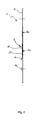
- Figure 1 shows a schematic view of the contact band according to the present invention
- Figure 2 shows a sectional view taken along the line II-II of figure 1 of an end portion of the contact band
- Figure 3 shows the contact band of figure 1 mounted on a dryer drum
- Figure 3a shows an enlarged perspective view of the particular III of figure 3;
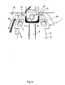
- Figure 4 shows the contact band of figure 1 in a first operative moment
- Figure 5 shows the contact band of figure 1 in a second operative moment
- the contact band 1 for a moisture measuring circuit is shown.
- the contact band 1 comprises a flexible strip 2 made of an electrically conductive material obtained by cutting a metallic sheet.
- the strip 2 has a first end 3 provided with a notch 4 extending prevalently along the longitudinal direction of the strip 2 starting from its transversal edge 5. Since the strip 2 must be associated to a rotating drum of a laundry dryer, as it will be described in grater detail below, the contact band 1 is provided with apertures 6 through which fastening means of know type can pass.
- a second end 7 of the contact band 1 has a rib 8 extending along the longitudinal direction of the strip 2.
- the rib 8 is formed so as to be inserted in the notch 4. Even if the embodiment presented in the attached figures shows a single rib 8 partly received within the notch 4 it is possible to provide a contact band 1 having more than one rib 8 where a corresponding number of notches 4 can be placed.
- the first end 3 comprises seats 10 that are engaged by pliable tabs 11 formed an the second end 7 of the strip 2. If desired the seats 10 can be formed on the second end 7 and the tabs 11 on the first end 3.
- the contact band 1 When the contact band 1 has been wrapped around a drum 12 of a laundry dryer 9, the two ends 3, 7 of the strip 2 are, at least partly, overlapped placing the rib 8 in the notch 4.
- the contact band 1 comprises aligning means 13, preferably in the form of a plurality of lugs 14 formed on either of the first and second end 3, 7 and a corresponding number of slots 15 provided on the other of said end 3, 7 that receive the lugs 14.
- the pliable tabs 11 are folded onto themselves receiving the seats (10) in-between. Folding the tabs 11 a traction is exerted on the strip 2 thereby allowing the contact band 1 to be tightly wrapped around the dryer drum 12. Further fastening means of known type will be passed through the apertures 6 and fixed on the drum 12. Said fastening means will be appropriately insulated in order not to put the band 1 in electrical contact with the drum.
- FIG. 1 it can be seen that between the contact band 1 and the surface of the dryer drum 12 there is an electrically non-conductive pad 16 for electrically insulating the band 1 from the drum 12.
- the band 1 is electrically connected to the drum internal region 18 where the clothes to be dried are placed by means of the vanes 17 disposed on the drum internal surface 19, in this way an electrical current supplied to the drum 12 by means of an electrical circuit 20 passes through the wet clothes to be dried and can return to the power supplying means by the contact band 1 sliding on a brush 22.
- a processing unit 21 is electrically connected between the drum 12 and the brush 22 for measuring an electrical quantity such as a voltage, a resistance or a current intensity. In this way the degree of dryness of the laundry can be known during the whole operation of the drying machine 9.
- the rib 8 provided on the second end 7 of the strip 2 comprises a curved profile 23.
- the curved profile 23 has one or more radii of curvature R 1 and R 2 which are substantially perpendicular to the plane defined by the strip 2, as shown in figure 2.
- the most appropriate radii of curvature can be chosen as desired, provided that the rib 8 rises from the strip 2 and draws into the latter progressively forming a portion 28 where the distance of the curved profile surface from the strip plane is maximum. If the strip 2 comprises more than one rib 8, each of them can have the same curved profile 23 or even different profiles having each the most appropriate radii of curvature in order to allow a smooth passage of the connection between the ends 3 and 7 under the brush 22.
- the notch 4 goes on and leaves the brush 22 while the rib 8 begins to touch the central region 26 of the brush 22.
- the curved profile 23 is dimensioned such that for some degrees of drum rotation all the regions 24, 25, 26 of the brush 22 are in electrical contact with the strip 2. This is obtained providing that, when the contact band 1 is wrapped around the drum 12 and the ends 3, 7 are joined together, the portion 28 of the curved profile 23 rests at a position within the notch 4.
- the length of the rib 8 is at least two times the length of the notch 4.
- FIG 5 it is shown the moment in which the brush 22 has left the first end 3 of the contact band 1 and has passed to the second end 7 carrying the rib 8. From this moment on, the curved profile 23, drawing into the strip 2 progressively, drives the brush 22 to complete the passage across the connection between the end 3, 7 of the strip 2 without chattering.
- the contact band 1 according to the present invention provides significant advantage of ensuring a reliable measurement of the clothes moisture avoiding the production of noise when the laundry dryer is working.
- the contact band of the present invention is very easy to be produced and to be mounted in a drying machine without requiring complicate operations.
Landscapes
- Engineering & Computer Science (AREA)
- Textile Engineering (AREA)
- Detail Structures Of Washing Machines And Dryers (AREA)
Abstract
A contact band (1) for a moisture measuring circuit of a drying machine comprises a flexible strip (2) of an electrically conductive material, a first end (3) having at least a notch (4) and a second end (7); the contact band (1) is characterised in that the second end (7) comprises at least a rib (8) adapted to be inserted in the notch (4). A laundry dryer (9) comprising an improved contact band (1) is further disclosed.
Description
- The present invention relates to a contact band for a moisture measuring circuit and to a dryer provided therewith.
- In a laundry dryer or in the drying process of a washing/drying machine is very important to measure the degree of clothes dryness to establish the duration of the drying cycle. For this aim, a laundry dryer or a washing/drying machine is generally provided with an electric circuit for measuring the moisture content remaining in the clothes as a function of electrical conductivity or resistance.
- The circuit to carry out the moisture measurement generally comprises an electrically conductive contact band supported on the annular wall of the dryer drum. The band is electrically insulated from the drum by an electrically non-conductive pad bonded to the drum and interposed intermediate the band and the drum. On the contrary, the band is electrically connected to the drum internal region where the clothes to be dried are placed by means of the vanes disposed on the drum internal surface.
- A scanning arm carrying a brush is mounted on the machine cabinet such that the brush can engage the conductive band. The brush is electrically connected to a control unit which is also in contact with an electrical terminal in electrical communication with said drum internal region.
- When an electrical current is supplied in the circuit it can pass through the wet clothes to be dried and the control unit can calculate the resistance and/or the conductivity of said clothes thereby determining the appropriate duration of the drying cycle.
- The contact bands used in this kind of circuits is formed by a flat strip wrapped around the drum having its ends joined together. There are many ways for joining said ends. An example is shown in the Patent Application DE 19732951 A1 in which the band ends having a slant edge are joined by means of pliable joint means. This kind of junction has been found to be quite noisy in working conditions because of the periodical passage of the electrical brush from one end edge to the other. Even though the band ends are provided with a slant edge in order to make said passage less abrupt, a repetitive noise is generated because a discontinuity is always present between the two bend ends.
- A further drawback of the cited contact band consists in that, even if little, a physical discontinuity is always present between the band ends and this causes the brush to chatter every time the ends pass under the brush. Brush chattering interrupts temporary and repeatedly the electric contact and the clothes moisture measurement cannot be carried out appropriately.
- As a partial solution to the above mentioned problems it has been proposed to join the band ends by laser welding so that to make the bend as a single piece. Even if a reduction of the noise and a more reliable measurement can be obtained this solution causes the band not to be easily dismantled from the drum when the whole dryer is assembled. In fact if a bend substitution is required the drum must be dismantled from the machine or for removing the damaged bend or for mounting the new one, being the laser welding an operation that requires appropriate equipment and that cannot be carried out during a post-sale intervention.
- A further drawback of this solution is that the process of construction of a simple metallic band results complicated by the additional operation of laser welding.
- It is therefore an object of the present invention to provide a contact band for a moisture measuring circuit and a dryer provided therewith avoiding the production of noise when said dryer is working.
- Another object of the present invention is to provide a contact band able to ensure a reliable measurement of the clothes moisture.
- A further object of the present invention is to provide a contact band easy to be mounted and dismantled without requiring the drum to be removed from the dryer cabinet.
- Still another object of the present invention is to provide a contact band easy to be produced the same band preventing the wear of the electrical brush on which the band slides.
- Advantages, objects, and features of the invention will be set forth in part in the description which follows and in part will become apparent to those having ordinary skill in the art upon examination of the following or may be learned from practice of the invention. The objects and advantages of the invention may be realised and attained as particularly pointed out in the appended claims.
- The accompanying drawings, which are included to provide a further understanding of the invention and are incorporated in and constitute a part of this specification, illustrate an embodiment of the invention and together with the description serve to explain the principles of the invention.
- In the drawings:
- Figure 1 shows a schematic view of the contact band according to the present invention;
- Figure 2 shows a sectional view taken along the line II-II of figure 1 of an end portion of the contact band;
- Figure 3 shows the contact band of figure 1 mounted on a dryer drum;
- Figure 3a shows an enlarged perspective view of the particular III of figure 3;
- Figure 4 shows the contact band of figure 1 in a first operative moment;
- Figure 5 shows the contact band of figure 1 in a second operative moment;
- In figure 1 a
contact band 1 for a moisture measuring circuit is shown. According to the present invention thecontact band 1 comprises aflexible strip 2 made of an electrically conductive material obtained by cutting a metallic sheet. Thestrip 2 has afirst end 3 provided with a notch 4 extending prevalently along the longitudinal direction of thestrip 2 starting from its transversal edge 5. Since thestrip 2 must be associated to a rotating drum of a laundry dryer, as it will be described in grater detail below, thecontact band 1 is provided with apertures 6 through which fastening means of know type can pass. - A
second end 7 of thecontact band 1 has arib 8 extending along the longitudinal direction of thestrip 2. Therib 8 is formed so as to be inserted in the notch 4. Even if the embodiment presented in the attached figures shows asingle rib 8 partly received within the notch 4 it is possible to provide acontact band 1 having more than onerib 8 where a corresponding number of notches 4 can be placed. - In order to join the first and the
second end contact band 1 around adrum 12 of adryer machine 9, as shown in figures 3 and 3a, thefirst end 3 comprisesseats 10 that are engaged bypliable tabs 11 formed an thesecond end 7 of thestrip 2. If desired theseats 10 can be formed on thesecond end 7 and thetabs 11 on thefirst end 3. - When the
contact band 1 has been wrapped around adrum 12 of alaundry dryer 9, the two ends 3, 7 of thestrip 2 are, at least partly, overlapped placing therib 8 in the notch 4. For making the insertion of therib 8 in the notch 4 easier and ensuring their right alignment, thecontact band 1 comprises aligningmeans 13, preferably in the form of a plurality oflugs 14 formed on either of the first andsecond end slots 15 provided on the other of saidend lugs 14. - The
pliable tabs 11 are folded onto themselves receiving the seats (10) in-between. Folding the tabs 11 a traction is exerted on thestrip 2 thereby allowing thecontact band 1 to be tightly wrapped around thedryer drum 12. Further fastening means of known type will be passed through the apertures 6 and fixed on thedrum 12. Said fastening means will be appropriately insulated in order not to put theband 1 in electrical contact with the drum. - Referring to figures 3 and 3a it can be seen that between the
contact band 1 and the surface of thedryer drum 12 there is an electricallynon-conductive pad 16 for electrically insulating theband 1 from thedrum 12. Theband 1 is electrically connected to the druminternal region 18 where the clothes to be dried are placed by means of the vanes 17 disposed on the druminternal surface 19, in this way an electrical current supplied to thedrum 12 by means of anelectrical circuit 20 passes through the wet clothes to be dried and can return to the power supplying means by thecontact band 1 sliding on abrush 22. Aprocessing unit 21 is electrically connected between thedrum 12 and thebrush 22 for measuring an electrical quantity such as a voltage, a resistance or a current intensity. In this way the degree of dryness of the laundry can be known during the whole operation of thedrying machine 9. - While the
drum 12 rotates, in order to avoid a repetitive noise and any interruption in the electrical contact when the connection between theends contact band 1 passes under thebrush 22, therib 8 provided on thesecond end 7 of thestrip 2 comprises acurved profile 23. Thecurved profile 23 has one or more radii of curvature R1 and R2 which are substantially perpendicular to the plane defined by thestrip 2, as shown in figure 2. The most appropriate radii of curvature can be chosen as desired, provided that therib 8 rises from thestrip 2 and draws into the latter progressively forming aportion 28 where the distance of the curved profile surface from the strip plane is maximum. If thestrip 2 comprises more than onerib 8, each of them can have the samecurved profile 23 or even different profiles having each the most appropriate radii of curvature in order to allow a smooth passage of the connection between theends brush 22. - In figures 4 and 5 the
contact band 1 and thebrush 22 are shown in a first and second consecutive moments of operation. In figure 4 thedrum 12, rotating in the direction of the arrow A, leads the notch 4 in thefirst end 3 of thestrip 2 to encounter thebrush 22. Starting from the moment in which the notch 4 has encountered thebrush 22, for a small angle of rotation of the drum, only thelateral regions strip 2, while thecentral region 26 does not touch thestrip 2. - Upon a further rotation of the
drum 12 the notch 4 goes on and leaves thebrush 22 while therib 8 begins to touch thecentral region 26 of thebrush 22. In order to make the passage of the electrical contact from thelateral regions brush 22 to itscentral region 26 practically continuous, thecurved profile 23 is dimensioned such that for some degrees of drum rotation all theregions brush 22 are in electrical contact with thestrip 2. This is obtained providing that, when thecontact band 1 is wrapped around thedrum 12 and theends portion 28 of thecurved profile 23 rests at a position within the notch 4. Preferably the length of therib 8 is at least two times the length of the notch 4. - In figure 5 it is shown the moment in which the
brush 22 has left thefirst end 3 of thecontact band 1 and has passed to thesecond end 7 carrying therib 8. From this moment on, thecurved profile 23, drawing into thestrip 2 progressively, drives thebrush 22 to complete the passage across the connection between theend strip 2 without chattering. - Conclusively it can be stated that the
contact band 1 according to the present invention provides significant advantage of ensuring a reliable measurement of the clothes moisture avoiding the production of noise when the laundry dryer is working. In addition the contact band of the present invention is very easy to be produced and to be mounted in a drying machine without requiring complicate operations.
Claims (11)
- A contact band (1) for a moisture measuring circuit of a drying machine comprising a flexible strip (2) of an electrically conductive material, a first end (3) having at least a notch (4) and a second end (7) characterised in that said second end (7) comprises at least a rib (8) adapted to be inserted in said notch (4).
- A contact band (1) according to claim 1 wherein said rib (8) comprises a curved profile (23).
- A contact band (1) according to claim 2 wherein said curved profile (23) has one or more radii of curvature (R1 , R2) substantially perpendicular to said strip (2).
- A contact band (1) according to any preceding claim wherein said rib (8) comprises a portion (28) in which the distance of the curved profile surface from the strip plane is maximum, said portion (28) resting within the notch (4) when the first and the second ends (3, 7) are joined.
- A contact band (1) according to any preceding claim wherein said rib (8) and said notch (4) extend along the longitudinal direction of said strip (2).
- A contact band (1) according to claim 4 wherein the length of said rib (8) is at least two times the length of said notch (4).
- A contact band (1) according to any preceding claim further comprising means (13) for aligning said rib (8) and said notch (4).
- A contact band (1) according to claim 6 wherein the aligning means (13) comprise a plurality of lugs (15) provided on either of said first and second end (3, 7) and a corresponding plurality of slots (15) provided on the other of said first and second end (7) for receiving the lugs (14).
- A contact band (1) according to any preceding claim wherein either of said first and second end (3, 7) comprises one ore more pliable tabs (11) adapted to be engaged in a corresponding seat (10) provided on the other of said first and second end (3, 7).
- A contact band (1) according to any preceding claim wherein said first and second end (3, 7) are overlapped.
- A laundry dryer (9) comprising an electric circuit for measuring the moisture content in the laundry to be dried characterised by comprising a contact band (1) according to any claim 1 to 10.
Priority Applications (1)
| Application Number | Priority Date | Filing Date | Title |
|---|---|---|---|
| EP05100441A EP1683907A1 (en) | 2005-01-25 | 2005-01-25 | Contact band for a moisture measuring circuit and dryer provided therewith |
Applications Claiming Priority (1)
| Application Number | Priority Date | Filing Date | Title |
|---|---|---|---|
| EP05100441A EP1683907A1 (en) | 2005-01-25 | 2005-01-25 | Contact band for a moisture measuring circuit and dryer provided therewith |
Publications (1)
| Publication Number | Publication Date |
|---|---|
| EP1683907A1 true EP1683907A1 (en) | 2006-07-26 |
Family
ID=34938564
Family Applications (1)
| Application Number | Title | Priority Date | Filing Date |
|---|---|---|---|
| EP05100441A Withdrawn EP1683907A1 (en) | 2005-01-25 | 2005-01-25 | Contact band for a moisture measuring circuit and dryer provided therewith |
Country Status (1)
| Country | Link |
|---|---|
| EP (1) | EP1683907A1 (en) |
Cited By (2)
| Publication number | Priority date | Publication date | Assignee | Title |
|---|---|---|---|---|
| WO2007077113A1 (en) * | 2006-01-05 | 2007-07-12 | Arcelik Anonim Sirketi | A washer/ dryer |
| EP1770200A3 (en) * | 2005-09-30 | 2007-12-26 | Electrolux Home Products N.V. | Frictionstrip for laundry drum |
Citations (2)
| Publication number | Priority date | Publication date | Assignee | Title |
|---|---|---|---|---|
| DE19525778A1 (en) * | 1995-07-13 | 1997-01-16 | Bosch Siemens Hausgeraete | Domestic laundry drier with horizontal drum - has noise damping material inserted between interface of dampness monitor and drum mantle |
| DE19732951A1 (en) * | 1997-07-31 | 1999-02-04 | Aeg Hausgeraete Gmbh | Domestic electrical laundry dryer |
-
2005
- 2005-01-25 EP EP05100441A patent/EP1683907A1/en not_active Withdrawn
Patent Citations (2)
| Publication number | Priority date | Publication date | Assignee | Title |
|---|---|---|---|---|
| DE19525778A1 (en) * | 1995-07-13 | 1997-01-16 | Bosch Siemens Hausgeraete | Domestic laundry drier with horizontal drum - has noise damping material inserted between interface of dampness monitor and drum mantle |
| DE19732951A1 (en) * | 1997-07-31 | 1999-02-04 | Aeg Hausgeraete Gmbh | Domestic electrical laundry dryer |
Cited By (2)
| Publication number | Priority date | Publication date | Assignee | Title |
|---|---|---|---|---|
| EP1770200A3 (en) * | 2005-09-30 | 2007-12-26 | Electrolux Home Products N.V. | Frictionstrip for laundry drum |
| WO2007077113A1 (en) * | 2006-01-05 | 2007-07-12 | Arcelik Anonim Sirketi | A washer/ dryer |
Similar Documents
| Publication | Publication Date | Title |
|---|---|---|
| KR100653671B1 (en) | Motor having highly reliable grounding construction, and electric device having this motor mounted thereon | |
| EP1961858B1 (en) | Laundry dryer | |
| KR100499525B1 (en) | device for detecting dryness and method for controlling clothes dryer | |
| US7320185B2 (en) | Drive device for a household appliance and method for mounting an electric motor | |
| AU2003293298A1 (en) | Conduit with improved electric heating element and clothes drying machine provided with such a conduit | |
| US7671507B2 (en) | Brush bag for a dynamo-electric machine | |
| RU2285996C2 (en) | Electric motor | |
| EP1914341B1 (en) | Drying machine | |
| AU636441B2 (en) | Commutator for an electric motor | |
| CA1236153A (en) | Electric hotplate | |
| EP1449954B1 (en) | Low-noise household clothes drying machine | |
| CN110559098B (en) | Contact type electrified electric toothbrush | |
| TWM553505U (en) | Improved metal elastic piece structure for electrical connection terminal | |
| CN220224686U (en) | Drying equipment | |
| AU2002328066B2 (en) | Insulator for electric heater and heat assembly with the same in washing machine | |
| EP0906984A1 (en) | Heating element for household electrical appliances | |
| SE422866B (en) | HEAT BODY FOR ELECTRIC ELECTRIC APPLIANCES | |
| AU2002328066A1 (en) | Insulator for electric heater and heat assembly with the same in washing machine | |
| EP2377989A1 (en) | Method of assembling the drum of a laundry drier and drum for laundry driers | |
| EP0780862B1 (en) | Method of producing an electric supply switch, particulary for electric household appliances and similar, and switch produced thereby | |
| JPH0416625Y2 (en) | ||
| JPH09501008A (en) | Turbine blade heat treatment device | |
| US1046514A (en) | Electrically-heated hosiery-form. | |
| SU801163A1 (en) | Brush for electric machine | |
| CN110120725A (en) | Improvement commutator, the rotor including improving commutator, the motor including rotor and the method for manufacturing rotor |
Legal Events
| Date | Code | Title | Description |
|---|---|---|---|
| PUAI | Public reference made under article 153(3) epc to a published international application that has entered the european phase |
Free format text: ORIGINAL CODE: 0009012 |
|
| AK | Designated contracting states |
Kind code of ref document: A1 Designated state(s): AT BE BG CH CY CZ DE DK EE ES FI FR GB GR HU IE IS IT LI LT LU MC NL PL PT RO SE SI SK TR |
|
| AX | Request for extension of the european patent |
Extension state: AL BA HR LV MK YU |
|
| 17P | Request for examination filed |
Effective date: 20070105 |
|
| STAA | Information on the status of an ep patent application or granted ep patent |
Free format text: STATUS: THE APPLICATION HAS BEEN WITHDRAWN |
|
| 18W | Application withdrawn |
Effective date: 20070209 |