EP1683504A1 - Casket transporting apparatus - Google Patents
Casket transporting apparatus Download PDFInfo
- Publication number
- EP1683504A1 EP1683504A1 EP06000138A EP06000138A EP1683504A1 EP 1683504 A1 EP1683504 A1 EP 1683504A1 EP 06000138 A EP06000138 A EP 06000138A EP 06000138 A EP06000138 A EP 06000138A EP 1683504 A1 EP1683504 A1 EP 1683504A1
- Authority
- EP
- European Patent Office
- Prior art keywords
- deck
- secured
- side frame
- supports
- pivotally connected
- Prior art date
- Legal status (The legal status is an assumption and is not a legal conclusion. Google has not performed a legal analysis and makes no representation as to the accuracy of the status listed.)
- Granted
Links
Images





Classifications
-
- A—HUMAN NECESSITIES
- A61—MEDICAL OR VETERINARY SCIENCE; HYGIENE
- A61G—TRANSPORT, PERSONAL CONVEYANCES OR ACCOMMODATION SPECIALLY ADAPTED FOR PATIENTS OR DISABLED PERSONS; OPERATING TABLES OR CHAIRS; CHAIRS FOR DENTISTRY; FUNERAL DEVICES
- A61G21/00—Funeral aspects of hearses or like vehicles
-
- A—HUMAN NECESSITIES
- A61—MEDICAL OR VETERINARY SCIENCE; HYGIENE
- A61G—TRANSPORT, PERSONAL CONVEYANCES OR ACCOMMODATION SPECIALLY ADAPTED FOR PATIENTS OR DISABLED PERSONS; OPERATING TABLES OR CHAIRS; CHAIRS FOR DENTISTRY; FUNERAL DEVICES
- A61G19/00—Hoisting or lowering devices for coffins
Definitions
- This invention relates to an apparatus for transporting caskets in a small van or the like. More particularly, the instant invention relates to a double-deck apparatus including upper and lower decks with the upper deck being selectively movable between upper and lower positions with respect to the lower deck so that both the upper and lower decks may support one or more caskets thereon. Even more particularly, the invention relates to a double-deck apparatus which may be used in small vans having wheel housings projecting inwardly into the cargo compartment thereof.
- the numeral 10 refers generally to a small van or vehicle such as a Mercedes Vito or Vauxhall Vivaro, each of which may have varying wheelbases. Van 10 includes a cargo compartment 12 therein. Normally, wheel housings 13 extend into the compartment 12.
- the numeral 14 refers to the casket transporting apparatus of this invention. Although the apparatus 14 is ideally suited to transport caskets, it may be used to transport other death care items such as cots, stretchers, cremation trays or the like.
- the upper deck 26 is raised and lowered by a single actuator 90.
- the main system framework is comprised of a steel material while the frames for the decks are aluminum.
- the supports 42 and 44 are positioned ahead of the vehicle wheel housings and are adjustable to compensate for various wheelbases since the side frames 48 and 50 cantilever rearwardly over the wheel housings.
- Such a configuration allows the system to be mounted in vehicles which have no space for a support leg between the wheel housing and the rear of the van.
- elevating the side frames 48 and 50 higher than they need to be to clear the wheel housings and attaching the upper deck with a hanger bracket on each corner the rear swing arms do not interfere with the wheel housings as they go through their motion. Such allows flexibility for the fore/aft mounting position regardless of the wheel housing location in the vehicles.
Landscapes
- Health & Medical Sciences (AREA)
- Life Sciences & Earth Sciences (AREA)
- Animal Behavior & Ethology (AREA)
- General Health & Medical Sciences (AREA)
- Public Health (AREA)
- Veterinary Medicine (AREA)
- Body Structure For Vehicles (AREA)
- Auxiliary Methods And Devices For Loading And Unloading (AREA)
- Handcart (AREA)
- Agricultural Chemicals And Associated Chemicals (AREA)
- Hydroponics (AREA)
Abstract
Description
- This invention relates to an apparatus for transporting caskets in a small van or the like. More particularly, the instant invention relates to a double-deck apparatus including upper and lower decks with the upper deck being selectively movable between upper and lower positions with respect to the lower deck so that both the upper and lower decks may support one or more caskets thereon. Even more particularly, the invention relates to a double-deck apparatus which may be used in small vans having wheel housings projecting inwardly into the cargo compartment thereof.
- The present applicant has manufactured Double Deck apparatuses or systems which have been installed in full size Chevrolet, Ford and Dodge vans with the Double Deck systems comprising a lower deck positioned on the floor of the van with an upper deck pivotally mounted thereon and which is movable between upper and lower positions with respect to the lower deck. The upper and lower decks are used to support and transport multiple caskets, cots, stretchers, cremation trays or the like. In the DD200 double-deck system of Link, the upper deck is raised and lowered utilizing an electric actuator with that actuator moving a front torsion bar which lifts the front of the upper deck. In the DD200 Double Deck system of Link, there is a tie rod on each side, running from the front torsion bar to the rear swing arms with the rear swing arms lifting the rear of the upper deck.
- Although the DD200 Double Deck system of Link has met with considerable success, the DD200 Double Deck system cannot be installed in certain vans which are smaller than the full size vans described above. To satisfy that need, the invention of U.S. Patent No. 6,758,648 was developed.
- In the United Kingdom and other European countries, the Mercedes Vito and Vauxhall Vivaro vans have wheel housings which extend inwardly into the cargo compartment. Further, the Mercedes Vito has three different wheelbases and the Vauxhall Vivaro has two different wheelbases. In some instances, there is not sufficient space for a support leg between the wheel housing and the rear of the van. Thus, Link's previous designs were difficult, if not impossible, to be installed in those particular vans.
- A double-deck apparatus for transporting caskets is described for use in the cargo area of a small van such as a Mercedes Vito or Vauxhall Vivaro. The apparatus of this invention comprises a generally horizontally disposed lower casket support deck having a forward end, a rearward end, and first and second sides. First and second upstanding supports, having upper and lower ends, are positioned outwardly of the first and second sides of the lower deck, respectively, at the forward end thereof. Third and fourth upstanding supports, having upper and lower ends, are positioned outwardly of the first and second sides of the lower deck, respectively, forwardly of the rearward end of the lower deck. A first side frame or beam, having forward and rearward ends, is mounted on the first and third supports at the upper ends thereof. The forward end of the first side frame is positioned forwardly of the upper end of the first support with the rearward end of the first side frame being positioned rearwardly of the upper end of the third support.
- A second side frame, having forward and rearward ends, is mounted on the second and fourth supports at the upper ends thereof. The forward end of the second side frame is positioned forwardly of the upper end of the second support and the rearward end of the second side frame is positioned rearwardly of the upper end of the fourth support. The upper ends of the third and fourth supports are longitudinally adjustably secured to the first and second side frames, respectively.
- The apparatus also includes a generally horizontally disposed upper casket support deck having a forward end, a rearward end, and first and second sides. The upper deck is movably positioned above the lower deck between the first, second, third and fourth supports. The upper deck is selectively movable between a lower position and an upper position with the upper deck being spaced above the lower deck when its upper position and being positioned closely adjacent the lower deck when in its lower position. A first hanger bracket assembly is pivotally connected to the first side frame at the forward end thereof and is pivotally connected to the first side of the upper deck at the forward end thereof. A second hanger bracket assembly is pivotally connected to the second side frame at the forward end thereof and is pivotally connected to the second side of the upper deck. A third hanger bracket assembly is pivotally connected to the first side frame member at the rearward end thereof and is pivotally connected to the first side of the upper deck. A fourth hanger bracket assembly is pivotally connected to the second side frame at the rearward end thereof and is pivotally connected to the second side of the upper deck. A first connecting rod is pivotally secured to and extends between the first and second hanger bracket assemblies while a second connecting rod is pivotally secured to and extends between the second and fourth hanger bracket assemblies. An actuator assembly including a body portion and an actuator shaft extending therefrom is mounted on the first side frame and is connected to the first hanger bracket assembly. The first and second hanger bracket assemblies are interconnected so that pivotal movement of the first hanger bracket assembly by the actuator causes the second hanger bracket assembly to pivotally move therewith.
- The upper deck is in its upper position when the actuator shaft is in its retracted position and is in its lower position when the actuator shaft is in its extended position. The adjustable connection of the third and fourth supports to the first and second side frames enables the third and fourth supports to be adjustably positioned forwardly of the wheel housings of small vans of various wheelbase lengths.
- It is therefore a principal object of the invention to provide an improved casket transporting apparatus.
- A further object of the invention is to provide an improved casket transporting apparatus which may be used in small vans having wheel housings protruding into the cargo area thereof.
- Still another object of the invention is to provide a casket transporting apparatus which is operated by a single actuator.
- Still another object of the invention is to provide a casket transporting apparatus of the type described above which is economical of manufacture, durable in use and refined in appearance.
- These and other objects will be apparent to those skilled in the art.
-
- Fig. 1 is a side elevational view of the invention installed in a small van;
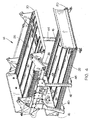
- Fig. 2 is a front perspective view of the invention in its transport position, as seen from the left side thereof, with the upper deck in its raised position;
- Fig. 3 is a front perspective view of the invention in its transport position, as seen from the right side thereof, with the upper deck in its raised position;
- Fig. 4 is a rear perspective view of the invention in its transport position, as seen from the left side thereof, with the upper deck in its raised position;
- Fig. 5 is a view similar to Fig. 4 except that the ramp at the rearward end of the lower deck is in its loading-unloading position;
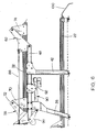
- Fig. 6 is a left side view of the invention in the position of Fig. 5;
- Fig. 7 is a left rear perspective view of the invention with the upper deck in its lowered loading-unloading position;
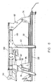
- Fig. 8 is a left side view of the invention in the position of Fig. 7; and
- Fig. 9 is a partial rear perspective view of the vehicle and the apparatus of this invention.
- The
numeral 10 refers generally to a small van or vehicle such as a Mercedes Vito or Vauxhall Vivaro, each of which may have varying wheelbases. Van 10 includes acargo compartment 12 therein. Normally, wheel housings 13 extend into thecompartment 12. Thenumeral 14 refers to the casket transporting apparatus of this invention. Although theapparatus 14 is ideally suited to transport caskets, it may be used to transport other death care items such as cots, stretchers, cremation trays or the like. -
Apparatus 14 includes alower deck 16 having aforward end 18,rear end 20, andopposite sides Apparatus 14 also includes anupper deck 26 having aforward end 28, rearwardend 30, andopposite sides - The
numerals frame member 40 secured to the lower ends thereof and extending therebetween. Normally,frame member 40 will be secured to the floor of the vehicle. Thenumerals frame member 46 secured to and extending between the lower ends thereof. Normally,frame member 46 will be secured to the floor of the vehicle. Thenumerals supports support 36 is bolted toside beam 48 rearwardly of the forward end thereof, as illustrated in Fig. 4. The upper end ofsupport 42 is longitudinally selectively adjustably secured to theside frame 48 by the damping assembly referred to generally by the reference numeral 52 (Fig. 4). As seen in Fig. 3, the upper end ofsupport 38 is bolted toside frame 50 rearwardly of the forward end thereof. The upper end ofsupport 44 is selectively longitudinally adjustably secured to theside frame 50 by the clampingassembly 54.Hanger bracket assemblies bolts beam 60 secured thereto and extending therebetween (Fig. 2).Hanger bracket assemblies bolts - One end of
hanger bracket 56 is pivotally connected to an upstanding plate orbracket 70, which is secured toside 32 ofupper deck 26 rearwardly of the forward end thereof by means of a pivot pin orbolt 72. Plate orbracket 74 is secured toside 32 ofupper deck 26 with thehanger bracket assembly 62 being pivotally secured thereto by means of pin orbolt 76. Connecting rod 78 is pivotally connected to and extends between thehanger brackets - Plates or
brackets side 34 ofupper deck 26 and have thehanger bracket assemblies bolts rod 88 is pivotally secured and extends betweenhanger bracket assemblies - The numeral 90 refers to an elongated actuator which is preferably driven by a 12-volt motor or the like and which includes a
body 92 and an extendible andretractable actuator shaft 94.Actuator 90 may be a hydraulic cylinder if so desired. As seen in Figs. 2 and 7,body 92 is longitudinally adjustably and pivotally secured toside frame 48. The end of theactuator shaft 94 is pivotally secured to plate orbracket 96 bybolt 98.Plate 96 forms a part of thehanger bracket assembly 56 so that pivotal movement ofplate 96 causes pivotal movement ofhanger bracket assembly 56. - A
ramp 100 is pivotally connected to the rear end oflower deck 16 and is selectively movable from the transport position of Figs. 2-4 to the loading-unloading position of Figs. 5-8.Decks front walls - In operation, the
apparatus 14 is placed in the cargo area of thesmall van 10 or the like. Depending upon the position of the wheel housings, thesupports supports body 92 ofactuator 90, thehanger bracket assemblies actuator shaft 94 into thebody 92 of thecargo compartment 12 which projects intoactuator 90 causes thehanger bracket assemblies upper deck 26 to its upper position of Figs. 2-5. - As can be seen, the
upper deck 26 is raised and lowered by asingle actuator 90. Preferably, the main system framework is comprised of a steel material while the frames for the decks are aluminum. As stated, thesupports - Thus it can be seen that the invention accomplishes at least all of its stated objectives.
Claims (7)
- A transporting apparatus in combination with a vehicle having an interior compartment above a floor, the vehicle having rearward and forward ends and a door at the rearward end thereof to permit selective access to the interior compartment, the transporting apparatus comprising:a generally horizontally disposed lower support deck having a forward end, a rearward end, and first and second sides;
first and second upstanding supports, having upper and lower ends, positioned outwardly of said first and second sides of said lower deck, respectively, at said forward end of said lower deck;
third and fourth upstanding supports, having upper and lower ends positioned outwardly of said first and second sides of said lower deck, respectively, forwardly of said rearward end of said lower deck;
a first side frame having forward and rearward ends, mounted on said first and third supports at said upper ends thereof, said forward end of said first side frame being positioned forwardly of said upper end of said first support and said rearward end of said first side frame being positioned rearwardly of said upper end of said third support;
a second side frame, having forward and rearward ends, mounted on said second and fourth supports at said upper ends thereof, said forward end of said second side frame positioned forwardly of said upper end of said second support and said rearward end of said second side frame being positioned rearwardly of said upper end of said fourth support;a generally horizontally disposed upper support deck having a forward end, a rearward end, and first and second sides;
said upper deck being movably positioned above said lower deck between said first, second, third and fourth supports;
said upper deck being selectively movable between a lower position and an upper position;
said upper deck being spaced above said lower deck when in its upper position and being positioned adjacent said lower deck when in its lower position;a first hanger bracket assembly pivotally connected to said first side frame at said forward end thereof and pivotally connected to said first side of said upper deck at said forward end thereof;a second hanger bracket assembly pivotally connected to said second side frame at said forward end thereof and pivotally connected to said second side of said upper deck;a third hanger bracket assembly pivotally connected to said first side frame at said rearward end thereof and pivotally connected to said first side of said upper deck;a fourth hanger bracket assembly pivotally connected to said second side frame at said rearward end thereof and pivotally connected to said second side of said upper deck;a first connecting rod pivotally connected to and extending between said first and third hanger bracket assemblies;a second connecting rod pivotally secured to and extending between said second and fourth hanger bracket assemblies;an elongated actuator comprising a body portion and an actuator shaft movably extending therefrom, said actuator shaft being movable between a retracted position and an extended position, said body portion being operably secured to said first side frame and said actuator shaft being operably secured to said first hanger bracket assembly;said first and second hanger bracket assemblies being operably interconnected so that pivotal movement of said first hanger assembly by said actuator causes said second hanger bracket assembly to pivotally move therewith;said upper deck being in its upper position when said actuator shaft is in its retracted position and said upper deck being in its lower position when said actuator shaft is in its extended position. - The combination of claim 1, wherein said third and fourth supports are selectively, longitudinally adjustably secured to said first and second side frames, respectively.
- The combination of claim 1, wherein said upper deck has first, second, third and fourth upstanding brackets, each having upper and lower ends, said first bracket being secured to said first side of said upper deck adjacent said forward end thereof; said second bracket being secured to said second side of said upper deck adjacent said forward end thereof; said third bracket being secured to said first side of said upper deck adjacent said rearward end thereof and said fourth bracket being secured to said second side of said upper deck adjacent said rearward and thereof; wherein said first, second, third and fourth hanger brackets are pivotally secured to said upper ends of said first, second, third and fourth brackets, respectively.
- The combination of claim 1, wherein said actuator is selectively, longitudinally adjustably secured to said first side frame.
- The combination of claim 1, wherein a first frame member is secured to and extends between said lower ends of said first and second supports beneath said lower deck and wherein a second frame member is secured to and extends between said lower ends of said third and fourth supports beneath said lower deck.
- The combination of claim 5, wherein said first and second frame members are can be secured to the floor of the vehicle.
- The combination of claim 1, wherein a pair of wheel housings extend into the interior compartment of the vehicle and wherein said third and fourth supports are positioned forwardly of said wheel housings.
Applications Claiming Priority (1)
| Application Number | Priority Date | Filing Date | Title |
|---|---|---|---|
| US11/041,716 US7014237B1 (en) | 2005-01-24 | 2005-01-24 | Casket transporting apparatus |
Publications (2)
| Publication Number | Publication Date |
|---|---|
| EP1683504A1 true EP1683504A1 (en) | 2006-07-26 |
| EP1683504B1 EP1683504B1 (en) | 2008-05-28 |
Family
ID=36045419
Family Applications (1)
| Application Number | Title | Priority Date | Filing Date |
|---|---|---|---|
| EP06000138A Expired - Lifetime EP1683504B1 (en) | 2005-01-24 | 2006-01-04 | Casket transporting apparatus |
Country Status (4)
| Country | Link |
|---|---|
| US (1) | US7014237B1 (en) |
| EP (1) | EP1683504B1 (en) |
| AT (1) | ATE396685T1 (en) |
| DE (1) | DE602006001300D1 (en) |
Cited By (1)
| Publication number | Priority date | Publication date | Assignee | Title |
|---|---|---|---|---|
| DE202009009797U1 (en) * | 2009-07-17 | 2010-09-16 | Ramspeck, Rolf | hearse |
Families Citing this family (9)
| Publication number | Priority date | Publication date | Assignee | Title |
|---|---|---|---|---|
| US20100327177A1 (en) * | 2009-06-25 | 2010-12-30 | Scott Michael Flynn | Casket carrier device |
| US8398137B2 (en) * | 2010-12-27 | 2013-03-19 | GM Global Technology Operations LLC | Auxiliary bed floor for sheet materials |
| US8905454B2 (en) | 2011-05-06 | 2014-12-09 | Fyda Freightliner Cincinnati, Inc. | Casket handling system |
| US10035464B2 (en) | 2016-08-26 | 2018-07-31 | Toyota Motor Engineering & Manufacturing North America, Inc. | Multi-level rear storage systems and methods for vehicles |
| EP3339067B1 (en) | 2016-12-23 | 2022-01-26 | Link MFG., Ltd. | Commercial vehicle with a cab and a cab suspension |
| US10329087B2 (en) * | 2017-06-29 | 2019-06-25 | Stonebrooke Equipment, Inc. | Transport carrier with enhanced loading/unloading |
| US10967927B2 (en) | 2017-09-22 | 2021-04-06 | Link Mfg., Ltd. | Mounting brackets for auxiliary suspension systems |
| USD1003763S1 (en) * | 2018-11-13 | 2023-11-07 | Baue D Paul | Military hearse |
| WO2023283464A1 (en) | 2021-07-08 | 2023-01-12 | Link Mfg., Ltd. | Driven lift axles and associated systems and methods |
Citations (4)
| Publication number | Priority date | Publication date | Assignee | Title |
|---|---|---|---|---|
| US4029223A (en) * | 1975-07-25 | 1977-06-14 | Mb Associates | Bus loader |
| US4270630A (en) * | 1977-11-28 | 1981-06-02 | Collins Industries, Inc. | Automatic lift assembly |
| US5632357A (en) * | 1992-06-24 | 1997-05-27 | Matre; Vigbjorn | Combined stairs and person hoist |
| US6758648B1 (en) | 2002-06-17 | 2004-07-06 | Link Mfg., Ltd. | Deathcare apparatus for transporting multiple caskets, cots, stretchers, cremation trays or the like |
Family Cites Families (8)
| Publication number | Priority date | Publication date | Assignee | Title |
|---|---|---|---|---|
| US1925964A (en) * | 1932-05-14 | 1933-09-05 | Koppe William | Adjustable casket table for automobile hearses |
| ZA859080B (en) * | 1984-11-29 | 1986-08-27 | Hynbrood Pty Ltd | Trolley carrier |
| FR2635301B1 (en) * | 1988-08-05 | 1990-10-26 | Lohr Ind | ARTICULATED CONVEYOR CAR CARRIERS WITH MOBILE INDIVIDUAL CARRIERS IN COMPOUND MOVEMENTS |
| US5328320A (en) * | 1991-11-22 | 1994-07-12 | J. Thomas Farrow | Apparatus for lifting a heavy load with respect to the bed of a truck |
| US5567111A (en) * | 1993-12-28 | 1996-10-22 | G & G Intellectual Properties, Inc. | Method for handling and transporting wheeled vehicles |
| SE510639C2 (en) * | 1997-10-17 | 1999-06-14 | Edmolift Ab | Lifting device with lifting and tilting platform |
| US6450742B1 (en) * | 2000-12-21 | 2002-09-17 | John M. Jenkins | Loading and unloading device transporting vehicles |
| US6932401B1 (en) * | 2004-10-11 | 2005-08-23 | Link Mfg., Ltd. | Casket transporting apparatus |
-
2005
- 2005-01-24 US US11/041,716 patent/US7014237B1/en not_active Expired - Lifetime
-
2006
- 2006-01-04 EP EP06000138A patent/EP1683504B1/en not_active Expired - Lifetime
- 2006-01-04 AT AT06000138T patent/ATE396685T1/en not_active IP Right Cessation
- 2006-01-04 DE DE602006001300T patent/DE602006001300D1/en not_active Expired - Fee Related
Patent Citations (4)
| Publication number | Priority date | Publication date | Assignee | Title |
|---|---|---|---|---|
| US4029223A (en) * | 1975-07-25 | 1977-06-14 | Mb Associates | Bus loader |
| US4270630A (en) * | 1977-11-28 | 1981-06-02 | Collins Industries, Inc. | Automatic lift assembly |
| US5632357A (en) * | 1992-06-24 | 1997-05-27 | Matre; Vigbjorn | Combined stairs and person hoist |
| US6758648B1 (en) | 2002-06-17 | 2004-07-06 | Link Mfg., Ltd. | Deathcare apparatus for transporting multiple caskets, cots, stretchers, cremation trays or the like |
Cited By (1)
| Publication number | Priority date | Publication date | Assignee | Title |
|---|---|---|---|---|
| DE202009009797U1 (en) * | 2009-07-17 | 2010-09-16 | Ramspeck, Rolf | hearse |
Also Published As
| Publication number | Publication date |
|---|---|
| DE602006001300D1 (en) | 2008-07-10 |
| ATE396685T1 (en) | 2008-06-15 |
| US7014237B1 (en) | 2006-03-21 |
| EP1683504B1 (en) | 2008-05-28 |
Similar Documents
| Publication | Publication Date | Title |
|---|---|---|
| US5035462A (en) | Utility vehicle chassis having a vertically adjustable bed | |
| US6024528A (en) | Ambulance mounted stretcher lift | |
| US7802816B2 (en) | Control arm support brackets and vehicles using same | |
| US6598922B2 (en) | Pickup truck bed extender apparatus | |
| US10988189B2 (en) | Extendable trailer for freight containers | |
| US7014237B1 (en) | Casket transporting apparatus | |
| EP0997327A2 (en) | Suspension for vehicle with vertically adjustable loading bed | |
| US6234502B1 (en) | Trailing arm leaf spring wheel suspension | |
| WO2003000519A1 (en) | Combination pickup truck liftgate/tailgate | |
| US4750855A (en) | Retrofittable vehicle framework means and method for interchangeable use with a variety of attachment units | |
| DE10017570A1 (en) | Pick-up truck; has loading module adjustably held on truck chassis that can be moved between position behind loading board and forwards position just behind cab | |
| US6932401B1 (en) | Casket transporting apparatus | |
| CA3049998C (en) | Low profile trolley for a tow saddle | |
| US20020195794A1 (en) | Trailer accessible from each end and method | |
| US6758648B1 (en) | Deathcare apparatus for transporting multiple caskets, cots, stretchers, cremation trays or the like | |
| BE1008971A3 (en) | CHARGING EQUIPMENT FOR VEHICLES AND VEHICLES EQUIPPED WITH THIS. | |
| US5462301A (en) | Means for mounting an air powered actuator for retracting the locking pins of a slider | |
| US8740249B1 (en) | Combine header transport trailer | |
| CA2926422C (en) | Self-deploying service step | |
| US3255995A (en) | Landing gear structure | |
| EP0128807A1 (en) | Vehicle lifting and towing apparatus | |
| US8118368B1 (en) | Saddle assembly for a side-dump trailer or truck | |
| US20190291624A1 (en) | Hydraulic truck bed lifting apparatus and method | |
| WO1999015124A1 (en) | Vehicle with lift bed | |
| US7651312B2 (en) | Truck with tilting deck |
Legal Events
| Date | Code | Title | Description |
|---|---|---|---|
| PUAI | Public reference made under article 153(3) epc to a published international application that has entered the european phase |
Free format text: ORIGINAL CODE: 0009012 |
|
| AK | Designated contracting states |
Kind code of ref document: A1 Designated state(s): AT BE BG CH CY CZ DE DK EE ES FI FR GB GR HU IE IS IT LI LT LU LV MC NL PL PT RO SE SI SK TR |
|
| AX | Request for extension of the european patent |
Extension state: AL BA HR MK YU |
|
| 17P | Request for examination filed |
Effective date: 20060925 |
|
| 17Q | First examination report despatched |
Effective date: 20061109 |
|
| AKX | Designation fees paid |
Designated state(s): AT BE BG CH CY CZ DE DK EE ES FI FR GB GR HU IE IS IT LI LT LU LV MC NL PL PT RO SE SI SK TR |
|
| GRAP | Despatch of communication of intention to grant a patent |
Free format text: ORIGINAL CODE: EPIDOSNIGR1 |
|
| GRAS | Grant fee paid |
Free format text: ORIGINAL CODE: EPIDOSNIGR3 |
|
| GRAA | (expected) grant |
Free format text: ORIGINAL CODE: 0009210 |
|
| AK | Designated contracting states |
Kind code of ref document: B1 Designated state(s): AT BE BG CH CY CZ DE DK EE ES FI FR GB GR HU IE IS IT LI LT LU LV MC NL PL PT RO SE SI SK TR |
|
| REG | Reference to a national code |
Ref country code: GB Ref legal event code: FG4D |
|
| REG | Reference to a national code |
Ref country code: CH Ref legal event code: EP |
|
| REF | Corresponds to: |
Ref document number: 602006001300 Country of ref document: DE Date of ref document: 20080710 Kind code of ref document: P |
|
| REG | Reference to a national code |
Ref country code: IE Ref legal event code: FG4D |
|
| PG25 | Lapsed in a contracting state [announced via postgrant information from national office to epo] |
Ref country code: SI Free format text: LAPSE BECAUSE OF FAILURE TO SUBMIT A TRANSLATION OF THE DESCRIPTION OR TO PAY THE FEE WITHIN THE PRESCRIBED TIME-LIMIT Effective date: 20080528 |
|
| PG25 | Lapsed in a contracting state [announced via postgrant information from national office to epo] |
Ref country code: FI Free format text: LAPSE BECAUSE OF FAILURE TO SUBMIT A TRANSLATION OF THE DESCRIPTION OR TO PAY THE FEE WITHIN THE PRESCRIBED TIME-LIMIT Effective date: 20080528 Ref country code: ES Free format text: LAPSE BECAUSE OF FAILURE TO SUBMIT A TRANSLATION OF THE DESCRIPTION OR TO PAY THE FEE WITHIN THE PRESCRIBED TIME-LIMIT Effective date: 20080908 |
|
| PG25 | Lapsed in a contracting state [announced via postgrant information from national office to epo] |
Ref country code: LV Free format text: LAPSE BECAUSE OF FAILURE TO SUBMIT A TRANSLATION OF THE DESCRIPTION OR TO PAY THE FEE WITHIN THE PRESCRIBED TIME-LIMIT Effective date: 20080528 Ref country code: NL Free format text: LAPSE BECAUSE OF FAILURE TO SUBMIT A TRANSLATION OF THE DESCRIPTION OR TO PAY THE FEE WITHIN THE PRESCRIBED TIME-LIMIT Effective date: 20080528 Ref country code: AT Free format text: LAPSE BECAUSE OF FAILURE TO SUBMIT A TRANSLATION OF THE DESCRIPTION OR TO PAY THE FEE WITHIN THE PRESCRIBED TIME-LIMIT Effective date: 20080528 |
|
| NLV1 | Nl: lapsed or annulled due to failure to fulfill the requirements of art. 29p and 29m of the patents act | ||
| PG25 | Lapsed in a contracting state [announced via postgrant information from national office to epo] |
Ref country code: IS Free format text: LAPSE BECAUSE OF FAILURE TO SUBMIT A TRANSLATION OF THE DESCRIPTION OR TO PAY THE FEE WITHIN THE PRESCRIBED TIME-LIMIT Effective date: 20080928 |
|
| PG25 | Lapsed in a contracting state [announced via postgrant information from national office to epo] |
Ref country code: DK Free format text: LAPSE BECAUSE OF FAILURE TO SUBMIT A TRANSLATION OF THE DESCRIPTION OR TO PAY THE FEE WITHIN THE PRESCRIBED TIME-LIMIT Effective date: 20080528 Ref country code: CZ Free format text: LAPSE BECAUSE OF FAILURE TO SUBMIT A TRANSLATION OF THE DESCRIPTION OR TO PAY THE FEE WITHIN THE PRESCRIBED TIME-LIMIT Effective date: 20080528 Ref country code: LT Free format text: LAPSE BECAUSE OF FAILURE TO SUBMIT A TRANSLATION OF THE DESCRIPTION OR TO PAY THE FEE WITHIN THE PRESCRIBED TIME-LIMIT Effective date: 20080528 Ref country code: SE Free format text: LAPSE BECAUSE OF FAILURE TO SUBMIT A TRANSLATION OF THE DESCRIPTION OR TO PAY THE FEE WITHIN THE PRESCRIBED TIME-LIMIT Effective date: 20080828 |
|
| PG25 | Lapsed in a contracting state [announced via postgrant information from national office to epo] |
Ref country code: SK Free format text: LAPSE BECAUSE OF FAILURE TO SUBMIT A TRANSLATION OF THE DESCRIPTION OR TO PAY THE FEE WITHIN THE PRESCRIBED TIME-LIMIT Effective date: 20080528 Ref country code: RO Free format text: LAPSE BECAUSE OF FAILURE TO SUBMIT A TRANSLATION OF THE DESCRIPTION OR TO PAY THE FEE WITHIN THE PRESCRIBED TIME-LIMIT Effective date: 20080528 Ref country code: PT Free format text: LAPSE BECAUSE OF FAILURE TO SUBMIT A TRANSLATION OF THE DESCRIPTION OR TO PAY THE FEE WITHIN THE PRESCRIBED TIME-LIMIT Effective date: 20081028 Ref country code: BE Free format text: LAPSE BECAUSE OF FAILURE TO SUBMIT A TRANSLATION OF THE DESCRIPTION OR TO PAY THE FEE WITHIN THE PRESCRIBED TIME-LIMIT Effective date: 20080528 |
|
| PLBE | No opposition filed within time limit |
Free format text: ORIGINAL CODE: 0009261 |
|
| STAA | Information on the status of an ep patent application or granted ep patent |
Free format text: STATUS: NO OPPOSITION FILED WITHIN TIME LIMIT |
|
| PG25 | Lapsed in a contracting state [announced via postgrant information from national office to epo] |
Ref country code: EE Free format text: LAPSE BECAUSE OF FAILURE TO SUBMIT A TRANSLATION OF THE DESCRIPTION OR TO PAY THE FEE WITHIN THE PRESCRIBED TIME-LIMIT Effective date: 20080528 Ref country code: BG Free format text: LAPSE BECAUSE OF FAILURE TO SUBMIT A TRANSLATION OF THE DESCRIPTION OR TO PAY THE FEE WITHIN THE PRESCRIBED TIME-LIMIT Effective date: 20080828 |
|
| 26N | No opposition filed |
Effective date: 20090303 |
|
| PG25 | Lapsed in a contracting state [announced via postgrant information from national office to epo] |
Ref country code: IT Free format text: LAPSE BECAUSE OF FAILURE TO SUBMIT A TRANSLATION OF THE DESCRIPTION OR TO PAY THE FEE WITHIN THE PRESCRIBED TIME-LIMIT Effective date: 20080528 Ref country code: MC Free format text: LAPSE BECAUSE OF NON-PAYMENT OF DUE FEES Effective date: 20090131 |
|
| REG | Reference to a national code |
Ref country code: IE Ref legal event code: MM4A |
|
| PG25 | Lapsed in a contracting state [announced via postgrant information from national office to epo] |
Ref country code: DE Free format text: LAPSE BECAUSE OF NON-PAYMENT OF DUE FEES Effective date: 20090801 |
|
| REG | Reference to a national code |
Ref country code: FR Ref legal event code: ST Effective date: 20091030 |
|
| PG25 | Lapsed in a contracting state [announced via postgrant information from national office to epo] |
Ref country code: IE Free format text: LAPSE BECAUSE OF NON-PAYMENT OF DUE FEES Effective date: 20090104 |
|
| PG25 | Lapsed in a contracting state [announced via postgrant information from national office to epo] |
Ref country code: FR Free format text: LAPSE BECAUSE OF NON-PAYMENT OF DUE FEES Effective date: 20090202 |
|
| PG25 | Lapsed in a contracting state [announced via postgrant information from national office to epo] |
Ref country code: PL Free format text: LAPSE BECAUSE OF FAILURE TO SUBMIT A TRANSLATION OF THE DESCRIPTION OR TO PAY THE FEE WITHIN THE PRESCRIBED TIME-LIMIT Effective date: 20080528 |
|
| REG | Reference to a national code |
Ref country code: CH Ref legal event code: PL |
|
| PG25 | Lapsed in a contracting state [announced via postgrant information from national office to epo] |
Ref country code: LI Free format text: LAPSE BECAUSE OF NON-PAYMENT OF DUE FEES Effective date: 20100131 Ref country code: GR Free format text: LAPSE BECAUSE OF FAILURE TO SUBMIT A TRANSLATION OF THE DESCRIPTION OR TO PAY THE FEE WITHIN THE PRESCRIBED TIME-LIMIT Effective date: 20080829 Ref country code: CH Free format text: LAPSE BECAUSE OF NON-PAYMENT OF DUE FEES Effective date: 20100131 |
|
| PG25 | Lapsed in a contracting state [announced via postgrant information from national office to epo] |
Ref country code: LU Free format text: LAPSE BECAUSE OF NON-PAYMENT OF DUE FEES Effective date: 20090104 |
|
| PG25 | Lapsed in a contracting state [announced via postgrant information from national office to epo] |
Ref country code: HU Free format text: LAPSE BECAUSE OF FAILURE TO SUBMIT A TRANSLATION OF THE DESCRIPTION OR TO PAY THE FEE WITHIN THE PRESCRIBED TIME-LIMIT Effective date: 20081129 |
|
| PG25 | Lapsed in a contracting state [announced via postgrant information from national office to epo] |
Ref country code: TR Free format text: LAPSE BECAUSE OF FAILURE TO SUBMIT A TRANSLATION OF THE DESCRIPTION OR TO PAY THE FEE WITHIN THE PRESCRIBED TIME-LIMIT Effective date: 20080528 |
|
| PG25 | Lapsed in a contracting state [announced via postgrant information from national office to epo] |
Ref country code: CY Free format text: LAPSE BECAUSE OF FAILURE TO SUBMIT A TRANSLATION OF THE DESCRIPTION OR TO PAY THE FEE WITHIN THE PRESCRIBED TIME-LIMIT Effective date: 20080528 |
|
| PGFP | Annual fee paid to national office [announced via postgrant information from national office to epo] |
Ref country code: GB Payment date: 20241114 Year of fee payment: 20 |
|
| REG | Reference to a national code |
Ref country code: GB Ref legal event code: PE20 Expiry date: 20260103 |