EP1682048B1 - Implantable valvular prosthesis - Google Patents
Implantable valvular prosthesis Download PDFInfo
- Publication number
- EP1682048B1 EP1682048B1 EP04818596A EP04818596A EP1682048B1 EP 1682048 B1 EP1682048 B1 EP 1682048B1 EP 04818596 A EP04818596 A EP 04818596A EP 04818596 A EP04818596 A EP 04818596A EP 1682048 B1 EP1682048 B1 EP 1682048B1
- Authority
- EP
- European Patent Office
- Prior art keywords
- prosthetic valve
- valve
- membrane assembly
- structural frame
- cantilever
- Prior art date
- Legal status (The legal status is an assumption and is not a legal conclusion. Google has not performed a legal analysis and makes no representation as to the accuracy of the status listed.)
- Expired - Lifetime
Links
- 239000012528 membrane Substances 0.000 claims abstract description 117
- 239000000463 material Substances 0.000 claims description 29
- 229920000642 polymer Polymers 0.000 claims description 23
- 238000000576 coating method Methods 0.000 claims description 22
- 239000011248 coating agent Substances 0.000 claims description 17
- 239000003795 chemical substances by application Substances 0.000 claims description 16
- 239000000835 fiber Substances 0.000 claims description 10
- 210000003462 vein Anatomy 0.000 claims description 10
- 239000003814 drug Substances 0.000 claims description 6
- 229920002994 synthetic fiber Polymers 0.000 claims description 6
- 239000010935 stainless steel Substances 0.000 claims description 5
- 229910001220 stainless steel Inorganic materials 0.000 claims description 5
- 239000012620 biological material Substances 0.000 claims description 3
- 229910001000 nickel titanium Inorganic materials 0.000 claims description 3
- 230000002787 reinforcement Effects 0.000 claims description 3
- 229910000531 Co alloy Inorganic materials 0.000 claims description 2
- 229910001257 Nb alloy Inorganic materials 0.000 claims description 2
- 229910001260 Pt alloy Inorganic materials 0.000 claims description 2
- 229910052715 tantalum Inorganic materials 0.000 claims description 2
- GUVRBAGPIYLISA-UHFFFAOYSA-N tantalum atom Chemical compound [Ta] GUVRBAGPIYLISA-UHFFFAOYSA-N 0.000 claims description 2
- 229940124597 therapeutic agent Drugs 0.000 claims 3
- 210000004379 membrane Anatomy 0.000 description 105
- 210000002073 venous valve Anatomy 0.000 description 41
- 238000000034 method Methods 0.000 description 19
- 230000017531 blood circulation Effects 0.000 description 15
- BQCIDUSAKPWEOX-UHFFFAOYSA-N 1,1-Difluoroethene Chemical compound FC(F)=C BQCIDUSAKPWEOX-UHFFFAOYSA-N 0.000 description 10
- 229920000295 expanded polytetrafluoroethylene Polymers 0.000 description 9
- 239000012530 fluid Substances 0.000 description 9
- 210000002216 heart Anatomy 0.000 description 9
- 239000008280 blood Substances 0.000 description 8
- 210000004369 blood Anatomy 0.000 description 8
- 230000007246 mechanism Effects 0.000 description 8
- 210000003709 heart valve Anatomy 0.000 description 7
- OKKJLVBELUTLKV-UHFFFAOYSA-N Methanol Chemical compound OC OKKJLVBELUTLKV-UHFFFAOYSA-N 0.000 description 6
- 230000002792 vascular Effects 0.000 description 6
- 229920002635 polyurethane Polymers 0.000 description 5
- 239000004814 polyurethane Substances 0.000 description 5
- 238000003466 welding Methods 0.000 description 5
- RJURFGZVJUQBHK-UHFFFAOYSA-N actinomycin D Natural products CC1OC(=O)C(C(C)C)N(C)C(=O)CN(C)C(=O)C2CCCN2C(=O)C(C(C)C)NC(=O)C1NC(=O)C1=C(N)C(=O)C(C)=C2OC(C(C)=CC=C3C(=O)NC4C(=O)NC(C(N5CCCC5C(=O)N(C)CC(=O)N(C)C(C(C)C)C(=O)OC4C)=O)C(C)C)=C3N=C21 RJURFGZVJUQBHK-UHFFFAOYSA-N 0.000 description 4
- 238000004873 anchoring Methods 0.000 description 4
- 239000000560 biocompatible material Substances 0.000 description 4
- 210000004027 cell Anatomy 0.000 description 4
- 239000006260 foam Substances 0.000 description 4
- 239000003112 inhibitor Substances 0.000 description 4
- 238000004519 manufacturing process Methods 0.000 description 4
- -1 poly(trimethylenecarbonate) Polymers 0.000 description 4
- 229920001610 polycaprolactone Polymers 0.000 description 4
- 230000008569 process Effects 0.000 description 4
- 239000007787 solid Substances 0.000 description 4
- 239000002904 solvent Substances 0.000 description 4
- 238000011144 upstream manufacturing Methods 0.000 description 4
- DCXYFEDJOCDNAF-REOHCLBHSA-N L-asparagine Chemical compound OC(=O)[C@@H](N)CC(N)=O DCXYFEDJOCDNAF-REOHCLBHSA-N 0.000 description 3
- 229920000954 Polyglycolide Polymers 0.000 description 3
- 230000001028 anti-proliverative effect Effects 0.000 description 3
- 210000000988 bone and bone Anatomy 0.000 description 3
- 230000008859 change Effects 0.000 description 3
- 208000037265 diseases, disorders, signs and symptoms Diseases 0.000 description 3
- 229940079593 drug Drugs 0.000 description 3
- 229920001973 fluoroelastomer Polymers 0.000 description 3
- 229920002313 fluoropolymer Polymers 0.000 description 3
- 239000004811 fluoropolymer Substances 0.000 description 3
- HCDGVLDPFQMKDK-UHFFFAOYSA-N hexafluoropropylene Chemical group FC(F)=C(F)C(F)(F)F HCDGVLDPFQMKDK-UHFFFAOYSA-N 0.000 description 3
- 239000004632 polycaprolactone Substances 0.000 description 3
- 238000012805 post-processing Methods 0.000 description 3
- 230000001225 therapeutic effect Effects 0.000 description 3
- 238000011282 treatment Methods 0.000 description 3
- BSYNRYMUTXBXSQ-UHFFFAOYSA-N Aspirin Chemical compound CC(=O)OC1=CC=CC=C1C(O)=O BSYNRYMUTXBXSQ-UHFFFAOYSA-N 0.000 description 2
- IJGRMHOSHXDMSA-UHFFFAOYSA-N Atomic nitrogen Chemical compound N#N IJGRMHOSHXDMSA-UHFFFAOYSA-N 0.000 description 2
- DLGOEMSEDOSKAD-UHFFFAOYSA-N Carmustine Chemical compound ClCCNC(=O)N(N=O)CCCl DLGOEMSEDOSKAD-UHFFFAOYSA-N 0.000 description 2
- PTOAARAWEBMLNO-KVQBGUIXSA-N Cladribine Chemical compound C1=NC=2C(N)=NC(Cl)=NC=2N1[C@H]1C[C@H](O)[C@@H](CO)O1 PTOAARAWEBMLNO-KVQBGUIXSA-N 0.000 description 2
- 108010092160 Dactinomycin Proteins 0.000 description 2
- AOJJSUZBOXZQNB-TZSSRYMLSA-N Doxorubicin Chemical compound O([C@H]1C[C@@](O)(CC=2C(O)=C3C(=O)C=4C=CC=C(C=4C(=O)C3=C(O)C=21)OC)C(=O)CO)[C@H]1C[C@H](N)[C@H](O)[C@H](C)O1 AOJJSUZBOXZQNB-TZSSRYMLSA-N 0.000 description 2
- 108050007372 Fibroblast Growth Factor Proteins 0.000 description 2
- 102000018233 Fibroblast Growth Factor Human genes 0.000 description 2
- HTTJABKRGRZYRN-UHFFFAOYSA-N Heparin Chemical compound OC1C(NC(=O)C)C(O)OC(COS(O)(=O)=O)C1OC1C(OS(O)(=O)=O)C(O)C(OC2C(C(OS(O)(=O)=O)C(OC3C(C(O)C(O)C(O3)C(O)=O)OS(O)(=O)=O)C(CO)O2)NS(O)(=O)=O)C(C(O)=O)O1 HTTJABKRGRZYRN-UHFFFAOYSA-N 0.000 description 2
- SIKJAQJRHWYJAI-UHFFFAOYSA-N Indole Chemical compound C1=CC=C2NC=CC2=C1 SIKJAQJRHWYJAI-UHFFFAOYSA-N 0.000 description 2
- 108010073929 Vascular Endothelial Growth Factor A Proteins 0.000 description 2
- 102000005789 Vascular Endothelial Growth Factors Human genes 0.000 description 2
- 108010019530 Vascular Endothelial Growth Factors Proteins 0.000 description 2
- 208000027418 Wounds and injury Diseases 0.000 description 2
- 229960001138 acetylsalicylic acid Drugs 0.000 description 2
- 239000002253 acid Substances 0.000 description 2
- 150000007513 acids Chemical class 0.000 description 2
- RJURFGZVJUQBHK-IIXSONLDSA-N actinomycin D Chemical compound C[C@H]1OC(=O)[C@H](C(C)C)N(C)C(=O)CN(C)C(=O)[C@@H]2CCCN2C(=O)[C@@H](C(C)C)NC(=O)[C@H]1NC(=O)C1=C(N)C(=O)C(C)=C2OC(C(C)=CC=C3C(=O)N[C@@H]4C(=O)N[C@@H](C(N5CCC[C@H]5C(=O)N(C)CC(=O)N(C)[C@@H](C(C)C)C(=O)O[C@@H]4C)=O)C(C)C)=C3N=C21 RJURFGZVJUQBHK-IIXSONLDSA-N 0.000 description 2
- 230000002927 anti-mitotic effect Effects 0.000 description 2
- 229960001230 asparagine Drugs 0.000 description 2
- 230000006835 compression Effects 0.000 description 2
- 238000007906 compression Methods 0.000 description 2
- 238000010276 construction Methods 0.000 description 2
- 230000007797 corrosion Effects 0.000 description 2
- 238000005260 corrosion Methods 0.000 description 2
- 229960000640 dactinomycin Drugs 0.000 description 2
- 238000013461 design Methods 0.000 description 2
- 238000002651 drug therapy Methods 0.000 description 2
- 238000010041 electrostatic spinning Methods 0.000 description 2
- 238000005516 engineering process Methods 0.000 description 2
- 229940088598 enzyme Drugs 0.000 description 2
- 229940126864 fibroblast growth factor Drugs 0.000 description 2
- 239000006261 foam material Substances 0.000 description 2
- JYGXADMDTFJGBT-VWUMJDOOSA-N hydrocortisone Chemical compound O=C1CC[C@]2(C)[C@H]3[C@@H](O)C[C@](C)([C@@](CC4)(O)C(=O)CO)[C@@H]4[C@@H]3CCC2=C1 JYGXADMDTFJGBT-VWUMJDOOSA-N 0.000 description 2
- 239000007943 implant Substances 0.000 description 2
- CGIGDMFJXJATDK-UHFFFAOYSA-N indomethacin Chemical compound CC1=C(CC(O)=O)C2=CC(OC)=CC=C2N1C(=O)C1=CC=C(Cl)C=C1 CGIGDMFJXJATDK-UHFFFAOYSA-N 0.000 description 2
- 210000003141 lower extremity Anatomy 0.000 description 2
- 239000003550 marker Substances 0.000 description 2
- CFCUWKMKBJTWLW-BKHRDMLASA-N mithramycin Chemical compound O([C@@H]1C[C@@H](O[C@H](C)[C@H]1O)OC=1C=C2C=C3C[C@H]([C@@H](C(=O)C3=C(O)C2=C(O)C=1C)O[C@@H]1O[C@H](C)[C@@H](O)[C@H](O[C@@H]2O[C@H](C)[C@H](O)[C@H](O[C@@H]3O[C@H](C)[C@@H](O)[C@@](C)(O)C3)C2)C1)[C@H](OC)C(=O)[C@@H](O)[C@@H](C)O)[C@H]1C[C@@H](O)[C@H](O)[C@@H](C)O1 CFCUWKMKBJTWLW-BKHRDMLASA-N 0.000 description 2
- 239000000203 mixture Substances 0.000 description 2
- 238000012986 modification Methods 0.000 description 2
- 230000004048 modification Effects 0.000 description 2
- 230000002093 peripheral effect Effects 0.000 description 2
- BASFCYQUMIYNBI-UHFFFAOYSA-N platinum Chemical compound [Pt] BASFCYQUMIYNBI-UHFFFAOYSA-N 0.000 description 2
- 229960003171 plicamycin Drugs 0.000 description 2
- 229920000747 poly(lactic acid) Polymers 0.000 description 2
- 229920000162 poly(ureaurethane) Polymers 0.000 description 2
- 239000004633 polyglycolic acid Substances 0.000 description 2
- 239000004626 polylactic acid Substances 0.000 description 2
- 229920001343 polytetrafluoroethylene Polymers 0.000 description 2
- 239000004810 polytetrafluoroethylene Substances 0.000 description 2
- 229920000166 polytrimethylene carbonate Polymers 0.000 description 2
- 239000011148 porous material Substances 0.000 description 2
- ZAHRKKWIAAJSAO-UHFFFAOYSA-N rapamycin Natural products COCC(O)C(=C/C(C)C(=O)CC(OC(=O)C1CCCCN1C(=O)C(=O)C2(O)OC(CC(OC)C(=CC=CC=CC(C)CC(C)C(=O)C)C)CCC2C)C(C)CC3CCC(O)C(C3)OC)C ZAHRKKWIAAJSAO-UHFFFAOYSA-N 0.000 description 2
- 230000008439 repair process Effects 0.000 description 2
- 229960002930 sirolimus Drugs 0.000 description 2
- QFJCIRLUMZQUOT-HPLJOQBZSA-N sirolimus Chemical compound C1C[C@@H](O)[C@H](OC)C[C@@H]1C[C@@H](C)[C@H]1OC(=O)[C@@H]2CCCCN2C(=O)C(=O)[C@](O)(O2)[C@H](C)CC[C@H]2C[C@H](OC)/C(C)=C/C=C/C=C/[C@@H](C)C[C@@H](C)C(=O)[C@H](OC)[C@H](O)/C(C)=C/[C@@H](C)C(=O)C1 QFJCIRLUMZQUOT-HPLJOQBZSA-N 0.000 description 2
- 238000011477 surgical intervention Methods 0.000 description 2
- 238000001356 surgical procedure Methods 0.000 description 2
- BFKJFAAPBSQJPD-UHFFFAOYSA-N tetrafluoroethene Chemical group FC(F)=C(F)F BFKJFAAPBSQJPD-UHFFFAOYSA-N 0.000 description 2
- 229920002725 thermoplastic elastomer Polymers 0.000 description 2
- 230000008719 thickening Effects 0.000 description 2
- WYWHKKSPHMUBEB-UHFFFAOYSA-N tioguanine Chemical compound N1C(N)=NC(=S)C2=C1N=CN2 WYWHKKSPHMUBEB-UHFFFAOYSA-N 0.000 description 2
- 238000002054 transplantation Methods 0.000 description 2
- FPVKHBSQESCIEP-UHFFFAOYSA-N (8S)-3-(2-deoxy-beta-D-erythro-pentofuranosyl)-3,6,7,8-tetrahydroimidazo[4,5-d][1,3]diazepin-8-ol Natural products C1C(O)C(CO)OC1N1C(NC=NCC2O)=C2N=C1 FPVKHBSQESCIEP-UHFFFAOYSA-N 0.000 description 1
- FDKXTQMXEQVLRF-ZHACJKMWSA-N (E)-dacarbazine Chemical compound CN(C)\N=N\c1[nH]cnc1C(N)=O FDKXTQMXEQVLRF-ZHACJKMWSA-N 0.000 description 1
- VPVXHAANQNHFSF-UHFFFAOYSA-N 1,4-dioxan-2-one Chemical compound O=C1COCCO1 VPVXHAANQNHFSF-UHFFFAOYSA-N 0.000 description 1
- 102100025573 1-alkyl-2-acetylglycerophosphocholine esterase Human genes 0.000 description 1
- VSNHCAURESNICA-NJFSPNSNSA-N 1-oxidanylurea Chemical compound N[14C](=O)NO VSNHCAURESNICA-NJFSPNSNSA-N 0.000 description 1
- FUFLCEKSBBHCMO-UHFFFAOYSA-N 11-dehydrocorticosterone Natural products O=C1CCC2(C)C3C(=O)CC(C)(C(CC4)C(=O)CO)C4C3CCC2=C1 FUFLCEKSBBHCMO-UHFFFAOYSA-N 0.000 description 1
- CTRPRMNBTVRDFH-UHFFFAOYSA-N 2-n-methyl-1,3,5-triazine-2,4,6-triamine Chemical class CNC1=NC(N)=NC(N)=N1 CTRPRMNBTVRDFH-UHFFFAOYSA-N 0.000 description 1
- PLIKAWJENQZMHA-UHFFFAOYSA-N 4-aminophenol Chemical class NC1=CC=C(O)C=C1 PLIKAWJENQZMHA-UHFFFAOYSA-N 0.000 description 1
- VHRSUDSXCMQTMA-PJHHCJLFSA-N 6alpha-methylprednisolone Chemical compound C([C@@]12C)=CC(=O)C=C1[C@@H](C)C[C@@H]1[C@@H]2[C@@H](O)C[C@]2(C)[C@@](O)(C(=O)CO)CC[C@H]21 VHRSUDSXCMQTMA-PJHHCJLFSA-N 0.000 description 1
- STQGQHZAVUOBTE-UHFFFAOYSA-N 7-Cyan-hept-2t-en-4,6-diinsaeure Natural products C1=2C(O)=C3C(=O)C=4C(OC)=CC=CC=4C(=O)C3=C(O)C=2CC(O)(C(C)=O)CC1OC1CC(N)C(O)C(C)O1 STQGQHZAVUOBTE-UHFFFAOYSA-N 0.000 description 1
- RZVAJINKPMORJF-UHFFFAOYSA-N Acetaminophen Chemical compound CC(=O)NC1=CC=C(O)C=C1 RZVAJINKPMORJF-UHFFFAOYSA-N 0.000 description 1
- 206010002915 Aortic valve incompetence Diseases 0.000 description 1
- 108010024976 Asparaginase Proteins 0.000 description 1
- DCXYFEDJOCDNAF-UHFFFAOYSA-N Asparagine Natural products OC(=O)C(N)CC(N)=O DCXYFEDJOCDNAF-UHFFFAOYSA-N 0.000 description 1
- XHVAWZZCDCWGBK-WYRLRVFGSA-M Aurothioglucose Chemical compound OC[C@H]1O[C@H](S[Au])[C@H](O)[C@@H](O)[C@@H]1O XHVAWZZCDCWGBK-WYRLRVFGSA-M 0.000 description 1
- NOWKCMXCCJGMRR-UHFFFAOYSA-N Aziridine Chemical class C1CN1 NOWKCMXCCJGMRR-UHFFFAOYSA-N 0.000 description 1
- 239000005552 B01AC04 - Clopidogrel Substances 0.000 description 1
- 239000005528 B01AC05 - Ticlopidine Substances 0.000 description 1
- 108010006654 Bleomycin Proteins 0.000 description 1
- 241000283690 Bos taurus Species 0.000 description 1
- OKTJSMMVPCPJKN-UHFFFAOYSA-N Carbon Chemical compound [C] OKTJSMMVPCPJKN-UHFFFAOYSA-N 0.000 description 1
- 229940123587 Cell cycle inhibitor Drugs 0.000 description 1
- JWBOIMRXGHLCPP-UHFFFAOYSA-N Chloditan Chemical compound C=1C=CC=C(Cl)C=1C(C(Cl)Cl)C1=CC=C(Cl)C=C1 JWBOIMRXGHLCPP-UHFFFAOYSA-N 0.000 description 1
- 206010053567 Coagulopathies Diseases 0.000 description 1
- MFYSYFVPBJMHGN-UHFFFAOYSA-N Cortisone Natural products O=C1CCC2(C)C3C(=O)CC(C)(C(CC4)(O)C(=O)CO)C4C3CCC2=C1 MFYSYFVPBJMHGN-UHFFFAOYSA-N 0.000 description 1
- MFYSYFVPBJMHGN-ZPOLXVRWSA-N Cortisone Chemical compound O=C1CC[C@]2(C)[C@H]3C(=O)C[C@](C)([C@@](CC4)(O)C(=O)CO)[C@@H]4[C@@H]3CCC2=C1 MFYSYFVPBJMHGN-ZPOLXVRWSA-N 0.000 description 1
- 102000016736 Cyclin Human genes 0.000 description 1
- 108050006400 Cyclin Proteins 0.000 description 1
- CMSMOCZEIVJLDB-UHFFFAOYSA-N Cyclophosphamide Chemical compound ClCCN(CCCl)P1(=O)NCCCO1 CMSMOCZEIVJLDB-UHFFFAOYSA-N 0.000 description 1
- PMATZTZNYRCHOR-CGLBZJNRSA-N Cyclosporin A Chemical compound CC[C@@H]1NC(=O)[C@H]([C@H](O)[C@H](C)C\C=C\C)N(C)C(=O)[C@H](C(C)C)N(C)C(=O)[C@H](CC(C)C)N(C)C(=O)[C@H](CC(C)C)N(C)C(=O)[C@@H](C)NC(=O)[C@H](C)NC(=O)[C@H](CC(C)C)N(C)C(=O)[C@H](C(C)C)NC(=O)[C@H](CC(C)C)N(C)C(=O)CN(C)C1=O PMATZTZNYRCHOR-CGLBZJNRSA-N 0.000 description 1
- 108010036949 Cyclosporine Proteins 0.000 description 1
- UHDGCWIWMRVCDJ-CCXZUQQUSA-N Cytarabine Chemical compound O=C1N=C(N)C=CN1[C@H]1[C@@H](O)[C@H](O)[C@@H](CO)O1 UHDGCWIWMRVCDJ-CCXZUQQUSA-N 0.000 description 1
- 108090000790 Enzymes Proteins 0.000 description 1
- 102000004190 Enzymes Human genes 0.000 description 1
- GHASVSINZRGABV-UHFFFAOYSA-N Fluorouracil Chemical compound FC1=CNC(=O)NC1=O GHASVSINZRGABV-UHFFFAOYSA-N 0.000 description 1
- 102000009465 Growth Factor Receptors Human genes 0.000 description 1
- 108010009202 Growth Factor Receptors Proteins 0.000 description 1
- 229940121710 HMGCoA reductase inhibitor Drugs 0.000 description 1
- HEFNNWSXXWATRW-UHFFFAOYSA-N Ibuprofen Chemical compound CC(C)CC1=CC=C(C(C)C(O)=O)C=C1 HEFNNWSXXWATRW-UHFFFAOYSA-N 0.000 description 1
- XDXDZDZNSLXDNA-UHFFFAOYSA-N Idarubicin Natural products C1C(N)C(O)C(C)OC1OC1C2=C(O)C(C(=O)C3=CC=CC=C3C3=O)=C3C(O)=C2CC(O)(C(C)=O)C1 XDXDZDZNSLXDNA-UHFFFAOYSA-N 0.000 description 1
- XDXDZDZNSLXDNA-TZNDIEGXSA-N Idarubicin Chemical compound C1[C@H](N)[C@H](O)[C@H](C)O[C@H]1O[C@@H]1C2=C(O)C(C(=O)C3=CC=CC=C3C3=O)=C3C(O)=C2C[C@@](O)(C(C)=O)C1 XDXDZDZNSLXDNA-TZNDIEGXSA-N 0.000 description 1
- 102100022337 Integrin alpha-V Human genes 0.000 description 1
- 229920008365 Kynar Flex® 2750-01 Polymers 0.000 description 1
- FBOZXECLQNJBKD-ZDUSSCGKSA-N L-methotrexate Chemical compound C=1N=C2N=C(N)N=C(N)C2=NC=1CN(C)C1=CC=C(C(=O)N[C@@H](CCC(O)=O)C(O)=O)C=C1 FBOZXECLQNJBKD-ZDUSSCGKSA-N 0.000 description 1
- SBDNJUWAMKYJOX-UHFFFAOYSA-N Meclofenamic Acid Chemical compound CC1=CC=C(Cl)C(NC=2C(=CC=CC=2)C(O)=O)=C1Cl SBDNJUWAMKYJOX-UHFFFAOYSA-N 0.000 description 1
- 229930192392 Mitomycin Natural products 0.000 description 1
- 208000003430 Mitral Valve Prolapse Diseases 0.000 description 1
- 208000020128 Mitral stenosis Diseases 0.000 description 1
- 206010027727 Mitral valve incompetence Diseases 0.000 description 1
- ZOKXTWBITQBERF-UHFFFAOYSA-N Molybdenum Chemical compound [Mo] ZOKXTWBITQBERF-UHFFFAOYSA-N 0.000 description 1
- NWIBSHFKIJFRCO-WUDYKRTCSA-N Mytomycin Chemical compound C1N2C(C(C(C)=C(N)C3=O)=O)=C3[C@@H](COC(N)=O)[C@@]2(OC)[C@@H]2[C@H]1N2 NWIBSHFKIJFRCO-WUDYKRTCSA-N 0.000 description 1
- BLXXJMDCKKHMKV-UHFFFAOYSA-N Nabumetone Chemical compound C1=C(CCC(C)=O)C=CC2=CC(OC)=CC=C21 BLXXJMDCKKHMKV-UHFFFAOYSA-N 0.000 description 1
- MWUXSHHQAYIFBG-UHFFFAOYSA-N Nitric oxide Chemical class O=[N] MWUXSHHQAYIFBG-UHFFFAOYSA-N 0.000 description 1
- 229930012538 Paclitaxel Natural products 0.000 description 1
- 206010067171 Regurgitation Diseases 0.000 description 1
- 229920006373 Solef Polymers 0.000 description 1
- 108010023197 Streptokinase Proteins 0.000 description 1
- QJJXYPPXXYFBGM-LFZNUXCKSA-N Tacrolimus Chemical compound C1C[C@@H](O)[C@H](OC)C[C@@H]1\C=C(/C)[C@@H]1[C@H](C)[C@@H](O)CC(=O)[C@H](CC=C)/C=C(C)/C[C@H](C)C[C@H](OC)[C@H]([C@H](C[C@H]2C)OC)O[C@@]2(O)C(=O)C(=O)N2CCCC[C@H]2C(=O)O1 QJJXYPPXXYFBGM-LFZNUXCKSA-N 0.000 description 1
- FOCVUCIESVLUNU-UHFFFAOYSA-N Thiotepa Chemical compound C1CN1P(N1CC1)(=S)N1CC1 FOCVUCIESVLUNU-UHFFFAOYSA-N 0.000 description 1
- 108090000190 Thrombin Proteins 0.000 description 1
- 108090000373 Tissue Plasminogen Activator Proteins 0.000 description 1
- 102000003978 Tissue Plasminogen Activator Human genes 0.000 description 1
- 206010044642 Tricuspid valve stenosis Diseases 0.000 description 1
- 108090000435 Urokinase-type plasminogen activator Proteins 0.000 description 1
- 102000003990 Urokinase-type plasminogen activator Human genes 0.000 description 1
- JXLYSJRDGCGARV-WWYNWVTFSA-N Vinblastine Natural products O=C(O[C@H]1[C@](O)(C(=O)OC)[C@@H]2N(C)c3c(cc(c(OC)c3)[C@]3(C(=O)OC)c4[nH]c5c(c4CCN4C[C@](O)(CC)C[C@H](C3)C4)cccc5)[C@@]32[C@H]2[C@@]1(CC)C=CCN2CC3)C JXLYSJRDGCGARV-WWYNWVTFSA-N 0.000 description 1
- 229940122803 Vinca alkaloid Drugs 0.000 description 1
- 108010048673 Vitronectin Receptors Proteins 0.000 description 1
- 229960000446 abciximab Drugs 0.000 description 1
- 235000011054 acetic acid Nutrition 0.000 description 1
- PDODBKYPSUYQGT-UHFFFAOYSA-N acetic acid;1h-indene Chemical class CC(O)=O.C1=CC=C2CC=CC2=C1 PDODBKYPSUYQGT-UHFFFAOYSA-N 0.000 description 1
- 238000007792 addition Methods 0.000 description 1
- 230000001780 adrenocortical effect Effects 0.000 description 1
- 125000000217 alkyl group Chemical group 0.000 description 1
- 229940100198 alkylating agent Drugs 0.000 description 1
- 239000002168 alkylating agent Substances 0.000 description 1
- 229960000473 altretamine Drugs 0.000 description 1
- 229960003437 aminoglutethimide Drugs 0.000 description 1
- ROBVIMPUHSLWNV-UHFFFAOYSA-N aminoglutethimide Chemical compound C=1C=C(N)C=CC=1C1(CC)CCC(=O)NC1=O ROBVIMPUHSLWNV-UHFFFAOYSA-N 0.000 description 1
- 230000002491 angiogenic effect Effects 0.000 description 1
- 239000002333 angiotensin II receptor antagonist Substances 0.000 description 1
- 229940125364 angiotensin receptor blocker Drugs 0.000 description 1
- 229940045799 anthracyclines and related substance Drugs 0.000 description 1
- RWZYAGGXGHYGMB-UHFFFAOYSA-N anthranilic acid Chemical class NC1=CC=CC=C1C(O)=O RWZYAGGXGHYGMB-UHFFFAOYSA-N 0.000 description 1
- 239000003242 anti bacterial agent Substances 0.000 description 1
- 230000003110 anti-inflammatory effect Effects 0.000 description 1
- 230000000340 anti-metabolite Effects 0.000 description 1
- 230000002095 anti-migrative effect Effects 0.000 description 1
- 230000001262 anti-secretory effect Effects 0.000 description 1
- 230000000692 anti-sense effect Effects 0.000 description 1
- 229940088710 antibiotic agent Drugs 0.000 description 1
- 239000003146 anticoagulant agent Substances 0.000 description 1
- 229940127219 anticoagulant drug Drugs 0.000 description 1
- 229940100197 antimetabolite Drugs 0.000 description 1
- 239000002256 antimetabolite Substances 0.000 description 1
- 229940045687 antimetabolites folic acid analogs Drugs 0.000 description 1
- 239000003080 antimitotic agent Substances 0.000 description 1
- 229940127218 antiplatelet drug Drugs 0.000 description 1
- 210000000709 aorta Anatomy 0.000 description 1
- 206010002906 aortic stenosis Diseases 0.000 description 1
- 201000002064 aortic valve insufficiency Diseases 0.000 description 1
- 235000009582 asparagine Nutrition 0.000 description 1
- 230000000712 assembly Effects 0.000 description 1
- 238000000429 assembly Methods 0.000 description 1
- AUJRCFUBUPVWSZ-XTZHGVARSA-M auranofin Chemical compound CCP(CC)(CC)=[Au]S[C@@H]1O[C@H](COC(C)=O)[C@@H](OC(C)=O)[C@H](OC(C)=O)[C@H]1OC(C)=O AUJRCFUBUPVWSZ-XTZHGVARSA-M 0.000 description 1
- 229960005207 auranofin Drugs 0.000 description 1
- 229960001799 aurothioglucose Drugs 0.000 description 1
- VSRXQHXAPYXROS-UHFFFAOYSA-N azanide;cyclobutane-1,1-dicarboxylic acid;platinum(2+) Chemical compound [NH2-].[NH2-].[Pt+2].OC(=O)C1(C(O)=O)CCC1 VSRXQHXAPYXROS-UHFFFAOYSA-N 0.000 description 1
- 229960002170 azathioprine Drugs 0.000 description 1
- LMEKQMALGUDUQG-UHFFFAOYSA-N azathioprine Chemical compound CN1C=NC([N+]([O-])=O)=C1SC1=NC=NC2=C1NC=N2 LMEKQMALGUDUQG-UHFFFAOYSA-N 0.000 description 1
- 230000009286 beneficial effect Effects 0.000 description 1
- 230000008901 benefit Effects 0.000 description 1
- 229960002537 betamethasone Drugs 0.000 description 1
- UREBDLICKHMUKA-DVTGEIKXSA-N betamethasone Chemical compound C1CC2=CC(=O)C=C[C@]2(C)[C@]2(F)[C@@H]1[C@@H]1C[C@H](C)[C@@](C(=O)CO)(O)[C@@]1(C)C[C@@H]2O UREBDLICKHMUKA-DVTGEIKXSA-N 0.000 description 1
- 239000011230 binding agent Substances 0.000 description 1
- OYVAGSVQBOHSSS-UAPAGMARSA-O bleomycin A2 Chemical class N([C@H](C(=O)N[C@H](C)[C@@H](O)[C@H](C)C(=O)N[C@@H]([C@H](O)C)C(=O)NCCC=1SC=C(N=1)C=1SC=C(N=1)C(=O)NCCC[S+](C)C)[C@@H](O[C@H]1[C@H]([C@@H](O)[C@H](O)[C@H](CO)O1)O[C@@H]1[C@H]([C@@H](OC(N)=O)[C@H](O)[C@@H](CO)O1)O)C=1N=CNC=1)C(=O)C1=NC([C@H](CC(N)=O)NC[C@H](N)C(N)=O)=NC(N)=C1C OYVAGSVQBOHSSS-UAPAGMARSA-O 0.000 description 1
- 230000036772 blood pressure Effects 0.000 description 1
- 238000009954 braiding Methods 0.000 description 1
- 229960002092 busulfan Drugs 0.000 description 1
- 229910052799 carbon Inorganic materials 0.000 description 1
- 229960004562 carboplatin Drugs 0.000 description 1
- 210000005242 cardiac chamber Anatomy 0.000 description 1
- 229960005243 carmustine Drugs 0.000 description 1
- 210000003850 cellular structure Anatomy 0.000 description 1
- 229960004630 chlorambucil Drugs 0.000 description 1
- JCKYGMPEJWAADB-UHFFFAOYSA-N chlorambucil Chemical compound OC(=O)CCCC1=CC=C(N(CCCl)CCCl)C=C1 JCKYGMPEJWAADB-UHFFFAOYSA-N 0.000 description 1
- 201000002816 chronic venous insufficiency Diseases 0.000 description 1
- 229960001265 ciclosporin Drugs 0.000 description 1
- 229960004316 cisplatin Drugs 0.000 description 1
- DQLATGHUWYMOKM-UHFFFAOYSA-L cisplatin Chemical compound N[Pt](N)(Cl)Cl DQLATGHUWYMOKM-UHFFFAOYSA-L 0.000 description 1
- 229960002436 cladribine Drugs 0.000 description 1
- 229960003009 clopidogrel Drugs 0.000 description 1
- GKTWGGQPFAXNFI-HNNXBMFYSA-N clopidogrel Chemical compound C1([C@H](N2CC=3C=CSC=3CC2)C(=O)OC)=CC=CC=C1Cl GKTWGGQPFAXNFI-HNNXBMFYSA-N 0.000 description 1
- 230000035602 clotting Effects 0.000 description 1
- 239000011247 coating layer Substances 0.000 description 1
- 238000010924 continuous production Methods 0.000 description 1
- 230000001276 controlling effect Effects 0.000 description 1
- 229920001577 copolymer Polymers 0.000 description 1
- 229960004544 cortisone Drugs 0.000 description 1
- 238000005520 cutting process Methods 0.000 description 1
- 229940043378 cyclin-dependent kinase inhibitor Drugs 0.000 description 1
- 229960004397 cyclophosphamide Drugs 0.000 description 1
- 229930182912 cyclosporin Natural products 0.000 description 1
- 229960000684 cytarabine Drugs 0.000 description 1
- 230000006378 damage Effects 0.000 description 1
- 229960000975 daunorubicin Drugs 0.000 description 1
- STQGQHZAVUOBTE-VGBVRHCVSA-N daunorubicin Chemical compound O([C@H]1C[C@@](O)(CC=2C(O)=C3C(=O)C=4C=CC=C(C=4C(=O)C3=C(O)C=21)OC)C(C)=O)[C@H]1C[C@H](N)[C@H](O)[C@H](C)O1 STQGQHZAVUOBTE-VGBVRHCVSA-N 0.000 description 1
- CFCUWKMKBJTWLW-UHFFFAOYSA-N deoliosyl-3C-alpha-L-digitoxosyl-MTM Natural products CC=1C(O)=C2C(O)=C3C(=O)C(OC4OC(C)C(O)C(OC5OC(C)C(O)C(OC6OC(C)C(O)C(C)(O)C6)C5)C4)C(C(OC)C(=O)C(O)C(C)O)CC3=CC2=CC=1OC(OC(C)C1O)CC1OC1CC(O)C(O)C(C)O1 CFCUWKMKBJTWLW-UHFFFAOYSA-N 0.000 description 1
- 230000001419 dependent effect Effects 0.000 description 1
- 229960003957 dexamethasone Drugs 0.000 description 1
- UREBDLICKHMUKA-CXSFZGCWSA-N dexamethasone Chemical compound C1CC2=CC(=O)C=C[C@]2(C)[C@]2(F)[C@@H]1[C@@H]1C[C@@H](C)[C@@](C(=O)CO)(O)[C@@]1(C)C[C@@H]2O UREBDLICKHMUKA-CXSFZGCWSA-N 0.000 description 1
- 229960001259 diclofenac Drugs 0.000 description 1
- DCOPUUMXTXDBNB-UHFFFAOYSA-N diclofenac Chemical compound OC(=O)CC1=CC=CC=C1NC1=C(Cl)C=CC=C1Cl DCOPUUMXTXDBNB-UHFFFAOYSA-N 0.000 description 1
- 230000010339 dilation Effects 0.000 description 1
- 229960002768 dipyridamole Drugs 0.000 description 1
- IZEKFCXSFNUWAM-UHFFFAOYSA-N dipyridamole Chemical compound C=12N=C(N(CCO)CCO)N=C(N3CCCCC3)C2=NC(N(CCO)CCO)=NC=1N1CCCCC1 IZEKFCXSFNUWAM-UHFFFAOYSA-N 0.000 description 1
- 229940042399 direct acting antivirals protease inhibitors Drugs 0.000 description 1
- 201000010099 disease Diseases 0.000 description 1
- 229960004679 doxorubicin Drugs 0.000 description 1
- 239000000890 drug combination Substances 0.000 description 1
- 230000005489 elastic deformation Effects 0.000 description 1
- 229920001971 elastomer Polymers 0.000 description 1
- 239000000806 elastomer Substances 0.000 description 1
- 210000003238 esophagus Anatomy 0.000 description 1
- 229940011871 estrogen Drugs 0.000 description 1
- 239000000262 estrogen Substances 0.000 description 1
- VJJPUSNTGOMMGY-MRVIYFEKSA-N etoposide Chemical compound COC1=C(O)C(OC)=CC([C@@H]2C3=CC=4OCOC=4C=C3[C@@H](O[C@H]3[C@@H]([C@@H](O)[C@@H]4O[C@H](C)OC[C@H]4O3)O)[C@@H]3[C@@H]2C(OC3)=O)=C1 VJJPUSNTGOMMGY-MRVIYFEKSA-N 0.000 description 1
- 229960005420 etoposide Drugs 0.000 description 1
- 239000003527 fibrinolytic agent Substances 0.000 description 1
- 238000011049 filling Methods 0.000 description 1
- 229960000961 floxuridine Drugs 0.000 description 1
- ODKNJVUHOIMIIZ-RRKCRQDMSA-N floxuridine Chemical compound C1[C@H](O)[C@@H](CO)O[C@H]1N1C(=O)NC(=O)C(F)=C1 ODKNJVUHOIMIIZ-RRKCRQDMSA-N 0.000 description 1
- 229960002011 fludrocortisone Drugs 0.000 description 1
- AAXVEMMRQDVLJB-BULBTXNYSA-N fludrocortisone Chemical compound O=C1CC[C@]2(C)[C@@]3(F)[C@@H](O)C[C@](C)([C@@](CC4)(O)C(=O)CO)[C@@H]4[C@@H]3CCC2=C1 AAXVEMMRQDVLJB-BULBTXNYSA-N 0.000 description 1
- 125000001153 fluoro group Chemical group F* 0.000 description 1
- 229960002949 fluorouracil Drugs 0.000 description 1
- 150000002224 folic acids Chemical class 0.000 description 1
- 150000002344 gold compounds Chemical class 0.000 description 1
- 229940015045 gold sodium thiomalate Drugs 0.000 description 1
- 229960002897 heparin Drugs 0.000 description 1
- 229920000669 heparin Polymers 0.000 description 1
- UUVWYPNAQBNQJQ-UHFFFAOYSA-N hexamethylmelamine Chemical compound CN(C)C1=NC(N(C)C)=NC(N(C)C)=N1 UUVWYPNAQBNQJQ-UHFFFAOYSA-N 0.000 description 1
- 229920001519 homopolymer Polymers 0.000 description 1
- 229940088597 hormone Drugs 0.000 description 1
- 239000005556 hormone Substances 0.000 description 1
- 229960000890 hydrocortisone Drugs 0.000 description 1
- 239000002471 hydroxymethylglutaryl coenzyme A reductase inhibitor Substances 0.000 description 1
- 229960001680 ibuprofen Drugs 0.000 description 1
- 229960000908 idarubicin Drugs 0.000 description 1
- 229940125721 immunosuppressive agent Drugs 0.000 description 1
- 238000002513 implantation Methods 0.000 description 1
- 238000001727 in vivo Methods 0.000 description 1
- PZOUSPYUWWUPPK-UHFFFAOYSA-N indole Natural products CC1=CC=CC2=C1C=CN2 PZOUSPYUWWUPPK-UHFFFAOYSA-N 0.000 description 1
- RKJUIXBNRJVNHR-UHFFFAOYSA-N indolenine Natural products C1=CC=C2CC=NC2=C1 RKJUIXBNRJVNHR-UHFFFAOYSA-N 0.000 description 1
- 229960000905 indomethacin Drugs 0.000 description 1
- 208000014674 injury Diseases 0.000 description 1
- 238000003780 insertion Methods 0.000 description 1
- 230000037431 insertion Effects 0.000 description 1
- 210000000936 intestine Anatomy 0.000 description 1
- 229960004752 ketorolac Drugs 0.000 description 1
- OZWKMVRBQXNZKK-UHFFFAOYSA-N ketorolac Chemical compound OC(=O)C1CCN2C1=CC=C2C(=O)C1=CC=CC=C1 OZWKMVRBQXNZKK-UHFFFAOYSA-N 0.000 description 1
- 229940043355 kinase inhibitor Drugs 0.000 description 1
- 238000009940 knitting Methods 0.000 description 1
- 238000003698 laser cutting Methods 0.000 description 1
- 239000010410 layer Substances 0.000 description 1
- 210000004324 lymphatic system Anatomy 0.000 description 1
- 229940124302 mTOR inhibitor Drugs 0.000 description 1
- 230000036244 malformation Effects 0.000 description 1
- 239000003628 mammalian target of rapamycin inhibitor Substances 0.000 description 1
- 229960004961 mechlorethamine Drugs 0.000 description 1
- HAWPXGHAZFHHAD-UHFFFAOYSA-N mechlorethamine Chemical compound ClCCN(C)CCCl HAWPXGHAZFHHAD-UHFFFAOYSA-N 0.000 description 1
- 229960003803 meclofenamic acid Drugs 0.000 description 1
- 229960003464 mefenamic acid Drugs 0.000 description 1
- HYYBABOKPJLUIN-UHFFFAOYSA-N mefenamic acid Chemical compound CC1=CC=CC(NC=2C(=CC=CC=2)C(O)=O)=C1C HYYBABOKPJLUIN-UHFFFAOYSA-N 0.000 description 1
- 229960001924 melphalan Drugs 0.000 description 1
- SGDBTWWWUNNDEQ-LBPRGKRZSA-N melphalan Chemical compound OC(=O)[C@@H](N)CC1=CC=C(N(CCCl)CCCl)C=C1 SGDBTWWWUNNDEQ-LBPRGKRZSA-N 0.000 description 1
- GLVAUDGFNGKCSF-UHFFFAOYSA-N mercaptopurine Chemical compound S=C1NC=NC2=C1NC=N2 GLVAUDGFNGKCSF-UHFFFAOYSA-N 0.000 description 1
- 229960001428 mercaptopurine Drugs 0.000 description 1
- 239000007769 metal material Substances 0.000 description 1
- 229960000485 methotrexate Drugs 0.000 description 1
- 229960004857 mitomycin Drugs 0.000 description 1
- 229960000350 mitotane Drugs 0.000 description 1
- 229960001156 mitoxantrone Drugs 0.000 description 1
- KKZJGLLVHKMTCM-UHFFFAOYSA-N mitoxantrone Chemical compound O=C1C2=C(O)C=CC(O)=C2C(=O)C2=C1C(NCCNCCO)=CC=C2NCCNCCO KKZJGLLVHKMTCM-UHFFFAOYSA-N 0.000 description 1
- 208000006887 mitral valve stenosis Diseases 0.000 description 1
- 229910052750 molybdenum Inorganic materials 0.000 description 1
- 239000011733 molybdenum Substances 0.000 description 1
- 229960004866 mycophenolate mofetil Drugs 0.000 description 1
- RTGDFNSFWBGLEC-SYZQJQIISA-N mycophenolate mofetil Chemical compound COC1=C(C)C=2COC(=O)C=2C(O)=C1C\C=C(/C)CCC(=O)OCCN1CCOCC1 RTGDFNSFWBGLEC-SYZQJQIISA-N 0.000 description 1
- 229960004270 nabumetone Drugs 0.000 description 1
- 229920005615 natural polymer Polymers 0.000 description 1
- 229930014626 natural product Natural products 0.000 description 1
- HLXZNVUGXRDIFK-UHFFFAOYSA-N nickel titanium Chemical compound [Ti].[Ti].[Ti].[Ti].[Ti].[Ti].[Ti].[Ti].[Ti].[Ti].[Ti].[Ni].[Ni].[Ni].[Ni].[Ni].[Ni].[Ni].[Ni].[Ni].[Ni].[Ni].[Ni].[Ni].[Ni] HLXZNVUGXRDIFK-UHFFFAOYSA-N 0.000 description 1
- 229910052758 niobium Inorganic materials 0.000 description 1
- 239000010955 niobium Substances 0.000 description 1
- GUCVJGMIXFAOAE-UHFFFAOYSA-N niobium atom Chemical compound [Nb] GUCVJGMIXFAOAE-UHFFFAOYSA-N 0.000 description 1
- 239000002840 nitric oxide donor Substances 0.000 description 1
- 229910052757 nitrogen Inorganic materials 0.000 description 1
- 229960001592 paclitaxel Drugs 0.000 description 1
- 229960002340 pentostatin Drugs 0.000 description 1
- FPVKHBSQESCIEP-JQCXWYLXSA-N pentostatin Chemical compound C1[C@H](O)[C@@H](CO)O[C@H]1N1C(N=CNC[C@H]2O)=C2N=C1 FPVKHBSQESCIEP-JQCXWYLXSA-N 0.000 description 1
- 239000000137 peptide hydrolase inhibitor Substances 0.000 description 1
- 210000003516 pericardium Anatomy 0.000 description 1
- 229960002895 phenylbutazone Drugs 0.000 description 1
- VYMDGNCVAMGZFE-UHFFFAOYSA-N phenylbutazonum Chemical compound O=C1C(CCCC)C(=O)N(C=2C=CC=CC=2)N1C1=CC=CC=C1 VYMDGNCVAMGZFE-UHFFFAOYSA-N 0.000 description 1
- 208000001297 phlebitis Diseases 0.000 description 1
- 239000003757 phosphotransferase inhibitor Substances 0.000 description 1
- 238000001259 photo etching Methods 0.000 description 1
- 230000000704 physical effect Effects 0.000 description 1
- 229960002702 piroxicam Drugs 0.000 description 1
- QYSPLQLAKJAUJT-UHFFFAOYSA-N piroxicam Chemical compound OC=1C2=CC=CC=C2S(=O)(=O)N(C)C=1C(=O)NC1=CC=CC=N1 QYSPLQLAKJAUJT-UHFFFAOYSA-N 0.000 description 1
- 239000000106 platelet aggregation inhibitor Substances 0.000 description 1
- 229910052697 platinum Inorganic materials 0.000 description 1
- 229920001245 poly(D,L-lactide-co-caprolactone) Polymers 0.000 description 1
- 229920002463 poly(p-dioxanone) polymer Polymers 0.000 description 1
- 239000000622 polydioxanone Substances 0.000 description 1
- 239000002861 polymer material Substances 0.000 description 1
- 229920001296 polysiloxane Polymers 0.000 description 1
- 238000011176 pooling Methods 0.000 description 1
- 229960005205 prednisolone Drugs 0.000 description 1
- OIGNJSKKLXVSLS-VWUMJDOOSA-N prednisolone Chemical compound O=C1C=C[C@]2(C)[C@H]3[C@@H](O)C[C@](C)([C@@](CC4)(O)C(=O)CO)[C@@H]4[C@@H]3CCC2=C1 OIGNJSKKLXVSLS-VWUMJDOOSA-N 0.000 description 1
- 229960004618 prednisone Drugs 0.000 description 1
- XOFYZVNMUHMLCC-ZPOLXVRWSA-N prednisone Chemical compound O=C1C=C[C@]2(C)[C@H]3C(=O)C[C@](C)([C@@](CC4)(O)C(=O)CO)[C@@H]4[C@@H]3CCC2=C1 XOFYZVNMUHMLCC-ZPOLXVRWSA-N 0.000 description 1
- 229960000624 procarbazine Drugs 0.000 description 1
- CPTBDICYNRMXFX-UHFFFAOYSA-N procarbazine Chemical compound CNNCC1=CC=C(C(=O)NC(C)C)C=C1 CPTBDICYNRMXFX-UHFFFAOYSA-N 0.000 description 1
- 150000003212 purines Chemical class 0.000 description 1
- 150000003230 pyrimidines Chemical class 0.000 description 1
- 230000005855 radiation Effects 0.000 description 1
- 239000002994 raw material Substances 0.000 description 1
- 239000002464 receptor antagonist Substances 0.000 description 1
- 229940044551 receptor antagonist Drugs 0.000 description 1
- 238000010992 reflux Methods 0.000 description 1
- 230000001105 regulatory effect Effects 0.000 description 1
- 230000002441 reversible effect Effects 0.000 description 1
- 229940058287 salicylic acid derivative anticestodals Drugs 0.000 description 1
- 150000003872 salicylic acid derivatives Chemical class 0.000 description 1
- 230000019491 signal transduction Effects 0.000 description 1
- 210000000813 small intestine Anatomy 0.000 description 1
- AGHLUVOCTHWMJV-UHFFFAOYSA-J sodium;gold(3+);2-sulfanylbutanedioate Chemical compound [Na+].[Au+3].[O-]C(=O)CC(S)C([O-])=O.[O-]C(=O)CC(S)C([O-])=O AGHLUVOCTHWMJV-UHFFFAOYSA-J 0.000 description 1
- 238000009987 spinning Methods 0.000 description 1
- 230000003637 steroidlike Effects 0.000 description 1
- 150000003431 steroids Chemical class 0.000 description 1
- 210000002784 stomach Anatomy 0.000 description 1
- 229960005202 streptokinase Drugs 0.000 description 1
- 229960001052 streptozocin Drugs 0.000 description 1
- ZSJLQEPLLKMAKR-GKHCUFPYSA-N streptozocin Chemical compound O=NN(C)C(=O)N[C@H]1[C@@H](O)O[C@H](CO)[C@@H](O)[C@@H]1O ZSJLQEPLLKMAKR-GKHCUFPYSA-N 0.000 description 1
- 239000000126 substance Substances 0.000 description 1
- 238000006467 substitution reaction Methods 0.000 description 1
- 229960000894 sulindac Drugs 0.000 description 1
- MLKXDPUZXIRXEP-MFOYZWKCSA-N sulindac Chemical compound CC1=C(CC(O)=O)C2=CC(F)=CC=C2\C1=C/C1=CC=C(S(C)=O)C=C1 MLKXDPUZXIRXEP-MFOYZWKCSA-N 0.000 description 1
- 238000004381 surface treatment Methods 0.000 description 1
- 208000024891 symptom Diseases 0.000 description 1
- RCINICONZNJXQF-MZXODVADSA-N taxol Chemical compound O([C@@H]1[C@@]2(C[C@@H](C(C)=C(C2(C)C)[C@H](C([C@]2(C)[C@@H](O)C[C@H]3OC[C@]3([C@H]21)OC(C)=O)=O)OC(=O)C)OC(=O)[C@H](O)[C@@H](NC(=O)C=1C=CC=CC=1)C=1C=CC=CC=1)O)C(=O)C1=CC=CC=C1 RCINICONZNJXQF-MZXODVADSA-N 0.000 description 1
- 210000004876 tela submucosa Anatomy 0.000 description 1
- NRUKOCRGYNPUPR-QBPJDGROSA-N teniposide Chemical compound COC1=C(O)C(OC)=CC([C@@H]2C3=CC=4OCOC=4C=C3[C@@H](O[C@H]3[C@@H]([C@@H](O)[C@@H]4O[C@@H](OC[C@H]4O3)C=3SC=CC=3)O)[C@@H]3[C@@H]2C(OC3)=O)=C1 NRUKOCRGYNPUPR-QBPJDGROSA-N 0.000 description 1
- 229960001278 teniposide Drugs 0.000 description 1
- 229960002871 tenoxicam Drugs 0.000 description 1
- WZWYJBNHTWCXIM-UHFFFAOYSA-N tenoxicam Chemical compound O=C1C=2SC=CC=2S(=O)(=O)N(C)C1=C(O)NC1=CC=CC=N1 WZWYJBNHTWCXIM-UHFFFAOYSA-N 0.000 description 1
- 238000002560 therapeutic procedure Methods 0.000 description 1
- 229960001196 thiotepa Drugs 0.000 description 1
- 229960004072 thrombin Drugs 0.000 description 1
- 229960005001 ticlopidine Drugs 0.000 description 1
- PHWBOXQYWZNQIN-UHFFFAOYSA-N ticlopidine Chemical compound ClC1=CC=CC=C1CN1CC(C=CS2)=C2CC1 PHWBOXQYWZNQIN-UHFFFAOYSA-N 0.000 description 1
- 229960003087 tioguanine Drugs 0.000 description 1
- 210000001519 tissue Anatomy 0.000 description 1
- 230000008467 tissue growth Effects 0.000 description 1
- 229960000187 tissue plasminogen activator Drugs 0.000 description 1
- 229960001017 tolmetin Drugs 0.000 description 1
- UPSPUYADGBWSHF-UHFFFAOYSA-N tolmetin Chemical compound C1=CC(C)=CC=C1C(=O)C1=CC=C(CC(O)=O)N1C UPSPUYADGBWSHF-UHFFFAOYSA-N 0.000 description 1
- 230000017105 transposition Effects 0.000 description 1
- 229960005294 triamcinolone Drugs 0.000 description 1
- GFNANZIMVAIWHM-OBYCQNJPSA-N triamcinolone Chemical compound O=C1C=C[C@]2(C)[C@@]3(F)[C@@H](O)C[C@](C)([C@@]([C@H](O)C4)(O)C(=O)CO)[C@@H]4[C@@H]3CCC2=C1 GFNANZIMVAIWHM-OBYCQNJPSA-N 0.000 description 1
- 210000000626 ureter Anatomy 0.000 description 1
- 229960005356 urokinase Drugs 0.000 description 1
- 210000005166 vasculature Anatomy 0.000 description 1
- 201000002282 venous insufficiency Diseases 0.000 description 1
- 229960003048 vinblastine Drugs 0.000 description 1
- JXLYSJRDGCGARV-XQKSVPLYSA-N vincaleukoblastine Chemical compound C([C@@H](C[C@]1(C(=O)OC)C=2C(=CC3=C([C@]45[C@H]([C@@]([C@H](OC(C)=O)[C@]6(CC)C=CCN([C@H]56)CC4)(O)C(=O)OC)N3C)C=2)OC)C[C@@](C2)(O)CC)N2CCC2=C1NC1=CC=CC=C21 JXLYSJRDGCGARV-XQKSVPLYSA-N 0.000 description 1
- 229960004528 vincristine Drugs 0.000 description 1
- OGWKCGZFUXNPDA-UHFFFAOYSA-N vincristine Natural products C1C(CC)(O)CC(CC2(C(=O)OC)C=3C(=CC4=C(C56C(C(C(OC(C)=O)C7(CC)C=CCN(C67)CC5)(O)C(=O)OC)N4C=O)C=3)OC)CN1CCC1=C2NC2=CC=CC=C12 OGWKCGZFUXNPDA-UHFFFAOYSA-N 0.000 description 1
- OGWKCGZFUXNPDA-XQKSVPLYSA-N vincristine Chemical compound C([N@]1C[C@@H](C[C@]2(C(=O)OC)C=3C(=CC4=C([C@]56[C@H]([C@@]([C@H](OC(C)=O)[C@]7(CC)C=CCN([C@H]67)CC5)(O)C(=O)OC)N4C=O)C=3)OC)C[C@@](C1)(O)CC)CC1=C2NC2=CC=CC=C12 OGWKCGZFUXNPDA-XQKSVPLYSA-N 0.000 description 1
- GBABOYUKABKIAF-GHYRFKGUSA-N vinorelbine Chemical compound C1N(CC=2C3=CC=CC=C3NC=22)CC(CC)=C[C@H]1C[C@]2(C(=O)OC)C1=CC([C@]23[C@H]([C@]([C@H](OC(C)=O)[C@]4(CC)C=CCN([C@H]34)CC2)(O)C(=O)OC)N2C)=C2C=C1OC GBABOYUKABKIAF-GHYRFKGUSA-N 0.000 description 1
- 229960002066 vinorelbine Drugs 0.000 description 1
Images






Classifications
-
- A—HUMAN NECESSITIES
- A61—MEDICAL OR VETERINARY SCIENCE; HYGIENE
- A61F—FILTERS IMPLANTABLE INTO BLOOD VESSELS; PROSTHESES; DEVICES PROVIDING PATENCY TO, OR PREVENTING COLLAPSING OF, TUBULAR STRUCTURES OF THE BODY, e.g. STENTS; ORTHOPAEDIC, NURSING OR CONTRACEPTIVE DEVICES; FOMENTATION; TREATMENT OR PROTECTION OF EYES OR EARS; BANDAGES, DRESSINGS OR ABSORBENT PADS; FIRST-AID KITS
- A61F2/00—Filters implantable into blood vessels; Prostheses, i.e. artificial substitutes or replacements for parts of the body; Appliances for connecting them with the body; Devices providing patency to, or preventing collapsing of, tubular structures of the body, e.g. stents
- A61F2/02—Prostheses implantable into the body
- A61F2/24—Heart valves ; Vascular valves, e.g. venous valves; Heart implants, e.g. passive devices for improving the function of the native valve or the heart muscle; Transmyocardial revascularisation [TMR] devices; Valves implantable in the body
- A61F2/2475—Venous valves
-
- A—HUMAN NECESSITIES
- A61—MEDICAL OR VETERINARY SCIENCE; HYGIENE
- A61F—FILTERS IMPLANTABLE INTO BLOOD VESSELS; PROSTHESES; DEVICES PROVIDING PATENCY TO, OR PREVENTING COLLAPSING OF, TUBULAR STRUCTURES OF THE BODY, e.g. STENTS; ORTHOPAEDIC, NURSING OR CONTRACEPTIVE DEVICES; FOMENTATION; TREATMENT OR PROTECTION OF EYES OR EARS; BANDAGES, DRESSINGS OR ABSORBENT PADS; FIRST-AID KITS
- A61F2/00—Filters implantable into blood vessels; Prostheses, i.e. artificial substitutes or replacements for parts of the body; Appliances for connecting them with the body; Devices providing patency to, or preventing collapsing of, tubular structures of the body, e.g. stents
- A61F2/02—Prostheses implantable into the body
- A61F2/24—Heart valves ; Vascular valves, e.g. venous valves; Heart implants, e.g. passive devices for improving the function of the native valve or the heart muscle; Transmyocardial revascularisation [TMR] devices; Valves implantable in the body
- A61F2/2412—Heart valves ; Vascular valves, e.g. venous valves; Heart implants, e.g. passive devices for improving the function of the native valve or the heart muscle; Transmyocardial revascularisation [TMR] devices; Valves implantable in the body with soft flexible valve members, e.g. tissue valves shaped like natural valves
- A61F2/2418—Scaffolds therefor, e.g. support stents
-
- A—HUMAN NECESSITIES
- A61—MEDICAL OR VETERINARY SCIENCE; HYGIENE
- A61F—FILTERS IMPLANTABLE INTO BLOOD VESSELS; PROSTHESES; DEVICES PROVIDING PATENCY TO, OR PREVENTING COLLAPSING OF, TUBULAR STRUCTURES OF THE BODY, e.g. STENTS; ORTHOPAEDIC, NURSING OR CONTRACEPTIVE DEVICES; FOMENTATION; TREATMENT OR PROTECTION OF EYES OR EARS; BANDAGES, DRESSINGS OR ABSORBENT PADS; FIRST-AID KITS
- A61F2220/00—Fixations or connections for prostheses classified in groups A61F2/00 - A61F2/26 or A61F2/82 or A61F9/00 or A61F11/00 or subgroups thereof
- A61F2220/0008—Fixation appliances for connecting prostheses to the body
- A61F2220/0016—Fixation appliances for connecting prostheses to the body with sharp anchoring protrusions, e.g. barbs, pins, spikes
-
- A—HUMAN NECESSITIES
- A61—MEDICAL OR VETERINARY SCIENCE; HYGIENE
- A61F—FILTERS IMPLANTABLE INTO BLOOD VESSELS; PROSTHESES; DEVICES PROVIDING PATENCY TO, OR PREVENTING COLLAPSING OF, TUBULAR STRUCTURES OF THE BODY, e.g. STENTS; ORTHOPAEDIC, NURSING OR CONTRACEPTIVE DEVICES; FOMENTATION; TREATMENT OR PROTECTION OF EYES OR EARS; BANDAGES, DRESSINGS OR ABSORBENT PADS; FIRST-AID KITS
- A61F2230/00—Geometry of prostheses classified in groups A61F2/00 - A61F2/26 or A61F2/82 or A61F9/00 or A61F11/00 or subgroups thereof
- A61F2230/0002—Two-dimensional shapes, e.g. cross-sections
- A61F2230/0028—Shapes in the form of latin or greek characters
- A61F2230/0054—V-shaped
Definitions
- the present invention relates to a medical device, and more particularly to a frame based unidirectional flow prosthetic valve, and the method for fabricating such valve.
- the human body has numerous biological valves that control fluid flow through body lumens and vessels.
- the circulatory system has various heart valves that allow the heart to act as a pump by controlling the flow of blood through the heart chambers, veins, and aorta.
- the venous system has numerous venous valves that help control the flow of blood back to the heart, particularly from the lower extremities.
- Heart valves are subject to disorders, such as mitral stenosis, mitral regurgitation, aortic stenosis, aortic regurgitation, mitral valve prolapse and tricuspid stenosis. These disorder are potentially life threatening.
- incompetent or damaged venous valves usually leak, allowing the blood to improperly flow back down through veins away from the heart (regurgitation reflux or retrograde blood flow). Blood can then stagnate in sections of certain veins, and in particular, the veins in the lower extremities.
- Surgical procedures for incompetent or damaged venous valves include valvuloplasty, transplantation, and transposition of veins. However, these surgical procedures provide somewhat limited results. The leaflets of some venous valves are generally thin, and once the valve becomes incompetent or destroyed, any repair provides only marginal relief.
- xenograft valve transplantation monocusp bovine pericardium
- prosthetic/bioprosthetic heart valves and vascular grafts and artificial venous valves.
- the present invention relates to a medical device, and in particular, to a stent-based valve. It provides a prosthetic valve as claimed hereinafter.
- the stent-based valves of the present invention provide a method for overcoming the difficulties associated with the treatment of valve insufficiency.
- stent based venous valves are disclosed to illustrate one embodiment of the present invention, one of ordinary skill in the art would understand that the disclosed invention can be equally applied to other locations and lumens in the body, such as, for example, coronary, vascular, non-vascular and peripheral vessels, ducts, and the like, including but not limited to cardiac valves, venous valves, valves in the esophagus and at the stomach, valves in the ureter and/or the vesica, valves in the biliary passages, valves in the lymphatic system and valves in the intestines.
- the prosthetic valve is designed to be percutaneously delivered through a body lumen to a target site by a delivery catheter.
- the target site may be, for example, a location in the venous system adjacent to an insufficient venous valve.
- the prosthetic venous valve functions to assist or replace the incompetent or damaged natural valve by allowing normal blood flow (antegrade blood flow) and preventing or reducing backflow (retrograde blood flow).
- FIG. 1 A perspective view of a prosthetic venous valve in the deployed state according to one embodiment of the present invention is shown in Figure 1 .
- the prosthetic venous valve 100 comprises a structural frame 101 and a biocompatible membrane assembly 102.
- the membrane assembly 102 is a thin-walled biocompatible material formed into a tube with a closed end. Exemplary configurations of a closed end tube would include a tubular cup or cone shape, however one of skill in the art would understand that other configurations could also be used.
- the cup or cone end of membrane assembly 102 may also be partially open, having a cross-sectional area that is substantially smaller than the open end of the membrane assembly.
- This reduced cross-sectional area must be sized to effectively minimize or reduce fluid flow past the prosthetic valve 100, substantially occluding the vessel, when the valve 100 is in the closed (expanded) position.
- the partially open-end configuration will allow fluid to pass through the tube (membrane assembly 102) during antegrade blood flow, preventing or reducing fluid stagnation within the tube. In applications where the prosthetic valve 100 is placed in the bloodstream, this reduced stagnation or pooling may decrease the risk of clotting.
- FIG. 2A a perspective view of the prosthetic venous valve 100 structural frame 101 according to one embodiment of the present invention is shown in Figure 2A .
- the structural frame 101 consists of an anchor structure 104 connected by at least one connecting member 105 to a proximal collar 108.
- at least three connecting members 105 are utilized.
- the embodiment illustrated in Figure 2A shows four connecting members 105.
- One or more cantilever valve struts 107 extend from the proximal collar 108 in a proximal direction (upstream) before looping back in a distal (downstream) direction substantially parallel to the structural frame 101 longitudinal axis 106.
- This configuration allows the cantilever valve strut 107 to be longer, increasing the flexibility of the struts 107 and helping to reduce the strains imposed in the structural frame 101 and/or membrane assembly 102.
- the cantilever valve struts 107 are attached to the biocompatible membrane assembly 102 (not shown in Figure 2A ) and further support the assembly in the open and closed positions.
- the proximal collar 108 serves as a connection point between the one or move valve strut members 107 and the one or more connecting members 105.
- Each of the cantilever valve struts 107 illustrated in Figure 2A have a loop end 112 incorporated into the proximal end and a single branch distal end 113.
- the loop end 112 of the valve strut 107 is attached directly to the proximal end of the proximal collar 108, and has a semi-circular configuration, substantially symmetric about its center. This configuration allows the loop end 112 to effectively reverse the direction of the cantilever valve strut 107 from a proximal direction, where it attaches to the proximal end of proximal collar 108, to a distal direction.
- At least three cantilever valve struts 107 are utilized. In the embodiment illustrated in Figures 2A four cantilever valve struts 107 are shown.
- valve struts 107 and connecting members 105 illustrated are not meant to limit the scope of the invention.
- One of skill in the art would understand that other quantities and combinations of valve struts 107 and connecting members 105 could be used and still accomplish the general intent of the invention.
- the structural frame 101 particularly the connecting members 105 and/or cantilever valve struts 107 may include radiopaque markers or marker bands attached or integrated thereto.
- the radiopaque markers are opaque to radiation, especially to X rays and MRI, allowing the position of the structural frame 101 or its components to be viewed "in vivo".
- Figure 1 illustrates marker bands 103 along the cantilever valve strut 107 members.
- proximal and distal are typically used to connote a direction or position relative to a human body.
- the proximal end of a bone may be used to reference the end of the bone that is closer to the center of the body.
- distal can be used to refer to the end of the bone farthest from the body.
- proximal and distal are sometimes used to refer to the flow of blood to the heart, or away from the heart, respectively. Since the prosthetic valves described in this invention can be used in many different body lumens, including both the arterial and venous system, the use of the terms proximal and distal in this application are used to describe relative position in relation to the direction of fluid flow.
- upstream and downstream are relative to the normal direction of fluid flow (antegrade flow).
- downstream connotes a direction of blood flow toward the heart.
- proximal in the present application describes an upstream member, section or relative position, regardless of its orientation relative to the body.
- distal is used to describe a downstream member, section or relative position regardless of its orientation relative to the body.
- proximal and distal to connote a direction describe upstream (retrograde) or downstream (antegrade) respectively.
- the connecting members 105 are substantially linear members, connecting the stent based distal anchor 104 and the proximal collar 108.
- the connecting members 105 may be twisted in a helical fashion as they extend between the proximal collar 108 and the distal anchor 104.
- This alternate embodiment is illustrated in Figure 2B .
- the connection points between the connecting members 105 and the distal anchor 104, and the connecting members 105 and the proximal collar 108 are rotationally phased 180 degrees from each other to provide the helical design.
- Figure 2C shows a structural frame 101 having sinusoidal cantilever valve struts 107 along the distal end 113
- Figure 2D shows a structural frame 101 having helical cantilever valve struts 107 along the distal end 113.
- the structural frame 101 could also include a secondary mechanism to center the proximal end of the frame in the body vessel or lumen. This mechanism may also provide additional anchoring to the vessel wall to further stabilize the prosthetic valve 100.
- FIG. 2E shows a centering mechanism 205 incorporated into the proximal end of the structural frame 101 according to one embodiment of the present invention.
- the centering mechanism 205 is comprised of one or more legs 210 that extend in a substantially radial direction from the longitudinal centerline 106 to the vessel wall (not shown). In the illustrated embodiment, 4 legs 210 are shown for the purpose of example.
- the legs 210 terminate with a blunt end, such as the curved bend illustrated, to reduce the possibility of the leg end perforating the vessel wall.
- the opposite end of the leg 210 is attached to the structural frame at or near the proximal collar 108.
- the centering legs 210 are cut from the same tube as the remainder of the structural frame 101 such that the structural frame 101, including legs 210, is a one piece unit.
- the centering legs 210 may be separate wire units and crimped or suitably attached to the structural frame 101 at the proximal collar 108.
- the leg 210 may include barbs 215 on or along the end portion to further anchor the structural frame 101 to the vessel wall.
- the structural frame 101 may also include a second anchor mechanism 203, similar to anchor 104, as shown in Figure 2F .
- the proximal anchor 203 may also act as a centering mechanism to center the proximal end of the structural frame 101 in the vessel or lumen (not shown).
- the proximal anchor 203 may be attached directly to the structural frame 101 at the proximal collar 108, or may be attached to the proximal collar by connecting members 206 as shown in Figure 2F .
- the proximal anchor 203 and connecting members 206 may be cut from the same tube as the remainder of the structural frame 101 such that the structural frame 101, including the anchor 203 and connecting members 206, is a one piece unit.
- the anchor 203 and connecting members 206 may be separate units crimped or suitably attached to the structural frame 101 at the proximal collar 108.
- the materials for the structural frame 101 should exhibit excellent corrosion resistance and biocompatibility.
- the material comprising the structural frame 101 should be sufficiently radiopaque and create minimal artifacts during MRI.
- the present invention contemplates deployment of the prosthetic venous valve 100 by both assisted (mechanical) expansion, i.e. balloon expansion, and self-expansion means.
- the structural frames 101 is made from materials that can be plastically deformed through the expansion of a mechanical assist device, such as by the inflation of a catheter based balloon.
- a mechanical assist device such as by the inflation of a catheter based balloon.
- the frame 101 remains substantially in the expanded shape.
- the ideal material has a low yield stress (to make the frame 101 deformable at manageable balloon pressures), high elastic modulus (for minimal recoil), and is work hardened through expansion for high strength.
- the most widely used material for balloon expandable structures 101 is stainless steel, particularly 316L stainless steel. This material is particularly corrosion resistant with a low carbon content and additions of molybdenum and niobium. Fully annealed, stainless steel is easily deformable.
- Alternative materials for mechanically expandable structural frames 101 that maintain similar characteristics to stainless steel include tantalum, platinum alloys, niobium alloys, and cobalt alloys.
- other materials, such as polymers and bioabsorbable polymers may be used for the structural frames 101.
- the materials comprising the structural frame 101 should exhibit large elastic strains.
- a suitable material possessing this characteristic is Nitinol, a Nickel-Titanium alloy that can recover elastic deformations of up to 10 percent. This unusually large elastic range is commonly known as superelasticity.
- the structural frame 101 may be fabricated using several different methods. Typically, the structural frame 101 is constructed from sheet, wire (round or flat) or tubing, but the method of fabrication generally depends on the raw material form used.
- the structural frame 101 can be formed from wire using convention wire forming techniques, such as coiling, braiding, or knitting. By welding the wire at specific locations a closed-cell structure may be created. This allows for continuous production, i.e. the components of the structural frame 101, such as the anchors, to be cut to length from a long wire mesh tube.
- the connecting members i.e. 206, 105) may then be attached to the proximal and distal anchors (i.e. 203, 104 respectively), by welding or other suitable connecting means.
- the proximal collar 108 may also be crimped over the wire frame ends (i.e. connecting members, cantilever struts, and/or centering legs) to connect the individual members together.
- the wire ends may be attached to the proximal collar 108 by welding or other suitable connecting means.
- the complete structural frame 101 may be cut from a solid wall tube or sheet of material.
- Laser cutting, water-jet cutting and photochemical etching are all methods that can be employed to form the structural frame 101 from sheet and tube stock as are known in the art.
- the structural frame 101 (including the distal anchor 104, connecting members 105, cantilever valve struts 107 and proximal collar 108) may all be cut from a solid tube eliminating the need for welding or mechanically attaching individual components together.
- the proximal collar 108 shown is the actual pre-cut solid wall tube (and remains in the pre-cut, pre-expansion size), while the remainder of the components comprising the structural frame 101 are shown in the expanded (deployed) position.
- the proximal collar 108 serves as a common termination point for the cantilever valve struts 107 and connecting members 105.
- proximal anchor 203 or centering legs 210 may similarly be cut from the same solid wall tube as the remainder of the structural frame 101.
- the connecting members 105 and cantilever valve struts 107 may be separate loose components, and tied to each other by the proximal collar 108.
- the proximal collar 108 acts as a connection point to connect or crimp down and hold the loose members in place.
- the centering legs 210, connecting members 206 and/or proximal anchor 203 may also be fabricated separate from the other structural frame 101 components, and similarly attached or crimped in place at the proximal collar 108.
- the disclosure of various methods for constructing the structural frame 101 should not be construed as limiting the scope of the invention.
- One of ordinary skill in the art would understand that other construction methods may be employed to form the structural frame 101 of the prosthetic venous valve 100.
- the anchor 104 (and in other particular embodiments, proximal anchor 203) are stent-based structures. This configuration facilitates the percutaneous delivery of the prosthetic venous valve 100 through the vascular system in a compressed state. Once properly located, the stent-based venous valve 100 may be deployed to the expanded state.
- FIG. 3A A perspective views of a typical stent-based anchor in the expanded (deployed) state is shown in Figures 3A .
- stent anchor 104 incorporating a plurality of hoop structures (306A through 306D) is shown in the illustrated embodiment, each stent anchor may utilize a single hoop structure.
- the distal stent anchor 104 (and in some embodiments proximal stent anchor 203) is comprised of a tubular configuration of structural elements having proximal and distal open ends and defining the longitudinal axis 106 extending therebetween.
- the stent anchor 104 has a first diameter (not shown) for insertion into a patient and navigation through the vessels, and a second diameter D2 for deployment into the target area of a vessel, with the second diameter being greater than the first diameter.
- the stent anchor 104, and thus the stent based venous valve 100 may be either a mechanical (balloon) or self-expanding stent based structure.
- the stent anchor 104 comprises at least one hoop structure 306 (306A through 306D are shown) extending between the proximal and distal ends.
- the hoop structure 306 includes a plurality of longitudinally arranged strut members 308 and a plurality of loop members 310 connecting adjacent struts 308. Adjacent struts 308 are connected at opposite ends in a substantially S or Z shaped pattern so as to form a plurality of cells.
- the plurality of loops 310 have a substantially semi-circular configuration, having an inter radii 312 and outer radii 314, and are substantially symmetric about their centers. The inner and outer radii 312, 314 respectively, are shown in a close-up perspective view illustrated in Figure 3B .
- the distal stent anchor 104 comprises a plurality of bridge members 314 that connect adjacent hoops 306A through 306D.
- Each bridge member 314 comprises two ends 316A, 316B.
- One end 316A, 316B of each bridge 314 is attached to one loop on one hoop.
- each bridge member 314 is connected at end 316A to loop 310 on hoop section 306C at a point 320.
- the opposite end 316B of each bridge member 314 is connected to loop 310 on hoop sections 306D at a point 321.
- the connecting member 105 may be connected to the distal anchor 104 at various points along the structure. As illustrated in Figure 3A , the connecting members 105 are connected to the proximal end of the distal anchor 104 at the inflection point of the loop members 310, particularly at the outer radii 314 of the inflection point of loop members 310. Similarly, Figure 3C illustrates a single hoop anchor 104 having three connecting members 105 connected to the proximal end of the distal anchor 104 at the outer radii 314 of the inflection point of loop members 310.
- the connecting members 105 are connected to the inflection point of loop members 310 at evenly spaced intervals along the circumference of the tubular anchor 104. This configuration facilitates the radial expansion of the prosthetic valve from the collapsed (delivered) state to the expanded (deployed) state, and provides a substantially symmetrical valve configuration.
- connecting members 105 may be connected to the proximal end of the distal anchor 104 at the inner radii 312 of the inflection point of loop member 310.
- Figure 3D also illustrates a partial perspective view of the structural frame 101 having a single hoop structure 306 and three connecting members.
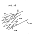
- connecting members 105 may be connected along the strut members 308 of the distal anchor 104 as shown in Figure 3E .
- connections between the connecting members 105 and the anchor 104 may be made at every inflection point around the circumference of the structure; or alternatively, at a subset of the inflection points around the circumference of the structure. In other words, connected inflection points alternate with unconnected inflection points in some defined pattern.
- the distal anchor 104 secures the prosthetic valve 100 to the inside wall of a body vessel such as a vein, and provide anchor points for the connecting members 105. Once deployed in the desired location, the anchor 104 will expand to an outside diameter slightly larger that the inside diameter of the native vessel (not shown) and remain substantially rigid in place, anchoring the valve assembly to the vessel.
- the connecting members 105 preferably have an inferior radial stiffness, and will conform much more closely to the native diameter of the vessel, facilitating the operation and stability of the prosthetic valve 100.
- the stent anchor may also have spurs or barbs (not shown) protruding from its proximal or distal end to further assist anchoring the prosthetic valve.
- the membrane assembly 102 is formed from a flexible membrane-like biocompatible material shaped into a tubular structure with a closed or substantially closed end. Exemplary embodiments would include a cup or cone shaped tube.
- the flexible membrane may be elastic, semi-elastic or display little or no elasticity.
- One of skill in the art would appreciate that there are many different methods, some known in the art, which may be employed to manufacture the membrane assembly 102 from this material.
- the biocompatible material may be a biological material, such as a vein or small intestine submucosa (SIS) formed into a cup or pocket, but is preferably a synthetic material such as a polymer, for example an elastic or elastomeric polymer, including a fluoropolymer, fluoroelastomer, or a bioabsorbable material, such as a bioabsorbable polymer or bioabsorbable elastomer.
- Bioabsorbable materials may allow cells to grow and form a tissue membrane over the bioabsorbable membrane. The bioabsorbable membrane then absorbs into the body, leaving the tissue membrane in place to act as a new natural tissue valve.
- the membrane material may also be made from other synthetics, such as thin metallic materials or membranes.
- the membrane must be strong enough to resist tearing under normal use, yet thin enough to provide the necessary flexibility that allows the biocompatible membrane assembly 102 to open and close satisfactorily.
- the synthetic material may be, for example, reinforced with a fiber, such as an electro-statically spun (ESS) fiber, or formed from a porous foam, such as ePTFE, or a mesh.
- ESS electro-statically spun
- Particular ESS fibers suitable for the spinning process include fluoropolymers, such as a crystalline fluoropolymer with an 85/15% (weight/weight ratio) of vinylidene fluoride/hexafluoropropylene (VDF/HFP).
- fluoropolymers such as a crystalline fluoropolymer with an 85/15% (weight/weight ratio) of vinylidene fluoride/hexafluoropropylene (VDF/HFP).
- Solvay Solef ® 21508 and Kynarflex 2750-01 are two such examples.
- bioabsorbable polymers such as polyglycolic acid, polylactic acid, poly (paradioxanone), polycaprolactone, poly (trimethylenecarbonate) and their copolymers
- semicrystalline bioelastomers such as 60/40%(weight/weight ratio) of polylactic acid / polycaprolactone (PLA/PCL), 65/35 (weight/weight ratio) of polyglycolic acid/polycaprolactone (PGA/PCL), or nonabsorbable siliconized polyurethane, non-siliconized polyurethanes, siliconized polyureaurethane, including siliconized polyureaurethane end capped with silicone or fluorine end groups, or natural polymers in combination thereof.
- PLA/PCL polycaprolactone
- PGA/PCL polyglycolic acid/polycaprolactone
- siliconized polyureaurethane including siliconized polyureaurethane end capped with silicone or fluorine end groups, or natural polymers in combination thereof.
- the ESS formed membrane assembly 102 may also be coated with a polymer solution, such as fluoroelastomer.
- a polymer solution such as fluoroelastomer. The coating process may take place before the membrane assembly is attached to the cantilever valve struts 107 or connecting members 105, or after the membrane assembly 102 and structural frame 101 are assembled.
- the coating process may act to encapsulate and attach at least a portion of the spun ESS reinforcement fiber to the structural frame, in particular the cantilever valve strut 107 assembly or connecting members 105. It should be noted that in some embodiments of the invention, some movement between the membrane assembly 102 and the structural frame 101 is desired. Accordingly, not all of the ESS fiber spun structural frame 101 may be coated.
- the coating process may also remove some porosity of the membrane material. However, it may be desirable to maintain some porosity in particular embodiments to promote biological cell grown on and within the membrane tubular structure.
- the coating solution preferably comprises a polymer put into solution with a solvent. As the solvent evaporates, the polymer comes out of solution forming the coating layer. Accordingly, for the process to work properly, the solvent used in the coating solution should not dissolve or alter the ESS fibers being coated.
- a coating solution of 60/40% VDF/HFP in methanol has been found to be a suitable solution for coating an ESS fiber comprised of 85/15% VDF/HFP.
- the polymer comprising the coating is Daikin's Dai-E1 G701BP, which is a 60/40% VDF/HFP.
- Daikin's Dai-E1 T630 a thermoplastic elastomer based on vinylidene fluoride/hexafluoropropylene/tetrafluoroethylene. (VDF/HFP/TFE) can also be used.
- VDF/HFP/TFE thermoplastic elastomer based on vinylidene fluoride/hexafluoropropylene/tetrafluoroethylene.
- the membrane assembly is made from a micro-cellular foam or porous material, such as, for example an ePTFE membrane.
- the membrane assembly 102 is fabricated from a polymer material that can be processed such that it exhibits an expanded cellular structure, preferably expanded Polytetrafluoroethylene (ePTFE).
- ePTFE expanded Polytetrafluoroethylene
- the ePTFE tubing is made by expanding Polytetrafluoroethylene (PTFE) tubing, under controlled conditions, as is well known in the art. This process alters the physical properties that make it satisfactory for use in medical devices.
- PTFE Polytetrafluoroethylene
- the micro-cellular foam or porous material may be coated with a polymer.
- the polymer can be coated on the inside or outside surface of the ePTFE tube.
- the polymer may be coated on the inside and outside of the ePTFE tube.
- the polymer comprising the coating includes Daikin's Dai-E1 T630, a thermoplastic elastomer based on vinylidene fluoride/hexafluoropropylene/tetrafluoroethylene (VDF/HFP/TFE) and blends thereof.
- VDF/HFP/TFE vinylidene fluoride/hexafluoropropylene/tetrafluoroethylene
- other polymers such as siliconized polyurethanes and blends thereof, including Polymer Technology Group's Pursil, Carbosil, Purspan and Purspan F.
- the membrane assembly 102 formed from the micro-cellular foam or porous membrane may also be coated with a fluoroelastomer.
- the coating is Daikin G701BP, which is a 60/40% VDF/HFP.
- other materials having suitable characteristics might be used for the coating, for example, other polymers, such as siliconized polyurethane.
- the coating process may take place before the membrane assembly is attached to the structural frame 101, or after the membrane assembly 102 and structural frame 101 are assembled.
- the coating process may act to encapsulate and attach at least a portion of the micro-cellular foam or porous membrane tube to the structural frame 101.
- Some post processing of the membrane assembly 102 may also take place to achieve particular desired characteristics or configurations. This may includes creating the final closed or substantially closed cup or cone shape of the membrane assembly 102 if needed.
- post processing may change the characteristics of the membrane assembly 102 by thickening or thinning the membrane in particular locations. Thickening the membrane may add rigidity and reinforcement to a particular area. Thinning the membrane may make the membrane more pliable, which is a desirable characteristic.
- Still other post processing procedures may change the physical shape of the membrane assembly 102, for example, by forming loop collars (such as loop collars 605 in Figures 6A through6C) along the distal edge of membrane assembly 102.
- the thickness of the synthetic valve membrane assembly 102 is dependent on the size, type and location of the prosthetic valve. For venous valves applications a polymeric membrane assembly 102 having a thickness of between 12 ⁇ m and 100 ⁇ m and preferably between 25 ⁇ m and 50 ⁇ m has been found to be acceptable.
- the membrane assembly 102 is placed or formed over the structural frame 101, similar to a graft.
- the membrane assembly 102 is formed into a closed end or substantially closed end tube over at least a portion of the connecting members 105.
- the cantilever valve struts 107 are then placed over the outer surface of the membrane assembly 102.
- the connecting members 105 and the cantilever valve struts 107 act to support the membrane assembly in a substantially tubular configuration.
- the membrane assembly 102 may be formed into the tubular configuration separately, and then placed over the structural frame 101.
- the membrane assembly 102 may be formed into the tubular configuration directly over the structural frame 101, such as by an electrostatic spinning process that spins the ESS fiber directly over the structural frame. This process is disclosed in a co pending patent application, publication number US-A-2003/0209835 entitled METHOD OF FORMING A TUBULAR MEMBRANE ON A STRUCTURAL FRAME, filed on March 28, 2004.
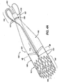
- FIGS 4A and 4B are perspective and section views, respectively, illustrating one embodiment of the expanded (deployed) prosthetic venous valve assembly 100 in the open position.
- the term open means that the prosthetic venous valve 100 is configured to allow antegrade blood flow 400 to pass through the valve.
- the membrane assembly 102 is in a substantially collapsed position.
- the embodiment illustrated in Figures 4A and 4B has three connecting members 105 and three cantilever valve struts 107.
- the membrane assembly 102 is placed over a portion of the structural frame 101, particularly over the connecting members 105, proximal collar 108 and at least a portion of the loop end 112 of the cantilever valve struts 107.
- a compression ring 109 may be used to fix the membrane assembly 102 to the proximal collar 108.
- the ring 109 should be sized to apply a radially compressive force on the membrane assembly 102, effectively fixing the membrane assembly 102 against the proximal collar 108.
- the flexible membrane assembly illustrated in Figure 4A is formed into a tubular cone having a first (distal) and second (proximal) ends 401, 402 respectively.
- the first end 401 of the membrane assembly 102 is located at the distal end of the cantilever valve struts 107, near the proximal end of the distal anchor 104, and is capable of opening to substantially the full diameter of the native vessel.
- the membrane assembly 102 is fixedly attached along the distal end of the cantilever valve struts 107 and connecting members 105.
- the membrane assembly 102 may be slidably attached to the connecting members 105. This configuration may assist the membrane assembly 102 when opening and closing.
- the membrane assembly extends in a proximal direction along the connecting members 105 and terminates at the second end 402.
- the second (proximal) end 402 of the membrane assembly 102 is fixedly or slideably attached along the loop end 112 of the cantilever valve struts 107.
- the proximal end 402 of the membrane assembly 102 has an open end with a substantially reduced cross-sectional area. As previously disclosed, the proximal end 402 may alternatively terminate with a closed cup or cone end.
- proximal end 402 may terminate at the proximal collar 108 with a closed or open end.
- valve assembly 100 having a single cone or cup, and may be considered a monocusp design. However, other configurations using more than a single cup or cone are also contemplated by the present invention.
- the membrane assembly 102 quickly fills with the retrograde flowing blood, expanding and opening the membrane assembly 102.
- the membrane assembly 102 will expand to a sufficient diameter to substantially seal against the inner vessel wall.
- the membrane assembly 102 may have a closed or substantially closed proximal end 402.
- the proximal opening must be of a sufficiently reduced cross-sectional area to substantially reduce or prevent the flow of fluid through the proximal end 402 of the membrane assembly 102.
- the proximal end 402 of the membrane assembly 102 is a substantially closed end tube (open but having a reduced cross-sectional area) disposed about the proximal loop end 112 of the cantilever valve struts 107.
- the proximal end 402 of the membrane assembly 102 is disposed about the cantilever valve strut 107 in close proximity to the interface between the cantilever valve strut 107 and proximal collar 108.
- the membrane assembly 102 and cantilever valve strut 107 are configured such that when the valve is in the open position (collapsed to allow blood flow to pass through the valve), the proximal loop ends 112 of the cantilever valve struts 107 are separated and allow the proximal end 402 of the membrane assembly to remain in an open tubular position.
- the proximal loop ends 112 of the cantilever valve struts 107 move closer together, urging the proximal end 402 of the membrane assembly 102 together. This movement substantially or completely closes the proximal end 402 of the membrane assembly 102, allowing the membrane assembly to substantially or completely occlude the vessel.
- FIGS 5A and 5B show perspective and section views, respectively, illustrating one embodiment of the expanded (deployed) prosthetic venous valve assembly 100 in the closed position.
- closed means that the prosthetic venous valve 100 is configured to substantially prohibit retrograde blood flow 410 to pass through the valve.
- the membrane assembly 102 is in an expanded position, substantially occluding the vessel.
- the membrane assembly 102 is normally configured in the open position (membrane assembly 102 substantially collapsed), and only moves to the closed position (membrane assembly 102 substantially expanded) upon retrograde blood flow.
- This configuration minimizes interference with blood flow (minimized occlusion) and reduces turbulence at and through the valve.
- the cantilever valve struts 107 in this embodiment have an inferior radial stiffness, and provide a natural bias against the movement of the membrane assembly 102 to the closed position. This bias assists the valve membrane assembly 102 when returning to the open position.
- the bias towards opening the prosthetic valve 100 may also be desirable for the bias towards opening the prosthetic valve 100 (collapsing the membrane assembly 102) be sufficiently high to commence collapsing the membrane assembly 102 before antegrade blood flow begins, i.e. during a point in time when the blood flow is stagnant (there is neither antegrade nor retrograde blood flow), or when minimal retrograde flow is experienced.
- valve assembly 100 normally configured in the closed position (membrane assembly 102 in the expanded position), biased closed, and only open upon antegrade flow.
- the membrane assembly 102 is made from a flexible membrane-like biocompatible material.
- the membrane assembly 102 can be woven, non-woven (such as electrostatic spinning), mesh, knitted, film or porous film (such as foam).
- the membrane assembly 102 may be fixedly attached to the structural frame 101 (particularly cantilever valve struts 107 and/or connecting members 105) by many different methods, including attachment by means of a binder, heat, or chemical bond, and/or attachment by mechanical means, such as welding or suturing.
- some of the membrane assembly 102 such as distal end 401, is slideably attached to the connecting member 105. Allowing the distal end 401 to slide along the connecting member 105 107 may allow or improve the opening and closing of the membrane assembly 102. The sliding movement may also assist the membrane assembly 102 cup when filling and emptying.
- a limiting means may be integrated into the prosthetic valve 100 to limit the sliding movement of the membrane assembly 102. Examples of limiting means are shown in Figures 6A to 6C .
- a stop 600 (illustrated as stop 600A, 600B, and 600C in Figures 6A to 6C respectively) is integrated into the connecting member 105.
- the membrane assembly 102 is wrapped around the connecting member 105 and bonded to itself to form a loop collar 605.
- the loop collar 605 must be sized to inhibit the distal end 401 of the membrane assembly 102 from sliding past the stop 600.
- the connecting member 105 has a thickened or "bulbous" section forming stop 600A.
- Figure 6B illustrates an undulating stop 600B configuration.
- Figure 6C shows the stop 600C configured as a double bulbous section. It should be noted that the various configurations illustrated in Figures 6A through 6C are exemplary. One of ordinary skill in the art would understand that other configurations of stops may be used.
- therapeutic or pharmaceutic agents may be added to any component of the device during fabrication, including, for example, the ESS fiber, polymer or coating solution, membrane tube, structural frame or inner and outer membrane, to treat any number of conditions.
- therapeutic or pharmaceutic agents may be applied to the device, such as in the form of a drug or drug eluting layer, or surface treatment after the device has been formed.
- the therapeutic and pharmaceutic agents may include any one or more of the following: antiproliferative/antimitotic agents including natural products such as vinca alkaloids (i.e.
- paclitaxel i.e. etoposide, teniposide
- antibiotics dactinomycin (actinomycin D) daunorubicin, doxorubicin and idarubicin
- anthracyclines mitoxantrone, bleomycins, plicamycin (mithramycin) and mitomycin
- enzymes L-asparaginase which systemically metabolizes L-asparagine and deprives cells which do not have the capacity to synthesize their own asparagine
- antiplatelet agents such as G(GP) 11b/111a inhibitors and vitronectin receptor antagonists
- antiproliferative/antimitotic alkylating agents such as nitrogen mustards (mechlorethamine, cyclophosphamide and analogs, melphalan, chlorambucil), ethylenimines and methylmel
- anticoagulants heparin, synthetic heparin salts and other inhibitors of thrombin
- fibrinolytic agents such as tissue plasminogen activator, streptokinase and urokinase), aspirin, dipyridamole, ticlopidine, clopidogrel, abciximab
- antimigratory antisecretory (breveldin)
- antiinflammatory such as adrenocortical steroids (cortisol, cortisone, fludrocortisone, prednisone, prednisolone, 6 ⁇ -methylprednisolone, triamcinolone, betamethasone, and dexamethasone), non-steroidal agents (salicylic acid derivatives i.e.
Landscapes
- Health & Medical Sciences (AREA)
- Cardiology (AREA)
- Engineering & Computer Science (AREA)
- Biomedical Technology (AREA)
- Heart & Thoracic Surgery (AREA)
- Transplantation (AREA)
- Oral & Maxillofacial Surgery (AREA)
- Vascular Medicine (AREA)
- Life Sciences & Earth Sciences (AREA)
- Animal Behavior & Ethology (AREA)
- General Health & Medical Sciences (AREA)
- Public Health (AREA)
- Veterinary Medicine (AREA)
- Prostheses (AREA)
- Materials For Medical Uses (AREA)
Abstract
Description
- The present invention relates to a medical device, and more particularly to a frame based unidirectional flow prosthetic valve, and the method for fabricating such valve.
- The human body has numerous biological valves that control fluid flow through body lumens and vessels. For example the circulatory system has various heart valves that allow the heart to act as a pump by controlling the flow of blood through the heart chambers, veins, and aorta. In addition, the venous system has numerous venous valves that help control the flow of blood back to the heart, particularly from the lower extremities.
- These valves can become incompetent or damaged by disease, for example, phlebitis, injury, or the result of an inherited malformation. Heart valves are subject to disorders, such as mitral stenosis, mitral regurgitation, aortic stenosis, aortic regurgitation, mitral valve prolapse and tricuspid stenosis. These disorder are potentially life threatening. Similarly, incompetent or damaged venous valves usually leak, allowing the blood to improperly flow back down through veins away from the heart (regurgitation reflux or retrograde blood flow). Blood can then stagnate in sections of certain veins, and in particular, the veins in the lower extremities. This stagnation of blood raises blood pressure and dilates the veins and venous valves. The dilation of one vein may in turn disrupt the proper function of other venous valves in a cascading manner, leading to chronic venous insufficiency.
- Numerous therapies have been advanced to treat symptoms and to correct incompetent valves. Less invasive procedures include compression, elevation and wound care. However, these treatments tend to be somewhat expensive and are not curative. Other procedures involve surgical intervention to repair, reconstruct or replace the incompetent or damaged valves, particularly heart valves.
- Surgical procedures for incompetent or damaged venous valves include valvuloplasty, transplantation, and transposition of veins. However, these surgical procedures provide somewhat limited results. The leaflets of some venous valves are generally thin, and once the valve becomes incompetent or destroyed, any repair provides only marginal relief.
- As an alternative to surgical intervention, drug therapy to correct valvular incompetence has been utilized. Currently, however, there are no effective drug therapies available.
- Other means and methods for treating and/or correcting damaged or incompetent valves include utilizing xenograft valve transplantation (monocusp bovine pericardium), prosthetic/bioprosthetic heart valves and vascular grafts, and artificial venous valves. These means have all had somewhat limited results.
- What is needed is an artificial endovascular (endoluminal) valve for the replacement of incompetent biological human valves, particularly heart and venous valves. These valves may also find use in artificial hearts and artificial heart assist pumps used in conjunction with heart transplants. United States patent
6. 440, 164 discloses a prosthetic valve for implantation with a fluid conducting lumen within a body. - The present invention, relates to a medical device, and in particular, to a stent-based valve. It provides a prosthetic valve as claimed hereinafter.
-
-
Figure 1A shows a perspective view of a prosthetic venous valve in the deployed state according to one embodiment of the present invention. -
Figure 2A shows a perspective view of the prosthetic venous valve structural frame in the deployed state according to one embodiment of the present invention. -
Figure 2B shows a perspective view of the prosthetic venous valve structural frame having helical connecting members according to one embodiment of the present invention. -
Figure 2C shows a perspective view of the prosthetic venous valve structural frame having a sinusoidal cantilever valve strut assembly according to one embodiment of the present invention. -
Figure 2D shows a perspective view of the prosthetic venous valve structural frame having a helical valve strut assembly according to one embodiment of the present invention. -
Figure 2E shows a perspective view of the prosthetic venous valve structural frame having a proximal centering mechanism in the deployed state according to one embodiment of the present invention. -
Figure 2F shows a perspective view of the prosthetic venous valve structural frame having distal and proximal anchor mechanisms according to one embodiment of the present invention. -
Figure 3A shows a perspective view of the distal stent anchor having a plurality of hoop structures according to one embodiment of the present invention. -
Figure 3B shows a close-up perspective view of a loop member from the anchor having inner and outer radii according to one embodiment of the present invention. -
Figure 3C illustrates a single hoop anchor having three connecting members connected to the proximal end of the distal anchor at the outer radii of the inflection point of the loop members. -
Figure 3D illustrates a single hoop anchor having three connecting members connected to the proximal end of the distal anchor at the inner radii of the inflection point of the loop members. -
Figure 3E illustrates a single hoop anchor having three connecting members connected to the proximal end of the distal anchor along the strut members connecting the loop members. -
Figure 4A is a perspective view illustrating one embodiment of the deployed prosthetic venous valve assembly in the open position. -
Figure 4B is a section view illustrating one embodiment of the deployed prosthetic venous valve assembly in the open position. -
Figure 5A is a perspective view illustrating one embodiment of the deployed prosthetic venous valve assembly in the closed position. -
Figure 5B is a section view illustrating one embodiment of the deployed prosthetic venous valve assembly in the closed position. -
Figure 6A is a perspective view illustrating a membrane limiting means according to one embodiment of the present invention. -
Figure 6B is a perspective view illustrating a membrane limiting means according to one embodiment of the present invention. -
Figure 6C is a perspective view illustrating a membrane limiting means according to one embodiment of the present invention. - The stent-based valves of the present invention provide a method for overcoming the difficulties associated with the treatment of valve insufficiency. Although stent based venous valves are disclosed to illustrate one embodiment of the present invention, one of ordinary skill in the art would understand that the disclosed invention can be equally applied to other locations and lumens in the body, such as, for example, coronary, vascular, non-vascular and peripheral vessels, ducts, and the like, including but not limited to cardiac valves, venous valves, valves in the esophagus and at the stomach, valves in the ureter and/or the vesica, valves in the biliary passages, valves in the lymphatic system and valves in the intestines.
- In accordance with one aspect of the present invention, the prosthetic valve is designed to be percutaneously delivered through a body lumen to a target site by a delivery catheter. The target site may be, for example, a location in the venous system adjacent to an insufficient venous valve. Once deployed the prosthetic venous valve functions to assist or replace the incompetent or damaged natural valve by allowing normal blood flow (antegrade blood flow) and preventing or reducing backflow (retrograde blood flow).
- A perspective view of a prosthetic venous valve in the deployed state according to one embodiment of the present invention is shown in
Figure 1 . The prostheticvenous valve 100 comprises astructural frame 101 and abiocompatible membrane assembly 102. Themembrane assembly 102 is a thin-walled biocompatible material formed into a tube with a closed end. Exemplary configurations of a closed end tube would include a tubular cup or cone shape, however one of skill in the art would understand that other configurations could also be used. - Alternatively, the cup or cone end of
membrane assembly 102 may also be partially open, having a cross-sectional area that is substantially smaller than the open end of the membrane assembly. This reduced cross-sectional area must be sized to effectively minimize or reduce fluid flow past theprosthetic valve 100, substantially occluding the vessel, when thevalve 100 is in the closed (expanded) position. The partially open-end configuration will allow fluid to pass through the tube (membrane assembly 102) during antegrade blood flow, preventing or reducing fluid stagnation within the tube. In applications where theprosthetic valve 100 is placed in the bloodstream, this reduced stagnation or pooling may decrease the risk of clotting. - For clarity, a perspective view of the prosthetic
venous valve 100structural frame 101 according to one embodiment of the present invention is shown inFigure 2A . Thestructural frame 101 consists of ananchor structure 104 connected by at least one connectingmember 105 to aproximal collar 108. In a preferred embodiment, at least three connectingmembers 105 are utilized. By way of example, the embodiment illustrated inFigure 2A shows four connectingmembers 105. - One or more cantilever valve struts 107 extend from the
proximal collar 108 in a proximal direction (upstream) before looping back in a distal (downstream) direction substantially parallel to thestructural frame 101longitudinal axis 106. This configuration allows thecantilever valve strut 107 to be longer, increasing the flexibility of thestruts 107 and helping to reduce the strains imposed in thestructural frame 101 and/ormembrane assembly 102. The cantilever valve struts 107 are attached to the biocompatible membrane assembly 102 (not shown inFigure 2A ) and further support the assembly in the open and closed positions. Theproximal collar 108 serves as a connection point between the one or movevalve strut members 107 and the one or more connectingmembers 105. - Each of the cantilever valve struts 107 illustrated in
Figure 2A have aloop end 112 incorporated into the proximal end and a single branchdistal end 113. Theloop end 112 of thevalve strut 107 is attached directly to the proximal end of theproximal collar 108, and has a semi-circular configuration, substantially symmetric about its center. This configuration allows theloop end 112 to effectively reverse the direction of thecantilever valve strut 107 from a proximal direction, where it attaches to the proximal end ofproximal collar 108, to a distal direction. - In a preferred embodiment, at least three cantilever valve struts 107 are utilized. In the embodiment illustrated in
Figures 2A four cantilever valve struts 107 are shown. - The number of cantilever valve struts 107 and connecting
members 105 illustrated are not meant to limit the scope of the invention. One of skill in the art would understand that other quantities and combinations of valve struts 107 and connectingmembers 105 could be used and still accomplish the general intent of the invention. - In addition, the
structural frame 101, particularly the connectingmembers 105 and/or cantilever valve struts 107 may include radiopaque markers or marker bands attached or integrated thereto. The radiopaque markers are opaque to radiation, especially to X rays and MRI, allowing the position of thestructural frame 101 or its components to be viewed "in vivo".Figure 1 illustratesmarker bands 103 along thecantilever valve strut 107 members. - It should be noted that the terms proximal and distal are typically used to connote a direction or position relative to a human body. For example, the proximal end of a bone may be used to reference the end of the bone that is closer to the center of the body. Conversely, the term distal can be used to refer to the end of the bone farthest from the body. In the vasculature, proximal and distal are sometimes used to refer to the flow of blood to the heart, or away from the heart, respectively. Since the prosthetic valves described in this invention can be used in many different body lumens, including both the arterial and venous system, the use of the terms proximal and distal in this application are used to describe relative position in relation to the direction of fluid flow. As used herein, the terms upstream and downstream are relative to the normal direction of fluid flow (antegrade flow). By way of example, for venous valves, downstream connotes a direction of blood flow toward the heart. Accordingly, the use of the term proximal in the present application describes an upstream member, section or relative position, regardless of its orientation relative to the body. The use of the term distal is used to describe a downstream member, section or relative position regardless of its orientation relative to the body. Similarly, the use of the terms proximal and distal to connote a direction describe upstream (retrograde) or downstream (antegrade) respectively.
- In the embodiment illustrated in
Figures 2A , the connectingmembers 105 are substantially linear members, connecting the stent baseddistal anchor 104 and theproximal collar 108. Alternatively, the connectingmembers 105 may be twisted in a helical fashion as they extend between theproximal collar 108 and thedistal anchor 104. This alternate embodiment is illustrated inFigure 2B . Specifically, the connection points between the connectingmembers 105 and thedistal anchor 104, and the connectingmembers 105 and theproximal collar 108, are rotationally phased 180 degrees from each other to provide the helical design. - Similarly, the
distal end 113 of the cantilever valve struts 107 are illustrated as substantially straight members, but may take on other configurations. By way of example,Figure 2C shows astructural frame 101 having sinusoidal cantilever valve struts 107 along thedistal end 113, whileFigure 2D shows astructural frame 101 having helical cantilever valve struts 107 along thedistal end 113. These various configurations may be used to change the properties of the structural frame, for example, by providing more flexibility in a particular plane or direction. Still other configurations are possible as would be understood by one of skill in the art. - The
structural frame 101 could also include a secondary mechanism to center the proximal end of the frame in the body vessel or lumen. This mechanism may also provide additional anchoring to the vessel wall to further stabilize theprosthetic valve 100. -
Figure 2E shows a centeringmechanism 205 incorporated into the proximal end of thestructural frame 101 according to one embodiment of the present invention. The centeringmechanism 205 is comprised of one ormore legs 210 that extend in a substantially radial direction from thelongitudinal centerline 106 to the vessel wall (not shown). In the illustrated embodiment, 4legs 210 are shown for the purpose of example. Thelegs 210 terminate with a blunt end, such as the curved bend illustrated, to reduce the possibility of the leg end perforating the vessel wall. The opposite end of theleg 210 is attached to the structural frame at or near theproximal collar 108. In the embodiment illustrated inFigure 2E , the centeringlegs 210 are cut from the same tube as the remainder of thestructural frame 101 such that thestructural frame 101, includinglegs 210, is a one piece unit. Alternatively, the centeringlegs 210. may be separate wire units and crimped or suitably attached to thestructural frame 101 at theproximal collar 108. Theleg 210 may includebarbs 215 on or along the end portion to further anchor thestructural frame 101 to the vessel wall. - The
structural frame 101 may also include asecond anchor mechanism 203, similar toanchor 104, as shown inFigure 2F . Aside from providing additional support and anchoring for the proximal end of thestructural frame 101, theproximal anchor 203 may also act as a centering mechanism to center the proximal end of thestructural frame 101 in the vessel or lumen (not shown). Theproximal anchor 203 may be attached directly to thestructural frame 101 at theproximal collar 108, or may be attached to the proximal collar by connectingmembers 206 as shown inFigure 2F . As disclosed above, theproximal anchor 203 and connectingmembers 206 may be cut from the same tube as the remainder of thestructural frame 101 such that thestructural frame 101, including theanchor 203 and connectingmembers 206, is a one piece unit. Alternatively, theanchor 203 and connectingmembers 206 may be separate units crimped or suitably attached to thestructural frame 101 at theproximal collar 108. - The materials for the
structural frame 101 should exhibit excellent corrosion resistance and biocompatibility. In addition, the material comprising thestructural frame 101 should be sufficiently radiopaque and create minimal artifacts during MRI. - The present invention contemplates deployment of the prosthetic
venous valve 100 by both assisted (mechanical) expansion, i.e. balloon expansion, and self-expansion means. In embodiments where the prostheticvenous valve 100 is deployed by mechanical (balloon) expansion, thestructural frames 101 is made from materials that can be plastically deformed through the expansion of a mechanical assist device, such as by the inflation of a catheter based balloon. When the balloon is deflated, theframe 101 remains substantially in the expanded shape. Accordingly, the ideal material has a low yield stress (to make theframe 101 deformable at manageable balloon pressures), high elastic modulus (for minimal recoil), and is work hardened through expansion for high strength. The most widely used material for balloonexpandable structures 101 is stainless steel, particularly 316L stainless steel. This material is particularly corrosion resistant with a low carbon content and additions of molybdenum and niobium. Fully annealed, stainless steel is easily deformable. - Alternative materials for mechanically expandable
structural frames 101 that maintain similar characteristics to stainless steel include tantalum, platinum alloys, niobium alloys, and cobalt alloys. In addition other materials, such as polymers and bioabsorbable polymers may be used for thestructural frames 101. - Where the prosthetic
venous valve 100 is self-expanding, the materials comprising thestructural frame 101 should exhibit large elastic strains. A suitable material possessing this characteristic is Nitinol, a Nickel-Titanium alloy that can recover elastic deformations of up to 10 percent. This unusually large elastic range is commonly known as superelasticity. - The disclosure of various materials comprising the structural frame should not be construed as limiting the scope of the invention. One of ordinary skill in the art would understand that other material possessing similar characteristics may also be used in the construction of the prosthetic
venous valve 100. For example, bioabsorbable polymers, such as polydioxanone may also be used. Bioabsorbable materials absorb into the body after a period of time. The period of time for thestructural frame 101 to absorb may vary, but is typically sufficient to allow adequate tissue growth at the implant location to adhere to and anchor thebiocompatible membrane 102. - The
structural frame 101 may be fabricated using several different methods. Typically, thestructural frame 101 is constructed from sheet, wire (round or flat) or tubing, but the method of fabrication generally depends on the raw material form used. - The
structural frame 101 can be formed from wire using convention wire forming techniques, such as coiling, braiding, or knitting. By welding the wire at specific locations a closed-cell structure may be created. This allows for continuous production, i.e. the components of thestructural frame 101, such as the anchors, to be cut to length from a long wire mesh tube. The connecting members (i.e. 206, 105) may then be attached to the proximal and distal anchors (i.e. 203, 104 respectively), by welding or other suitable connecting means. When this fabrication method is used, theproximal collar 108 may also be crimped over the wire frame ends (i.e. connecting members, cantilever struts, and/or centering legs) to connect the individual members together. Alternatively, the wire ends may be attached to theproximal collar 108 by welding or other suitable connecting means. - Alternatively, some or all of the complete
structural frame 101 may be cut from a solid wall tube or sheet of material. Laser cutting, water-jet cutting and photochemical etching are all methods that can be employed to form thestructural frame 101 from sheet and tube stock as are known in the art. - Referring to
Figure 2A for example, the structural frame 101 (including thedistal anchor 104, connectingmembers 105, cantilever valve struts 107 and proximal collar 108) may all be cut from a solid tube eliminating the need for welding or mechanically attaching individual components together. In this embodiment, theproximal collar 108 shown is the actual pre-cut solid wall tube (and remains in the pre-cut, pre-expansion size), while the remainder of the components comprising thestructural frame 101 are shown in the expanded (deployed) position. As one of skill in the art would understand, theproximal collar 108 serves as a common termination point for the cantilever valve struts 107 and connectingmembers 105. - In other embodiments, the
proximal anchor 203 or centeringlegs 210 may similarly be cut from the same solid wall tube as the remainder of thestructural frame 101. - Alternatively, the connecting
members 105 and cantilever valve struts 107 may be separate loose components, and tied to each other by theproximal collar 108. In this configuration, theproximal collar 108 acts as a connection point to connect or crimp down and hold the loose members in place. In other embodiments disclosed above, the centeringlegs 210, connectingmembers 206 and/orproximal anchor 203 may also be fabricated separate from the otherstructural frame 101 components, and similarly attached or crimped in place at theproximal collar 108. - As discussed above, the disclosure of various methods for constructing the
structural frame 101 should not be construed as limiting the scope of the invention. One of ordinary skill in the art would understand that other construction methods may be employed to form thestructural frame 101 of the prostheticvenous valve 100. - In one embodiment of the invention, the anchor 104 (and in other particular embodiments, proximal anchor 203) are stent-based structures. This configuration facilitates the percutaneous delivery of the prosthetic
venous valve 100 through the vascular system in a compressed state. Once properly located, the stent-basedvenous valve 100 may be deployed to the expanded state. - A perspective views of a typical stent-based anchor in the expanded (deployed) state is shown in
Figures 3A . Althoughstent anchor 104 incorporating a plurality of hoop structures (306A through 306D) is shown in the illustrated embodiment, each stent anchor may utilize a single hoop structure. - The distal stent anchor 104 (and in some embodiments proximal stent anchor 203) is comprised of a tubular configuration of structural elements having proximal and distal open ends and defining the
longitudinal axis 106 extending therebetween. Thestent anchor 104 has a first diameter (not shown) for insertion into a patient and navigation through the vessels, and a second diameter D2 for deployment into the target area of a vessel, with the second diameter being greater than the first diameter. Thestent anchor 104, and thus the stent basedvenous valve 100, may be either a mechanical (balloon) or self-expanding stent based structure. - The
stent anchor 104 comprises at least one hoop structure 306 (306A through 306D are shown) extending between the proximal and distal ends. Thehoop structure 306 includes a plurality of longitudinally arrangedstrut members 308 and a plurality ofloop members 310 connectingadjacent struts 308.Adjacent struts 308 are connected at opposite ends in a substantially S or Z shaped pattern so as to form a plurality of cells. The plurality ofloops 310 have a substantially semi-circular configuration, having aninter radii 312 andouter radii 314, and are substantially symmetric about their centers. The inner andouter radii Figure 3B . - In the illustrated embodiment, the
distal stent anchor 104 comprises a plurality ofbridge members 314 that connectadjacent hoops 306A through 306D. Eachbridge member 314 comprises twoends end bridge 314 is attached to one loop on one hoop. Usinghoop sections 306C and 306D for example, eachbridge member 314 is connected atend 316A toloop 310 onhoop section 306C at apoint 320. Similarly, theopposite end 316B of eachbridge member 314 is connected toloop 310 on hoop sections 306D at apoint 321. - As described earlier, although a Z or S shaped pattern stent anchor is shown for the purpose of example, the illustration is not to be construed as limiting the scope of the invention. One of ordinary skill in the art would understand that other stent geometries may be used.
- The connecting
member 105 may be connected to thedistal anchor 104 at various points along the structure. As illustrated inFigure 3A , the connectingmembers 105 are connected to the proximal end of thedistal anchor 104 at the inflection point of theloop members 310, particularly at theouter radii 314 of the inflection point ofloop members 310. Similarly,Figure 3C illustrates asingle hoop anchor 104 having three connectingmembers 105 connected to the proximal end of thedistal anchor 104 at theouter radii 314 of the inflection point ofloop members 310. - Preferably the connecting
members 105 are connected to the inflection point ofloop members 310 at evenly spaced intervals along the circumference of thetubular anchor 104. This configuration facilitates the radial expansion of the prosthetic valve from the collapsed (delivered) state to the expanded (deployed) state, and provides a substantially symmetrical valve configuration. - Alternatively, the connecting
members 105 may be connected to the proximal end of thedistal anchor 104 at theinner radii 312 of the inflection point ofloop member 310. This configuration is illustrated inFigure 3D. Figure 3D also illustrates a partial perspective view of thestructural frame 101 having asingle hoop structure 306 and three connecting members. - In still a further embodiment, the connecting
members 105 may be connected along thestrut members 308 of thedistal anchor 104 as shown inFigure 3E . - In any of the above described configurations, the connections between the connecting
members 105 and theanchor 104 may be made at every inflection point around the circumference of the structure; or alternatively, at a subset of the inflection points around the circumference of the structure. In other words, connected inflection points alternate with unconnected inflection points in some defined pattern. - The
distal anchor 104 secures theprosthetic valve 100 to the inside wall of a body vessel such as a vein, and provide anchor points for the connectingmembers 105. Once deployed in the desired location, theanchor 104 will expand to an outside diameter slightly larger that the inside diameter of the native vessel (not shown) and remain substantially rigid in place, anchoring the valve assembly to the vessel. The connectingmembers 105 preferably have an inferior radial stiffness, and will conform much more closely to the native diameter of the vessel, facilitating the operation and stability of theprosthetic valve 100. - The stent anchor may also have spurs or barbs (not shown) protruding from its proximal or distal end to further assist anchoring the prosthetic valve.
- The
membrane assembly 102 is formed from a flexible membrane-like biocompatible material shaped into a tubular structure with a closed or substantially closed end. Exemplary embodiments would include a cup or cone shaped tube. The flexible membrane may be elastic, semi-elastic or display little or no elasticity. One of skill in the art would appreciate that there are many different methods, some known in the art, which may be employed to manufacture themembrane assembly 102 from this material. - The biocompatible material may be a biological material, such as a vein or small intestine submucosa (SIS) formed into a cup or pocket, but is preferably a synthetic material such as a polymer, for example an elastic or elastomeric polymer, including a fluoropolymer, fluoroelastomer, or a bioabsorbable material, such as a bioabsorbable polymer or bioabsorbable elastomer. Bioabsorbable materials may allow cells to grow and form a tissue membrane over the bioabsorbable membrane. The bioabsorbable membrane then absorbs into the body, leaving the tissue membrane in place to act as a new natural tissue valve.
- The membrane material may also be made from other synthetics, such as thin metallic materials or membranes.
- The membrane must be strong enough to resist tearing under normal use, yet thin enough to provide the necessary flexibility that allows the
biocompatible membrane assembly 102 to open and close satisfactorily. To achieve the necessary flexibility and strength of themembrane assembly 102, the synthetic material may be, for example, reinforced with a fiber, such as an electro-statically spun (ESS) fiber, or formed from a porous foam, such as ePTFE, or a mesh. - Particular ESS fibers suitable for the spinning process include fluoropolymers, such as a crystalline fluoropolymer with an 85/15% (weight/weight ratio) of vinylidene fluoride/hexafluoropropylene (VDF/HFP). Solvay Solef® 21508 and Kynarflex 2750-01 are two such examples. However, one of skill in the art would understand that any material possessing the desired characteristics may be used, including, for example: bioabsorbable polymers, such as polyglycolic acid, polylactic acid, poly (paradioxanone), polycaprolactone, poly (trimethylenecarbonate) and their copolymers; and semicrystalline bioelastomers, such as 60/40%(weight/weight ratio) of polylactic acid / polycaprolactone (PLA/PCL), 65/35 (weight/weight ratio) of polyglycolic acid/polycaprolactone (PGA/PCL), or nonabsorbable siliconized polyurethane, non-siliconized polyurethanes, siliconized polyureaurethane, including siliconized polyureaurethane end capped with silicone or fluorine end groups, or natural polymers in combination thereof. It should be noted that poly(trimethylenecarbonate) can not be spun as a homopolymer.
- The ESS formed
membrane assembly 102 may also be coated with a polymer solution, such as fluoroelastomer. The coating process may take place before the membrane assembly is attached to the cantilever valve struts 107 or connectingmembers 105, or after themembrane assembly 102 andstructural frame 101 are assembled. - The coating process may act to encapsulate and attach at least a portion of the spun ESS reinforcement fiber to the structural frame, in particular the
cantilever valve strut 107 assembly or connectingmembers 105. It should be noted that in some embodiments of the invention, some movement between themembrane assembly 102 and thestructural frame 101 is desired. Accordingly, not all of the ESS fiber spunstructural frame 101 may be coated. - The coating process may also remove some porosity of the membrane material. However, it may be desirable to maintain some porosity in particular embodiments to promote biological cell grown on and within the membrane tubular structure.
- The coating solution preferably comprises a polymer put into solution with a solvent. As the solvent evaporates, the polymer comes out of solution forming the coating layer.
Accordingly, for the process to work properly, the solvent used in the coating solution should not dissolve or alter the ESS fibers being coated. By way of example, a coating solution of 60/40% VDF/HFP in methanol (methanol being the solvent) has been found to be a suitable solution for coating an ESS fiber comprised of 85/15% VDF/HFP. - In one embodiment of the invention, the polymer comprising the coating is Daikin's Dai-E1 G701BP, which is a 60/40% VDF/HFP. In addition, Daikin's Dai-E1 T630, a thermoplastic elastomer based on vinylidene fluoride/hexafluoropropylene/tetrafluoroethylene. (VDF/HFP/TFE) can also be used. Again, one of ordinary skill in the art would understand that other materials having suitable characteristics may be used for the coating, for example, other polymers, such as siliconized polyurethane, including Polymer Technology Group's Pursil, Carbosil, Purspan and Purspan F.
- In another embodiment the membrane assembly is made from a micro-cellular foam or porous material, such as, for example an ePTFE membrane.
- In this embodiment, the
membrane assembly 102 is fabricated from a polymer material that can be processed such that it exhibits an expanded cellular structure, preferably expanded Polytetrafluoroethylene (ePTFE). The ePTFE tubing is made by expanding Polytetrafluoroethylene (PTFE) tubing, under controlled conditions, as is well known in the art. This process alters the physical properties that make it satisfactory for use in medical devices. However, one of ordinary skill in the art would understand that other materials that possess the necessary characteristics could also be used. - The micro-cellular foam or porous material (preferably expanded Polytetrafluoroethylene (ePTFE)) may be coated with a polymer. The polymer can be coated on the inside or outside surface of the ePTFE tube. Alternatively, the polymer may be coated on the inside and outside of the ePTFE tube.
- In a preferred embodiment of the invention, the polymer comprising the coating includes Daikin's Dai-E1 T630, a thermoplastic elastomer based on vinylidene fluoride/hexafluoropropylene/tetrafluoroethylene
(VDF/HFP/TFE) and blends thereof. Again, one of ordinary skill in the art would understand that other materials having suitable characteristics may be used for the coating, for example, other polymers, such as siliconized polyurethanes and blends thereof, including Polymer Technology Group's Pursil, Carbosil, Purspan and Purspan F. - The
membrane assembly 102 formed from the micro-cellular foam or porous membrane may also be coated with a fluoroelastomer. In one embodiment of the invention, the coating is Daikin G701BP, which is a 60/40% VDF/HFP. Again, one of ordinary skill in the art would understand that other materials having suitable characteristics might be used for the coating, for example, other polymers, such as siliconized polyurethane. - As previously described, the coating process may take place before the membrane assembly is attached to the
structural frame 101, or after themembrane assembly 102 andstructural frame 101 are assembled. The coating process may act to encapsulate and attach at least a portion of the micro-cellular foam or porous membrane tube to thestructural frame 101. - Some post processing of the
membrane assembly 102 may also take place to achieve particular desired characteristics or configurations. This may includes creating the final closed or substantially closed cup or cone shape of themembrane assembly 102 if needed. In addition, post processing may change the characteristics of themembrane assembly 102 by thickening or thinning the membrane in particular locations. Thickening the membrane may add rigidity and reinforcement to a particular area. Thinning the membrane may make the membrane more pliable, which is a desirable characteristic. Still other post processing procedures may change the physical shape of themembrane assembly 102, for example, by forming loop collars (such asloop collars 605 inFigures 6A through6C) along the distal edge ofmembrane assembly 102. - The thickness of the synthetic
valve membrane assembly 102 is dependent on the size, type and location of the prosthetic valve. For venous valves applications apolymeric membrane assembly 102 having a thickness of between 12µm and 100µm and preferably between 25µm and 50µm has been found to be acceptable. - The
membrane assembly 102 is placed or formed over thestructural frame 101, similar to a graft. In particular, themembrane assembly 102 is formed into a closed end or substantially closed end tube over at least a portion of the connectingmembers 105. The cantilever valve struts 107 are then placed over the outer surface of themembrane assembly 102. The connectingmembers 105 and the cantilever valve struts 107 act to support the membrane assembly in a substantially tubular configuration. - The
membrane assembly 102 may be formed into the tubular configuration separately, and then placed over thestructural frame 101. Alternatively, themembrane assembly 102 may be formed into the tubular configuration directly over thestructural frame 101, such as by an electrostatic spinning process that spins the ESS fiber directly over the structural frame. This process is disclosed in a co pending patent application, publication numberUS-A-2003/0209835 entitled METHOD OF FORMING A TUBULAR MEMBRANE ON A STRUCTURAL FRAME, filed on March 28, 2004. -
Figures 4A and4B are perspective and section views, respectively, illustrating one embodiment of the expanded (deployed) prostheticvenous valve assembly 100 in the open position. In this embodiment, the term open means that the prostheticvenous valve 100 is configured to allow antegrade blood flow 400 to pass through the valve. To accomplish this, themembrane assembly 102 is in a substantially collapsed position. - The embodiment illustrated in
Figures 4A and4B has three connectingmembers 105 and three cantilever valve struts 107. Themembrane assembly 102 is placed over a portion of thestructural frame 101, particularly over the connectingmembers 105,proximal collar 108 and at least a portion of theloop end 112 of the cantilever valve struts 107. Acompression ring 109 may be used to fix themembrane assembly 102 to theproximal collar 108. Thering 109 should be sized to apply a radially compressive force on themembrane assembly 102, effectively fixing themembrane assembly 102 against theproximal collar 108. - The flexible membrane assembly illustrated in
Figure 4A is formed into a tubular cone having a first (distal) and second (proximal) ends 401, 402 respectively. Thefirst end 401 of themembrane assembly 102 is located at the distal end of the cantilever valve struts 107, near the proximal end of thedistal anchor 104, and is capable of opening to substantially the full diameter of the native vessel. In one embodiment of the invention, themembrane assembly 102 is fixedly attached along the distal end of the cantilever valve struts 107 and connectingmembers 105. Alternatively themembrane assembly 102 may be slidably attached to the connectingmembers 105. This configuration may assist themembrane assembly 102 when opening and closing. - The membrane assembly extends in a proximal direction along the connecting
members 105 and terminates at thesecond end 402. The second (proximal)end 402 of themembrane assembly 102 is fixedly or slideably attached along theloop end 112 of the cantilever valve struts 107. Theproximal end 402 of themembrane assembly 102 has an open end with a substantially reduced cross-sectional area. As previously disclosed, theproximal end 402 may alternatively terminate with a closed cup or cone end. - In an alternative embodiment, the
proximal end 402 may terminate at theproximal collar 108 with a closed or open end. - The illustrated embodiment shows a
valve assembly 100 having a single cone or cup, and may be considered a monocusp design. However, other configurations using more than a single cup or cone are also contemplated by the present invention. - During retrograde flow, blood passes the leading edge along the
first end 401 of themembrane assembly 102 and enters the interior (i.e. "cup") portion ofmembrane assembly 102. Themembrane assembly 102 quickly fills with the retrograde flowing blood, expanding and opening themembrane assembly 102. As themembrane assembly 102 opens, thefirst end 401 is forced out toward vessel wall, substantially occluding the vessel and thus reducing retrograde flow through the valve. In a preferred embodiment, themembrane assembly 102 will expand to a sufficient diameter to substantially seal against the inner vessel wall. - As previously described, the
membrane assembly 102 may have a closed or substantially closedproximal end 402. In embodiments where themembrane assembly 102proximal end 402 is substantially closed, the proximal opening must be of a sufficiently reduced cross-sectional area to substantially reduce or prevent the flow of fluid through theproximal end 402 of themembrane assembly 102. - In the embodiment illustrated in
Figure 4A , theproximal end 402 of themembrane assembly 102 is a substantially closed end tube (open but having a reduced cross-sectional area) disposed about theproximal loop end 112 of the cantilever valve struts 107. In particular, theproximal end 402 of themembrane assembly 102 is disposed about thecantilever valve strut 107 in close proximity to the interface between thecantilever valve strut 107 andproximal collar 108. Themembrane assembly 102 andcantilever valve strut 107 are configured such that when the valve is in the open position (collapsed to allow blood flow to pass through the valve), the proximal loop ends 112 of the cantilever valve struts 107 are separated and allow theproximal end 402 of the membrane assembly to remain in an open tubular position. When the valve closes during retrograde blood flow, the proximal loop ends 112 of the cantilever valve struts 107 move closer together, urging theproximal end 402 of themembrane assembly 102 together. This movement substantially or completely closes theproximal end 402 of themembrane assembly 102, allowing the membrane assembly to substantially or completely occlude the vessel. -
Figures 5A and5B show perspective and section views, respectively, illustrating one embodiment of the expanded (deployed) prostheticvenous valve assembly 100 in the closed position. As the term is used herein, closed means that the prostheticvenous valve 100 is configured to substantially prohibit retrograde blood flow 410 to pass through the valve. To accomplish this, themembrane assembly 102 is in an expanded position, substantially occluding the vessel. - In a preferred embodiment of the invention, the
membrane assembly 102 is normally configured in the open position (membrane assembly 102 substantially collapsed), and only moves to the closed position (membrane assembly 102 substantially expanded) upon retrograde blood flow. This configuration minimizes interference with blood flow (minimized occlusion) and reduces turbulence at and through the valve. The cantilever valve struts 107 in this embodiment have an inferior radial stiffness, and provide a natural bias against the movement of themembrane assembly 102 to the closed position. This bias assists thevalve membrane assembly 102 when returning to the open position. - Depending on the application, it may also be desirable for the bias towards opening the prosthetic valve 100 (collapsing the membrane assembly 102) be sufficiently high to commence collapsing the
membrane assembly 102 before antegrade blood flow begins, i.e. during a point in time when the blood flow is stagnant (there is neither antegrade nor retrograde blood flow), or when minimal retrograde flow is experienced. - In other applications, it may be desirable to have the
valve assembly 100 normally configured in the closed position (membrane assembly 102 in the expanded position), biased closed, and only open upon antegrade flow. - As earlier described, the
membrane assembly 102 is made from a flexible membrane-like biocompatible material. Themembrane assembly 102 can be woven, non-woven (such as electrostatic spinning), mesh, knitted, film or porous film (such as foam). - The
membrane assembly 102 may be fixedly attached to the structural frame 101 (particularly cantilever valve struts 107 and/or connecting members 105) by many different methods, including attachment by means of a binder, heat, or chemical bond, and/or attachment by mechanical means, such as welding or suturing. In one embodiment, some of themembrane assembly 102, such asdistal end 401, is slideably attached to the connectingmember 105. Allowing thedistal end 401 to slide along the connectingmember 105 107 may allow or improve the opening and closing of themembrane assembly 102. The sliding movement may also assist themembrane assembly 102 cup when filling and emptying. - In some applications, excessive sliding movement of the
membrane assembly 102 is undesirable. In these embodiments, a limiting means may be integrated into theprosthetic valve 100 to limit the sliding movement of themembrane assembly 102. Examples of limiting means are shown inFigures 6A to 6C . In each embodiment a stop 600 (illustrated asstop Figures 6A to 6C respectively) is integrated into the connectingmember 105. Themembrane assembly 102 is wrapped around the connectingmember 105 and bonded to itself to form aloop collar 605. Theloop collar 605 must be sized to inhibit thedistal end 401 of themembrane assembly 102 from sliding past the stop 600. InFigure 6A , the connectingmember 105 has a thickened or "bulbous"section forming stop 600A.Figure 6B illustrates an undulatingstop 600B configuration. Similarly,Figure 6C shows thestop 600C configured as a double bulbous section. It should be noted that the various configurations illustrated inFigures 6A through 6C are exemplary. One of ordinary skill in the art would understand that other configurations of stops may be used. - It is important to note that the local delivery of drug/drug combinations may be utilized to treat a wide variety of conditions utilizing any number of medical devices, or to enhance the function and/or life of the device. Medical devices that may benefit from this treatment include, for example, the frame based unidirectional flow prosthetic implant subject of the present invention.
- Accordingly, in addition to the embodiments described above, therapeutic or pharmaceutic agents may be added to any component of the device during fabrication, including, for example, the ESS fiber, polymer or coating solution, membrane tube, structural frame or inner and outer membrane, to treat any number of conditions. In addition, therapeutic or pharmaceutic agents may be applied to the device, such as in the form of a drug or drug eluting layer, or surface treatment after the device has been formed. In a preferred embodiment, the therapeutic and pharmaceutic agents may include any one or more of the following: antiproliferative/antimitotic agents including natural products such as vinca alkaloids (i.e. vinblastine, vincristine, and vinorelbine), paclitaxel, epidipodophyllotoxins (i.e. etoposide, teniposide), antibiotics (dactinomycin (actinomycin D) daunorubicin, doxorubicin and idarubicin), anthracyclines, mitoxantrone, bleomycins, plicamycin (mithramycin) and mitomycin, enzymes (L-asparaginase which systemically metabolizes L-asparagine and deprives cells which do not have the capacity to synthesize their own asparagine); antiplatelet agents such as G(GP) 11b/111a inhibitors and vitronectin receptor antagonists; antiproliferative/antimitotic alkylating agents such as nitrogen mustards (mechlorethamine, cyclophosphamide and analogs, melphalan, chlorambucil), ethylenimines and methylmelamines (hexamethylmelamine and thiotepa), alkyl sulfonates-busulfan, nirtosoureas (carmustine (BCNU) and analogs, streptozocin), trazenes dacarbazinine (DTIC) ; antiproliferative/antimitotic antimetabolites such as folic acid analogs (methotrexate), pyrimidine analogs (fluorouracil, floxuridine, and cytarabine), purine analogs and related inhibitors (mercaptopurine, thioguanine, pentostatin and 2-chlorodeoxyadenosine {cladribine}); platinum coordination complexes (cisplatin, carboplatin), procarbazine, hydroxyurea, mitotane, aminoglutethimide; hormones (i.e. estrogen); anticoagulants (heparin, synthetic heparin salts and other inhibitors of thrombin); fibrinolytic agents (such as tissue plasminogen activator, streptokinase and urokinase), aspirin, dipyridamole, ticlopidine, clopidogrel, abciximab; antimigratory; antisecretory (breveldin); antiinflammatory: such as adrenocortical steroids (cortisol, cortisone, fludrocortisone, prednisone, prednisolone, 6α-methylprednisolone, triamcinolone, betamethasone, and dexamethasone), non-steroidal agents (salicylic acid derivatives i.e. aspirin; para-aminophenol derivatives i.e. acetominophen; indole and indene acetic acids (indomethacin, sulindac, and etodalac), heteroaryl acetic acids (tolmetin, diclofenac, and ketorolac), arylpropionic acids (ibuprofen and derivatives), anthranilic acids (mefenamic acid, and meclofenamic acid), enolic acids (piroxicam, tenoxicam, phenylbutazone, and oxyphenthatrazone), nabumetone, gold compounds (auranofin, aurothioglucose, gold sodium thiomalate); immunosuppressives: (cyclosporine, tacrolimus (FK-506), sirolimus (rapamycin), azathioprine, mycophenolate mofetil); angiogenic agents: vascular endothelial growth factor (VEGF), fibroblast growth factor (FGF); angiotensin receptor blockers; nitric oxide donors; anti-sense oligionucleotides and combinations thereof; cell cycle inhibitors, mTOR inhibitors, and growth factor receptor signal transduction kinase inhibitors; retenoids; cyclin/CDK inhibitors; HMG co-enzyme reductase inhibitors (statins); and protease inhibitors.
- While a number of variations of the invention have been shown and described in detail, other modifications and methods of use contemplated within the scope of this invention will be readily apparent to those of skill in the art based upon this disclosure. It is contemplated that various combinations or subcombinations of the specific embodiments may be made and still fall within the scope of the invention. For example, the embodiments variously shown to be prosthetic "venous valves" may be modified to instead incorporate prosthetic "heart valves" and are also contemplated. Moreover, all assemblies described are believed useful when modified to threat other vessels or lumens in the body, in particular other regions of the body where fluid flow in a body vessel or lumen needs to be controlled or regulated. This may include, for example, the coronary, vascular, non-vascular and peripheral vessels and ducts. Accordingly, it should be understood that various applications, modifications and substitutions may be made of equivalents without departing from the scope of the following claims.
- The following claims are provided to illustrate examples of some beneficial aspects of the subject matter disclosed herein which are within the scope of the present invention.
Claims (33)
- A prosthetic valve (100) comprising:a radially expandable structural frame (101) defining a longitudinal axis (106), including an anchor structure (104) having first and second open ends, a connecting member (105) having first and second ends, the first end of the connecting member being attached to the second end of the anchor structure, and a cantilever valve strut (107) having first and a second ends (112, 113), the first end (112) of the cantilever valve strut being cooperatively associated with the second end of the connecting member; anda biocompatible membrane assembly (102) having a substantially tubular configuration disposed longitudinally about the structural frame (101), the membrane assembly including a first end having a first diameter and a second end having a second diameter, wherein the first diameter is greater than the second diameter, the first end of the membrane assembly being attached along the second end of the cantilever valve strut (107),characterised in that the structural frame (101) comprises a proximal collar (108) attached to the second end of the connecting member and first end of the cantilever valve strut.
- The prosthetic valve of claim 1 wherein the anchor structure (104) is formed from a lattice of interconnected elements, and has a substantially cylindrical configuration.
- The prosthetic valve of claim 1 wherein the structural frame (101) comprises a material selected from the group consisting of stainless steel, tantalum, platinum alloys, niobium alloy, cobalt alloy, and nickel-titanium alloy.
- The prosthetic valve of claim 1 wherein the structural frame comprises a polymer.
- The prosthetic valve of claim 1 wherein the biocompatible membrane assembly is formed from a flexible membrane-like material.
- The prosthetic valve of claim 5 wherein the membrane-like material is a biological material.
- The prosthetic valve of claim 6 wherein the biological material is a vein.
- The prosthetic valve of claim 5 wherein the membrane-like material is a synthetic material.
- The prosthetic valve of claim 8 wherein the synthetic material is an elastomeric polymer.
- The prosthetic valve of claim 8 wherein the synthetic material is a bioabsorbable material.
- The prosthetic valve of claim 8 wherein the synthetic material further comprises a reinforcement fiber.
- The prosthetic valve of claim 1 wherein at least a portion of the structural frame (101) is coated with an agent.
- The prosthetic valve of claim 12 wherein the agent coating contains a therapeutic agent.
- The prosthetic valve of claim 12 wherein the agent coating contains a pharmaceutic agent.
- The prosthetic valve of claim 12 wherein the agent coating comprises an agent-eluting layer.
- The prosthetic valve of claim 1 wherein at least a portion of the membrane assembly (102) is coated with an agent.
- The prosthetic valve of claim 16 wherein the agent coating contains a therapeutic agent.
- The prosthetic valve of claim 16 wherein the agent coating contains a pharmaceutic agent.
- The prosthetic valve of claim 16 wherein the agent coating comprising an agent-eluting layer.
- The prosthetic valve of claim 1 wherein at least a portion of the membrane assembly (102) is impregnated with a therapeutic agent.
- The prosthetic valve of claim 1 wherein at least a portion of the membrane assembly (102) is impregnated with a pharmaceutic agent.
- The prosthetic valve of claim 1 wherein the connecting member (105) is a substantially straight member oriented in a direction substantially parallel to the longitudinal axis (106).
- The prosthetic valve of claim 1 wherein the connecting member (105) has a substantially helical shape about the longitudinal axis.
- The prosthetic valve of claim 1 wherein the second end of the cantilever valve strut has a substantially straight shape and oriented in a direction substantially parallel to the longitudinal axis.
- The prosthetic valve of claim 1 wherein the second end of the cantilever valve strut has a substantially helical shape about the longitudinal axis.
- The prosthetic valve of claim 1 wherein the second end of the cantilever valve strut has a substantially sinusoidal shape oriented in a direction substantially parallel to the longitudinal axis.
- The prosthetic valve of claim 1 wherein the second end of the tubular biocompatible membrane has a closed end.
- The prosthetic valve of claim 1 wherein the second end of the tubular biocompatible membrane has an open end.
- The prosthetic valve of claim 1 wherein the second end of the tubular biocompatible membrane moves from a substantially open to a substantially closed position by the cantilever valve strut.
- The prosthetic valve of claim 1 wherein the first end (112) of the cantilever valve strut (107) is shaped into a semi-circular loop configuration.
- The prosthetic valve of claim 1 wherein the structural frame (101) further comprises a centering leg (210) cooperatively associated with the proximal collar.
- The prosthetic valve of claim 1 wherein the structural frame (101) further comprises a proximal anchor (203) cooperatively associated with the proximal collar.
- The prosthetic valve of any preceding claim, wherein the biocompatible membrane assembly is disposed longitudinally about at least a portion of the connecting member.
Applications Claiming Priority (2)
| Application Number | Priority Date | Filing Date | Title |
|---|---|---|---|
| US10/699,014 US7070616B2 (en) | 2003-10-31 | 2003-10-31 | Implantable valvular prosthesis |
| PCT/US2004/034478 WO2005046529A1 (en) | 2003-10-31 | 2004-10-18 | Implantable valvular prosthesis |
Publications (2)
| Publication Number | Publication Date |
|---|---|
| EP1682048A1 EP1682048A1 (en) | 2006-07-26 |
| EP1682048B1 true EP1682048B1 (en) | 2010-03-17 |
Family
ID=34550816
Family Applications (1)
| Application Number | Title | Priority Date | Filing Date |
|---|---|---|---|
| EP04818596A Expired - Lifetime EP1682048B1 (en) | 2003-10-31 | 2004-10-18 | Implantable valvular prosthesis |
Country Status (8)
| Country | Link |
|---|---|
| US (1) | US7070616B2 (en) |
| EP (1) | EP1682048B1 (en) |
| JP (1) | JP4739223B2 (en) |
| AT (1) | ATE460906T1 (en) |
| AU (1) | AU2004289196B2 (en) |
| CA (1) | CA2544296C (en) |
| DE (1) | DE602004026089D1 (en) |
| WO (1) | WO2005046529A1 (en) |
Cited By (21)
| Publication number | Priority date | Publication date | Assignee | Title |
|---|---|---|---|---|
| US9974647B2 (en) | 2014-06-12 | 2018-05-22 | Caisson Interventional, LLC | Two stage anchor and mitral valve assembly |
| US10080656B2 (en) | 2012-04-19 | 2018-09-25 | Caisson Interventional Llc | Heart valve assembly systems and methods |
| US10117741B2 (en) | 2013-10-23 | 2018-11-06 | Caisson Interventional, LLC | Methods and systems for heart valve therapy |
| US10265166B2 (en) | 2015-12-30 | 2019-04-23 | Caisson Interventional, LLC | Systems and methods for heart valve therapy |
| US10285810B2 (en) | 2012-04-19 | 2019-05-14 | Caisson Interventional, LLC | Valve replacement systems and methods |
| US10856984B2 (en) | 2017-08-25 | 2020-12-08 | Neovasc Tiara Inc. | Sequentially deployed transcatheter mitral valve prosthesis |
| US10940001B2 (en) | 2012-05-30 | 2021-03-09 | Neovasc Tiara Inc. | Methods and apparatus for loading a prosthesis onto a delivery system |
| US11311376B2 (en) | 2019-06-20 | 2022-04-26 | Neovase Tiara Inc. | Low profile prosthetic mitral valve |
| US11357622B2 (en) | 2016-01-29 | 2022-06-14 | Neovase Tiara Inc. | Prosthetic valve for avoiding obstruction of outflow |
| US11389291B2 (en) | 2013-04-04 | 2022-07-19 | Neovase Tiara Inc. | Methods and apparatus for delivering a prosthetic valve to a beating heart |
| US11413139B2 (en) | 2011-11-23 | 2022-08-16 | Neovasc Tiara Inc. | Sequentially deployed transcatheter mitral valve prosthesis |
| US11419720B2 (en) | 2010-05-05 | 2022-08-23 | Neovasc Tiara Inc. | Transcatheter mitral valve prosthesis |
| US11439506B2 (en) | 2014-10-23 | 2022-09-13 | Caisson Interventional Llc | Systems and methods for heart valve therapy |
| US11464631B2 (en) | 2016-11-21 | 2022-10-11 | Neovasc Tiara Inc. | Methods and systems for rapid retraction of a transcatheter heart valve delivery system |
| US11491006B2 (en) | 2019-04-10 | 2022-11-08 | Neovasc Tiara Inc. | Prosthetic valve with natural blood flow |
| US11497602B2 (en) | 2012-02-14 | 2022-11-15 | Neovasc Tiara Inc. | Methods and apparatus for engaging a valve prosthesis with tissue |
| US11602429B2 (en) | 2019-04-01 | 2023-03-14 | Neovasc Tiara Inc. | Controllably deployable prosthetic valve |
| US11737872B2 (en) | 2018-11-08 | 2023-08-29 | Neovasc Tiara Inc. | Ventricular deployment of a transcatheter mitral valve prosthesis |
| US11779742B2 (en) | 2019-05-20 | 2023-10-10 | Neovasc Tiara Inc. | Introducer with hemostasis mechanism |
| US11998447B2 (en) | 2019-03-08 | 2024-06-04 | Neovasc Tiara Inc. | Retrievable prosthesis delivery system |
| US12109111B2 (en) | 2015-12-15 | 2024-10-08 | Neovasc Tiara Inc. | Transseptal delivery system |
Families Citing this family (314)
| Publication number | Priority date | Publication date | Assignee | Title |
|---|---|---|---|---|
| US6006134A (en) | 1998-04-30 | 1999-12-21 | Medtronic, Inc. | Method and device for electronically controlling the beating of a heart using venous electrical stimulation of nerve fibers |
| US7341598B2 (en) | 1999-01-13 | 2008-03-11 | Boston Scientific Scimed, Inc. | Stent with protruding branch portion for bifurcated vessels |
| EP0850607A1 (en) | 1996-12-31 | 1998-07-01 | Cordis Corporation | Valve prosthesis for implantation in body channels |
| US6440164B1 (en) | 1999-10-21 | 2002-08-27 | Scimed Life Systems, Inc. | Implantable prosthetic valve |
| US8016877B2 (en) | 1999-11-17 | 2011-09-13 | Medtronic Corevalve Llc | Prosthetic valve for transluminal delivery |
| US8579966B2 (en) | 1999-11-17 | 2013-11-12 | Medtronic Corevalve Llc | Prosthetic valve for transluminal delivery |
| US7018406B2 (en) | 1999-11-17 | 2006-03-28 | Corevalve Sa | Prosthetic valve for transluminal delivery |
| US7749245B2 (en) | 2000-01-27 | 2010-07-06 | Medtronic, Inc. | Cardiac valve procedure methods and devices |
| US8088060B2 (en) | 2000-03-15 | 2012-01-03 | Orbusneich Medical, Inc. | Progenitor endothelial cell capturing with a drug eluting implantable medical device |
| US9522217B2 (en) | 2000-03-15 | 2016-12-20 | Orbusneich Medical, Inc. | Medical device with coating for capturing genetically-altered cells and methods for using same |
| US8366769B2 (en) | 2000-06-01 | 2013-02-05 | Edwards Lifesciences Corporation | Low-profile, pivotable heart valve sewing ring |
| WO2002005888A1 (en) | 2000-06-30 | 2002-01-24 | Viacor Incorporated | Intravascular filter with debris entrapment mechanism |
| US6409758B2 (en) | 2000-07-27 | 2002-06-25 | Edwards Lifesciences Corporation | Heart valve holder for constricting the valve commissures and methods of use |
| CA2419811A1 (en) | 2000-08-18 | 2002-02-28 | Atritech, Inc. | Expandable implant devices for filtering blood flow from atrial appendages |
| US6602286B1 (en) | 2000-10-26 | 2003-08-05 | Ernst Peter Strecker | Implantable valve system |
| US8038708B2 (en) | 2001-02-05 | 2011-10-18 | Cook Medical Technologies Llc | Implantable device with remodelable material and covering material |
| US8771302B2 (en) | 2001-06-29 | 2014-07-08 | Medtronic, Inc. | Method and apparatus for resecting and replacing an aortic valve |
| US8623077B2 (en) | 2001-06-29 | 2014-01-07 | Medtronic, Inc. | Apparatus for replacing a cardiac valve |
| US7544206B2 (en) | 2001-06-29 | 2009-06-09 | Medtronic, Inc. | Method and apparatus for resecting and replacing an aortic valve |
| FR2826863B1 (en) | 2001-07-04 | 2003-09-26 | Jacques Seguin | ASSEMBLY FOR PLACING A PROSTHETIC VALVE IN A BODY CONDUIT |
| FR2828091B1 (en) | 2001-07-31 | 2003-11-21 | Seguin Jacques | ASSEMBLY ALLOWING THE PLACEMENT OF A PROTHETIC VALVE IN A BODY DUCT |
| US7097659B2 (en) | 2001-09-07 | 2006-08-29 | Medtronic, Inc. | Fixation band for affixing a prosthetic heart valve to tissue |
| US7578841B2 (en) | 2001-09-24 | 2009-08-25 | Boston Scientific Scimed, Inc. | Stent with protruding branch portion for bifurcated vessels |
| US20060292206A1 (en) | 2001-11-26 | 2006-12-28 | Kim Steven W | Devices and methods for treatment of vascular aneurysms |
| US7201771B2 (en) | 2001-12-27 | 2007-04-10 | Arbor Surgical Technologies, Inc. | Bioprosthetic heart valve |
| US8308797B2 (en) | 2002-01-04 | 2012-11-13 | Colibri Heart Valve, LLC | Percutaneously implantable replacement heart valve device and method of making same |
| US6752828B2 (en) | 2002-04-03 | 2004-06-22 | Scimed Life Systems, Inc. | Artificial valve |
| US8721713B2 (en) | 2002-04-23 | 2014-05-13 | Medtronic, Inc. | System for implanting a replacement valve |
| US7959674B2 (en) | 2002-07-16 | 2011-06-14 | Medtronic, Inc. | Suture locking assembly and method of use |
| US7416557B2 (en) | 2002-10-24 | 2008-08-26 | Boston Scientific Scimed, Inc. | Venous valve apparatus and method |
| US7481821B2 (en) | 2002-11-12 | 2009-01-27 | Thomas J. Fogarty | Embolization device and a method of using the same |
| US8551162B2 (en) | 2002-12-20 | 2013-10-08 | Medtronic, Inc. | Biologically implantable prosthesis |
| US6945957B2 (en) | 2002-12-30 | 2005-09-20 | Scimed Life Systems, Inc. | Valve treatment catheter and methods |
| US20040260382A1 (en) * | 2003-02-12 | 2004-12-23 | Fogarty Thomas J. | Intravascular implants and methods of using the same |
| RU2006103367A (en) * | 2003-07-08 | 2006-06-27 | Вентор Текнолоджиз Лтд. (Il) | IMPLANTED PROSTHETIC DEVICES, IN PARTICULAR, FOR TRANSARTHERIAL DELIVERY IN TREATMENT OF AORTAL STENOSIS AND METHODS OF IMPLANTING SUCH DEVICES |
| US7201772B2 (en) * | 2003-07-08 | 2007-04-10 | Ventor Technologies, Ltd. | Fluid flow prosthetic device |
| US20050015110A1 (en) | 2003-07-18 | 2005-01-20 | Fogarty Thomas J. | Embolization device and a method of using the same |
| US8021421B2 (en) | 2003-08-22 | 2011-09-20 | Medtronic, Inc. | Prosthesis heart valve fixturing device |
| US9579194B2 (en) | 2003-10-06 | 2017-02-28 | Medtronic ATS Medical, Inc. | Anchoring structure with concave landing zone |
| US7556647B2 (en) | 2003-10-08 | 2009-07-07 | Arbor Surgical Technologies, Inc. | Attachment device and methods of using the same |
| US7186265B2 (en) | 2003-12-10 | 2007-03-06 | Medtronic, Inc. | Prosthetic cardiac valves and systems and methods for implanting thereof |
| US7854761B2 (en) | 2003-12-19 | 2010-12-21 | Boston Scientific Scimed, Inc. | Methods for venous valve replacement with a catheter |
| US8128681B2 (en) | 2003-12-19 | 2012-03-06 | Boston Scientific Scimed, Inc. | Venous valve apparatus, system, and method |
| US20050137686A1 (en) * | 2003-12-23 | 2005-06-23 | Sadra Medical, A Delaware Corporation | Externally expandable heart valve anchor and method |
| US7824443B2 (en) | 2003-12-23 | 2010-11-02 | Sadra Medical, Inc. | Medical implant delivery and deployment tool |
| US20050137694A1 (en) * | 2003-12-23 | 2005-06-23 | Haug Ulrich R. | Methods and apparatus for endovascularly replacing a patient's heart valve |
| US8287584B2 (en) | 2005-11-14 | 2012-10-16 | Sadra Medical, Inc. | Medical implant deployment tool |
| US9526609B2 (en) | 2003-12-23 | 2016-12-27 | Boston Scientific Scimed, Inc. | Methods and apparatus for endovascularly replacing a patient's heart valve |
| US8603160B2 (en) | 2003-12-23 | 2013-12-10 | Sadra Medical, Inc. | Method of using a retrievable heart valve anchor with a sheath |
| US20050137687A1 (en) | 2003-12-23 | 2005-06-23 | Sadra Medical | Heart valve anchor and method |
| US7381219B2 (en) | 2003-12-23 | 2008-06-03 | Sadra Medical, Inc. | Low profile heart valve and delivery system |
| US8840663B2 (en) | 2003-12-23 | 2014-09-23 | Sadra Medical, Inc. | Repositionable heart valve method |
| US8828078B2 (en) | 2003-12-23 | 2014-09-09 | Sadra Medical, Inc. | Methods and apparatus for endovascular heart valve replacement comprising tissue grasping elements |
| US8182528B2 (en) | 2003-12-23 | 2012-05-22 | Sadra Medical, Inc. | Locking heart valve anchor |
| US11278398B2 (en) | 2003-12-23 | 2022-03-22 | Boston Scientific Scimed, Inc. | Methods and apparatus for endovascular heart valve replacement comprising tissue grasping elements |
| US7445631B2 (en) | 2003-12-23 | 2008-11-04 | Sadra Medical, Inc. | Methods and apparatus for endovascularly replacing a patient's heart valve |
| US7959666B2 (en) | 2003-12-23 | 2011-06-14 | Sadra Medical, Inc. | Methods and apparatus for endovascularly replacing a heart valve |
| US20120041550A1 (en) | 2003-12-23 | 2012-02-16 | Sadra Medical, Inc. | Methods and Apparatus for Endovascular Heart Valve Replacement Comprising Tissue Grasping Elements |
| EP2526899B1 (en) | 2003-12-23 | 2014-01-29 | Sadra Medical, Inc. | Repositionable heart valve |
| US9005273B2 (en) | 2003-12-23 | 2015-04-14 | Sadra Medical, Inc. | Assessing the location and performance of replacement heart valves |
| US7748389B2 (en) | 2003-12-23 | 2010-07-06 | Sadra Medical, Inc. | Leaflet engagement elements and methods for use thereof |
| US7780725B2 (en) | 2004-06-16 | 2010-08-24 | Sadra Medical, Inc. | Everting heart valve |
| US8579962B2 (en) | 2003-12-23 | 2013-11-12 | Sadra Medical, Inc. | Methods and apparatus for performing valvuloplasty |
| US7824442B2 (en) * | 2003-12-23 | 2010-11-02 | Sadra Medical, Inc. | Methods and apparatus for endovascularly replacing a heart valve |
| US8343213B2 (en) | 2003-12-23 | 2013-01-01 | Sadra Medical, Inc. | Leaflet engagement elements and methods for use thereof |
| US7329279B2 (en) | 2003-12-23 | 2008-02-12 | Sadra Medical, Inc. | Methods and apparatus for endovascularly replacing a patient's heart valve |
| US7871435B2 (en) | 2004-01-23 | 2011-01-18 | Edwards Lifesciences Corporation | Anatomically approximate prosthetic mitral heart valve |
| AU2005218326A1 (en) * | 2004-02-27 | 2005-09-15 | Aortx, Inc. | Prosthetic heart valve delivery systems and methods |
| ITTO20040135A1 (en) | 2004-03-03 | 2004-06-03 | Sorin Biomedica Cardio Spa | CARDIAC VALVE PROSTHESIS |
| EP1753374A4 (en) | 2004-04-23 | 2010-02-10 | 3F Therapeutics Inc | Implantable prosthetic valve |
| US7276078B2 (en) | 2004-06-30 | 2007-10-02 | Edwards Lifesciences Pvt | Paravalvular leak detection, sealing, and prevention |
| US7566343B2 (en) | 2004-09-02 | 2009-07-28 | Boston Scientific Scimed, Inc. | Cardiac valve, system, and method |
| US20060052867A1 (en) | 2004-09-07 | 2006-03-09 | Medtronic, Inc | Replacement prosthetic heart valve, system and method of implant |
| US8562672B2 (en) | 2004-11-19 | 2013-10-22 | Medtronic, Inc. | Apparatus for treatment of cardiac valves and method of its manufacture |
| DE102005003632A1 (en) | 2005-01-20 | 2006-08-17 | Fraunhofer-Gesellschaft zur Förderung der angewandten Forschung e.V. | Catheter for the transvascular implantation of heart valve prostheses |
| US20060173490A1 (en) | 2005-02-01 | 2006-08-03 | Boston Scientific Scimed, Inc. | Filter system and method |
| US7854755B2 (en) | 2005-02-01 | 2010-12-21 | Boston Scientific Scimed, Inc. | Vascular catheter, system, and method |
| US7670368B2 (en) | 2005-02-07 | 2010-03-02 | Boston Scientific Scimed, Inc. | Venous valve apparatus, system, and method |
| US7780722B2 (en) | 2005-02-07 | 2010-08-24 | Boston Scientific Scimed, Inc. | Venous valve apparatus, system, and method |
| US8574257B2 (en) | 2005-02-10 | 2013-11-05 | Edwards Lifesciences Corporation | System, device, and method for providing access in a cardiovascular environment |
| ITTO20050074A1 (en) | 2005-02-10 | 2006-08-11 | Sorin Biomedica Cardio Srl | CARDIAC VALVE PROSTHESIS |
| US7867274B2 (en) | 2005-02-23 | 2011-01-11 | Boston Scientific Scimed, Inc. | Valve apparatus, system and method |
| US7513909B2 (en) | 2005-04-08 | 2009-04-07 | Arbor Surgical Technologies, Inc. | Two-piece prosthetic valves with snap-in connection and methods for use |
| US7722666B2 (en) | 2005-04-15 | 2010-05-25 | Boston Scientific Scimed, Inc. | Valve apparatus, system and method |
| US7962208B2 (en) | 2005-04-25 | 2011-06-14 | Cardiac Pacemakers, Inc. | Method and apparatus for pacing during revascularization |
| US7914569B2 (en) | 2005-05-13 | 2011-03-29 | Medtronics Corevalve Llc | Heart valve prosthesis and methods of manufacture and use |
| US7846162B2 (en) | 2005-05-18 | 2010-12-07 | Sonoma Orthopedic Products, Inc. | Minimally invasive actuable bone fixation devices |
| US9060820B2 (en) | 2005-05-18 | 2015-06-23 | Sonoma Orthopedic Products, Inc. | Segmented intramedullary fracture fixation devices and methods |
| US8961516B2 (en) | 2005-05-18 | 2015-02-24 | Sonoma Orthopedic Products, Inc. | Straight intramedullary fracture fixation devices and methods |
| EP1883375B1 (en) | 2005-05-24 | 2016-12-07 | Edwards Lifesciences Corporation | Rapid deployment prosthetic heart valve |
| US8211169B2 (en) | 2005-05-27 | 2012-07-03 | Medtronic, Inc. | Gasket with collar for prosthetic heart valves and methods for using them |
| US8012198B2 (en) | 2005-06-10 | 2011-09-06 | Boston Scientific Scimed, Inc. | Venous valve, system, and method |
| US7682391B2 (en) | 2005-07-13 | 2010-03-23 | Edwards Lifesciences Corporation | Methods of implanting a prosthetic mitral heart valve having a contoured sewing ring |
| US7712606B2 (en) | 2005-09-13 | 2010-05-11 | Sadra Medical, Inc. | Two-part package for medical implant |
| US7569071B2 (en) | 2005-09-21 | 2009-08-04 | Boston Scientific Scimed, Inc. | Venous valve, system, and method with sinus pocket |
| US20070078510A1 (en) * | 2005-09-26 | 2007-04-05 | Ryan Timothy R | Prosthetic cardiac and venous valves |
| US7540881B2 (en) | 2005-12-22 | 2009-06-02 | Boston Scientific Scimed, Inc. | Bifurcation stent pattern |
| US20070213813A1 (en) | 2005-12-22 | 2007-09-13 | Symetis Sa | Stent-valves for valve replacement and associated methods and systems for surgery |
| US9078781B2 (en) | 2006-01-11 | 2015-07-14 | Medtronic, Inc. | Sterile cover for compressible stents used in percutaneous device delivery systems |
| US7799038B2 (en) | 2006-01-20 | 2010-09-21 | Boston Scientific Scimed, Inc. | Translumenal apparatus, system, and method |
| US7967857B2 (en) | 2006-01-27 | 2011-06-28 | Medtronic, Inc. | Gasket with spring collar for prosthetic heart valves and methods for making and using them |
| CN101415379B (en) | 2006-02-14 | 2012-06-20 | 萨德拉医学公司 | Systems for delivering medical implants |
| US8147541B2 (en) | 2006-02-27 | 2012-04-03 | Aortx, Inc. | Methods and devices for delivery of prosthetic heart valves and other prosthetics |
| US8403981B2 (en) * | 2006-02-27 | 2013-03-26 | CardiacMC, Inc. | Methods and devices for delivery of prosthetic heart valves and other prosthetics |
| US8075615B2 (en) | 2006-03-28 | 2011-12-13 | Medtronic, Inc. | Prosthetic cardiac valve formed from pericardium material and methods of making same |
| US7318837B2 (en) * | 2006-03-30 | 2008-01-15 | Medtronic Vascular, Inc. | Customized alloys for stents |
| US7625403B2 (en) | 2006-04-04 | 2009-12-01 | Medtronic Vascular, Inc. | Valved conduit designed for subsequent catheter delivered valve therapy |
| US7524331B2 (en) * | 2006-04-06 | 2009-04-28 | Medtronic Vascular, Inc. | Catheter delivered valve having a barrier to provide an enhanced seal |
| US7591848B2 (en) | 2006-04-06 | 2009-09-22 | Medtronic Vascular, Inc. | Riveted stent valve for percutaneous use |
| US7740655B2 (en) | 2006-04-06 | 2010-06-22 | Medtronic Vascular, Inc. | Reinforced surgical conduit for implantation of a stented valve therein |
| US20070239269A1 (en) * | 2006-04-07 | 2007-10-11 | Medtronic Vascular, Inc. | Stented Valve Having Dull Struts |
| EP2023860A2 (en) | 2006-04-29 | 2009-02-18 | Arbor Surgical Technologies, Inc. | Multiple component prosthetic heart valve assemblies and apparatus and methods for delivering them |
| US8021161B2 (en) | 2006-05-01 | 2011-09-20 | Edwards Lifesciences Corporation | Simulated heart valve root for training and testing |
| US8932348B2 (en) | 2006-05-18 | 2015-01-13 | Edwards Lifesciences Corporation | Device and method for improving heart valve function |
| EP3241525B2 (en) | 2006-06-01 | 2022-06-08 | Edwards Lifesciences Corporation | Prosthetic insert for use with a mitral valve |
| JP2009540952A (en) | 2006-06-20 | 2009-11-26 | エーオーテックス, インコーポレイテッド | Torque shaft and torque drive |
| JP2009540955A (en) | 2006-06-20 | 2009-11-26 | エーオーテックス, インコーポレイテッド | Artificial heart valves, support structures, and systems and methods for implanting them |
| JP2009540956A (en) | 2006-06-21 | 2009-11-26 | エーオーテックス, インコーポレイテッド | Prosthetic valve implantation system |
| CN101511304A (en) * | 2006-09-06 | 2009-08-19 | 奥尔特克斯公司 | Prosthetic heart valves, systems and methods of implanting |
| US8834564B2 (en) | 2006-09-19 | 2014-09-16 | Medtronic, Inc. | Sinus-engaging valve fixation member |
| US11304800B2 (en) | 2006-09-19 | 2022-04-19 | Medtronic Ventor Technologies Ltd. | Sinus-engaging valve fixation member |
| US8876895B2 (en) | 2006-09-19 | 2014-11-04 | Medtronic Ventor Technologies Ltd. | Valve fixation member having engagement arms |
| US7951191B2 (en) | 2006-10-10 | 2011-05-31 | Boston Scientific Scimed, Inc. | Bifurcated stent with entire circumferential petal |
| WO2008047354A2 (en) | 2006-10-16 | 2008-04-24 | Ventor Technologies Ltd. | Transapical delivery system with ventriculo-arterial overflow bypass |
| US7842082B2 (en) | 2006-11-16 | 2010-11-30 | Boston Scientific Scimed, Inc. | Bifurcated stent |
| CA2670263A1 (en) | 2006-11-22 | 2008-05-29 | Sonoma Orthopedic Products, Inc. | Fracture fixation device, tools and methods |
| US8747459B2 (en) | 2006-12-06 | 2014-06-10 | Medtronic Corevalve Llc | System and method for transapical delivery of an annulus anchored self-expanding valve |
| US8133270B2 (en) | 2007-01-08 | 2012-03-13 | California Institute Of Technology | In-situ formation of a valve |
| US7967853B2 (en) | 2007-02-05 | 2011-06-28 | Boston Scientific Scimed, Inc. | Percutaneous valve, system and method |
| US7871436B2 (en) | 2007-02-16 | 2011-01-18 | Medtronic, Inc. | Replacement prosthetic heart valves and methods of implantation |
| US8221505B2 (en) * | 2007-02-22 | 2012-07-17 | Cook Medical Technologies Llc | Prosthesis having a sleeve valve |
| US7896915B2 (en) | 2007-04-13 | 2011-03-01 | Jenavalve Technology, Inc. | Medical device for treating a heart valve insufficiency |
| FR2915087B1 (en) | 2007-04-20 | 2021-11-26 | Corevalve Inc | IMPLANT FOR TREATMENT OF A HEART VALVE, IN PARTICULAR OF A MITRAL VALVE, EQUIPMENT INCLUDING THIS IMPLANT AND MATERIAL FOR PLACING THIS IMPLANT. |
| US7637940B2 (en) * | 2007-07-06 | 2009-12-29 | Boston Scientific Scimed, Inc. | Stent with bioabsorbable membrane |
| US8828079B2 (en) | 2007-07-26 | 2014-09-09 | Boston Scientific Scimed, Inc. | Circulatory valve, system and method |
| US8747458B2 (en) | 2007-08-20 | 2014-06-10 | Medtronic Ventor Technologies Ltd. | Stent loading tool and method for use thereof |
| JP5419875B2 (en) | 2007-08-24 | 2014-02-19 | セント ジュード メディカル インコーポレイテッド | Artificial aortic heart valve |
| US7959669B2 (en) | 2007-09-12 | 2011-06-14 | Boston Scientific Scimed, Inc. | Bifurcated stent with open ended side branch support |
| US10856970B2 (en) | 2007-10-10 | 2020-12-08 | Medtronic Ventor Technologies Ltd. | Prosthetic heart valve for transfemoral delivery |
| US9848981B2 (en) | 2007-10-12 | 2017-12-26 | Mayo Foundation For Medical Education And Research | Expandable valve prosthesis with sealing mechanism |
| US20090105813A1 (en) * | 2007-10-17 | 2009-04-23 | Sean Chambers | Implantable valve device |
| US8216600B2 (en) | 2007-11-14 | 2012-07-10 | Cordis Corporation | Polymeric materials for medical devices |
| US8313526B2 (en) * | 2007-11-19 | 2012-11-20 | Cook Medical Technologies Llc | Valve frame |
| US7833266B2 (en) | 2007-11-28 | 2010-11-16 | Boston Scientific Scimed, Inc. | Bifurcated stent with drug wells for specific ostial, carina, and side branch treatment |
| US8057532B2 (en) * | 2007-11-28 | 2011-11-15 | Cook Medical Technologies Llc | Implantable frame and valve design |
| US8277501B2 (en) | 2007-12-21 | 2012-10-02 | Boston Scientific Scimed, Inc. | Bi-stable bifurcated stent petal geometry |
| US7892276B2 (en) | 2007-12-21 | 2011-02-22 | Boston Scientific Scimed, Inc. | Valve with delayed leaflet deployment |
| WO2009086548A1 (en) * | 2007-12-31 | 2009-07-09 | C.R. Bard, Inc. | Vascular graft prosthesis with selective flow reduction |
| US8211165B1 (en) | 2008-01-08 | 2012-07-03 | Cook Medical Technologies Llc | Implantable device for placement in a vessel having a variable size |
| US8157853B2 (en) | 2008-01-24 | 2012-04-17 | Medtronic, Inc. | Delivery systems and methods of implantation for prosthetic heart valves |
| US8628566B2 (en) | 2008-01-24 | 2014-01-14 | Medtronic, Inc. | Stents for prosthetic heart valves |
| WO2009094501A1 (en) | 2008-01-24 | 2009-07-30 | Medtronic, Inc. | Markers for prosthetic heart valves |
| EP3572045B1 (en) | 2008-01-24 | 2022-12-21 | Medtronic, Inc. | Stents for prosthetic heart valves |
| US9393115B2 (en) | 2008-01-24 | 2016-07-19 | Medtronic, Inc. | Delivery systems and methods of implantation for prosthetic heart valves |
| US9149358B2 (en) | 2008-01-24 | 2015-10-06 | Medtronic, Inc. | Delivery systems for prosthetic heart valves |
| JP5203470B2 (en) * | 2008-02-26 | 2013-06-05 | イエナバルブ テクノロジー インク | Stent for positioning and securing a valve prosthesis at a patient's heart implantation site |
| WO2011104269A1 (en) | 2008-02-26 | 2011-09-01 | Jenavalve Technology Inc. | Stent for the positioning and anchoring of a valvular prosthesis in an implantation site in the heart of a patient |
| US9044318B2 (en) | 2008-02-26 | 2015-06-02 | Jenavalve Technology Gmbh | Stent for the positioning and anchoring of a valvular prosthesis |
| EP3005984B1 (en) | 2008-02-28 | 2025-10-01 | Medtronic Inc. | Prosthetic heart valve systems |
| US8313525B2 (en) | 2008-03-18 | 2012-11-20 | Medtronic Ventor Technologies, Ltd. | Valve suturing and implantation procedures |
| US8696689B2 (en) * | 2008-03-18 | 2014-04-15 | Medtronic Ventor Technologies Ltd. | Medical suturing device and method for use thereof |
| US8430927B2 (en) | 2008-04-08 | 2013-04-30 | Medtronic, Inc. | Multiple orifice implantable heart valve and methods of implantation |
| US8696743B2 (en) | 2008-04-23 | 2014-04-15 | Medtronic, Inc. | Tissue attachment devices and methods for prosthetic heart valves |
| US8312825B2 (en) | 2008-04-23 | 2012-11-20 | Medtronic, Inc. | Methods and apparatuses for assembly of a pericardial prosthetic heart valve |
| ATE554731T1 (en) | 2008-05-16 | 2012-05-15 | Sorin Biomedica Cardio Srl | ATRAAUMATIC PROSTHETIC HEART VALVE PROSTHESIS |
| US8932340B2 (en) | 2008-05-29 | 2015-01-13 | Boston Scientific Scimed, Inc. | Bifurcated stent and delivery system |
| EP2299917A1 (en) | 2008-06-10 | 2011-03-30 | Sonoma Orthopedic Products, Inc. | Fracture fixation device, tools and methods |
| EP4018967B1 (en) | 2008-09-15 | 2025-09-03 | Medtronic Ventor Technologies Ltd | Prosthetic heart valve having identifiers for aiding in radiographic positioning |
| US8721714B2 (en) | 2008-09-17 | 2014-05-13 | Medtronic Corevalve Llc | Delivery system for deployment of medical devices |
| AU2009296243A1 (en) | 2008-09-26 | 2010-04-01 | Sonoma Orthopedic Products, Inc. | Bone fixation device, tools and methods |
| US20100082096A1 (en) * | 2008-09-30 | 2010-04-01 | Boston Scientific Scimed, Inc. | Tailored Luminal & Abluminal Drug Elution |
| JP5607639B2 (en) | 2008-10-10 | 2014-10-15 | サドラ メディカル インコーポレイテッド | Medical devices and systems |
| US8137398B2 (en) | 2008-10-13 | 2012-03-20 | Medtronic Ventor Technologies Ltd | Prosthetic valve having tapered tip when compressed for delivery |
| US8986361B2 (en) | 2008-10-17 | 2015-03-24 | Medtronic Corevalve, Inc. | Delivery system for deployment of medical devices |
| US8449625B2 (en) | 2009-10-27 | 2013-05-28 | Edwards Lifesciences Corporation | Methods of measuring heart valve annuluses for valve replacement |
| US8308798B2 (en) | 2008-12-19 | 2012-11-13 | Edwards Lifesciences Corporation | Quick-connect prosthetic heart valve and methods |
| ES2551694T3 (en) | 2008-12-23 | 2015-11-23 | Sorin Group Italia S.R.L. | Expandable prosthetic valve with anchoring appendages |
| EP2393523A4 (en) | 2009-02-06 | 2014-03-19 | Osseous Technologies Of America | Biphasic collagen membrane or capsule for guided tissue regeneration |
| US8348997B2 (en) * | 2009-02-24 | 2013-01-08 | Medtronic Vascular, Inc. | One-way replacement valve |
| WO2010117680A1 (en) | 2009-03-30 | 2010-10-14 | Cardiovantage Medical, Inc. | Sutureless valve prostheses and devices and methods for delivery |
| US9980818B2 (en) | 2009-03-31 | 2018-05-29 | Edwards Lifesciences Corporation | Prosthetic heart valve system with positioning markers |
| EP2628465A1 (en) | 2009-04-27 | 2013-08-21 | Sorin Group Italia S.r.l. | Prosthetic vascular conduit |
| US8348998B2 (en) | 2009-06-26 | 2013-01-08 | Edwards Lifesciences Corporation | Unitary quick connect prosthetic heart valve and deployment system and methods |
| US8808369B2 (en) | 2009-10-05 | 2014-08-19 | Mayo Foundation For Medical Education And Research | Minimally invasive aortic valve replacement |
| US9504562B2 (en) * | 2010-01-12 | 2016-11-29 | Valve Medical Ltd. | Self-assembling modular percutaneous valve and methods of folding, assembly and delivery |
| US9226826B2 (en) | 2010-02-24 | 2016-01-05 | Medtronic, Inc. | Transcatheter valve structure and methods for valve delivery |
| US8652204B2 (en) | 2010-04-01 | 2014-02-18 | Medtronic, Inc. | Transcatheter valve with torsion spring fixation and related systems and methods |
| US8986374B2 (en) | 2010-05-10 | 2015-03-24 | Edwards Lifesciences Corporation | Prosthetic heart valve |
| US9554901B2 (en) | 2010-05-12 | 2017-01-31 | Edwards Lifesciences Corporation | Low gradient prosthetic heart valve |
| US10856978B2 (en) | 2010-05-20 | 2020-12-08 | Jenavalve Technology, Inc. | Catheter system |
| IT1400327B1 (en) | 2010-05-21 | 2013-05-24 | Sorin Biomedica Cardio Srl | SUPPORT DEVICE FOR VALVULAR PROSTHESIS AND CORRESPONDING CORRESPONDENT. |
| CA2799459A1 (en) | 2010-05-25 | 2011-12-01 | Jenavalve Technology Inc. | Prosthetic heart valve and transcatheter delivered endoprosthesis comprising a prosthetic heart valve and a stent |
| WO2012006124A2 (en) | 2010-06-28 | 2012-01-12 | Vela Biosystems Llc | Method and apparatus for the endoluminal delivery of intravascular devices |
| WO2012018599A1 (en) * | 2010-08-03 | 2012-02-09 | Cook Medical Technologies Llc | Two valve caval stent for functional replacement of incompetent tricuspid valve |
| BR112013004962A2 (en) | 2010-09-01 | 2016-08-16 | Medtronic Vascular Galway Ltd | prosthesis, prosthetic valve support structure, and method of placing a prosthesis to a desired location on the body |
| US8641757B2 (en) | 2010-09-10 | 2014-02-04 | Edwards Lifesciences Corporation | Systems for rapidly deploying surgical heart valves |
| US9125741B2 (en) | 2010-09-10 | 2015-09-08 | Edwards Lifesciences Corporation | Systems and methods for ensuring safe and rapid deployment of prosthetic heart valves |
| US9370418B2 (en) | 2010-09-10 | 2016-06-21 | Edwards Lifesciences Corporation | Rapidly deployable surgical heart valves |
| AU2011300644B2 (en) | 2010-09-10 | 2015-08-20 | Symetis Sa | Valve replacement devices and a system comprising the valve replacement device and a delivery device therefor |
| US8845720B2 (en) | 2010-09-27 | 2014-09-30 | Edwards Lifesciences Corporation | Prosthetic heart valve frame with flexible commissures |
| JP2014507179A (en) | 2010-12-14 | 2014-03-27 | コリブリ ハート バルブ エルエルシー | Percutaneously deliverable heart valve including folded membrane cusps with integrated leaflets |
| ES2641902T3 (en) | 2011-02-14 | 2017-11-14 | Sorin Group Italia S.R.L. | Sutureless anchoring device for cardiac valve prostheses |
| EP2486894B1 (en) | 2011-02-14 | 2021-06-09 | Sorin Group Italia S.r.l. | Sutureless anchoring device for cardiac valve prostheses |
| WO2012127309A1 (en) | 2011-03-21 | 2012-09-27 | Ontorfano Matteo | Disk-based valve apparatus and method for the treatment of valve dysfunction |
| EP2520251A1 (en) | 2011-05-05 | 2012-11-07 | Symetis SA | Method and Apparatus for Compressing Stent-Valves |
| US8945209B2 (en) | 2011-05-20 | 2015-02-03 | Edwards Lifesciences Corporation | Encapsulated heart valve |
| JP2014527425A (en) | 2011-07-12 | 2014-10-16 | ボストン サイエンティフィック サイムド,インコーポレイテッドBoston Scientific Scimed,Inc. | Linkage system for medical devices |
| AU2012290221B2 (en) | 2011-07-29 | 2017-02-23 | Carnegie Mellon University | Artificial valved conduits for cardiac reconstructive procedures and methods for their production |
| US9668859B2 (en) | 2011-08-05 | 2017-06-06 | California Institute Of Technology | Percutaneous heart valve delivery systems |
| US9131926B2 (en) | 2011-11-10 | 2015-09-15 | Boston Scientific Scimed, Inc. | Direct connect flush system |
| US8940014B2 (en) | 2011-11-15 | 2015-01-27 | Boston Scientific Scimed, Inc. | Bond between components of a medical device |
| US8951243B2 (en) | 2011-12-03 | 2015-02-10 | Boston Scientific Scimed, Inc. | Medical device handle |
| US9277993B2 (en) | 2011-12-20 | 2016-03-08 | Boston Scientific Scimed, Inc. | Medical device delivery systems |
| US9510945B2 (en) | 2011-12-20 | 2016-12-06 | Boston Scientific Scimed Inc. | Medical device handle |
| US9078747B2 (en) | 2011-12-21 | 2015-07-14 | Edwards Lifesciences Corporation | Anchoring device for replacing or repairing a heart valve |
| EP2609893B1 (en) | 2011-12-29 | 2014-09-03 | Sorin Group Italia S.r.l. | A kit for implanting prosthetic vascular conduits |
| US10172708B2 (en) | 2012-01-25 | 2019-01-08 | Boston Scientific Scimed, Inc. | Valve assembly with a bioabsorbable gasket and a replaceable valve implant |
| US10940167B2 (en) | 2012-02-10 | 2021-03-09 | Cvdevices, Llc | Methods and uses of biological tissues for various stent and other medical applications |
| US9474605B2 (en) | 2012-05-16 | 2016-10-25 | Edwards Lifesciences Corporation | Devices and methods for reducing cardiac valve regurgitation |
| US9883941B2 (en) | 2012-06-19 | 2018-02-06 | Boston Scientific Scimed, Inc. | Replacement heart valve |
| US9693862B2 (en) | 2012-07-31 | 2017-07-04 | Edwards Lifesciences Corporation | Holders for prosthetic heart valves |
| JP6506178B2 (en) * | 2013-02-08 | 2019-04-24 | マフィン・インコーポレイテッドMuffin Incorporated | Peripheral Sealed Venous Check Valve |
| US20140228937A1 (en) | 2013-02-11 | 2014-08-14 | Joshua Krieger | Expandable Support Frame and Medical Device |
| BR112015021889B1 (en) | 2013-03-08 | 2022-02-01 | Carnegie Mellon University | Implantable device, valved conduit, method of manufacturing a valved conduit and method of replacing a first valved conduit |
| US11259923B2 (en) | 2013-03-14 | 2022-03-01 | Jc Medical, Inc. | Methods and devices for delivery of a prosthetic valve |
| US11406497B2 (en) | 2013-03-14 | 2022-08-09 | Jc Medical, Inc. | Heart valve prosthesis |
| EP2967810B1 (en) | 2013-03-14 | 2020-04-22 | Suzhou Jiecheng Medical Technology Co., Ltd. | Embolic protection devices |
| SG11201506352SA (en) | 2013-03-15 | 2015-09-29 | Edwards Lifesciences Corp | Valved aortic conduits |
| WO2014144247A1 (en) | 2013-03-15 | 2014-09-18 | Arash Kheradvar | Handle mechanism and functionality for repositioning and retrieval of transcatheter heart valves |
| US11007058B2 (en) | 2013-03-15 | 2021-05-18 | Edwards Lifesciences Corporation | Valved aortic conduits |
| WO2014179763A1 (en) | 2013-05-03 | 2014-11-06 | Medtronic Inc. | Valve delivery tool |
| US8870948B1 (en) | 2013-07-17 | 2014-10-28 | Cephea Valve Technologies, Inc. | System and method for cardiac valve repair and replacement |
| US9889006B2 (en) * | 2013-07-22 | 2018-02-13 | Mayo Foundation For Medical Education And Research | Device and methods for self-centering a guide catheter |
| CN105491978A (en) | 2013-08-30 | 2016-04-13 | 耶拿阀门科技股份有限公司 | Radially collapsible frame for a prosthetic valve and method for manufacturing such a frame |
| CN105263445B (en) | 2013-09-20 | 2018-09-18 | 爱德华兹生命科学公司 | Heart valve with increased effective orifice area |
| US20150122687A1 (en) | 2013-11-06 | 2015-05-07 | Edwards Lifesciences Corporation | Bioprosthetic heart valves having adaptive seals to minimize paravalvular leakage |
| US9770278B2 (en) | 2014-01-17 | 2017-09-26 | Arthrex, Inc. | Dual tip guide wire |
| US9549816B2 (en) | 2014-04-03 | 2017-01-24 | Edwards Lifesciences Corporation | Method for manufacturing high durability heart valve |
| USD867594S1 (en) | 2015-06-19 | 2019-11-19 | Edwards Lifesciences Corporation | Prosthetic heart valve |
| CA2914094C (en) | 2014-06-20 | 2021-01-05 | Edwards Lifesciences Corporation | Surgical heart valves identifiable post-implant |
| US10667931B2 (en) * | 2014-07-20 | 2020-06-02 | Restore Medical Ltd. | Pulmonary artery implant apparatus and methods of use thereof |
| US9814499B2 (en) | 2014-09-30 | 2017-11-14 | Arthrex, Inc. | Intramedullary fracture fixation devices and methods |
| US9750605B2 (en) | 2014-10-23 | 2017-09-05 | Caisson Interventional, LLC | Systems and methods for heart valve therapy |
| US9901445B2 (en) | 2014-11-21 | 2018-02-27 | Boston Scientific Scimed, Inc. | Valve locking mechanism |
| US9693860B2 (en) * | 2014-12-01 | 2017-07-04 | Medtronic, Inc. | Segmented transcatheter valve prosthesis having an unsupported valve segment |
| EP4306080A3 (en) | 2014-12-09 | 2024-04-10 | Cephea Valve Technologies, Inc. | Replacement cardiac valves and method of manufacture |
| CN106999282A (en) * | 2014-12-14 | 2017-08-01 | 特瑞森医疗有限公司 | Prosthetic Valves and Deployment Systems |
| WO2016115375A1 (en) | 2015-01-16 | 2016-07-21 | Boston Scientific Scimed, Inc. | Displacement based lock and release mechanism |
| US9861477B2 (en) | 2015-01-26 | 2018-01-09 | Boston Scientific Scimed Inc. | Prosthetic heart valve square leaflet-leaflet stitch |
| US9788942B2 (en) | 2015-02-03 | 2017-10-17 | Boston Scientific Scimed Inc. | Prosthetic heart valve having tubular seal |
| WO2016126524A1 (en) | 2015-02-03 | 2016-08-11 | Boston Scientific Scimed, Inc. | Prosthetic heart valve having tubular seal |
| US10426617B2 (en) | 2015-03-06 | 2019-10-01 | Boston Scientific Scimed, Inc. | Low profile valve locking mechanism and commissure assembly |
| US10285809B2 (en) | 2015-03-06 | 2019-05-14 | Boston Scientific Scimed Inc. | TAVI anchoring assist device |
| US10080652B2 (en) | 2015-03-13 | 2018-09-25 | Boston Scientific Scimed, Inc. | Prosthetic heart valve having an improved tubular seal |
| EP3270825B1 (en) | 2015-03-20 | 2020-04-22 | JenaValve Technology, Inc. | Heart valve prosthesis delivery system |
| US10286116B2 (en) * | 2015-04-15 | 2019-05-14 | Mayo Foundation For Medical Education And Research | Methods and materials for reducing venous neointimal hyperplasia of an arteriovenous fistula or graft |
| EP3632378B1 (en) | 2015-05-01 | 2024-05-29 | JenaValve Technology, Inc. | Device with reduced pacemaker rate in heart valve replacement |
| EP3294221B1 (en) | 2015-05-14 | 2024-03-06 | Cephea Valve Technologies, Inc. | Replacement mitral valves |
| WO2016183523A1 (en) | 2015-05-14 | 2016-11-17 | Cephea Valve Technologies, Inc. | Cardiac valve delivery devices and systems |
| US10195392B2 (en) | 2015-07-02 | 2019-02-05 | Boston Scientific Scimed, Inc. | Clip-on catheter |
| US10335277B2 (en) | 2015-07-02 | 2019-07-02 | Boston Scientific Scimed Inc. | Adjustable nosecone |
| US10179041B2 (en) | 2015-08-12 | 2019-01-15 | Boston Scientific Scimed Icn. | Pinless release mechanism |
| US10136991B2 (en) | 2015-08-12 | 2018-11-27 | Boston Scientific Scimed Inc. | Replacement heart valve implant |
| US10779940B2 (en) | 2015-09-03 | 2020-09-22 | Boston Scientific Scimed, Inc. | Medical device handle |
| US10080653B2 (en) | 2015-09-10 | 2018-09-25 | Edwards Lifesciences Corporation | Limited expansion heart valve |
| JP2018530386A (en) | 2015-10-13 | 2018-10-18 | ヴェナラム メディカル, エルエルシーVenarum Medical, Llc | Implantable valve and method |
| US10342660B2 (en) | 2016-02-02 | 2019-07-09 | Boston Scientific Inc. | Tensioned sheathing aids |
| WO2017151900A1 (en) | 2016-03-02 | 2017-09-08 | Peca Labs, Inc. | Expandable implantable conduit |
| US10667904B2 (en) | 2016-03-08 | 2020-06-02 | Edwards Lifesciences Corporation | Valve implant with integrated sensor and transmitter |
| US11065138B2 (en) | 2016-05-13 | 2021-07-20 | Jenavalve Technology, Inc. | Heart valve prosthesis delivery system and method for delivery of heart valve prosthesis with introducer sheath and loading system |
| US10245136B2 (en) | 2016-05-13 | 2019-04-02 | Boston Scientific Scimed Inc. | Containment vessel with implant sheathing guide |
| US10583005B2 (en) | 2016-05-13 | 2020-03-10 | Boston Scientific Scimed, Inc. | Medical device handle |
| US10201416B2 (en) | 2016-05-16 | 2019-02-12 | Boston Scientific Scimed, Inc. | Replacement heart valve implant with invertible leaflets |
| EP3471665B1 (en) | 2016-06-17 | 2023-10-11 | Cephea Valve Technologies, Inc. | Cardiac valve delivery devices |
| US11771434B2 (en) | 2016-09-28 | 2023-10-03 | Restore Medical Ltd. | Artery medical apparatus and methods of use thereof |
| US10610357B2 (en) | 2016-10-10 | 2020-04-07 | Peca Labs, Inc. | Transcatheter stent and valve assembly |
| DE202016105963U1 (en) | 2016-10-24 | 2018-01-25 | Nvt Ag | Intraluminal vascular prosthesis for implantation in the heart or cardiac vessels of a patient |
| CA3051272C (en) | 2017-01-23 | 2023-08-22 | Cephea Valve Technologies, Inc. | Replacement mitral valves |
| AU2018203053B2 (en) | 2017-01-23 | 2020-03-05 | Cephea Valve Technologies, Inc. | Replacement mitral valves |
| CN110392557A (en) | 2017-01-27 | 2019-10-29 | 耶拿阀门科技股份有限公司 | Heart valve simulation |
| CN110475526B (en) | 2017-04-05 | 2022-02-08 | 波士顿科学国际有限公司 | Bolt capturing centering device |
| US10463485B2 (en) | 2017-04-06 | 2019-11-05 | Edwards Lifesciences Corporation | Prosthetic valve holders with automatic deploying mechanisms |
| EP3614969B1 (en) | 2017-04-28 | 2023-05-03 | Edwards Lifesciences Corporation | Prosthetic heart valve with collapsible holder |
| CN110691554B (en) | 2017-06-05 | 2022-11-01 | 恢复医疗有限公司 | Double-walled fixed-length stent-like device and method of use |
| US10828154B2 (en) | 2017-06-08 | 2020-11-10 | Boston Scientific Scimed, Inc. | Heart valve implant commissure support structure |
| EP3641700B1 (en) | 2017-06-21 | 2025-03-05 | Edwards Lifesciences Corporation | Dual-wireform limited expansion heart valves |
| CN111163729B (en) | 2017-08-01 | 2022-03-29 | 波士顿科学国际有限公司 | Medical implant locking mechanism |
| US10939996B2 (en) | 2017-08-16 | 2021-03-09 | Boston Scientific Scimed, Inc. | Replacement heart valve commissure assembly |
| US11141145B2 (en) | 2017-08-25 | 2021-10-12 | Edwards Lifesciences Corporation | Devices and methods for securing a tissue anchor |
| US11395726B2 (en) | 2017-09-11 | 2022-07-26 | Incubar Llc | Conduit vascular implant sealing device for reducing endoleaks |
| EP3694562A2 (en) | 2017-10-13 | 2020-08-19 | Edwards Lifesciences Corporation | Method for sterilizing heart valves |
| JP7090156B2 (en) | 2017-12-01 | 2022-06-23 | シー・アール・バード・インコーポレーテッド | Artificial medical device |
| US10799350B2 (en) | 2018-01-05 | 2020-10-13 | Edwards Lifesciences Corporation | Percutaneous implant retrieval connector and method |
| CN210582754U (en) | 2018-01-07 | 2020-05-22 | 苏州杰成医疗科技有限公司 | Delivery system for delivering valve prostheses |
| CN111712216B (en) | 2018-01-07 | 2024-01-26 | 苏州杰成医疗科技有限公司 | Heart valve prostheses and delivery |
| WO2019144069A2 (en) | 2018-01-19 | 2019-07-25 | Boston Scientific Scimed, Inc. | Inductance mode deployment sensors for transcatheter valve system |
| US11246625B2 (en) | 2018-01-19 | 2022-02-15 | Boston Scientific Scimed, Inc. | Medical device delivery system with feedback loop |
| WO2019144121A1 (en) | 2018-01-22 | 2019-07-25 | Edwards Lifesciences Corporation | Heart shape preserving anchor |
| US11147668B2 (en) | 2018-02-07 | 2021-10-19 | Boston Scientific Scimed, Inc. | Medical device delivery system with alignment feature |
| WO2019165394A1 (en) | 2018-02-26 | 2019-08-29 | Boston Scientific Scimed, Inc. | Embedded radiopaque marker in adaptive seal |
| CN112399836B (en) | 2018-05-15 | 2024-10-15 | 波士顿科学国际有限公司 | Replacement heart valve commissure assembly |
| WO2019224577A1 (en) | 2018-05-23 | 2019-11-28 | Sorin Group Italia S.R.L. | A cardiac valve prosthesis |
| US12318289B2 (en) | 2018-05-23 | 2025-06-03 | Corcym S.R.L. | Device for the in-situ delivery of heart valve prosthesis |
| US11007061B2 (en) | 2018-05-24 | 2021-05-18 | Edwards Lifesciences Corporation | Adjustable percutaneous heart valve repair system |
| US11241310B2 (en) | 2018-06-13 | 2022-02-08 | Boston Scientific Scimed, Inc. | Replacement heart valve delivery device |
| US11241312B2 (en) | 2018-12-10 | 2022-02-08 | Boston Scientific Scimed, Inc. | Medical device delivery system including a resistance member |
| EP3920847B1 (en) | 2019-02-05 | 2024-07-31 | Edwards Lifesciences Corporation | Prosthetic heart valve with suture loop preventing member |
| US11439504B2 (en) | 2019-05-10 | 2022-09-13 | Boston Scientific Scimed, Inc. | Replacement heart valve with improved cusp washout and reduced loading |
| EP3956500A1 (en) * | 2019-08-02 | 2022-02-23 | Edwards Lifesciences Corporation | Rotary application of fibrous material to medical devices |
| WO2021126778A1 (en) | 2019-12-16 | 2021-06-24 | Edwards Lifesciences Corporation | Valve holder assembly with suture looping protection |
| JP2023544825A (en) * | 2020-10-07 | 2023-10-25 | ザ チルドレンズ メディカル センター コーポレーション | Valve reconstruction workflow based on engineering design |
| WO2022217036A1 (en) | 2021-04-09 | 2022-10-13 | Boston Scientific Scimed, Inc. | Rotational alignment of medical implant |
| US12502178B2 (en) | 2022-08-16 | 2025-12-23 | Boston Scientific Scimed, Inc. | Medical device for occluding a left atrial appendage |
| US12171658B2 (en) | 2022-11-09 | 2024-12-24 | Jenavalve Technology, Inc. | Catheter system for sequential deployment of an expandable implant |
Family Cites Families (94)
| Publication number | Priority date | Publication date | Assignee | Title |
|---|---|---|---|---|
| US4892541A (en) * | 1982-11-29 | 1990-01-09 | Tascon Medical Technology Corporation | Heart valve prosthesis |
| CH672247A5 (en) * | 1986-03-06 | 1989-11-15 | Mo Vysshee Tekhnicheskoe Uchil | |
| US4790843A (en) * | 1986-06-16 | 1988-12-13 | Baxter Travenol Laboratories, Inc. | Prosthetic heart valve assembly |
| US4725274A (en) * | 1986-10-24 | 1988-02-16 | Baxter Travenol Laboratories, Inc. | Prosthetic heart valve |
| US5156621A (en) * | 1988-03-22 | 1992-10-20 | Navia Jose A | Stentless bioprosthetic cardiac valve |
| US5032128A (en) * | 1988-07-07 | 1991-07-16 | Medtronic, Inc. | Heart valve prosthesis |
| US4969896A (en) * | 1989-02-01 | 1990-11-13 | Interpore International | Vascular graft prosthesis and method of making the same |
| US5609626A (en) * | 1989-05-31 | 1997-03-11 | Baxter International Inc. | Stent devices and support/restrictor assemblies for use in conjunction with prosthetic vascular grafts |
| DE69016426T2 (en) * | 1989-05-31 | 1995-08-17 | Baxter Int | BIOLOGICAL VALVE PROSTHESIS. |
| US5147391A (en) * | 1990-04-11 | 1992-09-15 | Carbomedics, Inc. | Bioprosthetic heart valve with semi-permeable commissure posts and deformable leaflets |
| US5037434A (en) | 1990-04-11 | 1991-08-06 | Carbomedics, Inc. | Bioprosthetic heart valve with elastic commissures |
| US5411552A (en) * | 1990-05-18 | 1995-05-02 | Andersen; Henning R. | Valve prothesis for implantation in the body and a catheter for implanting such valve prothesis |
| DK124690D0 (en) * | 1990-05-18 | 1990-05-18 | Henning Rud Andersen | FAT PROTECTION FOR IMPLEMENTATION IN THE BODY FOR REPLACEMENT OF NATURAL FLEET AND CATS FOR USE IN IMPLEMENTING A SUCH FAT PROTECTION |
| GB9012716D0 (en) * | 1990-06-07 | 1990-08-01 | Frater Robert W M | Mitral heart valve replacements |
| US5489298A (en) * | 1991-01-24 | 1996-02-06 | Autogenics | Rapid assembly concentric mating stent, tissue heart valve with enhanced clamping and tissue exposure |
| US5163955A (en) * | 1991-01-24 | 1992-11-17 | Autogenics | Rapid assembly, concentric mating stent, tissue heart valve with enhanced clamping and tissue alignment |
| US5755782A (en) | 1991-01-24 | 1998-05-26 | Autogenics | Stents for autologous tissue heart valve |
| US5449385A (en) * | 1991-05-08 | 1995-09-12 | Nika Health Products Limited | Support for a heart valve prosthesis |
| CA2441679A1 (en) * | 1991-05-16 | 1992-11-26 | 3F Therapeutics, Inc. | Cardiac valve |
| IT1247037B (en) * | 1991-06-25 | 1994-12-12 | Sante Camilli | ARTIFICIAL VENOUS VALVE |
| US5876445A (en) * | 1991-10-09 | 1999-03-02 | Boston Scientific Corporation | Medical stents for body lumens exhibiting peristaltic motion |
| US5123919A (en) * | 1991-11-21 | 1992-06-23 | Carbomedics, Inc. | Combined prosthetic aortic heart valve and vascular graft |
| US5163953A (en) * | 1992-02-10 | 1992-11-17 | Vince Dennis J | Toroidal artificial heart valve stent |
| US5258023A (en) * | 1992-02-12 | 1993-11-02 | Reger Medical Development, Inc. | Prosthetic heart valve |
| US5449384A (en) * | 1992-09-28 | 1995-09-12 | Medtronic, Inc. | Dynamic annulus heart valve employing preserved porcine valve leaflets |
| US5607463A (en) * | 1993-03-30 | 1997-03-04 | Medtronic, Inc. | Intravascular medical device |
| EP0621015B1 (en) * | 1993-04-23 | 1998-03-18 | Schneider (Europe) Ag | Stent with a covering layer of elastic material and method for applying the layer on the stent |
| GB9312666D0 (en) * | 1993-06-18 | 1993-08-04 | Vesely Ivan | Bioprostetic heart valve |
| US5480424A (en) * | 1993-11-01 | 1996-01-02 | Cox; James L. | Heart valve replacement using flexible tubes |
| ES2157918T3 (en) * | 1993-12-14 | 2001-09-01 | Sante Camilli | AN IMPLANTABLE PERCUTANEOUS VALVE FOR USE IN BLOOD VESSELS. |
| US5609627A (en) * | 1994-02-09 | 1997-03-11 | Boston Scientific Technology, Inc. | Method for delivering a bifurcated endoluminal prosthesis |
| US5595571A (en) * | 1994-04-18 | 1997-01-21 | Hancock Jaffe Laboratories | Biological material pre-fixation treatment |
| US5522885A (en) * | 1994-05-05 | 1996-06-04 | Autogenics | Assembly tooling for an autologous tissue heart valve |
| US5554185A (en) * | 1994-07-18 | 1996-09-10 | Block; Peter C. | Inflatable prosthetic cardiovascular valve for percutaneous transluminal implantation of same |
| US5562729A (en) * | 1994-11-01 | 1996-10-08 | Biocontrol Technology, Inc. | Heart valve |
| US6124523A (en) * | 1995-03-10 | 2000-09-26 | Impra, Inc. | Encapsulated stent |
| WO1996038101A1 (en) * | 1995-06-01 | 1996-12-05 | Meadox Medicals, Inc. | Implantable intraluminal prosthesis |
| US5728152A (en) * | 1995-06-07 | 1998-03-17 | St. Jude Medical, Inc. | Bioresorbable heart valve support |
| AU6280396A (en) * | 1995-06-20 | 1997-01-22 | Efstathios A. Agathos | Human valve replacement with marine mammal valve |
| ATE440559T1 (en) * | 1995-10-13 | 2009-09-15 | Medtronic Vascular Inc | DEVICE FOR INTERSTITIAL TRANSVASCULAR PROCEDURES |
| US5855602A (en) * | 1996-09-09 | 1999-01-05 | Shelhigh, Inc. | Heart valve prosthesis |
| US5861028A (en) * | 1996-09-09 | 1999-01-19 | Shelhigh Inc | Natural tissue heart valve and stent prosthesis and method for making the same |
| JPH09185113A (en) * | 1996-01-04 | 1997-07-15 | Minolta Co Ltd | Waterproof structure for camera |
| US6036687A (en) * | 1996-03-05 | 2000-03-14 | Vnus Medical Technologies, Inc. | Method and apparatus for treating venous insufficiency |
| EP0808614B1 (en) | 1996-05-23 | 2003-02-26 | Samsung Electronics Co., Ltd. | Flexible self-expandable stent and method for making the same |
| US5855601A (en) * | 1996-06-21 | 1999-01-05 | The Trustees Of Columbia University In The City Of New York | Artificial heart valve and method and device for implanting the same |
| US6086610A (en) * | 1996-10-22 | 2000-07-11 | Nitinol Devices & Components | Composite self expanding stent device having a restraining element |
| US6315791B1 (en) * | 1996-12-03 | 2001-11-13 | Atrium Medical Corporation | Self-expanding prothesis |
| NL1004827C2 (en) * | 1996-12-18 | 1998-06-19 | Surgical Innovations Vof | Device for regulating blood circulation. |
| US5851232A (en) * | 1997-03-15 | 1998-12-22 | Lois; William A. | Venous stent |
| US5928281A (en) * | 1997-03-27 | 1999-07-27 | Baxter International Inc. | Tissue heart valves |
| US5957949A (en) * | 1997-05-01 | 1999-09-28 | World Medical Manufacturing Corp. | Percutaneous placement valve stent |
| US5855597A (en) * | 1997-05-07 | 1999-01-05 | Iowa-India Investments Co. Limited | Stent valve and stent graft for percutaneous surgery |
| US6245102B1 (en) * | 1997-05-07 | 2001-06-12 | Iowa-India Investments Company Ltd. | Stent, stent graft and stent valve |
| CA2424551A1 (en) * | 1997-05-27 | 1998-11-27 | Schneider (Usa) Inc. | Stent and stent-graft for treating branched vessels |
| US6158614A (en) * | 1997-07-30 | 2000-12-12 | Kimberly-Clark Worldwide, Inc. | Wet wipe dispenser with refill cartridge |
| US5910170A (en) * | 1997-12-17 | 1999-06-08 | St. Jude Medical, Inc. | Prosthetic heart valve stent utilizing mounting clips |
| US6342067B1 (en) | 1998-01-09 | 2002-01-29 | Nitinol Development Corporation | Intravascular stent having curved bridges for connecting adjacent hoops |
| ES2141071T1 (en) | 1998-02-25 | 2000-03-16 | Medtronic Ave Inc | ASSEMBLY OF GRAFT AND INSERT AND METHOD OF MANUFACTURE. |
| US5935163A (en) * | 1998-03-31 | 1999-08-10 | Shelhigh, Inc. | Natural tissue heart valve prosthesis |
| JP4399585B2 (en) * | 1998-06-02 | 2010-01-20 | クック インコーポレイティド | Multi-sided medical device |
| US7128073B1 (en) * | 1998-11-06 | 2006-10-31 | Ev3 Endovascular, Inc. | Method and device for left atrial appendage occlusion |
| JP2000192102A (en) * | 1998-12-25 | 2000-07-11 | Kawasaki Steel Corp | Iron-base mixed powder for powder metallurgy |
| FR2788217A1 (en) | 1999-01-12 | 2000-07-13 | Brice Letac | PROSTHETIC VALVE IMPLANTABLE BY CATHETERISM, OR SURGICAL |
| US6425916B1 (en) | 1999-02-10 | 2002-07-30 | Michi E. Garrison | Methods and devices for implanting cardiac valves |
| AU3999700A (en) | 1999-02-12 | 2000-08-29 | Johns Hopkins University, The | Venous valve implant bioprosthesis and endovascular treatment for venous insufficiency |
| US6283995B1 (en) * | 1999-04-15 | 2001-09-04 | Sulzer Carbomedics Inc. | Heart valve leaflet with scalloped free margin |
| US6228112B1 (en) * | 1999-05-14 | 2001-05-08 | Jack Klootz | Artificial heart valve without a hinge |
| US6296662B1 (en) | 1999-05-26 | 2001-10-02 | Sulzer Carbiomedics Inc. | Bioprosthetic heart valve with balanced stent post deflection |
| US6299637B1 (en) * | 1999-08-20 | 2001-10-09 | Samuel M. Shaolian | Transluminally implantable venous valve |
| US6440164B1 (en) * | 1999-10-21 | 2002-08-27 | Scimed Life Systems, Inc. | Implantable prosthetic valve |
| US6458153B1 (en) | 1999-12-31 | 2002-10-01 | Abps Venture One, Ltd. | Endoluminal cardiac and venous valve prostheses and methods of manufacture and delivery thereof |
| US6702834B1 (en) * | 1999-12-30 | 2004-03-09 | Advanced Cardiovascular Systems, Inc. | Embolic protection devices |
| CA2398640C (en) * | 2000-01-31 | 2011-06-14 | Cook Biotech Incorporated | Stent valves and uses of same |
| US6245100B1 (en) * | 2000-02-01 | 2001-06-12 | Cordis Corporation | Method for making a self-expanding stent-graft |
| JP2001231868A (en) * | 2000-02-25 | 2001-08-28 | Arata Ishimaru | Stent, stent graft, and stent composing member |
| US20030208261A1 (en) | 2000-03-03 | 2003-11-06 | Thorpe Patricia E. | Bulbous valve and stent for treating vascular reflux |
| US6613082B2 (en) | 2000-03-13 | 2003-09-02 | Jun Yang | Stent having cover with drug delivery capability |
| US6511496B1 (en) * | 2000-09-12 | 2003-01-28 | Advanced Cardiovascular Systems, Inc. | Embolic protection device for use in interventional procedures |
| US7510572B2 (en) * | 2000-09-12 | 2009-03-31 | Shlomo Gabbay | Implantation system for delivery of a heart valve prosthesis |
| US6746773B2 (en) | 2000-09-29 | 2004-06-08 | Ethicon, Inc. | Coatings for medical devices |
| AU9486901A (en) * | 2000-09-29 | 2002-04-08 | Cordis Corp | Coated medical devices |
| US6494909B2 (en) * | 2000-12-01 | 2002-12-17 | Prodesco, Inc. | Endovascular valve |
| US6582448B1 (en) * | 2000-12-21 | 2003-06-24 | Advanced Cardiovascular Systems, Inc. | Vessel occlusion device for embolic protection system |
| US6503272B2 (en) * | 2001-03-21 | 2003-01-07 | Cordis Corporation | Stent-based venous valves |
| US7179275B2 (en) * | 2001-06-18 | 2007-02-20 | Rex Medical, L.P. | Vein filter |
| FR2828091B1 (en) | 2001-07-31 | 2003-11-21 | Seguin Jacques | ASSEMBLY ALLOWING THE PLACEMENT OF A PROTHETIC VALVE IN A BODY DUCT |
| US6790237B2 (en) * | 2001-10-09 | 2004-09-14 | Scimed Life Systems, Inc. | Medical stent with a valve and related methods of manufacturing |
| CA2479805A1 (en) * | 2002-03-20 | 2003-10-02 | Spiration, Inc. | Removable anchored lung volume reduction devices and methods |
| JP4064724B2 (en) * | 2002-05-20 | 2008-03-19 | 川澄化学工業株式会社 | Stent and stent graft |
| US20040143342A1 (en) * | 2003-01-16 | 2004-07-22 | Stack Richard S. | Satiation pouches and methods of use |
| US7163549B2 (en) * | 2003-02-11 | 2007-01-16 | Boston Scientific Scimed Inc. | Filter membrane manufacturing method |
| US20040260331A1 (en) * | 2003-06-20 | 2004-12-23 | D'aquanni Peter | Beta titanium embolic protection frame and guide wire |
| US20050049668A1 (en) * | 2003-08-29 | 2005-03-03 | Jones Donald K. | Self-expanding stent and stent delivery system for treatment of vascular stenosis |
-
2003
- 2003-10-31 US US10/699,014 patent/US7070616B2/en not_active Expired - Lifetime
-
2004
- 2004-10-18 EP EP04818596A patent/EP1682048B1/en not_active Expired - Lifetime
- 2004-10-18 WO PCT/US2004/034478 patent/WO2005046529A1/en not_active Ceased
- 2004-10-18 AU AU2004289196A patent/AU2004289196B2/en not_active Ceased
- 2004-10-18 JP JP2006538082A patent/JP4739223B2/en not_active Expired - Fee Related
- 2004-10-18 CA CA2544296A patent/CA2544296C/en not_active Expired - Fee Related
- 2004-10-18 AT AT04818596T patent/ATE460906T1/en not_active IP Right Cessation
- 2004-10-18 DE DE602004026089T patent/DE602004026089D1/en not_active Expired - Lifetime
Cited By (34)
| Publication number | Priority date | Publication date | Assignee | Title |
|---|---|---|---|---|
| US11419720B2 (en) | 2010-05-05 | 2022-08-23 | Neovasc Tiara Inc. | Transcatheter mitral valve prosthesis |
| US12611303B2 (en) | 2010-05-05 | 2026-04-28 | Neovasc Tiara Inc. | Transcatheter mitral valve prosthesis |
| US12053369B2 (en) | 2011-11-23 | 2024-08-06 | Neovasc Tiara Inc. | Sequentially deployed transcatheter mitral valve prosthesis |
| US11413139B2 (en) | 2011-11-23 | 2022-08-16 | Neovasc Tiara Inc. | Sequentially deployed transcatheter mitral valve prosthesis |
| US12138159B2 (en) | 2012-02-14 | 2024-11-12 | Neovasc Tiara Inc. | Methods and apparatus for engaging a valve prosthesis with tissue |
| US11497602B2 (en) | 2012-02-14 | 2022-11-15 | Neovasc Tiara Inc. | Methods and apparatus for engaging a valve prosthesis with tissue |
| US10285810B2 (en) | 2012-04-19 | 2019-05-14 | Caisson Interventional, LLC | Valve replacement systems and methods |
| US10080656B2 (en) | 2012-04-19 | 2018-09-25 | Caisson Interventional Llc | Heart valve assembly systems and methods |
| US11617650B2 (en) | 2012-05-30 | 2023-04-04 | Neovasc Tiara Inc. | Methods and apparatus for loading a prosthesis onto a delivery system |
| US10940001B2 (en) | 2012-05-30 | 2021-03-09 | Neovasc Tiara Inc. | Methods and apparatus for loading a prosthesis onto a delivery system |
| US11389294B2 (en) | 2012-05-30 | 2022-07-19 | Neovasc Tiara Inc. | Methods and apparatus for loading a prosthesis onto a delivery system |
| US11389291B2 (en) | 2013-04-04 | 2022-07-19 | Neovase Tiara Inc. | Methods and apparatus for delivering a prosthetic valve to a beating heart |
| US11833035B2 (en) | 2013-10-23 | 2023-12-05 | Caisson Interventional Llc | Methods and systems for heart valve therapy |
| US10117741B2 (en) | 2013-10-23 | 2018-11-06 | Caisson Interventional, LLC | Methods and systems for heart valve therapy |
| US9974647B2 (en) | 2014-06-12 | 2018-05-22 | Caisson Interventional, LLC | Two stage anchor and mitral valve assembly |
| US12491068B2 (en) | 2014-06-12 | 2025-12-09 | Caisson Interventional Llc | Two stage anchor and mitral valve assembly |
| US10835375B2 (en) | 2014-06-12 | 2020-11-17 | Caisson Interventional, LLC | Two stage anchor and mitral valve assembly |
| US11439506B2 (en) | 2014-10-23 | 2022-09-13 | Caisson Interventional Llc | Systems and methods for heart valve therapy |
| US12109111B2 (en) | 2015-12-15 | 2024-10-08 | Neovasc Tiara Inc. | Transseptal delivery system |
| US10265166B2 (en) | 2015-12-30 | 2019-04-23 | Caisson Interventional, LLC | Systems and methods for heart valve therapy |
| US11357622B2 (en) | 2016-01-29 | 2022-06-14 | Neovase Tiara Inc. | Prosthetic valve for avoiding obstruction of outflow |
| US12193932B2 (en) | 2016-01-29 | 2025-01-14 | Neovasc Tiara Inc. | Prosthetic valve for avoiding obstruction of outflow |
| US11464631B2 (en) | 2016-11-21 | 2022-10-11 | Neovasc Tiara Inc. | Methods and systems for rapid retraction of a transcatheter heart valve delivery system |
| US12201524B2 (en) | 2016-11-21 | 2025-01-21 | Neovasc Tiara Inc. | Methods and systems for rapid retraction of a transcatheter heart valve delivery system |
| US11793640B2 (en) | 2017-08-25 | 2023-10-24 | Neovasc Tiara Inc. | Sequentially deployed transcatheter mitral valve prosthesis |
| US10856984B2 (en) | 2017-08-25 | 2020-12-08 | Neovasc Tiara Inc. | Sequentially deployed transcatheter mitral valve prosthesis |
| US11737872B2 (en) | 2018-11-08 | 2023-08-29 | Neovasc Tiara Inc. | Ventricular deployment of a transcatheter mitral valve prosthesis |
| US11998447B2 (en) | 2019-03-08 | 2024-06-04 | Neovasc Tiara Inc. | Retrievable prosthesis delivery system |
| US11602429B2 (en) | 2019-04-01 | 2023-03-14 | Neovasc Tiara Inc. | Controllably deployable prosthetic valve |
| US11491006B2 (en) | 2019-04-10 | 2022-11-08 | Neovasc Tiara Inc. | Prosthetic valve with natural blood flow |
| US12036117B2 (en) | 2019-04-10 | 2024-07-16 | Neovasc Tiara Inc. | Prosthetic valve with natural blood flow |
| US11779742B2 (en) | 2019-05-20 | 2023-10-10 | Neovasc Tiara Inc. | Introducer with hemostasis mechanism |
| US11311376B2 (en) | 2019-06-20 | 2022-04-26 | Neovase Tiara Inc. | Low profile prosthetic mitral valve |
| US11931254B2 (en) | 2019-06-20 | 2024-03-19 | Neovasc Tiara Inc. | Low profile prosthetic mitral valve |
Also Published As
| Publication number | Publication date |
|---|---|
| CA2544296A1 (en) | 2005-05-26 |
| AU2004289196B2 (en) | 2011-03-24 |
| AU2004289196A1 (en) | 2005-05-26 |
| WO2005046529A1 (en) | 2005-05-26 |
| CA2544296C (en) | 2012-06-19 |
| EP1682048A1 (en) | 2006-07-26 |
| DE602004026089D1 (en) | 2010-04-29 |
| JP4739223B2 (en) | 2011-08-03 |
| US7070616B2 (en) | 2006-07-04 |
| JP2007509701A (en) | 2007-04-19 |
| ATE460906T1 (en) | 2010-04-15 |
| US20050096734A1 (en) | 2005-05-05 |
Similar Documents
| Publication | Publication Date | Title |
|---|---|---|
| CA2544296C (en) | Implantable valvular prosthesis | |
| EP1684667B1 (en) | Implantable valvular prothesis | |
| EP2149350A2 (en) | Method of making a medical device having a thin wall tubular membrane over a structural frame | |
| EP1507493B1 (en) | Method of placing a tubular membrane on a structural frame | |
| EP1667603B1 (en) | Frame based unidirectional flow prosthetic implant | |
| US20090138069A1 (en) | Implantable Frame and Valve Design | |
| MXPA06004901A (en) | Implantable valvular prosthesis | |
| MXPA06004900A (en) | Implantable valvular prothesis |
Legal Events
| Date | Code | Title | Description |
|---|---|---|---|
| PUAI | Public reference made under article 153(3) epc to a published international application that has entered the european phase |
Free format text: ORIGINAL CODE: 0009012 |
|
| 17P | Request for examination filed |
Effective date: 20060511 |
|
| AK | Designated contracting states |
Kind code of ref document: A1 Designated state(s): AT BE BG CH CY CZ DE DK EE ES FI FR GB GR HU IE IT LI LU MC NL PL PT RO SE SI SK TR |
|
| AX | Request for extension of the european patent |
Extension state: HR |
|
| RAX | Requested extension states of the european patent have changed |
Extension state: HR Payment date: 20060511 |
|
| 17Q | First examination report despatched |
Effective date: 20080505 |
|
| GRAP | Despatch of communication of intention to grant a patent |
Free format text: ORIGINAL CODE: EPIDOSNIGR1 |
|
| GRAS | Grant fee paid |
Free format text: ORIGINAL CODE: EPIDOSNIGR3 |
|
| GRAA | (expected) grant |
Free format text: ORIGINAL CODE: 0009210 |
|
| AK | Designated contracting states |
Kind code of ref document: B1 Designated state(s): AT BE BG CH CY CZ DE DK EE ES FI FR GB GR HU IE IT LI LU MC NL PL PT RO SE SI SK TR |
|
| AX | Request for extension of the european patent |
Extension state: HR |
|
| REG | Reference to a national code |
Ref country code: GB Ref legal event code: FG4D |
|
| REG | Reference to a national code |
Ref country code: CH Ref legal event code: EP |
|
| REG | Reference to a national code |
Ref country code: IE Ref legal event code: FG4D |
|
| REF | Corresponds to: |
Ref document number: 602004026089 Country of ref document: DE Date of ref document: 20100429 Kind code of ref document: P |
|
| REG | Reference to a national code |
Ref country code: NL Ref legal event code: T3 |
|
| PG25 | Lapsed in a contracting state [announced via postgrant information from national office to epo] |
Ref country code: PL Free format text: LAPSE BECAUSE OF FAILURE TO SUBMIT A TRANSLATION OF THE DESCRIPTION OR TO PAY THE FEE WITHIN THE PRESCRIBED TIME-LIMIT Effective date: 20100317 Ref country code: FI Free format text: LAPSE BECAUSE OF FAILURE TO SUBMIT A TRANSLATION OF THE DESCRIPTION OR TO PAY THE FEE WITHIN THE PRESCRIBED TIME-LIMIT Effective date: 20100317 Ref country code: AT Free format text: LAPSE BECAUSE OF FAILURE TO SUBMIT A TRANSLATION OF THE DESCRIPTION OR TO PAY THE FEE WITHIN THE PRESCRIBED TIME-LIMIT Effective date: 20100317 Ref country code: SI Free format text: LAPSE BECAUSE OF FAILURE TO SUBMIT A TRANSLATION OF THE DESCRIPTION OR TO PAY THE FEE WITHIN THE PRESCRIBED TIME-LIMIT Effective date: 20100317 |
|
| PG25 | Lapsed in a contracting state [announced via postgrant information from national office to epo] |
Ref country code: EE Free format text: LAPSE BECAUSE OF FAILURE TO SUBMIT A TRANSLATION OF THE DESCRIPTION OR TO PAY THE FEE WITHIN THE PRESCRIBED TIME-LIMIT Effective date: 20100317 Ref country code: GR Free format text: LAPSE BECAUSE OF FAILURE TO SUBMIT A TRANSLATION OF THE DESCRIPTION OR TO PAY THE FEE WITHIN THE PRESCRIBED TIME-LIMIT Effective date: 20100618 Ref country code: SE Free format text: LAPSE BECAUSE OF FAILURE TO SUBMIT A TRANSLATION OF THE DESCRIPTION OR TO PAY THE FEE WITHIN THE PRESCRIBED TIME-LIMIT Effective date: 20100317 Ref country code: RO Free format text: LAPSE BECAUSE OF FAILURE TO SUBMIT A TRANSLATION OF THE DESCRIPTION OR TO PAY THE FEE WITHIN THE PRESCRIBED TIME-LIMIT Effective date: 20100317 Ref country code: ES Free format text: LAPSE BECAUSE OF FAILURE TO SUBMIT A TRANSLATION OF THE DESCRIPTION OR TO PAY THE FEE WITHIN THE PRESCRIBED TIME-LIMIT Effective date: 20100628 Ref country code: CY Free format text: LAPSE BECAUSE OF FAILURE TO SUBMIT A TRANSLATION OF THE DESCRIPTION OR TO PAY THE FEE WITHIN THE PRESCRIBED TIME-LIMIT Effective date: 20100317 Ref country code: BE Free format text: LAPSE BECAUSE OF FAILURE TO SUBMIT A TRANSLATION OF THE DESCRIPTION OR TO PAY THE FEE WITHIN THE PRESCRIBED TIME-LIMIT Effective date: 20100317 |
|
| PG25 | Lapsed in a contracting state [announced via postgrant information from national office to epo] |
Ref country code: BG Free format text: LAPSE BECAUSE OF FAILURE TO SUBMIT A TRANSLATION OF THE DESCRIPTION OR TO PAY THE FEE WITHIN THE PRESCRIBED TIME-LIMIT Effective date: 20100617 Ref country code: CZ Free format text: LAPSE BECAUSE OF FAILURE TO SUBMIT A TRANSLATION OF THE DESCRIPTION OR TO PAY THE FEE WITHIN THE PRESCRIBED TIME-LIMIT Effective date: 20100317 Ref country code: SK Free format text: LAPSE BECAUSE OF FAILURE TO SUBMIT A TRANSLATION OF THE DESCRIPTION OR TO PAY THE FEE WITHIN THE PRESCRIBED TIME-LIMIT Effective date: 20100317 |
|
| PLBE | No opposition filed within time limit |
Free format text: ORIGINAL CODE: 0009261 |
|
| STAA | Information on the status of an ep patent application or granted ep patent |
Free format text: STATUS: NO OPPOSITION FILED WITHIN TIME LIMIT |
|
| PG25 | Lapsed in a contracting state [announced via postgrant information from national office to epo] |
Ref country code: PT Free format text: LAPSE BECAUSE OF FAILURE TO SUBMIT A TRANSLATION OF THE DESCRIPTION OR TO PAY THE FEE WITHIN THE PRESCRIBED TIME-LIMIT Effective date: 20100719 Ref country code: DK Free format text: LAPSE BECAUSE OF FAILURE TO SUBMIT A TRANSLATION OF THE DESCRIPTION OR TO PAY THE FEE WITHIN THE PRESCRIBED TIME-LIMIT Effective date: 20100317 |
|
| 26N | No opposition filed |
Effective date: 20101220 |
|
| PG25 | Lapsed in a contracting state [announced via postgrant information from national office to epo] |
Ref country code: MC Free format text: LAPSE BECAUSE OF NON-PAYMENT OF DUE FEES Effective date: 20101031 |
|
| REG | Reference to a national code |
Ref country code: CH Ref legal event code: PL |
|
| PG25 | Lapsed in a contracting state [announced via postgrant information from national office to epo] |
Ref country code: LI Free format text: LAPSE BECAUSE OF NON-PAYMENT OF DUE FEES Effective date: 20101031 Ref country code: CH Free format text: LAPSE BECAUSE OF NON-PAYMENT OF DUE FEES Effective date: 20101031 |
|
| PG25 | Lapsed in a contracting state [announced via postgrant information from national office to epo] |
Ref country code: HU Free format text: LAPSE BECAUSE OF FAILURE TO SUBMIT A TRANSLATION OF THE DESCRIPTION OR TO PAY THE FEE WITHIN THE PRESCRIBED TIME-LIMIT Effective date: 20100918 Ref country code: LU Free format text: LAPSE BECAUSE OF NON-PAYMENT OF DUE FEES Effective date: 20101018 |
|
| PG25 | Lapsed in a contracting state [announced via postgrant information from national office to epo] |
Ref country code: TR Free format text: LAPSE BECAUSE OF FAILURE TO SUBMIT A TRANSLATION OF THE DESCRIPTION OR TO PAY THE FEE WITHIN THE PRESCRIBED TIME-LIMIT Effective date: 20100317 |
|
| REG | Reference to a national code |
Ref country code: FR Ref legal event code: PLFP Year of fee payment: 13 |
|
| REG | Reference to a national code |
Ref country code: FR Ref legal event code: PLFP Year of fee payment: 14 |
|
| PGFP | Annual fee paid to national office [announced via postgrant information from national office to epo] |
Ref country code: FR Payment date: 20171025 Year of fee payment: 14 Ref country code: DE Payment date: 20171027 Year of fee payment: 14 |
|
| PGFP | Annual fee paid to national office [announced via postgrant information from national office to epo] |
Ref country code: NL Payment date: 20171026 Year of fee payment: 14 Ref country code: GB Payment date: 20171027 Year of fee payment: 14 Ref country code: IT Payment date: 20171024 Year of fee payment: 14 Ref country code: IE Payment date: 20171031 Year of fee payment: 14 |
|
| REG | Reference to a national code |
Ref country code: GB Ref legal event code: 732E Free format text: REGISTERED BETWEEN 20180614 AND 20180620 |
|
| REG | Reference to a national code |
Ref country code: DE Ref legal event code: R119 Ref document number: 602004026089 Country of ref document: DE |
|
| REG | Reference to a national code |
Ref country code: NL Ref legal event code: MM Effective date: 20181101 |
|
| GBPC | Gb: european patent ceased through non-payment of renewal fee |
Effective date: 20181018 |
|
| REG | Reference to a national code |
Ref country code: IE Ref legal event code: MM4A |
|
| PG25 | Lapsed in a contracting state [announced via postgrant information from national office to epo] |
Ref country code: NL Free format text: LAPSE BECAUSE OF NON-PAYMENT OF DUE FEES Effective date: 20181101 Ref country code: DE Free format text: LAPSE BECAUSE OF NON-PAYMENT OF DUE FEES Effective date: 20190501 |
|
| PG25 | Lapsed in a contracting state [announced via postgrant information from national office to epo] |
Ref country code: FR Free format text: LAPSE BECAUSE OF NON-PAYMENT OF DUE FEES Effective date: 20181031 |
|
| PG25 | Lapsed in a contracting state [announced via postgrant information from national office to epo] |
Ref country code: IE Free format text: LAPSE BECAUSE OF NON-PAYMENT OF DUE FEES Effective date: 20181018 Ref country code: IT Free format text: LAPSE BECAUSE OF NON-PAYMENT OF DUE FEES Effective date: 20181018 Ref country code: GB Free format text: LAPSE BECAUSE OF NON-PAYMENT OF DUE FEES Effective date: 20181018 |