EP1681775A2 - Multi-user detection using an adaptive combination of joint detection and successive interference cancellation - Google Patents
Multi-user detection using an adaptive combination of joint detection and successive interference cancellation Download PDFInfo
- Publication number
- EP1681775A2 EP1681775A2 EP06111278A EP06111278A EP1681775A2 EP 1681775 A2 EP1681775 A2 EP 1681775A2 EP 06111278 A EP06111278 A EP 06111278A EP 06111278 A EP06111278 A EP 06111278A EP 1681775 A2 EP1681775 A2 EP 1681775A2
- Authority
- EP
- European Patent Office
- Prior art keywords
- group
- data
- signal
- bursts
- receiver
- Prior art date
- Legal status (The legal status is an assumption and is not a legal conclusion. Google has not performed a legal analysis and makes no representation as to the accuracy of the status listed.)
- Withdrawn
Links
Images


Classifications
-
- H—ELECTRICITY
- H04—ELECTRIC COMMUNICATION TECHNIQUE
- H04B—TRANSMISSION
- H04B1/00—Details of transmission systems, not covered by a single one of groups H04B3/00 - H04B13/00; Details of transmission systems not characterised by the medium used for transmission
- H04B1/69—Spread spectrum techniques
- H04B1/707—Spread spectrum techniques using direct sequence modulation
- H04B1/7097—Interference-related aspects
- H04B1/7103—Interference-related aspects the interference being multiple access interference
- H04B1/7107—Subtractive interference cancellation
- H04B1/71072—Successive interference cancellation
-
- H—ELECTRICITY
- H04—ELECTRIC COMMUNICATION TECHNIQUE
- H04B—TRANSMISSION
- H04B1/00—Details of transmission systems, not covered by a single one of groups H04B3/00 - H04B13/00; Details of transmission systems not characterised by the medium used for transmission
- H04B1/69—Spread spectrum techniques
- H04B1/707—Spread spectrum techniques using direct sequence modulation
- H04B1/7097—Interference-related aspects
- H04B1/7103—Interference-related aspects the interference being multiple access interference
- H04B1/7105—Joint detection techniques, e.g. linear detectors
Definitions
- the invention generally relates to wireless communication systems.
- the invention relates to joint detection of multiple user signals in a wireless communication system.
- FIG. 1 is an illustration of a wireless communication system 10.
- the communication system 10 has base stations 12 1 to 12 5 which communicate with user equipments (UEs) 14 j to 14 3 .
- Each base station 12 has an associated operational area where it communicates with UEs 14 1 to 14 3 in its operational area.
- TDD/CDMA time division duplex using code division multiple access
- CDMA code division multiple access
- TDD/CDMA time division duplex using code division multiple access
- multiple communications are sent over the same frequency spectrum. These communications are typically differentiated by their chip code sequences.
- TDD/CDMA communication systems use repeating frames divided into time slots for communication. A communication sent in such a system will have one or multiple associated chip codes and time slots assigned to it based on the communication's bandwidth.
- a receiver in such a system must distinguish between the multiple communications.
- One approach to detecting such signals is matched filtering. In matched filtering, a communication sent with a single code is detected. Other communications are treated as interference. To detect multiple codes, a respective number of matched filters are used. Another approach is successive interference cancellation (SIC). In SIC, one communication is detected and the contribution of that communication is subtracted from the received signal for use in detecting the next communication.
- SIC successive interference cancellation
- joint detection In some situations, it is desirable to be able to detect multiple communications simultaneously in order to improve performance. Detecting multiple communications simultaneously is referred to as joint detection.
- Some joint detectors use Cholesky decomposition to perform a minimum mean square error (MMSE) detection and zero-forcing block equalizers (ZF-BLEs). These detectors have a high complexity requiring extensive receiver resources.
- MMSE minimum mean square error
- ZF-BLEs zero-forcing block equalizers
- a time division duplex communication system using code division multiple access transmits a plurality of data signals over a shared spectrum in a time slot.
- a combined signal is received over the shared spectrum in the time slot.
- the plurality of data signals are grouped into a plurality of groups.
- the combined signal is matched filtered based on in part symbol responses associated with the data signals of one of the groups.
- Data from each data signal in the one group is jointly detected.
- An interference signal is constructed based on in part the one group detected data.
- the constructed interference signal is subtracted from the combined signal. Data from the other groups is detected by processing the subtracted signal.
- Figure 1 is a wireless communication system.
- Figure 2 is a simplified transmitter and a receiver using joint detection.
- Figure 3 is an illustration of a communication burst.
- Figure 4 is a flow chart of adaptive combination of joint detection and successive interference cancellation.
- Figure 5 is an illustration of an adaptive combination of joint detection and successive interference cancellation device.
- Figures 6-12 are graphs comparing the performance of adaptive combination of joint detection and successive interference cancellation, full joint detection and a RAKE receiver.
- FIG. 2 illustrates a simplified transmitter 26 and receiver 28 using an adaptive combination of joint detection (JD) and successive interference cancellation (SIC), "SIC-JD", in a TDD/CDMA communication system.
- JD joint detection
- SIC successive interference cancellation
- a transmitter 26 is in each UE 14, to 14 3 and multiple transmitting circuits 26 sending multiple communications are in each base station 12 1 to 12 5 .
- a base station 12 1 will typically require at least one transmitting circuit 26 for each actively communicating UE 14 1 to 14 3 .
- the SIC-JD receiver 28 may be at a base station 12 1 , UEs 14 1 to 14 3 or both.
- the SIC-JD receiver 28 receives communications from multiple transmitters 26 or transmitting circuits 26.
- Each transmitter 26 sends data over a wireless radio channel 30.
- a data generator 32 in the transmitter 26 generates data to be communicated over a reference channel to a receiver 28.
- Reference data is assigned to one or multiple codes and/or time slots based on the communications bandwidth requirements.
- a modulation and spreading device 34 spreads the reference data and makes the spread reference data time-multiplexed with a training sequence in the appropriate assigned time slots and codes. The resulting sequence is referred to as a communication burst.
- the communication burst is modulated by a modulator 36 to radio frequency.
- An antenna 38 radiates the RF signal through the wireless radio channel 30 to an antenna 40 of the receiver 28.
- the type of modulation used for the transmitted communication can be any of those known to those skilled in the art, such as direct phase shift keying (DPSK) or quadrature phase shift keying (QPSK).
- DPSK direct phase shift keying
- QPSK quadrature phase shift keying
- a typical communication burst 16 has a midamble 20, a guard period 18 and two data bursts 22, 24, as shown in Figure 3.
- the midamble 20 separates the two data bursts 22, 24 and the guard period 18 separates the communication bursts to allow for the difference in arrival times of bursts transmitted from different transmitters.
- the two data bursts 22, 24 contain the communication burst's data and are typically the same symbol length.
- the midamble contains a training sequence.
- the antenna 40 of the receiver 28 receives various radio frequency signals.
- the received signals are demodulated by a demodulator 42 to produce a baseband signal.
- the baseband signal is processed, such as by a channel estimation device 44 and a SIC-JD device 46, in the time slots and with the appropriate codes assigned to the communication bursts of the corresponding transmitters 26.
- the channel estimation device 44 uses the training sequence component in the baseband signal to provide channel information, such as channel impulse responses.
- the channel information is used by the SIC-JD device 46 to estimate the transmitted data of the received communication bursts as hard symbols.
- the SIC-JD device 46 uses the channel information provided by the channel estimation device 44 and the known spreading codes used by the transmitters 26 to estimate the data of the various received communication bursts. Although SIC-JD is described in conjunction with a TDD/CDMA communication system, the same approach is applicable to other communication systems, such as CDMA.
- FIG. 4 One approach to SIC-JD in a particular time slot in a TDD/CDMA communication system is illustrated in Figure 4.
- a number of communication bursts are superimposed on each other in the particular time slot, such as K communication bursts.
- the K bursts may be from K different transmitters. If certain transmitters are using multiple codes in the particular time slot, the K bursts may be from less than K transmitters.
- Each data burst 22, 24 of the communication burst 16 has a predefined number of transmitted symbols, such as N s .
- Each symbol is transmitted using a predetermined number of chips of the spreading code, which is the spreading factor (SF).
- SF spreading factor
- each base station 12 1 to 12 5 has an associated scrambling code mixed with its communicated data.
- the scrambling code distinguishes the base stations from one another.
- the scrambling code does not affect the spreading factor.
- the terms spreading code and factor are used hereafter, for systems using scrambling codes, the spreading code for the following is the combined scrambling and spreading codes.
- each data burst 22, 24 has N s x SF chips.
- each received burst After passing through a channel having an impulse response of W chips, each received burst has a length of SF x N S + W -1, which is also represented as N c chips.
- the code for a k th burst of the K bursts is represented by C (k) .
- a (k) is the combined channel response, being an N c x N s matrix.
- Each j th column in A (k) is a zero-padded version of the symbol response S (k) of the j th element of d (k) .
- the symbol response S (k) is the convolution of the estimated response h (k) and spreading code C (k) for the burst.
- d (k) is the unknown data symbols transmitted in the burst.
- the estimated response for each k th burst, h (k) has a length W chips and can be represent by Equation 2.
- h ⁇ ( k ) ⁇ ( k ) ⁇ h ⁇ ⁇ ( k ) ⁇ (k) reflects the transmitter gain and/or path loss.
- h ⁇ ( k ) represents the burst-specific fading channel response or for a group of bursts experiencing a similarly channel
- h ⁇ ( g ) represents the group-specific channel response.
- each h (k) as well as each ⁇ (k) and h ⁇ (k) are distinct.
- all of the bursts have the same h ⁇ (k) but each ⁇ (k) is different. If transmit diversity is used in the downlink, each ⁇ (k) and h ⁇ (k) are distinct.
- Equation 3 The overall received vector from all K bursts sent over the wireless channel is per Equation 3.
- SIC-JD determines the received power of each k th burst. This determination may be based on apriori knowledge at the receiver 28, burst-specific channel estimation from a burst-specific training sequence, or a bank of matched filters. The K bursts are arranged in descending order based on the determined received power.
- Bursts having roughly the same power level, such as within a certain threshold, are grouped together and are arranged into G groups, 48.
- the G groups are arranged into descending order by their power, such as from group 1 to G with group 1 having the highest received power.
- Figure 5 is an illustration of a SIC-JD device 46 performing SIC-JD based on the G groups.
- Equation 4 For the group with the highest received power, group 1, the symbol response matrix for only the bursts in group 1, A g (I) , is determined.
- a g (1) contains only the symbol responses of the bursts in group 1.
- the received vector, r is modeled for group 1 as x g (l) .
- Equation 4 becomes Equation 5 for group 1.
- x ⁇ g ( 1 ) A g ( 1 ) d ⁇ g ( 1 ) + n ⁇ d g (l) is the data in the bursts of group 1.
- Equation 5 addresses both the effects of inter symbol interference (ISI) and multiple access interference (MAI). As a result, the effects of the other groups, groups 2 to G, are ignored.
- ISI inter symbol interference
- MAI multiple access interference
- the received vector, x g (1) is matched filtered to the symbol responses of the bursts in group 1 by a group 1 matched filter 66 1 , such as per Equation 6, 50.
- y ⁇ g ( 1 ) A g ( 1 ) H x ⁇ g ( 1 ) y g (1) is the matched filtered result.
- a joint detection is performed on group 1 by a group 1 joint detection device 68 1 to make a soft decision estimate of d ⁇ g , soft ( 1 ) , using the matched filtered result y g (1) .
- One JD approach is to compute the least-squares, zero-forcing, solution of Equation 7.
- d ⁇ g , soft ( 1 ) ( A g ( 1 ) H A g ( 1 ) ) ⁇ 1 y ⁇ g ( 1 )
- a g ( 1 ) H is the hermetian of A g ( 1 ) .
- Another JD approach is to compute the minimum mean square error solution (MMSE) as per Equation 8.
- One advantage to performing joint detection on only a group of bursts is that the complexity of analyzing a single group versus all the signals is reduced. Since A g ( 1 ) H and A g ( 1 ) are banded block Toeplitz matrices, the complexity in solving either Equation 7 or 8 is reduced. Additionally, Cholesky decomposition may be employed with a negligible loss in performance. Cholesky decomposition performed on a large number of bursts is extremely complex. However, on a smaller group of users, Cholesky decomposition can be performed at a more reasonable complexity.
- the soft decisions, d ⁇ g , soft ( 1 ) are converted into hard decisions, d ⁇ g , hard ( 1 ) , by soft to hard decision block 70, as the received data for group 1, 54.
- the multiple access interference caused by group 1 onto the weaker groups is estimated by a group 1 interference construction block 72 1 using Equation 9,56.
- r ⁇ ⁇ ( 1 ) A g ( 1 ) d ⁇ ⁇ g , hard ( 1 ) r ⁇ (i) is the estimated contribution of group 1 to r .
- x ⁇ g ( 2 ) x ⁇ g ( 1 ) ⁇ r ⁇ ⁇ ( 1 )
- group 2 is processed similarly using X g (2) , with group 2 matched filter 66 2 , group 2 JD block 68 2 , soft to hard decision block 70 2 and group 2 interference construction block 72 2 , 60.
- each group is successively processed until the final group G. Since group G is the last group, the interference construction does not need to be performed. Accordingly, group G is only processed with group G matched filter 66 G , group G JD block 68 G and soft to hard decisions block 70 G to recovery the hard symbols, 64.
- SIC-JD When SIC-JD is performed at a UE 14 1 , it may not be necessary to process all of the groups. If all of the bursts that the UE 14 1 is intended to receive are in the highest received power group or in higher received power groups, the UE 14 1 will only have to process the groups having its bursts. As a result, the processing required at the UE 14 1 can be further reduced. Reduced processing at the UE 14 1 results in reduced power consumption and extended battery life.
- the complexity of JD is proportional to the square to cube of the number of bursts being jointly detected.
- An advantage of this approach is that a trade-off between computational complexity and performance can be achieved. If all of the bursts are placed in a single group, the solution reduces to a JD problem.
- the single grouping can be achieved by either forcing all the bursts into one group or using a broad threshold. Alternately, if the groups contain only one signal or only one signal is received, the solution reduces to a SIC-LSE problem. Such a situation could result using a narrow threshold or forcing each burst into its own group, by hard limiting the group size. By selecting the thresholds, an optional tradeoff between performance and complexity can be achieved.
- Figures 6 to 12 are simulation results that compare the bit error rate (BER) performance of SIC-JD to full JD and RAKE-like receivers under various multi-path fading channel conditions.
- Each TDD burst/time-slot is 2560 chips or 667 microseconds long.
- the bursts carry two data fields with N s QPSK symbols each, a midamble field and a guard period.
- Each simulation is run over 1000 timeslots. In all cases the number of bursts, K is chosen to be 8. All receivers are assumed to have exact knowledge of the channel response of each burst, which is used to perfectly rank and group the bursts.
- the channel response is assumed to be time-invariant over a time-slot, but successive time-slots experience uncorrelated channel responses. No channel coding was applied in the simulation.
- the JD algorithm jointly detects all K bursts.
- the maximal ratio combiner (MRC) stage is implicit in these filters because they are matched to the entire symbol-response.
- the performance was simulated under fading channels with multi-path profiles defined by the ITU channel models, such as the Indoor A, Pedestrian A, Vehicular A models, and the 3GPP UTRA TDD Working Group 4 Case 1, Case 2 and Case 3 models.
- the SIC-JD suffered a degradation of up to 1 decibel (dB) as compared to the full JD in the 1% to 10% BER range.
- the SIC-JD performance was within 0,5 dB of that of the full JD. Since Vehicular A and Case 2 represent the worst-case amongst all cases studied, only the performance plots are shown. Amongst all channels simulated, Vehicular A and Case 2 have the largest delay spread.
- Vehicular A is a six tap model with relative delays of 0, 310, 710, 1090, 1730 and 2510 nanoseconds and relative average powers of 0, -1, -9, -10, -15 and -20 decibels (dB).
- Case 2 is a 3 tap model, all with the same average power and with relative delays of 0, 976 and 1200 nanoseconds.
- Figures 6 and 7 compare the bit error rate (BER) vs. the chip-level signal to noise ratio (SNR) performance of the SIC-LSE receiver with the full JD and RAKE-like receivers under two multi-path fading channel conditions.
- the group size is forced to be 1, to form K groups, both, at the transmitter and receiver.
- the theoretical binary phase shift keying (BPSK) BER in an additive white gaussian noise (AWGN) channel that provides a lower bound to the BER is also shown.
- the BER is averaged over all bursts.
- Figure 6 represents the distinct channel case wherein each burst is assumed to pass through an independently fading channel but all channels have the same average power leading to the same average SNR.
- the ⁇ ( i ) are chosen such that neighboring bursts have a power separation of 2 dB when arranged by power level. Such difference in power can exist, for instance, in the downlink where the base station 12 1 applies different transmit gains to bursts targeted for different UEs 14 1 to 14 3 .
- Figures 6 and 7 show that in the range of 1% to 10% bit error rate (BER), the SIC-LSE suffers a degradation of less than 1 dB as compared to the JD.
- BER bit error rate
- the RAKE receiver exhibits significant degradation, since it does not optimally handle the ISI.
- the performance of SIC-LSE improves.
- a power separation of 1 to 2 dB is sufficient to achieve a performance comparable to that of the full JD.
- Figures 8, 9,10 and 11 compare the BER vs. SNR performance of the SIC-JD receiver with the full JD and RAKE-like receivers under two multi-path fading channels.
- the 8 codes are divided into 4 groups of 2 codes each at the transmitter and receiver.
- the BER is averaged over all bursts.
- Figures 8 and 9 represent the distinct channel case wherein different groups are assumed to pass through independently fading channels. However, all channels have the same average power leading to the same average SNR. All bursts within the same group are subjected to an identical channel response.
- n g is the number of bursts in the g th group.
- the SIC-JD receiver 28 groups the multi-codes associated with a single UE 14 1 into the same group, thus forming 4 groups.
- Figures 10 and 11 represent the common channel case.
- SIC-JD has a performance comparable (within a dB) to the JD in the region of 1% to 10% BER, which is the operating region of interest for the uncoded BER.
- a power separation of 1 to 2 dB is sufficient to achieve a performance of SIC-LSE comparable to that of the full JD.
- performance improves as the power separation between bursts increases.
- Figure 12 is similar to Figure 10, except that there are only two groups with 4 bursts each.
- SIC-JD has a performance comparable (within a dB) to JD in the region of 1% to 10% BER.
- the complexity of SIC-JD is less than full JD.
- the SIC-JD provides savings, on average, over full JD. Since, on average, all bursts do not arrive at the receiver with equal power, depending upon the grouping threshold, the size of the groups will be less then the total number of arriving bursts. In addition, a reduction in peak complexity is also possible if the maximum allowed group size is hard-limited to be less than the maximum possible number of bursts. Such a scheme leads to some degradation in performance when the number of bursts arriving at the receiver with the roughly the same power exceeds the maximum allowed group size. Accordingly, SIC-JD provides a mechanism to trade-off performance with peak complexity or required peak processing power.
Landscapes
- Engineering & Computer Science (AREA)
- Computer Networks & Wireless Communication (AREA)
- Signal Processing (AREA)
- Mobile Radio Communication Systems (AREA)
Abstract
Description
- This application claims priority to U.S. Provisional Patent Application No. 60/189,680, filed on March 15, 2000 and U.S. Provisional Patent Application No. 60/207,700, filed on May 26, 2000.
- The invention generally relates to wireless communication systems. In particular, the invention relates to joint detection of multiple user signals in a wireless communication system.
- Figure 1 is an illustration of a
wireless communication system 10. Thecommunication system 10 has base stations 121 to 125 which communicate with user equipments (UEs) 14j to 143. Each base station 12, has an associated operational area where it communicates with UEs 141 to 143 in its operational area. - In some communication systems, such as code division multiple access (CDMA) and time division duplex using code division multiple access (TDD/CDMA), multiple communications are sent over the same frequency spectrum. These communications are typically differentiated by their chip code sequences. To more efficiently use the frequency spectrum, TDD/CDMA communication systems use repeating frames divided into time slots for communication. A communication sent in such a system will have one or multiple associated chip codes and time slots assigned to it based on the communication's bandwidth.
- Since multiple communications may be sent in the same frequency spectrum and at the same time, a receiver in such a system must distinguish between the multiple communications. One approach to detecting such signals is matched filtering. In matched filtering, a communication sent with a single code is detected. Other communications are treated as interference. To detect multiple codes, a respective number of matched filters are used. Another approach is successive interference cancellation (SIC). In SIC, one communication is detected and the contribution of that communication is subtracted from the received signal for use in detecting the next communication.
- In some situations, it is desirable to be able to detect multiple communications simultaneously in order to improve performance. Detecting multiple communications simultaneously is referred to as joint detection. Some joint detectors use Cholesky decomposition to perform a minimum mean square error (MMSE) detection and zero-forcing block equalizers (ZF-BLEs). These detectors have a high complexity requiring extensive receiver resources.
- Accordingly, it is desirable to have alternate approaches to multi-user detection.
- A time division duplex communication system using code division multiple access transmits a plurality of data signals over a shared spectrum in a time slot. A combined signal is received over the shared spectrum in the time slot. The plurality of data signals are grouped into a plurality of groups. The combined signal is matched filtered based on in part symbol responses associated with the data signals of one of the groups. Data from each data signal in the one group is jointly detected. An interference signal is constructed based on in part the one group detected data. The constructed interference signal is subtracted from the combined signal. Data from the other groups is detected by processing the subtracted signal.
- Figure 1 is a wireless communication system.
- Figure 2 is a simplified transmitter and a receiver using joint detection.
- Figure 3 is an illustration of a communication burst.
- Figure 4 is a flow chart of adaptive combination of joint detection and successive interference cancellation.
- Figure 5 is an illustration of an adaptive combination of joint detection and successive interference cancellation device.
- Figures 6-12 are graphs comparing the performance of adaptive combination of joint detection and successive interference cancellation, full joint detection and a RAKE receiver.
- Figure 2 illustrates a
simplified transmitter 26 andreceiver 28 using an adaptive combination of joint detection (JD) and successive interference cancellation (SIC), "SIC-JD", in a TDD/CDMA communication system. In a typical system, atransmitter 26 is in each UE 14, to 143 and multiple transmittingcircuits 26 sending multiple communications are in each base station 121 to 125. A base station 121 will typically require at least one transmittingcircuit 26 for each actively communicating UE 141 to 143. The SIC-JDreceiver 28 may be at a base station 121, UEs 141 to 143 or both. The SIC-JD receiver 28 receives communications frommultiple transmitters 26 or transmittingcircuits 26. - Each
transmitter 26 sends data over awireless radio channel 30. Adata generator 32 in thetransmitter 26 generates data to be communicated over a reference channel to areceiver 28. Reference data is assigned to one or multiple codes and/or time slots based on the communications bandwidth requirements. A modulation and spreadingdevice 34 spreads the reference data and makes the spread reference data time-multiplexed with a training sequence in the appropriate assigned time slots and codes. The resulting sequence is referred to as a communication burst. The communication burst is modulated by amodulator 36 to radio frequency. Anantenna 38 radiates the RF signal through thewireless radio channel 30 to anantenna 40 of thereceiver 28. The type of modulation used for the transmitted communication can be any of those known to those skilled in the art, such as direct phase shift keying (DPSK) or quadrature phase shift keying (QPSK). - A
typical communication burst 16 has amidamble 20, aguard period 18 and twodata bursts midamble 20 separates the twodata bursts guard period 18 separates the communication bursts to allow for the difference in arrival times of bursts transmitted from different transmitters. The twodata bursts - The
antenna 40 of thereceiver 28 receives various radio frequency signals. The received signals are demodulated by ademodulator 42 to produce a baseband signal. The baseband signal is processed, such as by achannel estimation device 44 and a SIC-JD device 46, in the time slots and with the appropriate codes assigned to the communication bursts of thecorresponding transmitters 26. Thechannel estimation device 44 uses the training sequence component in the baseband signal to provide channel information, such as channel impulse responses. The channel information is used by the SIC-JD device 46 to estimate the transmitted data of the received communication bursts as hard symbols. - The SIC-
JD device 46 uses the channel information provided by thechannel estimation device 44 and the known spreading codes used by thetransmitters 26 to estimate the data of the various received communication bursts. Although SIC-JD is described in conjunction with a TDD/CDMA communication system, the same approach is applicable to other communication systems, such as CDMA. - One approach to SIC-JD in a particular time slot in a TDD/CDMA communication system is illustrated in Figure 4. A number of communication bursts are superimposed on each other in the particular time slot, such as K communication bursts. The K bursts may be from K different transmitters. If certain transmitters are using multiple codes in the particular time slot, the K bursts may be from less than K transmitters.
- Each data burst 22, 24 of the communication burst 16 has a predefined number of transmitted symbols, such as Ns. Each symbol is transmitted using a predetermined number of chips of the spreading code, which is the spreading factor (SF). In a typical TDD communication system, each base station 121 to 125 has an associated scrambling code mixed with its communicated data. The scrambling code distinguishes the base stations from one another. Typically, the scrambling code does not affect the spreading factor. Although the terms spreading code and factor are used hereafter, for systems using scrambling codes, the spreading code for the following is the combined scrambling and spreading codes. As a result, each data burst 22, 24 has Ns x SF chips. After passing through a channel having an impulse response of W chips, each received burst has a length of SF x NS + W -1, which is also represented as Nc chips. The code for a kth burst of the K bursts is represented by C(k).
- Each kth burst is received at the receiver and can be represented by
Equation 1 ,
r (k) is the received contribution of the kth burst. A(k) is the combined channel response, being an Nc x Ns matrix. Each jth column in A(k) is a zero-padded version of the symbol response S(k) of the jth element of d(k). The symbol response S(k) is the convolution of the estimated response h (k) and spreading code C(k) for the burst. d (k) is the unknown data symbols transmitted in the burst. The estimated response for each kth burst, h (k), has a length W chips and can be represent byEquation 2.
γ (k) reflects the transmitter gain and/or path loss. h̃ (k) represents the burst-specific fading channel response or for a group of bursts experiencing a similarly channel, h̃ (g) represents the group-specific channel response. For uplink communications, each h (k) as well as each γ(k) and h̃ (k) are distinct. For the downlink, all of the bursts have the same h̃ (k) but each γ(k) is different. If transmit diversity is used in the downlink, each γ(k) and h̃ (k) are distinct. - The overall received vector from all K bursts sent over the wireless channel is per
Equation 3.
n is a zero-mean noise vector. - By combining the A(k) for all data bursts into matrix A and all the unknown data for each burst d (k) into matrix d,
Equation 1 becomesEquation 4.
- SIC-JD determines the received power of each kth burst. This determination may be based on apriori knowledge at the
receiver 28, burst-specific channel estimation from a burst-specific training sequence, or a bank of matched filters. The K bursts are arranged in descending order based on the determined received power. - Bursts having roughly the same power level, such as within a certain threshold, are grouped together and are arranged into G groups, 48. The G groups are arranged into descending order by their power, such as from
group 1 to G withgroup 1 having the highest received power. Figure 5 is an illustration of a SIC-JD device 46 performing SIC-JD based on the G groups. - For the group with the highest received power,
group 1, the symbol response matrix for only the bursts ingroup 1, Ag (I), is determined. Ag (1) contains only the symbol responses of the bursts ingroup 1. The received vector, r, is modeled forgroup 1 as x g (l). As a result,Equation 4 becomesEquation 5 forgroup 1.
d g (l) is the data in the bursts ofgroup 1.Equation 5 addresses both the effects of inter symbol interference (ISI) and multiple access interference (MAI). As a result, the effects of the other groups,groups 2 to G, are ignored. - The received vector, x g (1), is matched filtered to the symbol responses of the bursts in
group 1 by agroup 1 matched filter 661, such as perEquation 6, 50.
y g (1) is the matched filtered result. - A joint detection is performed on
group 1 by agroup 1 joint detection device 681 to make a soft decision estimate of


Equation 8.
I is the Identity matrix and σ2 is the standard deviation. - One advantage to performing joint detection on only a group of bursts is that the complexity of analyzing a single group versus all the signals is reduced. Since


Equation 7 or 8 is reduced. Additionally, Cholesky decomposition may be employed with a negligible loss in performance. Cholesky decomposition performed on a large number of bursts is extremely complex. However, on a smaller group of users, Cholesky decomposition can be performed at a more reasonable complexity. - The soft decisions,


group group 1 onto the weaker groups is estimated by agroup 1 interference construction block 721 usingEquation 
r̂ (i) is the estimated contribution ofgroup 1 to r. - For the
next group 2, the estimated contribution ofgroup 1 is removed from the received vector, x g (1), to produce x g (2), such as by a subtractor 741, as perEquation 
- As a result, multiple access interference from
group 1 is effectively canceled from the received signal. The next strongest group,group 2, is processed similarly using X g (2), withgroup 2 matched filter 662,group 2 JD block 682, soft to hard decision block 702 andgroup 2interference construction block 722, 60. The constructedgroup 2 interference, r̃ (2), is subtracted, such as bysubtractor 242, from the interference cancelled signal forgroup 2,
- When SIC-JD is performed at a UE 141, it may not be necessary to process all of the groups. If all of the bursts that the UE 141 is intended to receive are in the highest received power group or in higher received power groups, the UE 141 will only have to process the groups having its bursts. As a result, the processing required at the UE 141 can be further reduced. Reduced processing at the UE 141 results in reduced power consumption and extended battery life.
- SIC-JD is less complex than a single-step JD due to the dimension Nc x K · Ns matrix being replaced with G JD stages of dimension Nc x ni · Ns' where i = 1 to G. ni is the number of bursts in the ith group. The complexity of JD is proportional to the square to cube of the number of bursts being jointly detected.
- An advantage of this approach is that a trade-off between computational complexity and performance can be achieved. If all of the bursts are placed in a single group, the solution reduces to a JD problem. The single grouping can be achieved by either forcing all the bursts into one group or using a broad threshold. Alternately, if the groups contain only one signal or only one signal is received, the solution reduces to a SIC-LSE problem. Such a situation could result using a narrow threshold or forcing each burst into its own group, by hard limiting the group size. By selecting the thresholds, an optional tradeoff between performance and complexity can be achieved.
- Figures 6 to 12 are simulation results that compare the bit error rate (BER) performance of SIC-JD to full JD and RAKE-like receivers under various multi-path fading channel conditions. The parameters chosen are those of the 3G UTRA TDD CDMA system: SF = 61 and W = 57. Each TDD burst/time-slot is 2560 chips or 667 microseconds long. The bursts carry two data fields with Ns QPSK symbols each, a midamble field and a guard period. Each simulation is run over 1000 timeslots. In all cases the number of bursts, K is chosen to be 8. All receivers are assumed to have exact knowledge of the channel response of each burst, which is used to perfectly rank and group the bursts. The channel response is assumed to be time-invariant over a time-slot, but successive time-slots experience uncorrelated channel responses. No channel coding was applied in the simulation. The JD algorithm jointly detects all K bursts. The RAKE-like receiver was a bank of matched filters,

- The performance was simulated under fading channels with multi-path profiles defined by the ITU channel models, such as the Indoor A, Pedestrian A, Vehicular A models, and the 3GPP UTRA
TDD Working Group 4Case 1,Case 2 andCase 3 models. In Vehicular A andCase 2 channels, the SIC-JD suffered a degradation of up to 1 decibel (dB) as compared to the full JD in the 1% to 10% BER range. For all other channels, the SIC-JD performance was within 0,5 dB of that of the full JD. Since Vehicular A andCase 2 represent the worst-case amongst all cases studied, only the performance plots are shown. Amongst all channels simulated, Vehicular A andCase 2 have the largest delay spread. Vehicular A is a six tap model with relative delays of 0, 310, 710, 1090, 1730 and 2510 nanoseconds and relative average powers of 0, -1, -9, -10, -15 and -20 decibels (dB).Case 2 is a 3 tap model, all with the same average power and with relative delays of 0, 976 and 1200 nanoseconds. - Figures 6 and 7 compare the bit error rate (BER) vs. the chip-level signal to noise ratio (SNR) performance of the SIC-LSE receiver with the full JD and RAKE-like receivers under two multi-path fading channel conditions. The group size is forced to be 1, to form K groups, both, at the transmitter and receiver. The theoretical binary phase shift keying (BPSK) BER in an additive white gaussian noise (AWGN) channel that provides a lower bound to the BER is also shown. The BER is averaged over all bursts. Figure 6 represents the distinct channel case wherein each burst is assumed to pass through an independently fading channel but all channels have the same average power leading to the same average SNR. Thus, in this case, h̃ (i) , i = 1 ··· K are distinct while γ(i), i = 1 ··· K are all equal. Such a situation exists in the uplink where the power control compensates for long-term fading and/or path-loss but not for short-term fading. At each time-slot, the bursts were arranged in power based upon the associated h (i), i = 1 ··· K. Figure 7 shows similar plots for the common channel case. All bursts are assumed to pass through the same multi-path channel, i.e., h̃ (i), i = 1 ··· K and are all equal, but with different γ (i), i = 1 ··· K. The δ(i) are chosen such that neighboring bursts have a power separation of 2 dB when arranged by power level. Such difference in power can exist, for instance, in the downlink where the base station 121 applies different transmit gains to bursts targeted for different UEs 141 to 143. Figures 6 and 7 show that in the range of 1% to 10% bit error rate (BER), the SIC-LSE suffers a degradation of less than 1 dB as compared to the JD. This is often the range of interest for the uncoded BER (raw BER). The RAKE receiver exhibits significant degradation, since it does not optimally handle the ISI. As the power differential between bursts increases, the performance of SIC-LSE improves. Depending upon the channel, a power separation of 1 to 2 dB is sufficient to achieve a performance comparable to that of the full JD.
- Figures 8, 9,10 and 11 compare the BER vs. SNR performance of the SIC-JD receiver with the full JD and RAKE-like receivers under two multi-path fading channels. The 8 codes are divided into 4 groups of 2 codes each at the transmitter and receiver. The BER is averaged over all bursts. Figures 8 and 9 represent the distinct channel case wherein different groups are assumed to pass through independently fading channels. However, all channels have the same average power leading to the same average SNR. All bursts within the same group are subjected to an identical channel response. In this case,


JD receiver 28 groups the multi-codes associated with a single UE 141 into the same group, thus forming 4 groups. Figures 10 and 11 represent the common channel case. All groups are assumed to pass through the same multi-path channel, i.e.,
- Figure 12 is similar to Figure 10, except that there are only two groups with 4 bursts each. As shown in Figure 12, SIC-JD has a performance comparable (within a dB) to JD in the region of 1% to 10% BER.
- The complexity of SIC-JD is less than full JD. The reduced complexity stems from the replacement of a single-step JD which is a dimension N c × K · N s with G JD stages of dimension Nc × n i · N s , i = 1 ··· G. Since, typically, JD involves a matrix inversion, whose complexity varies as the cube of the number of bursts, the overall complexity of the multi-stage JD can be significantly lower than that of the single-stage full JD. Furthermore, the complexity of the SIC part varies only linearly with the number of bursts, hence it does not offset this complexity advantage significantly. For instance, the complexity of the G-1 stages of interference cancellation can be derived as follows. Since successive column blocks of A g (1) are shifted versions of the first block and assuming that elements of


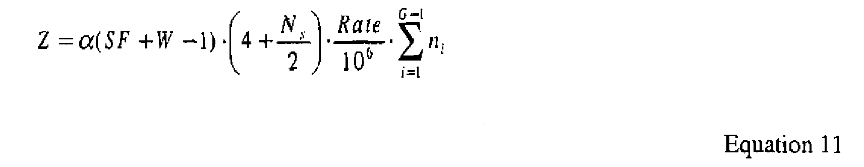
The complexity of converting soft to hard decisions is negligible. - There are several well-known techniques to solve the matrix inversion of JD. To illustrate the complexity, an approach using a very efficient approximate Cholesky factor algorithm with negligible loss in performance as compared to the exact Cholesky factor algorithm was used. The same algorithm can be employed to solve group-wise JD. The complexity of the full JD and the SIC-JD for the 3GPP UTRA TDD system is shown in Table 1. Table I compares their complexity for various group sizes. It can be seen that as K increases or as the group size decreases the complexity advantage of the SIC-JD over the full JD increases. The complexity for
group size 1, of the SIC-LSE, varies linearly with K and is 33% that of the full JD for K = 16. Note that maximum number of bursts in the UTRA TDD system is 16. The complexity advantage of the SIC-JD over full JD will be even more pronounced when the exact Cholesky decomposition is employed. Exact Cholesky decomposition's complexity exhibits a stronger dependence on K, leading to more savings as the dimension of the JD is reduced via SIC-JD.Table 1 Total number of bursts Complexity of the SIC-JD expressed as a percentage of the complexity of the single-step JD of all K bursts K groups of size 1 each (SIC-LSE)K / 2 groups of size 2 eachK / 4 groups of size 4 eachK / 8 groups of size 8 each8 63% 67% 76% 100% 16 33% 36% 41% 57% - As shown in Table 1, when the number and size of codes is made completely adaptive on an observation interval-by-observation interval basis, the SIC-JD provides savings, on average, over full JD. Since, on average, all bursts do not arrive at the receiver with equal power, depending upon the grouping threshold, the size of the groups will be less then the total number of arriving bursts. In addition, a reduction in peak complexity is also possible if the maximum allowed group size is hard-limited to be less than the maximum possible number of bursts. Such a scheme leads to some degradation in performance when the number of bursts arriving at the receiver with the roughly the same power exceeds the maximum allowed group size. Accordingly, SIC-JD provides a mechanism to trade-off performance with peak complexity or required peak processing power.
Claims (39)
- A method for use in a receiver for receiving a plurality of data signals transmitted over a shared spectrum in a time slot in a time division duplex communication system using code division multiple access, the method comprising:receiving a combined signal over the shared spectrum in the time slot;estimating a received power level for each data signal;selectively grouping data signals of the plurality of data signals into groups where the received power level of the data signals is within a certain threshold, the certain threshold is adjusted to achieve a desired bit error rate at the receiver;separately detecting data within each group for that group's data signals; andestimating the received power level for each data signal is based on in part apriori knowledge at the receiver.
- The method of claim 1, wherein the estimating the received power level for each data signal is based on in part a power level of a training sequence associated with each data signal.
- The method of claim 1, wherein the estimating the received power level for each data signal is performed using a bank of matched filters, each matched filter matched to a code of a respective one of the data signals.
- The method of claim 1, wherein the certain threshold power level is two decibel.
- The method of claim 1, wherein the certain threshold power level is one decibel.
- The method of claim 1, wherein the bit error rate is in a range of 1% to 10%.
- The method of claim 1, further comprising forcing all of the data signals into a single group to override the step of selectively grouping.
- The method of claim 1 further comprising forcibly grouping each data signal into its own group to override the step of selectively grouping.
- A receiver for receiving a plurality of data signals transmitted over a shared spectrum in a time slot in a time division duplex communication system using code division multiple access, the receiver being arranged for:receiving a combined signal over the shared spectrum in the time slot;estimating a received power level for each data signal;selectively grouping data signals of the plurality of data signals into groups where the received power level of the data signals is within a certain threshold, the certain threshold is adjusted to achieve a desired bit error rate at the receiver;separately detecting data within each group for that group's data signals; andestimating the received power level for each data signal is based on in part a priori knowledge at the receiver.
- The receiver of claim 9, further arranged for estimating the received power level for each data signal is based on in part a power level of a training sequence associated with each data signal.
- The receiver of claim 9, further arranged for estimating the received power level for each data signal by using a bank of matched filters, each matched filter matched to a code of a respective one of the data signals.
- The receiver of claim 9, wherein the certain threshold power level is two decibel.
- The receiver of claim 9, wherein the certain threshold power level is one decibel.
- The receiver of claim 9, wherein the bit error rate is in a range of 1% to 10%.
- The receiver of claim 9, further arranged for forcing all of the data signals into a single group to override the step of selectively grouping.
- The receiver of claim 9, further arranged for forcibly grouping each data signal into its own group to override the step of selectively grouping.
- A user equipment comprising a receiver according to any one of claims 9-16.
- A base station comprising a receiver according to any one of claims 9-16.
- A method for use in receiving a plurality of data signals transmitted over a shared spectrum in a time slot in a time division duplex communication system using code division multiple access, the method comprising:receiving a combined signal over the shared spectrum in the time slot;grouping the plurality of data signals into a plurality of groups;match filtering the combined signal based on in part symbol responses associated with the data signals of one of the groups;jointly detecting data from each data signal in the one group;constructing an interference signal based on in part the one group detected data;subtracting the constructed interference signal from the combined signal; anddetermining data from a group other than the one group by processing the subtracted signal.
- The method of claim 19 wherein the jointly detecting is performed using least squares estimation.
- The method of claim 19 wherein the jointly detecting is performed using minimum mean square error estimation.
- A method for use in receiving a plurality of data signals transmitted over a shared spectrum in a time slot in a time division duplex communication system using code division multiple access, the method comprising:(a) receiving a combined signal as an input signal over the shared spectrum in the time slot;(b) grouping the plurality of data signals into a plurality of groups, at least one of the groups having a plurality of data signals;(c) match filtering the input signal based on in part symbol responses associated with each data signal of a first group of the groups;(d) jointly detecting data from each data signal in the first group;(e) constructing an interference signal based on in part the first group detected data;(f) subtracting the constructed interference signal from the input signal as an input signal for subsequent processing;(g) match filtering the subtracted signal based on in part symbol responses associated with the data signal of a subsequent group of the groups;(h) jointly detecting data from each data signal in the subsequent group; and(i) successively repeating steps (e) through (h) for remaining groups of the plurality of groups where, for each remaining group, the subsequent group acts as the first group for that remaining group and that remaining group acts as the subsequent group.
- A method for use in a receiver for receiving a plurality of data signals transmitted over a shared spectrum in a time slot in a time division duplex communication system using code division multiple access, the method comprising:receiving a combined signal over the shared spectrum in the time slot;estimating a received power level for each data signal;selectively grouping data signals of the plurality of data signals based on in part the received power level of the data signals into at least one group; andseparately detecting data within each group for that group's data signals.
- The method of claim 23 wherein the estimating the received power level for each data signal is based on in part apriori knowledge at the receiver.
- The method of claim 23 wherein the estimating the received power level for each data signal is based on in part a power level of a training sequence associated with each data signal.
- The method of claim 23 wherein the estimating the received power level for each data signal is performed using a bank of matched filters, each matched filter matched to a code of a respective one of the data signals.
- The method of claim 23 wherein the selectively grouping data signals groups data signals within a certain threshold power level into a group.
- The method of claim 27 wherein the certain threshold power level is one decibel.
- The method of claim 27 wherein the certain threshold is adjusted to achieve a desired bit error rate at the receiver.
- The method of claim 23 further comprising forcing all of the data signals into a single group to override the step of selectively grouping.
- The method of claim 23 further comprising forcibly grouping each data signal into its own group to override the step of selectively grouping.
- A receiver for use in a time division duplex communication system using code division multiple access, the system communicating using multiple communication bursts in a time slot, the receiver comprising:an antenna for receiving radio frequency signals including the multiple communication bursts,a demodulator for demodulating radio frequency signals to produce a baseband signal;a channel estimation device for estimating a channel response for the bursts;a successive interference cancellation joint detection (SIC-JD) device comprising:a first joint detection block for detecting data within the baseband signal for a first group of bursts of the multiple bursts;a first interference construction block for constructing an estimate of interference of the first group bursts;a subtractor for subtracting the first group interference from the baseband signal; anda second joint detection block for detecting data within the subtracted signal for a second group of bursts of the multiple bursts.
- The receiver of claim 32 wherein the SIC.JD device further comprises:a plurality of additional joint detection blocks for detecting data for additional groups of bursts of the multiple bursts.
- The receiver of claim 32 wherein the SIC-JD device further comprises:a first matched filter for processing the baseband signal to match symbol responses of the data signals in the first group; anda second matched filter for processing the subtracted signal to match symbol responses of the data signals in the second group.
- The receiver of claim 32 wherein an output of the first and second joint detection blocks are soft symbols, the SIC-JD device further comprising a first and second soft to hard decision block for converting the first and second joint detection block outputs into hard symbols.
- A device for use in a receiver of a time division duplex communication system using code division multiple access, the system communicating using multiple communication bursts in a time slot, the device comprising:an input configured to receive a baseband signal associated with received bursts within a time slot;a first joint detection block for detecting data within the baseband signal for a first group of bursts of the received bursts;a first interference construction block for constructing an estimate of interference of the first group bursts;a subtractor for subtracting the first group interference from the baseband signal; anda second joint detection block for detecting data within the subtracted signal for a second group of bursts of the received bursts.
- The device of claim 3'6 further comprising additional joint detection blocks for detecting data for additional groups of bursts of the multiple bursts.
- The device of claim 3 6 further comprising:a first matched filter for processing the baseband signal to match symbol responses of the received bursts of the first group; anda second matched filter for processing the subtracted signal to match symbol responses of the received bursts of the second group.
- The device of claim 3 6 wherein an output of the first and second joint detection blocks are soft symbols, the device further comprising a first and second soft to hard decision block converting the first and second joint detection block outputs into hard symbols.
Applications Claiming Priority (3)
| Application Number | Priority Date | Filing Date | Title |
|---|---|---|---|
| US18968000P | 2000-03-15 | 2000-03-15 | |
| US20770000P | 2000-05-26 | 2000-05-26 | |
| EP01911077A EP1264415B1 (en) | 2000-03-15 | 2001-02-21 | Multi-user detection using an adaptive combination of joint detection and successive interference cancellation |
Related Parent Applications (1)
| Application Number | Title | Priority Date | Filing Date |
|---|---|---|---|
| EP01911077A Division EP1264415B1 (en) | 2000-03-15 | 2001-02-21 | Multi-user detection using an adaptive combination of joint detection and successive interference cancellation |
Publications (2)
| Publication Number | Publication Date |
|---|---|
| EP1681775A2 true EP1681775A2 (en) | 2006-07-19 |
| EP1681775A3 EP1681775A3 (en) | 2008-12-03 |
Family
ID=36581476
Family Applications (1)
| Application Number | Title | Priority Date | Filing Date |
|---|---|---|---|
| EP06111278A Withdrawn EP1681775A3 (en) | 2000-03-15 | 2001-02-21 | Multi-user detection using an adaptive combination of joint detection and successive interference cancellation |
Country Status (1)
| Country | Link |
|---|---|
| EP (1) | EP1681775A3 (en) |
Cited By (16)
| Publication number | Priority date | Publication date | Assignee | Title |
|---|---|---|---|---|
| WO2009108586A2 (en) * | 2008-02-27 | 2009-09-03 | Qualcomm Incorporated | Coherent single antenna interference cancellation for gsm/gprs/edge |
| CN101154959B (en) * | 2006-09-25 | 2010-12-08 | 中兴通讯股份有限公司 | Method for detecting system self-interference in time division duplex wireless honeycomb communication network |
| US8503591B2 (en) | 2008-08-19 | 2013-08-06 | Qualcomm Incorporated | Enhanced geran receiver using channel input beamforming |
| US8509293B2 (en) | 2008-08-19 | 2013-08-13 | Qualcomm Incorporated | Semi-coherent timing propagation for GERAN multislot configurations |
| US8619928B2 (en) | 2009-09-03 | 2013-12-31 | Qualcomm Incorporated | Multi-stage interference suppression |
| US8675796B2 (en) | 2008-05-13 | 2014-03-18 | Qualcomm Incorporated | Interference cancellation under non-stationary conditions |
| US8787509B2 (en) | 2009-06-04 | 2014-07-22 | Qualcomm Incorporated | Iterative interference cancellation receiver |
| US8831149B2 (en) | 2009-09-03 | 2014-09-09 | Qualcomm Incorporated | Symbol estimation methods and apparatuses |
| US8995417B2 (en) | 2008-06-09 | 2015-03-31 | Qualcomm Incorporated | Increasing capacity in wireless communication |
| US9055545B2 (en) | 2005-08-22 | 2015-06-09 | Qualcomm Incorporated | Interference cancellation for wireless communications |
| US9071344B2 (en) | 2005-08-22 | 2015-06-30 | Qualcomm Incorporated | Reverse link interference cancellation |
| US9160577B2 (en) | 2009-04-30 | 2015-10-13 | Qualcomm Incorporated | Hybrid SAIC receiver |
| US9237515B2 (en) | 2008-08-01 | 2016-01-12 | Qualcomm Incorporated | Successive detection and cancellation for cell pilot detection |
| US9277487B2 (en) | 2008-08-01 | 2016-03-01 | Qualcomm Incorporated | Cell detection with interference cancellation |
| US9509452B2 (en) | 2009-11-27 | 2016-11-29 | Qualcomm Incorporated | Increasing capacity in wireless communications |
| US9673837B2 (en) | 2009-11-27 | 2017-06-06 | Qualcomm Incorporated | Increasing capacity in wireless communications |
Citations (2)
| Publication number | Priority date | Publication date | Assignee | Title |
|---|---|---|---|---|
| DE19616828A1 (en) | 1996-04-26 | 1997-11-06 | Siemens Ag | Received mixed signal separation method esp. for mobile telephone system using different or common channels for different subscriber signals |
| US5933423A (en) | 1994-07-04 | 1999-08-03 | Nokia Telecommunications Oy | Reception method, and a receiver |
Family Cites Families (1)
| Publication number | Priority date | Publication date | Assignee | Title |
|---|---|---|---|---|
| CN1078988C (en) * | 1995-06-13 | 2002-02-06 | Ntt移动通信网株式会社 | CDMA demodulator |
-
2001
- 2001-02-21 EP EP06111278A patent/EP1681775A3/en not_active Withdrawn
Patent Citations (2)
| Publication number | Priority date | Publication date | Assignee | Title |
|---|---|---|---|---|
| US5933423A (en) | 1994-07-04 | 1999-08-03 | Nokia Telecommunications Oy | Reception method, and a receiver |
| DE19616828A1 (en) | 1996-04-26 | 1997-11-06 | Siemens Ag | Received mixed signal separation method esp. for mobile telephone system using different or common channels for different subscriber signals |
Cited By (22)
| Publication number | Priority date | Publication date | Assignee | Title |
|---|---|---|---|---|
| US9071344B2 (en) | 2005-08-22 | 2015-06-30 | Qualcomm Incorporated | Reverse link interference cancellation |
| US9055545B2 (en) | 2005-08-22 | 2015-06-09 | Qualcomm Incorporated | Interference cancellation for wireless communications |
| CN101154959B (en) * | 2006-09-25 | 2010-12-08 | 中兴通讯股份有限公司 | Method for detecting system self-interference in time division duplex wireless honeycomb communication network |
| US7933256B2 (en) | 2008-02-27 | 2011-04-26 | Qualcomm Incorporated | Coherent single antenna interference cancellation for GSM/GPRS/EDGE |
| EP2330770A1 (en) * | 2008-02-27 | 2011-06-08 | QUALCOMM Incorporated | Coherent single antenna interference cancellation for GSM/GPRS/edge |
| RU2461135C2 (en) * | 2008-02-27 | 2012-09-10 | Квэлкомм Инкорпорейтед | Coherent single antenna interference compensation for gsm/gprs/edge |
| WO2009108586A2 (en) * | 2008-02-27 | 2009-09-03 | Qualcomm Incorporated | Coherent single antenna interference cancellation for gsm/gprs/edge |
| US8675796B2 (en) | 2008-05-13 | 2014-03-18 | Qualcomm Incorporated | Interference cancellation under non-stationary conditions |
| US8995417B2 (en) | 2008-06-09 | 2015-03-31 | Qualcomm Incorporated | Increasing capacity in wireless communication |
| US9408165B2 (en) | 2008-06-09 | 2016-08-02 | Qualcomm Incorporated | Increasing capacity in wireless communications |
| US9014152B2 (en) | 2008-06-09 | 2015-04-21 | Qualcomm Incorporated | Increasing capacity in wireless communications |
| US9277487B2 (en) | 2008-08-01 | 2016-03-01 | Qualcomm Incorporated | Cell detection with interference cancellation |
| US9237515B2 (en) | 2008-08-01 | 2016-01-12 | Qualcomm Incorporated | Successive detection and cancellation for cell pilot detection |
| US8509293B2 (en) | 2008-08-19 | 2013-08-13 | Qualcomm Incorporated | Semi-coherent timing propagation for GERAN multislot configurations |
| US8503591B2 (en) | 2008-08-19 | 2013-08-06 | Qualcomm Incorporated | Enhanced geran receiver using channel input beamforming |
| US9160577B2 (en) | 2009-04-30 | 2015-10-13 | Qualcomm Incorporated | Hybrid SAIC receiver |
| US8787509B2 (en) | 2009-06-04 | 2014-07-22 | Qualcomm Incorporated | Iterative interference cancellation receiver |
| US8831149B2 (en) | 2009-09-03 | 2014-09-09 | Qualcomm Incorporated | Symbol estimation methods and apparatuses |
| US8619928B2 (en) | 2009-09-03 | 2013-12-31 | Qualcomm Incorporated | Multi-stage interference suppression |
| US9509452B2 (en) | 2009-11-27 | 2016-11-29 | Qualcomm Incorporated | Increasing capacity in wireless communications |
| US9673837B2 (en) | 2009-11-27 | 2017-06-06 | Qualcomm Incorporated | Increasing capacity in wireless communications |
| US10790861B2 (en) | 2009-11-27 | 2020-09-29 | Qualcomm Incorporated | Increasing capacity in wireless communications |
Also Published As
| Publication number | Publication date |
|---|---|
| EP1681775A3 (en) | 2008-12-03 |
Similar Documents
| Publication | Publication Date | Title |
|---|---|---|
| EP1264415B1 (en) | Multi-user detection using an adaptive combination of joint detection and successive interference cancellation | |
| US8553820B2 (en) | Groupwise successive interference cancellation for block transmission with reception diversity | |
| Patel et al. | Analysis of a simple successive interference cancellation scheme in a DS/CDMA system | |
| EP1358718B1 (en) | Low complexity data detection using fast fourier transform of channel correlation matrix | |
| EP1681775A2 (en) | Multi-user detection using an adaptive combination of joint detection and successive interference cancellation | |
| CA2492677A1 (en) | Scaling using gain factors for use in data detection for wireless code division multiple access communication systems | |
| EP1875623A2 (en) | Joint detector in a code division multiple access radio receiver | |
| US7161972B2 (en) | Method and apparatus for downlink joint detection in a communication system | |
| CN100492932C (en) | Multi-user detection using an adaptive combination of joint detection and successive interference cancellation | |
| Irmer et al. | Nonlinear chip-level multiuser transmission for TDD-CDMA with frequency-selective MIMO channels | |
| Misra et al. | Multi-user Detection using a Combination of Linear Sequence Estimation and Successive Interference Cancellation | |
| Huayu et al. | Applying V-BLAST detection algorithms into TDD-CDMA | |
| EP1693971A2 (en) | Low complexity data detection using fast fourier transform of channel correlation matrix | |
| Zhou et al. | Chip-interleaved block-spread CDMA for the downlink with inter-cell interference and soft hand-off |
Legal Events
| Date | Code | Title | Description |
|---|---|---|---|
| PUAI | Public reference made under article 153(3) epc to a published international application that has entered the european phase |
Free format text: ORIGINAL CODE: 0009012 |
|
| 17P | Request for examination filed |
Effective date: 20060316 |
|
| AC | Divisional application: reference to earlier application |
Ref document number: 1264415 Country of ref document: EP Kind code of ref document: P |
|
| AK | Designated contracting states |
Kind code of ref document: A2 Designated state(s): AT BE BG CH CY CZ DE DK EE ES FI FR GB GR HU IE IS IT LI LT LU LV MC NL PL PT RO SE SI SK TR |
|
| AX | Request for extension of the european patent |
Extension state: AL BA HR MK YU |
|
| RAP1 | Party data changed (applicant data changed or rights of an application transferred) |
Owner name: INTERDIGITAL TECHNOLOGY CORPORATION |
|
| PUAL | Search report despatched |
Free format text: ORIGINAL CODE: 0009013 |
|
| AK | Designated contracting states |
Kind code of ref document: A3 Designated state(s): AT BE BG CH CY CZ DE DK EE ES FI FR GB GR HU IE IS IT LI LT LU LV MC NL PL PT RO SE SI SK TR |
|
| AX | Request for extension of the european patent |
Extension state: AL BA HR MK YU |
|
| 17Q | First examination report despatched |
Effective date: 20090604 |
|
| AKX | Designation fees paid |
Designated state(s): AT BE BG CH CY CZ DE DK EE ES FI FR GB GR HU IE IS IT LI LT LU LV MC NL PL PT RO SE SI SK TR |
|
| RBV | Designated contracting states (corrected) |
Designated state(s): AT BE CH CY DE DK ES FI FR GB GR IE IT LI LU MC NL PT SE TR |
|
| RAP1 | Party data changed (applicant data changed or rights of an application transferred) |
Owner name: INTERDIGITAL TECHNOLOGY CORPORATION |
|
| STAA | Information on the status of an ep patent application or granted ep patent |
Free format text: STATUS: THE APPLICATION IS DEEMED TO BE WITHDRAWN |
|
| 18D | Application deemed to be withdrawn |
Effective date: 20160712 |