EP1681731A1 - Compact superconducting current limiting component in coil configuration with low inductance - Google Patents
Compact superconducting current limiting component in coil configuration with low inductance Download PDFInfo
- Publication number
- EP1681731A1 EP1681731A1 EP05300030A EP05300030A EP1681731A1 EP 1681731 A1 EP1681731 A1 EP 1681731A1 EP 05300030 A EP05300030 A EP 05300030A EP 05300030 A EP05300030 A EP 05300030A EP 1681731 A1 EP1681731 A1 EP 1681731A1
- Authority
- EP
- European Patent Office
- Prior art keywords
- coil
- current limiting
- limiting component
- superconducting current
- htsc
- Prior art date
- Legal status (The legal status is an assumption and is not a legal conclusion. Google has not performed a legal analysis and makes no representation as to the accuracy of the status listed.)
- Withdrawn
Links
- 239000002887 superconductor Substances 0.000 claims abstract description 86
- 239000000463 material Substances 0.000 claims abstract description 66
- 239000000919 ceramic Substances 0.000 claims abstract description 29
- 239000010409 thin film Substances 0.000 claims description 12
- 238000000034 method Methods 0.000 claims description 11
- 239000004020 conductor Substances 0.000 claims description 10
- 229910052791 calcium Inorganic materials 0.000 claims description 7
- 229910052727 yttrium Inorganic materials 0.000 claims description 7
- 229910002480 Cu-O Inorganic materials 0.000 claims description 6
- 208000036822 Small cell carcinoma of the ovary Diseases 0.000 claims description 6
- 229910052797 bismuth Inorganic materials 0.000 claims description 6
- 238000005520 cutting process Methods 0.000 claims description 6
- 238000004519 manufacturing process Methods 0.000 claims description 6
- 229910052751 metal Inorganic materials 0.000 claims description 6
- 239000002184 metal Substances 0.000 claims description 6
- 201000005292 ovarian small cell carcinoma Diseases 0.000 claims description 6
- 238000002360 preparation method Methods 0.000 claims description 6
- 229910052745 lead Inorganic materials 0.000 claims description 5
- 229910052788 barium Inorganic materials 0.000 claims description 3
- 229910052765 Lutetium Inorganic materials 0.000 claims description 2
- 229910052779 Neodymium Inorganic materials 0.000 claims description 2
- 229910052769 Ytterbium Inorganic materials 0.000 claims description 2
- 229910052746 lanthanum Inorganic materials 0.000 claims description 2
- 229910052761 rare earth metal Inorganic materials 0.000 claims description 2
- 238000010791 quenching Methods 0.000 description 15
- 239000010949 copper Substances 0.000 description 12
- 239000000203 mixture Substances 0.000 description 8
- 238000004804 winding Methods 0.000 description 8
- 239000000853 adhesive Substances 0.000 description 7
- 230000001070 adhesive effect Effects 0.000 description 7
- 230000005684 electric field Effects 0.000 description 7
- 230000000171 quenching effect Effects 0.000 description 7
- 229910052802 copper Inorganic materials 0.000 description 6
- 230000006698 induction Effects 0.000 description 6
- 230000001939 inductive effect Effects 0.000 description 6
- RYGMFSIKBFXOCR-UHFFFAOYSA-N Copper Chemical compound [Cu] RYGMFSIKBFXOCR-UHFFFAOYSA-N 0.000 description 5
- 150000001875 compounds Chemical class 0.000 description 5
- 230000001965 increasing effect Effects 0.000 description 5
- 125000006850 spacer group Chemical group 0.000 description 5
- 229910021521 yttrium barium copper oxide Inorganic materials 0.000 description 5
- QVGXLLKOCUKJST-UHFFFAOYSA-N atomic oxygen Chemical compound [O] QVGXLLKOCUKJST-UHFFFAOYSA-N 0.000 description 4
- TZCXTZWJZNENPQ-UHFFFAOYSA-L barium sulfate Chemical compound [Ba+2].[O-]S([O-])(=O)=O TZCXTZWJZNENPQ-UHFFFAOYSA-L 0.000 description 4
- 238000013461 design Methods 0.000 description 4
- 229910052760 oxygen Inorganic materials 0.000 description 4
- 239000001301 oxygen Substances 0.000 description 4
- 229910052712 strontium Inorganic materials 0.000 description 4
- 229910000881 Cu alloy Inorganic materials 0.000 description 3
- 238000005266 casting Methods 0.000 description 3
- 238000001816 cooling Methods 0.000 description 3
- 230000006378 damage Effects 0.000 description 3
- 239000012777 electrically insulating material Substances 0.000 description 3
- 238000010438 heat treatment Methods 0.000 description 3
- 238000002156 mixing Methods 0.000 description 3
- 238000013021 overheating Methods 0.000 description 3
- 239000000758 substrate Substances 0.000 description 3
- IJGRMHOSHXDMSA-UHFFFAOYSA-N Atomic nitrogen Chemical compound N#N IJGRMHOSHXDMSA-UHFFFAOYSA-N 0.000 description 2
- 229920002430 Fibre-reinforced plastic Polymers 0.000 description 2
- 229910020073 MgB2 Inorganic materials 0.000 description 2
- PPBRXRYQALVLMV-UHFFFAOYSA-N Styrene Chemical compound C=CC1=CC=CC=C1 PPBRXRYQALVLMV-UHFFFAOYSA-N 0.000 description 2
- 238000001354 calcination Methods 0.000 description 2
- 239000011248 coating agent Substances 0.000 description 2
- 238000000576 coating method Methods 0.000 description 2
- 230000007423 decrease Effects 0.000 description 2
- 239000004744 fabric Substances 0.000 description 2
- 238000010304 firing Methods 0.000 description 2
- 239000011810 insulating material Substances 0.000 description 2
- 239000000155 melt Substances 0.000 description 2
- 229910044991 metal oxide Inorganic materials 0.000 description 2
- 150000004706 metal oxides Chemical class 0.000 description 2
- 239000004033 plastic Substances 0.000 description 2
- 229920003023 plastic Polymers 0.000 description 2
- 229910052702 rhenium Inorganic materials 0.000 description 2
- 238000012216 screening Methods 0.000 description 2
- 230000006641 stabilisation Effects 0.000 description 2
- 239000007858 starting material Substances 0.000 description 2
- 230000007704 transition Effects 0.000 description 2
- OKTJSMMVPCPJKN-UHFFFAOYSA-N Carbon Chemical compound [C] OKTJSMMVPCPJKN-UHFFFAOYSA-N 0.000 description 1
- 229910000831 Steel Inorganic materials 0.000 description 1
- 238000000137 annealing Methods 0.000 description 1
- 230000015572 biosynthetic process Effects 0.000 description 1
- 229910052799 carbon Inorganic materials 0.000 description 1
- 150000004649 carbonic acid derivatives Chemical class 0.000 description 1
- 229910052923 celestite Inorganic materials 0.000 description 1
- 238000009750 centrifugal casting Methods 0.000 description 1
- 239000002131 composite material Substances 0.000 description 1
- 238000010276 construction Methods 0.000 description 1
- 239000002826 coolant Substances 0.000 description 1
- 238000011161 development Methods 0.000 description 1
- 239000003822 epoxy resin Substances 0.000 description 1
- -1 etcetera Substances 0.000 description 1
- 239000011151 fibre-reinforced plastic Substances 0.000 description 1
- 239000010408 film Substances 0.000 description 1
- 230000004907 flux Effects 0.000 description 1
- 239000003365 glass fiber Substances 0.000 description 1
- 238000009413 insulation Methods 0.000 description 1
- 239000004922 lacquer Substances 0.000 description 1
- 239000007788 liquid Substances 0.000 description 1
- 239000000696 magnetic material Substances 0.000 description 1
- 238000005297 material degradation process Methods 0.000 description 1
- 238000002844 melting Methods 0.000 description 1
- 230000008018 melting Effects 0.000 description 1
- 150000002739 metals Chemical class 0.000 description 1
- 238000003801 milling Methods 0.000 description 1
- 229910052757 nitrogen Inorganic materials 0.000 description 1
- 230000035699 permeability Effects 0.000 description 1
- 239000011505 plaster Substances 0.000 description 1
- 229920000647 polyepoxide Polymers 0.000 description 1
- 230000002028 premature Effects 0.000 description 1
- 238000012545 processing Methods 0.000 description 1
- 230000035484 reaction time Effects 0.000 description 1
- 238000011084 recovery Methods 0.000 description 1
- 229920005989 resin Polymers 0.000 description 1
- 239000011347 resin Substances 0.000 description 1
- 238000000926 separation method Methods 0.000 description 1
- 238000005245 sintering Methods 0.000 description 1
- 239000007787 solid Substances 0.000 description 1
- 238000011105 stabilization Methods 0.000 description 1
- 230000000087 stabilizing effect Effects 0.000 description 1
- 239000010959 steel Substances 0.000 description 1
- 239000000126 substance Substances 0.000 description 1
- 238000012360 testing method Methods 0.000 description 1
- 239000004753 textile Substances 0.000 description 1
Images
Classifications
-
- H—ELECTRICITY
- H10—SEMICONDUCTOR DEVICES; ELECTRIC SOLID-STATE DEVICES NOT OTHERWISE PROVIDED FOR
- H10N—ELECTRIC SOLID-STATE DEVICES NOT OTHERWISE PROVIDED FOR
- H10N60/00—Superconducting devices
- H10N60/30—Devices switchable between superconducting and normal states
-
- H—ELECTRICITY
- H01—ELECTRIC ELEMENTS
- H01F—MAGNETS; INDUCTANCES; TRANSFORMERS; SELECTION OF MATERIALS FOR THEIR MAGNETIC PROPERTIES
- H01F6/00—Superconducting magnets; Superconducting coils
- H01F6/02—Quenching; Protection arrangements during quenching
-
- H—ELECTRICITY
- H01—ELECTRIC ELEMENTS
- H01F—MAGNETS; INDUCTANCES; TRANSFORMERS; SELECTION OF MATERIALS FOR THEIR MAGNETIC PROPERTIES
- H01F6/00—Superconducting magnets; Superconducting coils
- H01F2006/001—Constructive details of inductive current limiters
-
- H—ELECTRICITY
- H01—ELECTRIC ELEMENTS
- H01F—MAGNETS; INDUCTANCES; TRANSFORMERS; SELECTION OF MATERIALS FOR THEIR MAGNETIC PROPERTIES
- H01F6/00—Superconducting magnets; Superconducting coils
- H01F6/06—Coils, e.g. winding, insulating, terminating or casing arrangements therefor
Definitions
- the present invention relates to a superconducting current limiting component, particularly to a resistive ceramic high-temperature superconducting current limiting component which is self-triggering.
- Superconductors in particular ceramic high-temperature superconductors, offer a great potential as fault current limiters which enable rapid and effective current limitation, automatic recovery, negligible impedance during normal operation and application at high voltage.
- the superconductor in case of fault the current flowing through the superconductor material exceeds the critical current of the superconductor material due to large surge current and the superconducting material undergoes transition from the superconducting state to the normal conducting state. This transition is also termed "quenching". For good operation, after the current limiting event the superconductor should have the capability to return to its superconducting state.
- inductive current limiters When applied with fault current, the inductive current limiter provides a high impedance which limits the fault current below a threshold level.
- US-A-5,140,290 discloses a device for inductive current limiting of alternating current, in which the current to be limited flows through an induction coil made of copper. A hollow cylinder of a high temperature superconducting material is arranged in the interior of this coil, and a soft magnetic material with high permeability is arranged concentrically inside. In normal operation (rated current) the superconductivity of the hollow cylinder shields the magnetic field of the induction coil completely from the core and impedance of the induction coil is maintained at a very low level. When a fault current flows through the induction coil the superconductivity of the hollow cylinder body disappears and the impedance of the induction coil reaches its maximum current-limiting value.
- the superconducting material of which a superconductor body is made is not completely homogeneous throughout the superconductor body, so that the superconductor properties such as critical current density can be different at different regions of the superconductor body. Consequently, in case of fault current some regions become already resistive whereas other regions still remain superconducting. Due to the still superconducting regions high current flows through the superconductor body leading to a high temperature increase in the already resistive regions and causing burn out in these regions.
- the electrically conducting material for the shunt is a metal such as copper or copper alloy.
- resistive current limiters which are composed of a cylindrical tubular superconductor body having a stripe of electrically conducting metal coated on its outer surface in parallel to the longitudinal axis and reaching from one end of the cylindrical tubular body to its other end.
- superconductor components related to such configuration are referred to in WO 00/8657.
- a resistive high-temperature superconductor current limiter wherein the superconductor component has the shape of a bifilar spiral. On one face of the bifilar spiral made of the superconductor material all along its winding a metal coating is applied for the shunt.
- both the shunt as well as the superconductor body have nearly the same length.
- the necessary minimum length of the current limiter at a given voltage is defined by the maximum strength of the electrical field which can be applied along the normal conducting shunt during short circuit. If the electrical field acting on the shunt during short circuit exceeds the maximum value overheating of the shunt occurs with temperatures exceeding the melting point of the shunt material and, consequently, the shunt melts.
- the maximum electrical field applicable to commonly used shunt materials is about 1 V/cm. That is, if a voltage of 10 kV is applied to the current limiter the length of the superconductor body has to be about 100 m in order to limit the electrical field to which the shunt is subjected during fault event to about 1 V/cm.
- a superconducting current limiting device wherein magnetic field generating means are provided for generating and applying, during normal operation in the superconducting state, a magnetic field to the superconductor element in order to hold the current density below the critical current density.
- the magnetic field is adjusted, that is, increased to reduce the critical current density in order to bring the superconductor element to its resistive state.
- the superconductor element is positioned within a shunt coil which is connected in parallel to the superconductor element. In fault event excess current is forced into the shunt coil and the current flow in the shunt coil generates a magnetic field which acts on the superconductor element and decreases the critical current density, thereby assisting quenching.
- superconductor element a thin film superconductor is disclosed on a semiconducting substrate. According to the figure layers of superconductor thin films and layers of the substrate alternate, that is the superconductor element is a stack of layers of superconductor thin films and layers of substrates. However, further details as to the specific constructions of this embodiment, in particular of the resulting shape of the superconductor element, are not given.
- the object of the present invention to provide a superconducting current limiting component with a shunt which makes possible to build up sufficiently high electrical field along the superconducting material during the short circuit, within a short time, which can be produced in a simple and cheap way, and which is capable to create a magnetic field high enough to bring the superconductor material to homogenous quench in the short circuit case. Further, it was the object of the present invention to provide a superconducting current limiting component with a space saving low inductive element design which is easily to be insulated even with respect to high voltages.
- a superconducting current limiting component comprising a coil made of ceramic high temperature superconductor material.
- a second coil is applied which acts as a shunt and generates the desired magnetic field.
- a hollow cylindrical body of ceramic high temperatures superconductor material can be introduced into the first superconducting coil.
- a support element for stabilization can be provided, e.g. between the first coil and the hollow cylindrical body made of a ceramic high temperature superconductor material.
- the first coil made of a ceramic high temperature superconductor material is also referred to as “htsc coil” and the hollow cylindrical body made of a ceramic high temperature superconductor material as “htsc tube”.
- the superconductor length can be significantly increased as compared to the superconductor length of the conventional current limiting device having a tube shaped configuration.
- the superconductor length can be increased to the 1 0-fold with the same component height.
- the resistance appearing in the htsc coil due to the fault current causes a part of the current to by-pass into the shunt coil which is provided around the outer surface of the htsc coil and is connected electrically and physically in parallel with the htsc coil.
- the magnetic field associated with this current serves to bring the superconductor material in a uniform quench during the short circuit event and to avoid material degradation, for example, due to hot spot formation.
- the shunt of the present invention it is possible to build up high electrical fields of e.g. 1 to 10 V/cm or higher along the superconductor material during short circuit within the desired short circuit time of 100 ms, however, which can be also more or less.
- the superconducting current limiting component of the present invention is self-triggering, which means, that the current limiting component has the capability of detecting and limiting fault current without active or external control.
- htsc tube hollow cylindrical body of ceramic high temperature superconductor material
- the htsc tube is dimensioned so that the htsc tube becomes resistive simultaneously or almost simultaneously with the quench of the htsc coil in default case when the current exceeds the critical current.
- the superconductivity of the htsc tube and, thus, the screening of the magnetic field disappears with the consequence that within the htsc coil inductive impedance is generated.
- the inductive impedance of the htsc coil acts as an additional resistance which contributes to the ohmic resistance in the htsc coil due to quenching and further lowers the short circuit current.
- the present invention may include any desired ceramic superconductor.
- Typical examples comprise oxide superconductors based on Bi-Ae-Cu-O, (Bi, Pb)-Ae-Cu-O, (Y, RE)-Ae-Cu-O or MgB2.
- Ae means at least one alkaline earth element, particularly, Ba, Ca and/or Sr.
- RE means at least one rare earth element, particularly Y or a combination of 2 or more of the elements Y, La, Lu, Sc, Sm, Nd or Yb.
- the superconductor of both, coil and tube can be made from ceramic bulk materials, thick films or thin films.
- preferred examples have a composition of or approximately of Bi 2 (Sr, Ca) 2 Cu 1 O x , (Bi, Pb) 2 (Sr, Ca) 2 Cu 1 O x , (Bi, Pb) 2 (Sr,Ca) 3 Cu 2 O x" , (Bi, Pb) 2 (Sr, Ca) 4 Cu 3 O x''' , (Y, Re) 1 Ba 2 Cu 3 O y , (Y, Re) 2 Ba 1 Cu 1 O y and MgB2.
- x, y and z stand for the appropriate oxygen content at which the respective compounds exhibit superconductivity.
- Especially suitable superconductors are those known by the reference BSCCO-2212, BSCCO-2223, wherein the numerical combinations 2212 and 2223 stands for the stoichiometric ratios of the elements Bi, Sr, Ca and Cu, in particular those, wherein part of Bi is substituted by Pb (also referred to B(Pb)SCCO-2212 and B(Pb)SCCO-2223); and that known by the reference YBCO-123, wherein the numerical combination 123 stands for the stoichiometric ratio of the elements Y, Ba and Cu.
- BSCCO-2212, B(Pb)SCCO-2212-material and YBCO-123 is used.
- BSCCO-2212 and B(Pb)SCCO-2212 is particularly suitable for ceramic bulk applications whereas YBCO-123 in thin films applications.
- BSCCO based superconductor materials may contain SrSO 4 and/or BaSO 4 as auxiliaries in an amount up to 20 percent by weight or when BaSO 4 is used, preferably only up to about 10 percent by weight.
- SrSO 4 and/or BaSO 4 as auxiliaries in an amount up to 20 percent by weight or when BaSO 4 is used, preferably only up to about 10 percent by weight.
- ceramic oxide high-temperature superconductors as, for example, referenced above and methods for their production are well known in the art.
- a summary of suitable high-temperature superconductors and production method thereof is given in WO 00/08657.
- YBCO-based superconductor bodies can be, for example, prepared by mixing the metal oxides, or compounds which are converted to metal oxides on heating, in suitable molar ratios, heating the mixture in the presence of oxygen to a temperature of between about 800 and about 1100 °C and slowly cooling the mixture in the presence of oxygen over a period of at least about 1 hour.
- BSCCO-based superconductor bodies can be prepared by mixing oxides or carbonates or mixtures of the respective elements in suitable mixing ratios. Subsequently, calcining is carried out at a temperature of about 700 to 900 °C for a period of about 2 to about 20 hours, the calcined mixture is ground, converted into the desired shape and sintered at a temperatures of about 800 to about 1100 °C in the semi- or fully-molten state.
- suitable BSCCO-based compounds and production methods thereof are found, for example, in EP-B-0 330 305 and EP-A-0 327 044, to which reference is expressly made here.
- superconductor bodies produced using a molten casting method in particular a centrifugal casting method as disclosed, for example, in DE-A-38 30 092, EP-A-0 451 532, EP-A-0 462 409 and EP-A-0 477 493, to which reference is likewise expressly made.
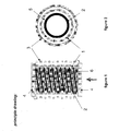
- figure 1 the current flow during normal operation within the htsc coil 1 and the htsc tube 2 in the superconducting state is shown by indicating the flow direction 6 of the current by arrows.
- the flow direction in figure 1 represents a snapshot because of AC current with changing flow direction.
- the htsc coil 1 is provided tightly around the htsc tube 2 from one end of the htsc tube 2 to the other end. Further, a normal conducting shunt 3 is wound around the outer surface of the htsc coil 1. At both ends of the current limiter electric contacts 4 are provided, wherein the normal conducting shunt 3 is connected to the electric contacts 4 at both ends.
- a support element 5 is provided which is arranged between the htsc tube 2 and the htsc coil 1.
- the same starting material for preparing the htsc coil 1 and the htsc tube 2 as used in the present invention preferably the same starting material, and, in particular, the same method can be applied. That is, preferably both the htsc coil 1 as well as the htsc tube 2 have the same chemical composition.
- the htsc coil 1 and the htsc tube 2 can be obtained starting from similar shaped bodies.
- a suitable starting material for a shaped body from which the htsc tube 2 and/or the htsc coil 1 according to the present invention can be obtained is a shaped body made from a pre-fired, sintered or post-annealed superconducting material.
- pre-firing such as e.g. calcining, sintering and optionally post-annealing, which may be carried out in a single firing operation or in several, possibly repeated, sub stages.
- a suitable starting geometry for the shaped body for the htsc tube 2 and htsc coil 1, respectively, is a rod or a tube with substantially cylindrical external geometry. Solid articles can be converted into corresponding hollow articles by mechanical processing.
- the shaped body should, if appropriate, have a maximally uniform thickness, in particular a cylindrical cavity concentric with the external surface.
- the tubular shaped body used for the htsc tube 2 is introduced into the hollow interior of the tubular shaped body intended for the htsc coil 1.
- the dimensions of the tubular shaped body are adjusted in an appropriate manner, such as external and internal diameters as well as the length of the tube.
- the volume of the tube should be as large as possible in order to minimize the inductance of the coil. That is, the interior cavity of the coil 1 should be filled by the htsc tube to the greatest possible extent.
- the external diameter of the htsc tube 2 should be a little bit smaller than the internal diameter of the tubular shaped body for the htsc coil 1 so that a gap is formed with a sufficient width for incorporating an electrically insulating material and/or adhesive and/or mechanical stabilisation (as referred to in more detail later on).
- an adhesive material used for connecting the htsc tube 2 to the tubular shaped body for the htsc coil 1 serves simultaneously as insulating material and/or support element.
- Adhesives can be used known to be suitable for low temperature applications, such as self - curing single - or multicomponent adhesive mixtures (e.g. styrene resin, epoxy resin) or composite material based on organic and/or inorganic adhesive and fabric components (e.g. textile fabric and plaster compound).
- the htsc coil 1 of the present invention can be obtained by cutting the desired coil profile into the jacket of the tubular shaped body for the htsc coil 1.
- cutting can be carried out by means of mechanical separation processes such as e.g. sawing, milling, boring, turning etc.
- Suitable methods for preparing coils from a tubular shaped body of high-temperature superconducting material are, for example, disclosed in WO 99/22386 to which reference is expressly made.
- the htsc coil extends from one end of the htsc tube 2 to the other end with at least one winding.
- the thread profile is not particularly limited but can be selected according to need, in particular taking into consideration the operation conditions of the final superconducting current limiting component. For example, depending on the actual operation currents of the final superconducting current limiting component the number of windings and pitch may vary to obtain the desired cross-section and/or nominal current.
- the shunt coil 3 wound around the outer surface of the htsc coil 1 typically is made of a normal conducting material, preferably a metal. Suitable metals are copper, copper alloys, steel, etcetera, copper being preferred. Further, also a suitable superconducting material can be used. Examples for suitable superconducting materials are tapes or wires, e.g. made of BSCCO-type material or YBCO thin films, (optionally with one or more additional and/or substitute element) as set out above with respect to the high temperature superconductor material for the htsc coil 1 and htsc tube 2.
- a high contact resistance or similar means should be provided, in particular, in case that the shunt coil 3 is made of a superconductor material.
- the shunt coil 3 can be made from a copper wire such as a lacquered wire or varnished wire wherein the wires are coated by a thin lacquer layer as commonly used in transformer applications.
- the inductance of the shunt coil should be as small as possible, in order to minimize its reaction time in the short circuit case.
- the wire can be wound directly onto the outer surface of the htsc coil 1.
- the shunt coil 3 can be wound around the htsc coil 1 at a distance.
- the gap, thus formed between the shunt coil 3 and the htsc coil 1 can be useful for improved cooling, for example with liquid nitrogen.
- spacers can be provided for supporting the shunt coil 3 spacers.
- Suitable spacers can be bars extending from one end of the current limiting component to the other end in parallel or declined with respect to the longitudinal axis of the current limiting component.
- the spacer can be a tubular body made of a suitable electrically insulating material.
- the tubular spacer should be provided with bores for assisting the flow of the cooling medium.
- the shunt coil 3 can be provided by coating the tubular shaped body for the htsc coil 1 with a layer of the material for the shunt coil 3 and, then, cutting the coil profile, e.g. simultaneously, into the layer and the htsc material.
- the layer can be provided onto the surface of the tubular shaped body for the htsc coil 1 by inserting the tubular shaped body into tightly fitting tubes or by encapsulating the external surface of the tubular shaped body for the htsc coil 1 with the respective material.
- the thread profile of the htsc coil 1 also the thread profile of the shunt coil 3, for example such as number of windings and pitch, can vary in accordance to the actual operation conditions of the final superconducting current limiter of the present invention. Generally, a suitable number of winding can be determined by the desired magnetic flux to be achieved during quench.
- the current limiting device can be also provided with one or more support elements 5 for stabilizing the component.
- support element 5 for example, a tubular shaped body made of an electrically insulating material can be arranged between the htsc tube 2 and the htsc superconducting coil 1 as shown in figure 2.
- the support element 5 can be made of a suitable plastic material, a glass fibre reinforced plastic (GFK) or carbon fibre reinforced plastic, or any other suitable plastic material. It is also possible to use a layer formed of an adhesive or insulating material as support element.
- the material for the support element as well as the adhesive material referred to above should have a coefficient of thermal expansion which is as close as possible to the coefficient of expansion of the htsc material in order to avoid damage on cooling due to different dimensional changes of the components of the current limiter.
- the spacers can act, simultaneously, as support elements.
- the critical current density of the htsc tube 2 can be adjusted by appropriate dimensioning of the htsc tube 2, for example, by adjusting the wall thickness. If in case of default the current induced within the htsc tube 2 due to the surge current flowing in the htsc coil 1, exceeds the predetermined value of Jc the htsc tube 2 increases its resistance.
- this problem can be solved by cutting the htsc tube 2 perpendicular to the axis in one or more ring-sections. The cuts would interrupt the conductance in the htsc tube 2 in axial direction and therefore increase the resistance. It has been found that by these annular cuts the screening behaviour is not or nearly not influenced.
- a plurality of superconductor current limiting components according to the present invention can be used which are connected to each other in series and/or in parallel. There is no particular restriction. The number of superconductor current limiting components according to the present invention can be chosen according to need.
- coated conductors based on YBCO thin films For the preparation of the superconducting current limiting component of the present invention also thin films can be used, for example so called coated conductors based on YBCO thin films.
- the preparation of thin films from YBCO and coated conductors based on YBCO thin films are well known in the art, see for example D. Larbalstier et al., "High-Tc superconducting materials for electric power application", Nature, Vol. 414, November 2001 pages 368.377.
- coated conductors can be used for the preparation of the htsc coil 1 and htsc tube 2.
- the specific design of the superconducting current limiter of the present invention is particularly useful for applications with high voltages and medium nominal current, for example up to 1 kA, without, however, being limited thereto.
- the superconducting current limiter of the present invention can be advantageously used for AC-applications.
- a superconducting current limiting component according to the present invention is designed for operation at the following conditions: rated current: 600 A, 3-phase nominal voltage: 10 kV limited current: 3-4 times the rated current
Landscapes
- Engineering & Computer Science (AREA)
- Power Engineering (AREA)
- Emergency Protection Circuit Devices (AREA)
- Containers, Films, And Cooling For Superconductive Devices (AREA)
Abstract
Description
- The present invention relates to a superconducting current limiting component, particularly to a resistive ceramic high-temperature superconducting current limiting component which is self-triggering.
- Superconductors, in particular ceramic high-temperature superconductors, offer a great potential as fault current limiters which enable rapid and effective current limitation, automatic recovery, negligible impedance during normal operation and application at high voltage.
- Current limiters based on high-temperature superconducting materials make use of the property of superconducting materials to switch from their superconducting state with essentially no resistance to a normal conductive state when at least one of its critical temperature (Tc), critical magnetic field (Hc) or critical current (Ic) is exceeded.
- For example, in case of fault the current flowing through the superconductor material exceeds the critical current of the superconductor material due to large surge current and the superconducting material undergoes transition from the superconducting state to the normal conducting state. This transition is also termed "quenching". For good operation, after the current limiting event the superconductor should have the capability to return to its superconducting state.
- There are known different embodiments of superconducting current limiters.
In so called resistive (ohmic) limiters a superconducting element becomes normally conductive. The occurring resistance limits the current in the case of fault current events. - There are also known so called inductive current limiters. When applied with fault current, the inductive current limiter provides a high impedance which limits the fault current below a threshold level. For example, US-A-5,140,290 discloses a device for inductive current limiting of alternating current, in which the current to be limited flows through an induction coil made of copper. A hollow cylinder of a high temperature superconducting material is arranged in the interior of this coil, and a soft magnetic material with high permeability is arranged concentrically inside. In normal operation (rated current) the superconductivity of the hollow cylinder shields the magnetic field of the induction coil completely from the core and impedance of the induction coil is maintained at a very low level. When a fault current flows through the induction coil the superconductivity of the hollow cylinder body disappears and the impedance of the induction coil reaches its maximum current-limiting value.
- In all the different limiter concepts, due to the increasing resistance during quench the superconducting material is heated up along its length.
- In practical, however, the superconducting material of which a superconductor body is made is not completely homogeneous throughout the superconductor body, so that the superconductor properties such as critical current density can be different at different regions of the superconductor body. Consequently, in case of fault current some regions become already resistive whereas other regions still remain superconducting. Due to the still superconducting regions high current flows through the superconductor body leading to a high temperature increase in the already resistive regions and causing burn out in these regions. Thus, in order to avoid damage of the superconductor body during quenching it is necessary that the quenching and, consequently heating of the superconductor body, occurs as homogenously and rapidly as possible so that the superconductor body becomes resistive as a whole within a time sufficiently short to avoid thermal destruction of the superconductor body due to local overheating ("hot spots").
- For solving the problem of local overheating it was known to provide the superconductor body with a parallel shunt of normal conducting material whose resistance is lower than the resistance of the superconducting material in its normal conducting state. In case of default and, thus, sudden temperature increase, current is by-passed to the shunt and heat is dissipated. In the course thereof the shunt material is heated up.
- Commonly, the electrically conducting material for the shunt is a metal such as copper or copper alloy.
- For example, resistive current limiters are suggested which are composed of a cylindrical tubular superconductor body having a stripe of electrically conducting metal coated on its outer surface in parallel to the longitudinal axis and reaching from one end of the cylindrical tubular body to its other end. Superconductor components related to such configuration are referred to in WO 00/8657.
- In DE 42 34 312 a resistive high-temperature superconductor current limiter is disclosed wherein the superconductor component has the shape of a bifilar spiral. On one face of the bifilar spiral made of the superconductor material all along its winding a metal coating is applied for the shunt.
- Since in all of these configurations the shunts are arranged in parallel with the superconductor body both the shunt as well as the superconductor body have nearly the same length.
The necessary minimum length of the current limiter at a given voltage, however, is defined by the maximum strength of the electrical field which can be applied along the normal conducting shunt during short circuit. If the electrical field acting on the shunt during short circuit exceeds the maximum value overheating of the shunt occurs with temperatures exceeding the melting point of the shunt material and, consequently, the shunt melts. - For illustration, the maximum electrical field applicable to commonly used shunt materials is about 1 V/cm. That is, if a voltage of 10 kV is applied to the current limiter the length of the superconductor body has to be about 100 m in order to limit the electrical field to which the shunt is subjected during fault event to about 1 V/cm.
- However, this means, that, for example, in high-voltage applications high-temperature superconductor bodies are required having a very long length which in turn requires large material need with subsequent costs.
- It was also known to apply an external magnetic field to the superconductor body of a superconducting current limiting device in order to assist quenching. By said magnetic field the critical current density of the superconductor material is reduced which, in turn, promotes quenching. These devices make use of the fact, that the critical current density decreases with increasing magnetic field.
- In US 6,043,731 a superconducting current limiting device is disclosed wherein magnetic field generating means are provided for generating and applying, during normal operation in the superconducting state, a magnetic field to the superconductor element in order to hold the current density below the critical current density. In the fault event the magnetic field is adjusted, that is, increased to reduce the critical current density in order to bring the superconductor element to its resistive state.
- According to one embodiment of US 6,043,731 the superconductor element is positioned within a shunt coil which is connected in parallel to the superconductor element. In fault event excess current is forced into the shunt coil and the current flow in the shunt coil generates a magnetic field which acts on the superconductor element and decreases the critical current density, thereby assisting quenching.
As superconductor element a thin film superconductor is disclosed on a semiconducting substrate. According to the figure layers of superconductor thin films and layers of the substrate alternate, that is the superconductor element is a stack of layers of superconductor thin films and layers of substrates.
However, further details as to the specific constructions of this embodiment, in particular of the resulting shape of the superconductor element, are not given. - Furthermore, a recently favored geometry is disclosed in J. Bock, F. Breuer, H. Walter, M. Noe, R. Kreutz, M. Kleimaier, K.H. Weck, S. Elschner, "Development and successful testing of MCP-BSCCO 2212 components for a 10 MVA resistive fault current limiter", Supercond. Sci. Technol.17, pp. S122 - S126, 2004. Here bifilar coils are used for the current limiters. Due to the bifilar geometry the induction inherent to coil configuration is small. However, since in bifilar coils input and exit for the current are close together, in particular with respect to high voltage applications insulation is problematical.
- In view of the above it was the object of the present invention to provide a superconducting current limiting component with a shunt which makes possible to build up sufficiently high electrical field along the superconducting material during the short circuit, within a short time, which can be produced in a simple and cheap way, and which is capable to create a magnetic field high enough to bring the superconductor material to homogenous quench in the short circuit case.
Further, it was the object of the present invention to provide a superconducting current limiting component with a space saving low inductive element design which is easily to be insulated even with respect to high voltages. - According to the present invention these objectives are solved by a superconducting current limiting component comprising a coil made of ceramic high temperature superconductor material. Around the outer surface of this first coil made of a ceramic high temperature superconductor material a second coil is applied which acts as a shunt and generates the desired magnetic field.
- According to a preferred embodiment a hollow cylindrical body of ceramic high temperatures superconductor material can be introduced into the first superconducting coil.
- According to a further embodiment a support element for stabilization can be provided, e.g. between the first coil and the hollow cylindrical body made of a ceramic high temperature superconductor material.
- In the following the first coil made of a ceramic high temperature superconductor material is also referred to as "htsc coil" and the hollow cylindrical body made of a ceramic high temperature superconductor material as "htsc tube".
- In the current limiting component according to the present invention during normal operation nominal current flows through the htsc coil.
- According to the present invention, due to the coil configuration with the same component height the superconductor length can be significantly increased as compared to the superconductor length of the conventional current limiting device having a tube shaped configuration.
For example with the present invention the superconductor length can be increased to the 1 0-fold with the same component height. - In the default case the resistance appearing in the htsc coil due to the fault current causes a part of the current to by-pass into the shunt coil which is provided around the outer surface of the htsc coil and is connected electrically and physically in parallel with the htsc coil. The magnetic field associated with this current, serves to bring the superconductor material in a uniform quench during the short circuit event and to avoid material degradation, for example, due to hot spot formation.
- For example with the design of the shunt of the present invention it is possible to build up high electrical fields of e.g. 1 to 10 V/cm or higher along the superconductor material during short circuit within the desired short circuit time of 100 ms, however, which can be also more or less.
- Due to the specific design the superconducting current limiting component of the present invention is self-triggering, which means, that the current limiting component has the capability of detecting and limiting fault current without active or external control.
- According to a preferred embodiment a hollow cylindrical body of ceramic high temperature superconductor material ("htsc tube") can be introduced into the interior cavity of the htsc coil.
- During normal operation both the htsc coil as well as the htsc tube are in the superconducting state and current flows through the htsc coil only. By the provision of the htsc tube the inductance inherent to coil configuration due to generation of magnetic field within the interior of the coil is strongly reduced. The principle is as follows:
- By the htsc tube in its superconducting state the magnetic field generated inside the coil, is screened by azimuthal currents in the tube and therefore the inductance is reduced to nearly zero during normal operation.
- In a further embodiment the htsc tube is dimensioned so that the htsc tube becomes resistive simultaneously or almost simultaneously with the quench of the htsc coil in default case when the current exceeds the critical current. In the result the superconductivity of the htsc tube and, thus, the screening of the magnetic field disappears with the consequence that within the htsc coil inductive impedance is generated. The inductive impedance of the htsc coil acts as an additional resistance which contributes to the ohmic resistance in the htsc coil due to quenching and further lowers the short circuit current.
- In principle, the present invention may include any desired ceramic superconductor. Typical examples comprise oxide superconductors based on
Bi-Ae-Cu-O, (Bi, Pb)-Ae-Cu-O, (Y, RE)-Ae-Cu-O or MgB2.
In the above formula Ae means at least one alkaline earth element, particularly, Ba, Ca and/or Sr.
RE means at least one rare earth element, particularly Y or a combination of 2 or more of the elements Y, La, Lu, Sc, Sm, Nd or Yb.
In principle the superconductor of both, coil and tube, can be made from ceramic bulk materials, thick films or thin films. - Particularly, preferred examples have a composition of or approximately of Bi2(Sr, Ca)2Cu1Ox, (Bi, Pb)2(Sr, Ca)2Cu1Ox, (Bi, Pb)2(Sr,Ca)3Cu2Ox", (Bi, Pb)2(Sr, Ca)4Cu3Ox''', (Y, Re)1 Ba2Cu3Oy, (Y, Re)2Ba1Cu1Oy and MgB2.
In the above formula x, y and z stand for the appropriate oxygen content at which the respective compounds exhibit superconductivity. - Especially suitable superconductors are those known by the reference BSCCO-2212, BSCCO-2223, wherein the numerical combinations 2212 and 2223 stands for the stoichiometric ratios of the elements Bi, Sr, Ca and Cu, in particular those, wherein part of Bi is substituted by Pb (also referred to B(Pb)SCCO-2212 and B(Pb)SCCO-2223); and that known by the reference YBCO-123, wherein the numerical combination 123 stands for the stoichiometric ratio of the elements Y, Ba and Cu.
- Most preferably for the present invention BSCCO-2212, B(Pb)SCCO-2212-material and YBCO-123 is used. BSCCO-2212 and B(Pb)SCCO-2212 is particularly suitable for ceramic bulk applications whereas YBCO-123 in thin films applications.
- If needed further elements may be present in the superconductor material. For example, BSCCO based superconductor materials may contain SrSO4 and/or BaSO4 as auxiliaries in an amount up to 20 percent by weight or when BaSO4 is used, preferably only up to about 10 percent by weight.
Such compounds are disclosed for example in EP-A-0 524 442 and EP-A-0 573 798 to which reference is explicitly made. - In general, ceramic oxide high-temperature superconductors as, for example, referenced above and methods for their production are well known in the art. A summary of suitable high-temperature superconductors and production method thereof is given in WO 00/08657.
- YBCO-based superconductor bodies can be, for example, prepared by mixing the metal oxides, or compounds which are converted to metal oxides on heating, in suitable molar ratios, heating the mixture in the presence of oxygen to a temperature of between about 800 and about 1100 °C and slowly cooling the mixture in the presence of oxygen over a period of at least about 1 hour.
- BSCCO-based superconductor bodies can be prepared by mixing oxides or carbonates or mixtures of the respective elements in suitable mixing ratios. Subsequently, calcining is carried out at a temperature of about 700 to 900 °C for a period of about 2 to about 20 hours, the calcined mixture is ground, converted into the desired shape and sintered at a temperatures of about 800 to about 1100 °C in the semi- or fully-molten state. Examples of suitable BSCCO-based compounds and production methods thereof are found, for example, in EP-B-0 330 305 and EP-A-0 327 044, to which reference is expressly made here.
- Particularly preferred are superconductor bodies produced using a molten casting method, in particular a centrifugal casting method as disclosed, for example, in DE-A-38 30 092, EP-A-0 451 532, EP-A-0 462 409 and EP-A-0 477 493, to which reference is likewise expressly made.
- For example, in EP 0 462 409 a process for the production of tubular superconductor bodies is disclosed, wherein an oxide starting mixture is allowed to run in a predetermined stoichiometry at temperatures from 900 to 1100 °C into a casting zone rotating about its horizontal axis. The solidified shaped body is taken out of the casting zone and heat-treated for 4 to 150 hours at 700 to 900 °C in an oxygen containing atmosphere. This process is particularly suitable for BSCCO-based superconductor bodies.
- In the following the present invention is further illustrated with reference to the figures showing a preferred embodiment of the superconducting current limiting component of the present invention without being limited thereto.
- It is shown in
- Figure 1
- a longitudinal section of a preferred embodiment of the superconducting current limiting component of the present invention, and in
- Figure 2
- a cross section of the embodiment according to figure 1.
- In figure 1 the current flow during normal operation within the htsc coil 1 and the
htsc tube 2 in the superconducting state is shown by indicating the flow direction 6 of the current by arrows. The flow direction in figure 1 represents a snapshot because of AC current with changing flow direction. - As shown in figure 1 the htsc coil 1 is provided tightly around the
htsc tube 2 from one end of thehtsc tube 2 to the other end.
Further, a normal conducting shunt 3 is wound around the outer surface of the htsc coil 1. At both ends of the current limiterelectric contacts 4 are provided, wherein the normal conducting shunt 3 is connected to theelectric contacts 4 at both ends. - As shown in figure 2 in this embodiment a
support element 5 is provided which is arranged between thehtsc tube 2 and the htsc coil 1. - In the following the single elements of the superconducting current limiting component of the present invention, preparation thereof as well as preparation of the superconducting current limiting component are explained in further detail.
- For preparing the htsc coil 1 and the
htsc tube 2 as used in the present invention preferably the same starting material, and, in particular, the same method can be applied. That is, preferably both the htsc coil 1 as well as thehtsc tube 2 have the same chemical composition. - In principle, the htsc coil 1 and the
htsc tube 2 can be obtained starting from similar shaped bodies. - A suitable starting material for a shaped body from which the
htsc tube 2 and/or the htsc coil 1 according to the present invention can be obtained is a shaped body made from a pre-fired, sintered or post-annealed superconducting material. In order to obtain a high quality superconductor material, it is in principle necessary to perform the process stages of pre-firing, such as e.g. calcining, sintering and optionally post-annealing, which may be carried out in a single firing operation or in several, possibly repeated, sub stages. - However, it is also possible, to start with a high quality superconducting material, which contains a high proportion of one or more superconducting phases.
- A suitable starting geometry for the shaped body for the
htsc tube 2 and htsc coil 1, respectively, is a rod or a tube with substantially cylindrical external geometry. Solid articles can be converted into corresponding hollow articles by mechanical processing. The shaped body should, if appropriate, have a maximally uniform thickness, in particular a cylindrical cavity concentric with the external surface. - For providing the
htsc tube 2 with the htsc coil 1, preferably, the tubular shaped body used for thehtsc tube 2 is introduced into the hollow interior of the tubular shaped body intended for the htsc coil 1. - To this, the dimensions of the tubular shaped body are adjusted in an appropriate manner, such as external and internal diameters as well as the length of the tube. The volume of the tube should be as large as possible in order to minimize the inductance of the coil. That is, the interior cavity of the coil 1 should be filled by the htsc tube to the greatest possible extent.
- Generally, the external diameter of the
htsc tube 2 should be a little bit smaller than the internal diameter of the tubular shaped body for the htsc coil 1 so that a gap is formed with a sufficient width for incorporating an electrically insulating material and/or adhesive and/or mechanical stabilisation (as referred to in more detail later on). - It is also possible that an adhesive material used for connecting the
htsc tube 2 to the tubular shaped body for the htsc coil 1 serves simultaneously as insulating material and/or support element.
Adhesives can be used known to be suitable for low temperature applications, such as self - curing single - or multicomponent adhesive mixtures (e.g. styrene resin, epoxy resin) or composite material based on organic and/or inorganic adhesive and fabric components (e.g. textile fabric and plaster compound). - The htsc coil 1 of the present invention can be obtained by cutting the desired coil profile into the jacket of the tubular shaped body for the htsc coil 1.
- For example, cutting can be carried out by means of mechanical separation processes such as e.g. sawing, milling, boring, turning etc.
- Suitable methods for preparing coils from a tubular shaped body of high-temperature superconducting material are, for example, disclosed in WO 99/22386 to which reference is expressly made.
- The htsc coil extends from one end of the
htsc tube 2 to the other end with at least one winding.
The thread profile is not particularly limited but can be selected according to need, in particular taking into consideration the operation conditions of the final superconducting current limiting component. For example, depending on the actual operation currents of the final superconducting current limiting component the number of windings and pitch may vary to obtain the desired cross-section and/or nominal current. - The shunt coil 3 wound around the outer surface of the htsc coil 1 typically is made of a normal conducting material, preferably a metal.
Suitable metals are copper, copper alloys, steel, etcetera, copper being preferred. Further, also a suitable superconducting material can be used. Examples for suitable superconducting materials are tapes or wires, e.g. made of BSCCO-type material or YBCO thin films, (optionally with one or more additional and/or substitute element) as set out above with respect to the high temperature superconductor material for the htsc coil 1 andhtsc tube 2. - In order to avoid premature current flow in the shunt coil 3 a high contact resistance or similar means should be provided, in particular, in case that the shunt coil 3 is made of a superconductor material.
- For example, the shunt coil 3 can be made from a copper wire such as a lacquered wire or varnished wire wherein the wires are coated by a thin lacquer layer as commonly used in transformer applications. Preferably the inductance of the shunt coil should be as small as possible, in order to minimize its reaction time in the short circuit case.
- For preparing the shunt coil 3 the wire can be wound directly onto the outer surface of the htsc coil 1.
- Further, it is possible to provide the wire within the gaps cutted between two adjacent windings of the htsc coil 1, so that the windings of the shunt coil are in parallel to the windings of the htsc coil 1.
- According to a further embodiment the shunt coil 3 can be wound around the htsc coil 1 at a distance. The gap, thus formed between the shunt coil 3 and the htsc coil 1 can be useful for improved cooling, for example with liquid nitrogen.
- In this case for supporting the shunt coil 3 spacers can be provided. Suitable spacers can be bars extending from one end of the current limiting component to the other end in parallel or declined with respect to the longitudinal axis of the current limiting component.
- Further, the spacer can be a tubular body made of a suitable electrically insulating material.
In this case the tubular spacer should be provided with bores for assisting the flow of the cooling medium. - According to yet a further embodiment the shunt coil 3 can be provided by coating the tubular shaped body for the htsc coil 1 with a layer of the material for the shunt coil 3 and, then, cutting the coil profile, e.g. simultaneously, into the layer and the htsc material. The layer can be provided onto the surface of the tubular shaped body for the htsc coil 1 by inserting the tubular shaped body into tightly fitting tubes or by encapsulating the external surface of the tubular shaped body for the htsc coil 1 with the respective material.
- As is the case with the thread profile of the htsc coil 1 also the thread profile of the shunt coil 3, for example such as number of windings and pitch, can vary in accordance to the actual operation conditions of the final superconducting current limiter of the present invention. Generally, a suitable number of winding can be determined by the desired magnetic flux to be achieved during quench.
- If needed the current limiting device can be also provided with one or
more support elements 5 for stabilizing the component. - As
support element 5, for example, a tubular shaped body made of an electrically insulating material can be arranged between thehtsc tube 2 and the htsc superconducting coil 1 as shown in figure 2. Thesupport element 5 can be made of a suitable plastic material, a glass fibre reinforced plastic (GFK) or carbon fibre reinforced plastic, or any other suitable plastic material.
It is also possible to use a layer formed of an adhesive or insulating material as support element. - Preferably, the material for the support element as well as the adhesive material referred to above should have a coefficient of thermal expansion which is as close as possible to the coefficient of expansion of the htsc material in order to avoid damage on cooling due to different dimensional changes of the components of the current limiter.
- It is also possible to apply an external support element. In this case, for example, the spacers can act, simultaneously, as support elements.
- The critical current density of the
htsc tube 2 can be adjusted by appropriate dimensioning of thehtsc tube 2, for example, by adjusting the wall thickness. If in case of default the current induced within thehtsc tube 2 due to the surge current flowing in the htsc coil 1, exceeds the predetermined value of Jc thehtsc tube 2 increases its resistance. - It should be noted, that typically the
htsc tube 2 does not become completely normal conducting when the htsc coil quenches.
By adjusting Jc of thehtsc tube 2 to Jc of the htsc coil 1 simultaneous or almost simultaneous resistance increase of thehtsc tube 2 on one hand and quench of the htsc coil 1 on the other hand can be achieved. - Since the
htsc tube 2 can have still a low resistance after the short circuit event (quench), there could be an arc-over between thecontacts 4 via thehtsc tube 2. According to the present invention this problem can be solved by cutting thehtsc tube 2 perpendicular to the axis in one or more ring-sections. The cuts would interrupt the conductance in thehtsc tube 2 in axial direction and therefore increase the resistance. It has been found that by these annular cuts the screening behaviour is not or nearly not influenced. - For current limiting applications a plurality of superconductor current limiting components according to the present invention can be used which are connected to each other in series and/or in parallel. There is no particular restriction. The number of superconductor current limiting components according to the present invention can be chosen according to need.
- For the preparation of the superconducting current limiting component of the present invention also thin films can be used, for example so called coated conductors based on YBCO thin films. The preparation of thin films from YBCO and coated conductors based on YBCO thin films are well known in the art, see for example D. Larbalstier et al., "High-Tc superconducting materials for electric power application", Nature, Vol. 414, November 2001 pages 368.377. In particular, coated conductors can be used for the preparation of the htsc coil 1 and
htsc tube 2. - The specific design of the superconducting current limiter of the present invention is particularly useful for applications with high voltages and medium nominal current, for example up to 1 kA, without, however, being limited thereto.
The superconducting current limiter of the present invention can be advantageously used for AC-applications. - In the following the present invention is further illustrated by a specific example without being limited to this example.
- A superconducting current limiting component according to the present invention is designed for operation at the following conditions:
rated current: 600 A, 3-phase nominal voltage: 10 kV limited current: 3-4 times the rated current - A htsc coil is prepared from a melt cast BSCCO-2212 tube having an outer diameter of 25 mm, tube length of 30 cm with 40 mm contacts included having an electrical field of 5 V/cm in the short circuit case and Jc=5000 A/cm2 at 65 K.
The details are as follows:
required critical current (DC) for a rated current of 600A => 1000 A.
cross section of the superconductor (coil 1): 1000 A / 5000 A/cm2 = 20 mm2wall thickness of the tube: 2 mm pitch of the coil: 10 mm gap of cutting: 1 mm turns 260 mm / 11 mm = 23 turns hts conductor length: 23 x 76 mm = 175 cm voltage / component: 175 cm x 5 V/cm = 875 Volts -
melt cast BSCCO-2212 (as for htsc coil 1) induced current: 23 x 600 A = 13.8 kA critical current: 23 kA length of tube: 260 mm cross section: 23 kA / 5000 A/cm2 = 460 mm2 outer diameter: 19 mm wall thickness: 460 mm2 / 260 mm = 1.8 mm -
material: wire of copper alloy, directly wound on the outer surface of hts coil (1) cross section: 1.5 mm2 turns: 100 magnetic field: 480 mT/kA impedance after quench: approximately 400 mΩ - For the operation conditions as set out above per phase 7 superconducting current limiting components composed as set out above are connected in series as results from the following formula: 10 kV/Sqrt 3=5770 V.
-
- 1
- htsc coil
- 2
- htsc tube
- 3
- shunt coil of normal conducting material
- 4
- electric contacts
- 5
- support element
- 6
- flow direction of nominal current (snapshot)
Claims (18)
- Superconducting current limiting component comprising a first coil (1) made of a ceramic high temperature superconductor material
wherein around the outer surface of the first coil (1) made of ceramic high temperature superconductor material a second coil (3) is applied as a parallel shunt and simultaneously as a trigger coil. - Superconducting current limiting component according to claim 1,
characterized in,
that into the first coil (1) made of a ceramic high temperature superconductor material a hollow cylindrical body (2) made of a ceramic high temperature superconductor material is inserted. - Superconducting current limiting component according to claim 1 or 2,
characterized in,
that both the first coil (1) and the hollow cylindrical body (2) are made from the same ceramic high temperature superconductor material. - Superconducting current limiting component according to any of the preceding claims,
characterized in,
that the ceramic high temperature superconductor material is selected from a ceramic oxide superconductor based on Bi-Ae-Cu-O, (Bi, Pb)-Ae-Cu-O, and (Y, RE)-Ae-Cu-O,
wherein Ae means at least one of Ba, Ca and/or Sr, and
wherein RE means at least one rare earth element selected from Y or a combination of two or more of the elements Y, La, Lu, Sc, Sm, Nd or Yb. - Superconducting current limiting component according to claim 4,
characterized in,
that the superconductor material is selected from BSCCO-2212 and B(Pb)SCCO-2212. - Superconducting current limiting component according to claim 4,
characterized in,
that the superconductor material is YBCO-123. - Superconducting current limiting component according to any of the preceding claims,
characterized in,
that the first coil (1) and/or the hollow cylindrical body (2) are obtained from melt cast shaped bodies. - Superconducting current limiting component according to any of the preceding claims,
characterized in,
that the first coil (1) and/or the hollow cylindrical body (2) are obtained from thin films based on YBCO-123 (coated conductors). - Superconducting current limiting component according to any of the preceding claims,
characterized in,
that the superconducting current limiting component further comprises at least one support element (5). - Superconducting current limiting component according to claim 9,
characterized in,
that the at least one support element (5) is arranged between the first coil (1) and the hollow cylindrical body (2). - Superconducting current limiting component according to any of the preceding claims,
characterized in,
that the second coil (3) is made from a lacquered metal wire. - Superconducting current limiting component according to any of the preceding claims,
characterized in,
that at least one annular cut is provided in the htsc tube (2) perpendicular to the axis. - Superconducting current limiter device according to any of the claims 1 to 12,
characterized in,
that a plurality of superconducting current limiting component are connected to each other in series and/or in parallel. - Process for preparing a superconducting current limiting component according to any of the preceding claims,
characterized in,
that onto a first coil (1) made of a ceramic high temperature superconductor material a second coil (3) is applied acting as a shunt. - Process for preparing a superconducting current limiting component according to claim 14,
characterized in,
that onto a first tube made of ceramic high temperature superconductor material a second tube made of ceramic high temperature superconductor material is fitted, cutting a thread profile into the second tube in order to obtain the first coil (1) and applying around the first coil (1) a second coil (3) as a shunt. - Process according to claim 15,
characterized in,
that for the first and/or second tube melt cast shaped bodies are used. - Process according to any of claims 14 to 16,
characterized in,
that a ceramic high temperature superconductor material selected from BSCCO-2212 and B(Pb)SCCO-2212 is used. - Process according to any of the preceding claims 14 to 17,
characterized in,
that for the preparation of the superconducting current limiting component a thin film based on YBCO-123 (coated conductor) is used.
Priority Applications (4)
| Application Number | Priority Date | Filing Date | Title |
|---|---|---|---|
| EP05300030A EP1681731A1 (en) | 2005-01-12 | 2005-01-12 | Compact superconducting current limiting component in coil configuration with low inductance |
| US11/314,824 US7706110B2 (en) | 2005-01-12 | 2005-12-21 | Compact superconducting current limiting component in coil configuration with low inductance |
| JP2006004001A JP2006237578A (en) | 2005-01-12 | 2006-01-11 | Superconducting current limiting component |
| KR1020060003688A KR101242128B1 (en) | 2005-01-12 | 2006-01-12 | Compact superconducting current limiting component in coil configuration with low inductance |
Applications Claiming Priority (1)
| Application Number | Priority Date | Filing Date | Title |
|---|---|---|---|
| EP05300030A EP1681731A1 (en) | 2005-01-12 | 2005-01-12 | Compact superconducting current limiting component in coil configuration with low inductance |
Publications (1)
| Publication Number | Publication Date |
|---|---|
| EP1681731A1 true EP1681731A1 (en) | 2006-07-19 |
Family
ID=34942490
Family Applications (1)
| Application Number | Title | Priority Date | Filing Date |
|---|---|---|---|
| EP05300030A Withdrawn EP1681731A1 (en) | 2005-01-12 | 2005-01-12 | Compact superconducting current limiting component in coil configuration with low inductance |
Country Status (4)
| Country | Link |
|---|---|
| US (1) | US7706110B2 (en) |
| EP (1) | EP1681731A1 (en) |
| JP (1) | JP2006237578A (en) |
| KR (1) | KR101242128B1 (en) |
Cited By (5)
| Publication number | Priority date | Publication date | Assignee | Title |
|---|---|---|---|---|
| EP2209129A1 (en) | 2009-01-15 | 2010-07-21 | Nexans | System for limiting current |
| EP2228806A1 (en) | 2009-03-13 | 2010-09-15 | Nexans | Current limiter |
| CN101841152A (en) * | 2009-03-18 | 2010-09-22 | 尼克桑斯公司 | Superconductive current limiter with magnetic field triggering |
| WO2018019702A1 (en) * | 2016-07-27 | 2018-02-01 | Siemens Aktiengesellschaft | Winding carrier for an electrical coil winding |
| WO2019150092A1 (en) * | 2018-01-31 | 2019-08-08 | Tokamak Energy Ltd | Hts magnet quench initiation system |
Families Citing this family (6)
| Publication number | Priority date | Publication date | Assignee | Title |
|---|---|---|---|---|
| EP1876683B1 (en) * | 2006-07-06 | 2014-01-29 | Nexans | Superconductor component with improved electrical contact |
| JP2011518409A (en) * | 2008-03-30 | 2011-06-23 | ヒルズ, インコーポレイテッド | Superconducting wire and cable and manufacturing method thereof |
| DE102010040272B4 (en) * | 2010-09-06 | 2018-04-19 | Siemens Aktiengesellschaft | High temperature superconductor (HTS) coil |
| EP2472618A1 (en) * | 2011-01-03 | 2012-07-04 | Nexans | Superconducting resistive fault current limiter |
| EP2495745A1 (en) * | 2011-03-04 | 2012-09-05 | ABB Technology AG | Current-rise limitation in high-voltage DC systems |
| DE102015210655A1 (en) * | 2015-02-27 | 2016-09-01 | Siemens Aktiengesellschaft | Electric coil device for inductive-resistive current limiting |
Citations (6)
| Publication number | Priority date | Publication date | Assignee | Title |
|---|---|---|---|---|
| EP0399481A1 (en) * | 1989-05-22 | 1990-11-28 | Kabushiki Kaisha Toshiba | Current limiting device |
| US5140290A (en) * | 1988-08-02 | 1992-08-18 | Asea Brown Boveri Ltd. | Device for inductive current limiting of an alternating current employing the superconductivity of a ceramic high-temperature superconductor |
| JPH05327039A (en) * | 1992-05-21 | 1993-12-10 | Tokyo Electric Power Co Inc:The | Superconducting current limiter |
| US6043731A (en) * | 1995-03-24 | 2000-03-28 | Oxford Instruments Plc | Current limiting device |
| US20010015880A1 (en) * | 1998-06-18 | 2001-08-23 | Bjorn Heismann | Current limiting device with printed conductor configuration of high Tc superconductive material and method for producing the device |
| US6292080B1 (en) * | 1998-09-18 | 2001-09-18 | Alstom France S.A. | Electric transformer having superconductive coils |
Family Cites Families (13)
| Publication number | Priority date | Publication date | Assignee | Title |
|---|---|---|---|---|
| JPS63250881A (en) * | 1987-04-07 | 1988-10-18 | Semiconductor Energy Lab Co Ltd | Manufacture of superconductor |
| US5081075A (en) * | 1987-05-12 | 1992-01-14 | At&T Laboratories | Method of producing a superconductive body, and apparatus and systems comprising the body |
| JPH02307327A (en) * | 1989-05-22 | 1990-12-20 | Toshiba Corp | current limiting device |
| DE4019368A1 (en) * | 1990-06-18 | 1991-12-19 | Hoechst Ag | METHOD FOR THE PRODUCTION OF TUBULAR SHAPED PARTS FROM HIGH-TEMPERATURE-SUPRALEITER-MATERIAL AND A PLANT FOR ITS IMPLEMENTATION |
| JPH06334229A (en) * | 1993-03-26 | 1994-12-02 | Ngk Insulators Ltd | Magnetically shielded superconducting fault current limiter |
| US5361055A (en) * | 1993-12-17 | 1994-11-01 | General Dynamics Corporation | Persistent protective switch for superconductive magnets |
| JPH07272960A (en) * | 1994-03-29 | 1995-10-20 | Chubu Electric Power Co Inc | Superconducting fault current limiter |
| JPH07272958A (en) * | 1994-03-29 | 1995-10-20 | Chubu Electric Power Co Inc | Superconducting fault current limiter |
| JP3442923B2 (en) * | 1996-03-14 | 2003-09-02 | 東京電力株式会社 | Superconducting device |
| EP1023738B1 (en) * | 1997-10-13 | 2007-03-21 | Nexans SuperConductors GmbH | Method for producing a coil from a high temperature superconductive material, and a high temperature superconductive coil with low alternating current loss |
| JP3861263B2 (en) * | 2002-09-26 | 2006-12-20 | 財団法人電力中央研究所 | Superconducting current limiter and superconducting current limiter system |
| US6947265B2 (en) * | 2003-06-16 | 2005-09-20 | Superpower, Inc. | Matrix current limiter with transformer configurations |
| US6809910B1 (en) * | 2003-06-26 | 2004-10-26 | Superpower, Inc. | Method and apparatus to trigger superconductors in current limiting devices |
-
2005
- 2005-01-12 EP EP05300030A patent/EP1681731A1/en not_active Withdrawn
- 2005-12-21 US US11/314,824 patent/US7706110B2/en not_active Expired - Fee Related
-
2006
- 2006-01-11 JP JP2006004001A patent/JP2006237578A/en active Pending
- 2006-01-12 KR KR1020060003688A patent/KR101242128B1/en not_active Expired - Fee Related
Patent Citations (6)
| Publication number | Priority date | Publication date | Assignee | Title |
|---|---|---|---|---|
| US5140290A (en) * | 1988-08-02 | 1992-08-18 | Asea Brown Boveri Ltd. | Device for inductive current limiting of an alternating current employing the superconductivity of a ceramic high-temperature superconductor |
| EP0399481A1 (en) * | 1989-05-22 | 1990-11-28 | Kabushiki Kaisha Toshiba | Current limiting device |
| JPH05327039A (en) * | 1992-05-21 | 1993-12-10 | Tokyo Electric Power Co Inc:The | Superconducting current limiter |
| US6043731A (en) * | 1995-03-24 | 2000-03-28 | Oxford Instruments Plc | Current limiting device |
| US20010015880A1 (en) * | 1998-06-18 | 2001-08-23 | Bjorn Heismann | Current limiting device with printed conductor configuration of high Tc superconductive material and method for producing the device |
| US6292080B1 (en) * | 1998-09-18 | 2001-09-18 | Alstom France S.A. | Electric transformer having superconductive coils |
Non-Patent Citations (1)
| Title |
|---|
| BOCK J ET AL: "DEVELOPMENT AND SUCCESSFUL TESTING OF MCP-BSCCO 2212 COMPONENTS FOR A 10 MVA RESISTIVE SUPERCONDUCTING FAULT CURRENT LIMITER", PROCEEDINGS OF THE EUROPEAN CONFERENCE ON APPLIEDSUPERCONDUCTIVITY, XX, XX, no. 181, 14 September 2003 (2003-09-14), pages 77 - 84, XP008047145 * |
Cited By (6)
| Publication number | Priority date | Publication date | Assignee | Title |
|---|---|---|---|---|
| EP2209129A1 (en) | 2009-01-15 | 2010-07-21 | Nexans | System for limiting current |
| EP2228806A1 (en) | 2009-03-13 | 2010-09-15 | Nexans | Current limiter |
| CN101841152A (en) * | 2009-03-18 | 2010-09-22 | 尼克桑斯公司 | Superconductive current limiter with magnetic field triggering |
| WO2018019702A1 (en) * | 2016-07-27 | 2018-02-01 | Siemens Aktiengesellschaft | Winding carrier for an electrical coil winding |
| WO2019150092A1 (en) * | 2018-01-31 | 2019-08-08 | Tokamak Energy Ltd | Hts magnet quench initiation system |
| US11469022B2 (en) | 2018-01-31 | 2022-10-11 | Tokamak Energy Ltd. | HTS magnet quench initiation system |
Also Published As
| Publication number | Publication date |
|---|---|
| US7706110B2 (en) | 2010-04-27 |
| US20060217269A1 (en) | 2006-09-28 |
| KR101242128B1 (en) | 2013-03-11 |
| KR20060082437A (en) | 2006-07-18 |
| JP2006237578A (en) | 2006-09-07 |
Similar Documents
| Publication | Publication Date | Title |
|---|---|---|
| US7180396B2 (en) | Superconducting current limiting device with magnetic field assisted quenching | |
| US7706110B2 (en) | Compact superconducting current limiting component in coil configuration with low inductance | |
| EP1830446B1 (en) | Electrical device for current conditioning | |
| US6584333B1 (en) | Protected superconducting component and method for producing the same | |
| JP2000032654A (en) | Current limiting element and current limiting device using oxide superconductor | |
| EP1895604B1 (en) | Quench-controlled high temperature superconductor | |
| EP2230740A2 (en) | Superconductive current limiter with magnetic field triggering | |
| EP1622209B1 (en) | Cylindrically shaped superconductor component and its use as resistive current limiter | |
| EP1622210B1 (en) | Superconducting resistive current limiter with a shunt | |
| US7710692B2 (en) | Superconductor component with improved electrical contact | |
| EP1622208A1 (en) | Superconducting resistive current limiter with a shunt | |
| JPH0984259A (en) | Superconducting current limiter | |
| JPH06244468A (en) | Superconducting current limiter |
Legal Events
| Date | Code | Title | Description |
|---|---|---|---|
| PUAI | Public reference made under article 153(3) epc to a published international application that has entered the european phase |
Free format text: ORIGINAL CODE: 0009012 |
|
| AK | Designated contracting states |
Kind code of ref document: A1 Designated state(s): AT BE BG CH CY CZ DE DK EE ES FI FR GB GR HU IE IS IT LI LT LU MC NL PL PT RO SE SI SK TR |
|
| AX | Request for extension of the european patent |
Extension state: AL BA HR LV MK YU |
|
| 17P | Request for examination filed |
Effective date: 20070119 |
|
| AKX | Designation fees paid |
Designated state(s): AT BE BG CH CY CZ DE DK EE ES FI FR GB GR HU IE IS IT LI LT LU MC NL PL PT RO SE SI SK TR |
|
| 17Q | First examination report despatched |
Effective date: 20070608 |
|
| RAP1 | Party data changed (applicant data changed or rights of an application transferred) |
Owner name: NEXANS |
|
| STAA | Information on the status of an ep patent application or granted ep patent |
Free format text: STATUS: THE APPLICATION IS DEEMED TO BE WITHDRAWN |
|
| 18D | Application deemed to be withdrawn |
Effective date: 20160129 |