EP1681546A1 - System for compensating aerodynamic measurements in a wind tunnel - Google Patents
System for compensating aerodynamic measurements in a wind tunnel Download PDFInfo
- Publication number
- EP1681546A1 EP1681546A1 EP05078060A EP05078060A EP1681546A1 EP 1681546 A1 EP1681546 A1 EP 1681546A1 EP 05078060 A EP05078060 A EP 05078060A EP 05078060 A EP05078060 A EP 05078060A EP 1681546 A1 EP1681546 A1 EP 1681546A1
- Authority
- EP
- European Patent Office
- Prior art keywords
- sting
- free end
- twin
- wing
- measurement area
- Prior art date
- Legal status (The legal status is an assumption and is not a legal conclusion. Google has not performed a legal analysis and makes no representation as to the accuracy of the status listed.)
- Granted
Links
- 238000005259 measurement Methods 0.000 title claims abstract description 24
- 238000012360 testing method Methods 0.000 claims abstract description 5
- 208000003014 Bites and Stings Diseases 0.000 description 31
- 206010003402 Arthropod sting Diseases 0.000 description 30
- 239000003381 stabilizer Substances 0.000 description 1
Images


Classifications
-
- G—PHYSICS
- G01—MEASURING; TESTING
- G01M—TESTING STATIC OR DYNAMIC BALANCE OF MACHINES OR STRUCTURES; TESTING OF STRUCTURES OR APPARATUS, NOT OTHERWISE PROVIDED FOR
- G01M9/00—Aerodynamic testing; Arrangements in or on wind tunnels
- G01M9/08—Aerodynamic models
-
- G—PHYSICS
- G01—MEASURING; TESTING
- G01M—TESTING STATIC OR DYNAMIC BALANCE OF MACHINES OR STRUCTURES; TESTING OF STRUCTURES OR APPARATUS, NOT OTHERWISE PROVIDED FOR
- G01M9/00—Aerodynamic testing; Arrangements in or on wind tunnels
- G01M9/06—Measuring arrangements specially adapted for aerodynamic testing
- G01M9/062—Wind tunnel balances; Holding devices combined with measuring arrangements
Definitions
- the present invention is encompassed in the technical field of systems for measuring aerodynamic properties of objects, particularly of scaled models emulating at least the empennage of an aircraft exposed to an air stream in a wind tunnel. More specifically, the invention pertains to the sector of systems used for compensating the effects of the support for the object on aerodynamic measurements corresponding to the empennage of the scaled model.
- the aerodynamic behavior of the empennage i.e. the tail of the aircraft is especially relevant.
- the sting is precisely coupled to the rear portion of the scaled model and the presence of the main sting thus influences measurements made and may therefore lead to erroneous data in the measurements.
- the presence of a secondary sting may also influence the measurements.
- the present invention has as an object a system for compensating aerodynamic measurements in a wind tunnel, in which a scaled model emulating at least partially the shape of an aircraft is coupled by its rear portion in a per se known manner to a main sting, in which system there is additionally provided a twin sting extending in an axial direction that is substantially parallel to the axial disposition of the support sting, with a free end facing, in an aerodynamic contour continuity, an area at the rear portion of said wing, and which comprises sensor means provided at the free end of the twin sting for detecting relative shifting of the wing.
- the twin sting has the same configuration as a conventional secondary sting.
- the term "facing in an aerodynamic contour continuity” means, on the one hand, that the contour of the twin sting is a continuation of the aerodynamic contour determined by the area of the wing it faces and, on the other, that the gap existing between said area of the wing is sufficiently narrow that its presence does not have a significant influence on the air stream passing through the tunnel, i.e. that the dummy twin sting is configured such that its aerodynamic behavior is substantially the same as that of a conventional secondary sting.
- the sensor means provided at the free end of the dummy twin sting may be measuring devices based on infrared beam or laser technology allowing detecting relative deviations between the area of the wing faced by the sensor means and said sensor means.
- the data resulting from these measurements and its comparison with the aerodynamic data obtained in the presence of a secondary sting allow determination of the effects that the presence of the secondary sting has on the aerodynamic data and, therefore, allow to refine the aerodynamic data in such a manner that the effect on measurements of the presence of the secondary sting may be discriminated.
- Figure 1 shows an embodiment of the system of the present invention in which the empennage 1a of the scaled model 1 is coupled in a per se conventional manner to a main sting 2. Coaxially with the main sting, there is arranged a dummy twin sting 3 the free end 3a of which ends facing a measurement area 1c at the wing 1b of the scaled model. The system is arranged in a per se conventional wind tunnel through which an air stream is made to flow.
- the data measured by the sensor means may be processed in a per se conventional manner so as to discriminate the influence of the presence of the dummy twin sting 3 on the aerodynamic behavior of the scaled model and thus that of a secondary sting used as support for the wing 1b.
Landscapes
- Physics & Mathematics (AREA)
- Fluid Mechanics (AREA)
- General Physics & Mathematics (AREA)
- Aerodynamic Tests, Hydrodynamic Tests, Wind Tunnels, And Water Tanks (AREA)
Abstract
a twin sting 3 extending coaxially with the main sting 2, with a free end 3a facing, in an aerodynamic contour configuration, a measurement area 1c at the rear portion of said wing 1b;
a gap 4 between said free end 3a of the twin sting 3 and said measurement area 1c; and
sensor means 5 at said free end 3a of the twin sting 3 which detect shifting between said measurement area 1c and said free end 3a when the scaled model 1 is subjected to an air stream.
Description
- The present invention is encompassed in the technical field of systems for measuring aerodynamic properties of objects, particularly of scaled models emulating at least the empennage of an aircraft exposed to an air stream in a wind tunnel. More specifically, the invention pertains to the sector of systems used for compensating the effects of the support for the object on aerodynamic measurements corresponding to the empennage of the scaled model.
- When designing the elements composing an aircraft, such as the fuselage, wings, stabilizers, etc. it is necessary to know the aerodynamic properties of such components. In view of the large size of aircraft, aerodynamic tests are made with scaled models that scaledly reproduce the whole or at least a part of the aircraft, the scaled models being subjected to tests in a wind tunnel. The support for scaled models of this kind is usually at least one main "sting" consisting of an arm extending within the tunnel in a direction contrary to the flow of the air stream and which is coupled to the rear portion of the scaled model by its front end. On the other hand, it may also be provided with a secondary sting coupled to an area of the wing of the scaled model and which supports the wing.
- The aerodynamic behavior of the empennage i.e. the tail of the aircraft is especially relevant. However, the sting is precisely coupled to the rear portion of the scaled model and the presence of the main sting thus influences measurements made and may therefore lead to erroneous data in the measurements. On the other hand, the presence of a secondary sting may also influence the measurements.
- It was therefore desirable to have a system which would allow to obtain measurements which would compensate the effects of the stings on the aerodynamic measurements at the empennages of the scaled models.
- The present invention has as an object a system for compensating aerodynamic measurements in a wind tunnel, in which a scaled model emulating at least partially the shape of an aircraft is coupled by its rear portion in a per se known manner to a main sting, in which system there is additionally provided a twin sting extending in an axial direction that is substantially parallel to the axial disposition of the support sting, with a free end facing, in an aerodynamic contour continuity, an area at the rear portion of said wing, and which comprises sensor means provided at the free end of the twin sting for detecting relative shifting of the wing. In general, the twin sting has the same configuration as a conventional secondary sting.
- The term "facing in an aerodynamic contour continuity" means, on the one hand, that the contour of the twin sting is a continuation of the aerodynamic contour determined by the area of the wing it faces and, on the other, that the gap existing between said area of the wing is sufficiently narrow that its presence does not have a significant influence on the air stream passing through the tunnel, i.e. that the dummy twin sting is configured such that its aerodynamic behavior is substantially the same as that of a conventional secondary sting.
- The sensor means provided at the free end of the dummy twin sting may be measuring devices based on infrared beam or laser technology allowing detecting relative deviations between the area of the wing faced by the sensor means and said sensor means.
- The data resulting from these measurements and its comparison with the aerodynamic data obtained in the presence of a secondary sting allow determination of the effects that the presence of the secondary sting has on the aerodynamic data and, therefore, allow to refine the aerodynamic data in such a manner that the effect on measurements of the presence of the secondary sting may be discriminated.
- Hereafter, aspects and embodiments of the invention will be described with reference to drawings being an integral part of this specification. In these drawings,
- figure 1 is a schematic perspective view of a testing arrangement according to an embodiment of the present invention in which the dummy twin sting takes part;
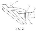
- figure 2 is a schematic partial perspective view of the area where the free end of the dummy twin sting shown in figure 1 is positioned;
- figure 3 is a cross-sectional view along line A-A' appearing in figure 2.
- In these figures, there are reference numbers identifying the following documents:
- 1
- scaled model
- 1a
- empennage of the scaled model
- 1b
- wing of the model
- 1c
- measurement area at the wing of the scaled model
- 2
- main sting
- 3
- dummy twin sting
- 3a
- free end of the dummy twin sting
- 4
- gap
- 5
- sensor means
- Figure 1 shows an embodiment of the system of the present invention in which the
empennage 1a of the scaledmodel 1 is coupled in a per se conventional manner to a main sting 2. Coaxially with the main sting, there is arranged adummy twin sting 3 thefree end 3a of which ends facing ameasurement area 1c at thewing 1b of the scaled model. The system is arranged in a per se conventional wind tunnel through which an air stream is made to flow. - In accordance to what can be seen in figures 2 and 3, in the inside of the
free end 3a of thedummy twin sting 3, there are per se conventional laser-technology based sensor means 5 that project laser beams throughgap 4 on themeasurement area 1c, such that deviations of themeasurement area 1c corresponding to movements of the wing caused by the air stream passing through the tunnel are detected and measured by thesensor elements 5. Themeasurement area 1c emulates the outlet of a turbine positioned atwing 1b. Thefree end 3a of thedummy twin sting 3 is dimensioned and positioned in such a way that it confers aerodynamic continuity with respect to themeasurement area 1c. - The data measured by the sensor means may be processed in a per se conventional manner so as to discriminate the influence of the presence of the
dummy twin sting 3 on the aerodynamic behavior of the scaled model and thus that of a secondary sting used as support for thewing 1b.
Claims (3)
- System for compensating aerodynamic measurements made in a wind tunnel with a testing arrangement comprising a main sting (2) connected to the rear portion of a scaled model emulating at least the empennage (1a) of a wing (1b) of an aircraft, characterized in that the system comprises
a dummy twin sting (3) extending in an axial direction being substantially parallel to the axial position of the main sting (2), with a free end (3a) facing a measurement area (1c) at the rear portion of said wing (1b) in aerodynamic contour configuration;
a gap (4) between said free end (3a) of the dummy twin sting (3) and said measurement area (1c); and
sensor means (5) at said free end (3a) of the dummy twin sting (3) detecting shifting between said measurement area (1c) and said free end (3a) when the scaled model (1) is subjected to an air stream. - System according to claim 1, characterized in that the sensor means (5) comprise an infrared beam transceiver device.
- System according to claim 1, characterized in that the sensor means (S) comprise a laser beam transceiver device.
Applications Claiming Priority (1)
| Application Number | Priority Date | Filing Date | Title |
|---|---|---|---|
| ES200500027A ES2272148B1 (en) | 2004-12-31 | 2004-12-31 | SYSTEM TO COMPENSATE AERODYNAMIC MEASUREMENTS IN A WIND TUNNEL. |
Publications (2)
| Publication Number | Publication Date |
|---|---|
| EP1681546A1 true EP1681546A1 (en) | 2006-07-19 |
| EP1681546B1 EP1681546B1 (en) | 2009-05-27 |
Family
ID=36499136
Family Applications (1)
| Application Number | Title | Priority Date | Filing Date |
|---|---|---|---|
| EP05078060A Expired - Lifetime EP1681546B1 (en) | 2004-12-31 | 2005-12-28 | System for compensating aerodynamic measurements in a wind tunnel |
Country Status (4)
| Country | Link |
|---|---|
| EP (1) | EP1681546B1 (en) |
| AT (1) | ATE432463T1 (en) |
| DE (1) | DE602005014609D1 (en) |
| ES (1) | ES2272148B1 (en) |
Cited By (5)
| Publication number | Priority date | Publication date | Assignee | Title |
|---|---|---|---|---|
| CN103115744A (en) * | 2012-12-27 | 2013-05-22 | 中国航空工业空气动力研究院 | Mirror image supporting rod |
| CN110887635A (en) * | 2019-12-04 | 2020-03-17 | 中国航空工业集团公司哈尔滨空气动力研究所 | A Longitudinal Short Cycle Simulation Test Device for Aircraft Based on Horizontal Wind Tunnel |
| CN113884024A (en) * | 2021-12-06 | 2022-01-04 | 中国空气动力研究与发展中心高速空气动力研究所 | Manufacturing, mounting and detecting method for large wind tunnel contraction section |
| CN113933014A (en) * | 2021-11-29 | 2022-01-14 | 中国航空工业集团公司沈阳空气动力研究所 | A three-freedom vacation support mechanism |
| CN116183154A (en) * | 2023-04-24 | 2023-05-30 | 中国空气动力研究与发展中心高速空气动力研究所 | Ultra-large attack angle wind tunnel test method for slender body model |
Families Citing this family (1)
| Publication number | Priority date | Publication date | Assignee | Title |
|---|---|---|---|---|
| CN107631852B (en) * | 2017-09-01 | 2019-04-12 | 中国航空工业集团公司沈阳空气动力研究所 | Double-support mechanism under a kind of wing |
Citations (2)
| Publication number | Priority date | Publication date | Assignee | Title |
|---|---|---|---|---|
| DE729695C (en) * | 1938-07-19 | 1943-01-09 | Max Hubmeier Dipl Ing | Arrangement for determining the forces occurring in model tests in wind channels |
| US20040253107A1 (en) * | 2002-11-13 | 2004-12-16 | Mark Page | Positioning system for wind tunnel and method of use |
Family Cites Families (3)
| Publication number | Priority date | Publication date | Assignee | Title |
|---|---|---|---|---|
| CA1306879C (en) * | 1988-10-14 | 1992-09-01 | Bertrand Girard | Electrical flechette spin rig for wind tunnel testing |
| JPH05322692A (en) * | 1992-05-26 | 1993-12-07 | Mitsubishi Heavy Ind Ltd | Wind tunnel test device |
| JP3298343B2 (en) * | 1994-12-28 | 2002-07-02 | 株式会社島津製作所 | Calibration device for wind tunnel balance |
-
2004
- 2004-12-31 ES ES200500027A patent/ES2272148B1/en not_active Expired - Fee Related
-
2005
- 2005-12-28 DE DE602005014609T patent/DE602005014609D1/en not_active Expired - Lifetime
- 2005-12-28 EP EP05078060A patent/EP1681546B1/en not_active Expired - Lifetime
- 2005-12-28 AT AT05078060T patent/ATE432463T1/en not_active IP Right Cessation
Patent Citations (2)
| Publication number | Priority date | Publication date | Assignee | Title |
|---|---|---|---|---|
| DE729695C (en) * | 1938-07-19 | 1943-01-09 | Max Hubmeier Dipl Ing | Arrangement for determining the forces occurring in model tests in wind channels |
| US20040253107A1 (en) * | 2002-11-13 | 2004-12-16 | Mark Page | Positioning system for wind tunnel and method of use |
Cited By (8)
| Publication number | Priority date | Publication date | Assignee | Title |
|---|---|---|---|---|
| CN103115744A (en) * | 2012-12-27 | 2013-05-22 | 中国航空工业空气动力研究院 | Mirror image supporting rod |
| CN110887635A (en) * | 2019-12-04 | 2020-03-17 | 中国航空工业集团公司哈尔滨空气动力研究所 | A Longitudinal Short Cycle Simulation Test Device for Aircraft Based on Horizontal Wind Tunnel |
| CN110887635B (en) * | 2019-12-04 | 2022-03-15 | 中国航空工业集团公司哈尔滨空气动力研究所 | Aircraft longitudinal short-period simulation test device based on horizontal wind tunnel |
| CN113933014A (en) * | 2021-11-29 | 2022-01-14 | 中国航空工业集团公司沈阳空气动力研究所 | A three-freedom vacation support mechanism |
| CN113884024A (en) * | 2021-12-06 | 2022-01-04 | 中国空气动力研究与发展中心高速空气动力研究所 | Manufacturing, mounting and detecting method for large wind tunnel contraction section |
| CN113884024B (en) * | 2021-12-06 | 2022-02-08 | 中国空气动力研究与发展中心高速空气动力研究所 | Manufacturing, mounting and detecting method for large wind tunnel contraction section |
| CN116183154A (en) * | 2023-04-24 | 2023-05-30 | 中国空气动力研究与发展中心高速空气动力研究所 | Ultra-large attack angle wind tunnel test method for slender body model |
| CN116183154B (en) * | 2023-04-24 | 2023-06-27 | 中国空气动力研究与发展中心高速空气动力研究所 | Ultra-large attack angle wind tunnel test method for slender body model |
Also Published As
| Publication number | Publication date |
|---|---|
| DE602005014609D1 (en) | 2009-07-09 |
| EP1681546B1 (en) | 2009-05-27 |
| ES2272148B1 (en) | 2008-04-16 |
| ATE432463T1 (en) | 2009-06-15 |
| ES2272148A1 (en) | 2007-04-16 |
Similar Documents
| Publication | Publication Date | Title |
|---|---|---|
| US7819001B2 (en) | Minimum aerodynamic interference support for models in a cryogenic wind tunnel | |
| US6609421B2 (en) | Sideslip correction for a multi-function three probe air data system | |
| EP0229534A2 (en) | Combination pressure probe | |
| US20180335364A1 (en) | Wind tunnel balance and method of use | |
| CN112197932B (en) | Surface temperature correction method and measurement method for airplane anti-icing and deicing test model | |
| EP1681546B1 (en) | System for compensating aerodynamic measurements in a wind tunnel | |
| US20030010109A1 (en) | Method of reducing total temperature errors and multi-function probe implementing same | |
| US8413501B2 (en) | Wake measurement probe | |
| US20150012155A1 (en) | Aircraft comprising a measuring probe and method for determining flight parameters of such an aircraft | |
| US7617023B2 (en) | Process and device for monitoring the validity of a speed cue of an aircraft and system for generating a speed cue comprising such a device | |
| CN108303233A (en) | A high-speed aircraft wind tunnel test device and method for device are twisted in a kind of band pressure turn | |
| Mears et al. | The air flow about an exposed racing wheel | |
| CN112649622A (en) | Pressure sensing probe and fixed-wing aircraft atmospheric data system | |
| CN205209733U (en) | A torque measuring balance | |
| EP0335045A1 (en) | Flow measurement device utilizing force transducers | |
| RU2287795C1 (en) | Device for measurement of aerodynamic force vector's components and of moment | |
| Brune et al. | Induced drag of a simple wing from wake measurements | |
| CN115127771B (en) | Transverse asymmetric weak disturbance wave detection and disturbance source positioning method for high-speed wind tunnel | |
| CN215114462U (en) | Air suspension guide arm detection device | |
| CN110500203B (en) | High-speed free jet angle of attack measurement system of solid rocket ramjet based on weather vane | |
| CN205209734U (en) | Balance installation base | |
| Tokugawa et al. | Transition measurement system of experimental supersonic transport—NEXST-1 | |
| RU2082137C1 (en) | Method of aerodynamic tests of object model | |
| Crowder | Wake imaging system applications at the Boeing Aerodynamics Laboratory | |
| EP2527845A1 (en) | Aircraft wing and sensor |
Legal Events
| Date | Code | Title | Description |
|---|---|---|---|
| PUAI | Public reference made under article 153(3) epc to a published international application that has entered the european phase |
Free format text: ORIGINAL CODE: 0009012 |
|
| AK | Designated contracting states |
Kind code of ref document: A1 Designated state(s): AT BE BG CH CY CZ DE DK EE ES FI FR GB GR HU IE IS IT LI LT LU LV MC NL PL PT RO SE SI SK TR |
|
| AX | Request for extension of the european patent |
Extension state: AL BA HR MK YU |
|
| 17P | Request for examination filed |
Effective date: 20070104 |
|
| AKX | Designation fees paid |
Designated state(s): AT BE BG CH CY CZ DE DK EE ES FI FR GB GR HU IE IS IT LI LT LU LV MC NL PL PT RO SE SI SK TR |
|
| GRAP | Despatch of communication of intention to grant a patent |
Free format text: ORIGINAL CODE: EPIDOSNIGR1 |
|
| GRAS | Grant fee paid |
Free format text: ORIGINAL CODE: EPIDOSNIGR3 |
|
| GRAA | (expected) grant |
Free format text: ORIGINAL CODE: 0009210 |
|
| AK | Designated contracting states |
Kind code of ref document: B1 Designated state(s): AT BE BG CH CY CZ DE DK EE ES FI FR GB GR HU IE IS IT LI LT LU LV MC NL PL PT RO SE SI SK TR |
|
| REG | Reference to a national code |
Ref country code: GB Ref legal event code: FG4D |
|
| REG | Reference to a national code |
Ref country code: CH Ref legal event code: EP |
|
| REG | Reference to a national code |
Ref country code: IE Ref legal event code: FG4D |
|
| REF | Corresponds to: |
Ref document number: 602005014609 Country of ref document: DE Date of ref document: 20090709 Kind code of ref document: P |
|
| PG25 | Lapsed in a contracting state [announced via postgrant information from national office to epo] |
Ref country code: FI Free format text: LAPSE BECAUSE OF FAILURE TO SUBMIT A TRANSLATION OF THE DESCRIPTION OR TO PAY THE FEE WITHIN THE PRESCRIBED TIME-LIMIT Effective date: 20090527 Ref country code: PT Free format text: LAPSE BECAUSE OF FAILURE TO SUBMIT A TRANSLATION OF THE DESCRIPTION OR TO PAY THE FEE WITHIN THE PRESCRIBED TIME-LIMIT Effective date: 20090927 Ref country code: AT Free format text: LAPSE BECAUSE OF FAILURE TO SUBMIT A TRANSLATION OF THE DESCRIPTION OR TO PAY THE FEE WITHIN THE PRESCRIBED TIME-LIMIT Effective date: 20090527 Ref country code: LT Free format text: LAPSE BECAUSE OF FAILURE TO SUBMIT A TRANSLATION OF THE DESCRIPTION OR TO PAY THE FEE WITHIN THE PRESCRIBED TIME-LIMIT Effective date: 20090527 |
|
| NLV1 | Nl: lapsed or annulled due to failure to fulfill the requirements of art. 29p and 29m of the patents act | ||
| PG25 | Lapsed in a contracting state [announced via postgrant information from national office to epo] |
Ref country code: LV Free format text: LAPSE BECAUSE OF FAILURE TO SUBMIT A TRANSLATION OF THE DESCRIPTION OR TO PAY THE FEE WITHIN THE PRESCRIBED TIME-LIMIT Effective date: 20090527 Ref country code: IS Free format text: LAPSE BECAUSE OF FAILURE TO SUBMIT A TRANSLATION OF THE DESCRIPTION OR TO PAY THE FEE WITHIN THE PRESCRIBED TIME-LIMIT Effective date: 20090927 Ref country code: SI Free format text: LAPSE BECAUSE OF FAILURE TO SUBMIT A TRANSLATION OF THE DESCRIPTION OR TO PAY THE FEE WITHIN THE PRESCRIBED TIME-LIMIT Effective date: 20090527 Ref country code: NL Free format text: LAPSE BECAUSE OF FAILURE TO SUBMIT A TRANSLATION OF THE DESCRIPTION OR TO PAY THE FEE WITHIN THE PRESCRIBED TIME-LIMIT Effective date: 20090527 Ref country code: PL Free format text: LAPSE BECAUSE OF FAILURE TO SUBMIT A TRANSLATION OF THE DESCRIPTION OR TO PAY THE FEE WITHIN THE PRESCRIBED TIME-LIMIT Effective date: 20090527 Ref country code: SE Free format text: LAPSE BECAUSE OF FAILURE TO SUBMIT A TRANSLATION OF THE DESCRIPTION OR TO PAY THE FEE WITHIN THE PRESCRIBED TIME-LIMIT Effective date: 20090827 |
|
| PG25 | Lapsed in a contracting state [announced via postgrant information from national office to epo] |
Ref country code: RO Free format text: LAPSE BECAUSE OF FAILURE TO SUBMIT A TRANSLATION OF THE DESCRIPTION OR TO PAY THE FEE WITHIN THE PRESCRIBED TIME-LIMIT Effective date: 20090527 Ref country code: ES Free format text: LAPSE BECAUSE OF FAILURE TO SUBMIT A TRANSLATION OF THE DESCRIPTION OR TO PAY THE FEE WITHIN THE PRESCRIBED TIME-LIMIT Effective date: 20090907 Ref country code: DK Free format text: LAPSE BECAUSE OF FAILURE TO SUBMIT A TRANSLATION OF THE DESCRIPTION OR TO PAY THE FEE WITHIN THE PRESCRIBED TIME-LIMIT Effective date: 20090527 Ref country code: CZ Free format text: LAPSE BECAUSE OF FAILURE TO SUBMIT A TRANSLATION OF THE DESCRIPTION OR TO PAY THE FEE WITHIN THE PRESCRIBED TIME-LIMIT Effective date: 20090527 Ref country code: EE Free format text: LAPSE BECAUSE OF FAILURE TO SUBMIT A TRANSLATION OF THE DESCRIPTION OR TO PAY THE FEE WITHIN THE PRESCRIBED TIME-LIMIT Effective date: 20090527 |
|
| RAP2 | Party data changed (patent owner data changed or rights of a patent transferred) |
Owner name: AIRBUS OPERATIONS S.L. |
|
| PG25 | Lapsed in a contracting state [announced via postgrant information from national office to epo] |
Ref country code: BE Free format text: LAPSE BECAUSE OF FAILURE TO SUBMIT A TRANSLATION OF THE DESCRIPTION OR TO PAY THE FEE WITHIN THE PRESCRIBED TIME-LIMIT Effective date: 20090527 Ref country code: SK Free format text: LAPSE BECAUSE OF FAILURE TO SUBMIT A TRANSLATION OF THE DESCRIPTION OR TO PAY THE FEE WITHIN THE PRESCRIBED TIME-LIMIT Effective date: 20090527 |
|
| PG25 | Lapsed in a contracting state [announced via postgrant information from national office to epo] |
Ref country code: BG Free format text: LAPSE BECAUSE OF FAILURE TO SUBMIT A TRANSLATION OF THE DESCRIPTION OR TO PAY THE FEE WITHIN THE PRESCRIBED TIME-LIMIT Effective date: 20090827 |
|
| PLBE | No opposition filed within time limit |
Free format text: ORIGINAL CODE: 0009261 |
|
| REG | Reference to a national code |
Ref country code: FR Ref legal event code: CD |
|
| STAA | Information on the status of an ep patent application or granted ep patent |
Free format text: STATUS: NO OPPOSITION FILED WITHIN TIME LIMIT |
|
| 26N | No opposition filed |
Effective date: 20100302 |
|
| PG25 | Lapsed in a contracting state [announced via postgrant information from national office to epo] |
Ref country code: MC Free format text: LAPSE BECAUSE OF NON-PAYMENT OF DUE FEES Effective date: 20100701 |
|
| REG | Reference to a national code |
Ref country code: CH Ref legal event code: PL |
|
| REG | Reference to a national code |
Ref country code: IE Ref legal event code: MM4A |
|
| PG25 | Lapsed in a contracting state [announced via postgrant information from national office to epo] |
Ref country code: CH Free format text: LAPSE BECAUSE OF NON-PAYMENT OF DUE FEES Effective date: 20091231 Ref country code: IE Free format text: LAPSE BECAUSE OF NON-PAYMENT OF DUE FEES Effective date: 20091228 Ref country code: LI Free format text: LAPSE BECAUSE OF NON-PAYMENT OF DUE FEES Effective date: 20091231 Ref country code: GR Free format text: LAPSE BECAUSE OF FAILURE TO SUBMIT A TRANSLATION OF THE DESCRIPTION OR TO PAY THE FEE WITHIN THE PRESCRIBED TIME-LIMIT Effective date: 20090828 |
|
| PG25 | Lapsed in a contracting state [announced via postgrant information from national office to epo] |
Ref country code: LU Free format text: LAPSE BECAUSE OF NON-PAYMENT OF DUE FEES Effective date: 20091228 |
|
| PG25 | Lapsed in a contracting state [announced via postgrant information from national office to epo] |
Ref country code: HU Free format text: LAPSE BECAUSE OF FAILURE TO SUBMIT A TRANSLATION OF THE DESCRIPTION OR TO PAY THE FEE WITHIN THE PRESCRIBED TIME-LIMIT Effective date: 20091128 |
|
| PG25 | Lapsed in a contracting state [announced via postgrant information from national office to epo] |
Ref country code: TR Free format text: LAPSE BECAUSE OF FAILURE TO SUBMIT A TRANSLATION OF THE DESCRIPTION OR TO PAY THE FEE WITHIN THE PRESCRIBED TIME-LIMIT Effective date: 20090527 |
|
| PG25 | Lapsed in a contracting state [announced via postgrant information from national office to epo] |
Ref country code: CY Free format text: LAPSE BECAUSE OF FAILURE TO SUBMIT A TRANSLATION OF THE DESCRIPTION OR TO PAY THE FEE WITHIN THE PRESCRIBED TIME-LIMIT Effective date: 20090527 |
|
| REG | Reference to a national code |
Ref country code: FR Ref legal event code: PLFP Year of fee payment: 11 |
|
| PGFP | Annual fee paid to national office [announced via postgrant information from national office to epo] |
Ref country code: DE Payment date: 20151211 Year of fee payment: 11 Ref country code: GB Payment date: 20151221 Year of fee payment: 11 |
|
| PGFP | Annual fee paid to national office [announced via postgrant information from national office to epo] |
Ref country code: FR Payment date: 20151221 Year of fee payment: 11 |
|
| PGFP | Annual fee paid to national office [announced via postgrant information from national office to epo] |
Ref country code: IT Payment date: 20151228 Year of fee payment: 11 |
|
| REG | Reference to a national code |
Ref country code: DE Ref legal event code: R119 Ref document number: 602005014609 Country of ref document: DE |
|
| GBPC | Gb: european patent ceased through non-payment of renewal fee |
Effective date: 20161228 |
|
| REG | Reference to a national code |
Ref country code: FR Ref legal event code: ST Effective date: 20170831 |
|
| PG25 | Lapsed in a contracting state [announced via postgrant information from national office to epo] |
Ref country code: IT Free format text: LAPSE BECAUSE OF NON-PAYMENT OF DUE FEES Effective date: 20161228 Ref country code: FR Free format text: LAPSE BECAUSE OF NON-PAYMENT OF DUE FEES Effective date: 20170102 |
|
| PG25 | Lapsed in a contracting state [announced via postgrant information from national office to epo] |
Ref country code: GB Free format text: LAPSE BECAUSE OF NON-PAYMENT OF DUE FEES Effective date: 20161228 Ref country code: DE Free format text: LAPSE BECAUSE OF NON-PAYMENT OF DUE FEES Effective date: 20170701 |