EP1681473B1 - Compressor wheel - Google Patents
Compressor wheel Download PDFInfo
- Publication number
- EP1681473B1 EP1681473B1 EP05027421A EP05027421A EP1681473B1 EP 1681473 B1 EP1681473 B1 EP 1681473B1 EP 05027421 A EP05027421 A EP 05027421A EP 05027421 A EP05027421 A EP 05027421A EP 1681473 B1 EP1681473 B1 EP 1681473B1
- Authority
- EP
- European Patent Office
- Prior art keywords
- compressor wheel
- extension
- joint
- compressor
- shaft
- Prior art date
- Legal status (The legal status is an assumption and is not a legal conclusion. Google has not performed a legal analysis and makes no representation as to the accuracy of the status listed.)
- Expired - Lifetime
Links
Images




Classifications
-
- F—MECHANICAL ENGINEERING; LIGHTING; HEATING; WEAPONS; BLASTING
- F01—MACHINES OR ENGINES IN GENERAL; ENGINE PLANTS IN GENERAL; STEAM ENGINES
- F01D—NON-POSITIVE DISPLACEMENT MACHINES OR ENGINES, e.g. STEAM TURBINES
- F01D5/00—Blades; Blade-carrying members; Heating, heat-insulating, cooling or antivibration means on the blades or the members
- F01D5/02—Blade-carrying members, e.g. rotors
- F01D5/025—Fixing blade carrying members on shafts
-
- F—MECHANICAL ENGINEERING; LIGHTING; HEATING; WEAPONS; BLASTING
- F04—POSITIVE - DISPLACEMENT MACHINES FOR LIQUIDS; PUMPS FOR LIQUIDS OR ELASTIC FLUIDS
- F04D—NON-POSITIVE-DISPLACEMENT PUMPS
- F04D29/00—Details, component parts, or accessories
- F04D29/26—Rotors specially for elastic fluids
- F04D29/266—Rotors specially for elastic fluids mounting compressor rotors on shafts
-
- F—MECHANICAL ENGINEERING; LIGHTING; HEATING; WEAPONS; BLASTING
- F04—POSITIVE - DISPLACEMENT MACHINES FOR LIQUIDS; PUMPS FOR LIQUIDS OR ELASTIC FLUIDS
- F04D—NON-POSITIVE-DISPLACEMENT PUMPS
- F04D29/00—Details, component parts, or accessories
- F04D29/66—Combating cavitation, whirls, noise, vibration or the like; Balancing
- F04D29/661—Combating cavitation, whirls, noise, vibration or the like; Balancing especially adapted for elastic fluid pumps
- F04D29/662—Balancing of rotors
-
- F—MECHANICAL ENGINEERING; LIGHTING; HEATING; WEAPONS; BLASTING
- F05—INDEXING SCHEMES RELATING TO ENGINES OR PUMPS IN VARIOUS SUBCLASSES OF CLASSES F01-F04
- F05D—INDEXING SCHEME FOR ASPECTS RELATING TO NON-POSITIVE-DISPLACEMENT MACHINES OR ENGINES, GAS-TURBINES OR JET-PROPULSION PLANTS
- F05D2220/00—Application
- F05D2220/40—Application in turbochargers
Definitions
- Subject matter disclosed herein relates generally to methods, devices, and/or systems for compressors and, in particular, compressors for internal combustion engines.
- a boreless compressor wheel includes a joint or chamber that extends a distance into the compressor wheel where the distance along the rotational axis typically does not extend to or beyond the z-plane of the compressor wheel.
- the bore or joint must be formed or machined into the compressor wheel. Stresses introduced by such processes may compromise wheel integrity such that a wheel fails during operation. Yet further, if one chooses to use titanium or other hard material for a compressor wheel, machining of a joint can be time and resource intensive.
- Compressor wheels may be component balanced using a balancing spindle and/or assembly balanced using a compressor or turbocharger shaft.
- Each approach has certain advantages, for example, component balancing allows for rejection of a compressor wheel prior to further compressor or turbocharger assembly; whereas, assembly balancing can result in a better performing compressor wheel and shaft assembly.
- Turbochargers are frequently utilized to increase the output of an internal combustion engine.
- a system 100 including an exemplary internal combustion engine 110 and an exemplary turbocharger 120, is shown.
- the internal combustion engine 110 includes an engine block 118 housing one or more combustion chambers that operatively drive a shaft 112.
- an intake port 114 provides a flow path for air to the engine block while an exhaust port 116 provides a flow path for exhaust from the engine block 118.
- the exemplary turbocharger 120 acts to extract energy from the exhaust and to provide energy to intake air, which may be combined with fuel to form combustion gas.
- the turbocharger 120 includes an air inlet 134, a shaft 122, a compressor 124, a turbine 126, and an exhaust outlet 136.
- a wastegate or other mechanism may be used in conjunction with such a system to effect or to control operation.
- the turbine 126 optionally includes a variable geometry unit and a variable geometry controller.
- the variable geometry unit and variable geometry controller optionally include features such as those associated with commercially available variable geometry turbochargers (VGTs), such as, but not limited to, the GARRETT® VNTTM and AVNTTM turbochargers, which use multiple adjustable vanes to control the flow of exhaust across a turbine.
- VVTs variable geometry turbochargers
- GARRETT® VNTTM and AVNTTM turbochargers which use multiple adjustable vanes to control the flow of exhaust across a turbine.
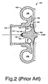
- Fig. 2 shows a cross-sectional view of a typical prior art compressor assembly 124 suitable for use in the turbocharger system 120 of Fig. 1 .
- the compressor assembly 124 includes a housing 150 for shrouding a compressor wheel 140.
- the compressor wheel 140 includes a rotor 142 that rotates about a central axis (e.g., a rotational axis).
- a bore 160 extends the entire length of the central axis of the rotor 142 (e.g., an axial rotor length); therefore, such a rotor is referred to at times as a full-bore rotor.
- An end piece 162 fits onto an upstream end of the rotor 142 and may act to secure a shaft and/or to reduce disturbances in air flow.
- a shaft has a compressor end and a turbine end wherein the turbine end attaches to a turbine capable of being driven by an exhaust stream.
- the compressor wheel blade 144 has a leading edge portion 144 proximate to a compressor inlet opening 152, an outer edge portion 146 proximate to a shroud wall 154 and a trailing edge portion 148 proximate to a compressor housing diffuser 156.
- the shroud wall 154 proximate to the compressor wheel blade 144, defines a section sometimes referred to herein as a shroud of compressor volute housing 150.
- the compressor housing shroud wall after the wheel outlet 156 forms part of a compressor diffuser that further diffuses the flow and increases the static pressure.
- a housing scroll 158, 159 acts to collect and direct compressed air.
- Fig. 2 does not intend to show all possible variations in scroll cross-sections, but rather, it intends to show how a compressor wheel may be positioned with respect to a compressor wheel housing.
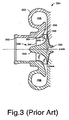
- Fig. 3 shows a cross-sectional view of a conventional prior art compressor wheel rotor 324 that includes a "boreless" compressor wheel 340 suitable for use in the turbocharger system 120 of Fig. 1 .
- the compressor assembly 324 includes a housing 350 for shrouding a compressor wheel 340.
- the compressor wheel 340 includes a rotor 342 that rotates about a central axis. Attached to the rotor 342, are a plurality of compressor wheel blades 344, which extend radially from a surface of the rotor.
- the compressor wheel blade 344 has a leading edge portion 344 proximate to a compressor inlet opening 352, an outer edge portion 346 proximate to a shroud wall 354 and a trailing edge portion 348 proximate to a compressor housing diffuser 356.
- the shroud wall 354, proximate to the compressor wheel blade 344 defines a section sometimes referred to herein as a shroud of compressor volute housing 350.
- the compressor housing shroud wall after the wheel outlet 356 forms part of a compressor diffuser that further diffuses the flow and increases the static pressure.
- a housing scroll 358, 359 acts to collect and direct compressed air.
- Fig. 3 shows a z-plane as coinciding substantially with a lowermost point of an outer edge or trailing edge portion 348 of the blade 344.
- a bore or joint 360 centered substantially on a rotor axis exists at a proximate end of the rotor 342 for receiving a shaft.
- the bore or joint 360 is, for example, a place at which two or more things are joined (e.g., a compressor wheel and a shaft or a spindle, etc.).
- Compressor wheels having a joint such as the joint 360 are sometimes referred to as "boreless" compressor wheels in that the joint does not pass or extend through the entire length of the compressor wheel: Indeed, such conventional boreless compressor wheels do not have joints that extend to the depth of the z-plane.
- the joint 360 typically receives a shaft that has a compressor end and a turbine end wherein the turbine end attaches to a turbine capable of being driven by an exhaust stream.
- the joint 360 may receive a balancing spindle; however, such a balancing spindle cannot extend to or beyond the z-plane because of the joint depth.
- an important parameter in machining such a joint pertains to the distance between the z-plane and the end of the joint.
- Fig. 4 shows a cross-sectional view of a prior art compressor wheel assembly that includes a compressor wheel 340, a thrust collar 370, a ring 372 and a shaft 380.
- the compressor wheel 340 includes a joint 360 ⁇ z b indicates a distance between the end of the joint 360 and the z-plane.
- a maximum in stress occurs at or near the end of the joint 360 and along the z-axis. Integrity of the wheel 360 typically decreases as the distance ⁇ z b diminishes; thus, the position of the end surface of the joint 360 must be carefully manufactured with respect to the z-plane of the wheel 340 and with respect to surface imperfections.
- Fig. 4 shows another distance ⁇ z c , which represents an overhang distance as measured from the z-plane to the end surface of the wheel 340 where, for example, the wheel meets the thrust collar 370.
- the overhang distance or length can affect stability and, in general, a short overhang results in greater stability (e.g., bearing stability, rotordynamic stability, etc.).
- the conventional boreless wheel 340 also includes a radial distance ⁇ r, along the joint length that may vary with respect to axial position. Such a distance may be used to calculate an overhang volume and, hence, an overhang mass. Overhang properties such as mass and extended distance from the z-plane may be used to determine stability.
- a typical compressor wheel and shaft assembly includes a thrust collar that forms a portion of a thrust bearing assembly.
- Such an assembly may include a thrust spacer sleeve, a ring and/or other components.
- a thrust space sleeve is typically threaded onto a shaft to axially bearing engagement with a shoulder, such as a thrust collar or the like, forming a portion of the thrust bearing assembly and being rotatable with the shaft. In this manner, the sleeve spaces the compressor wheel axially relative to the thrust collar.
- the sleeve advantageously receives seal rings in its outer diameter grooves where the seal rings engage the inner diameter surface of the backplate wall shaft opening to prevent lubricant passage from the center housing into the compressor housing. As shown in Fig.
- a ring 372 is positioned between the thrust collar 370 and the compressor wheel 340. While a ring is shown in Fig. 4 , a carbon seal, labyrinth seal or other mechanism may be used.
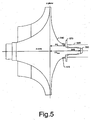
- Fig. 5 shows a cross-sectional view of an exemplary compressor wheel assembly that includes a compressor wheel 540, a thrust collar 570, a ring 572 and a shaft 580.
- the exemplary compressor wheel 540 includes an extension 549 for insertion in a joint 590 of the exemplary shaft 580.
- the extension 549 extends a distance ⁇ z max along the z-axis from the z-plane.
- the exemplary wheel 540 includes a thrust collar distance ⁇ z c from the z-plane to a surface that, for example, meets the thrust collar 570.
- the ring 572 may be positioned between a surface of the compressor wheel 540 and a surface of the thrust collar 570.
- the exemplary compressor wheel 540 includes a substantially annular surface at a distance of ⁇ z c from the z-plane and in a plane substantially normal to the axis of rotation. This surface may act to seat the thrust collar 570.
- a notch or other surface may confine the ring 572 between the thrust collar 570 and the wheel 540.
- Various exemplary wheels include a distance from the z-plane (e.g., ⁇ z c ) to a a surface or position from which an extension extends. This distance may be less than the distance from the z-plane to the end of a conventional boreless or bored compressor wheel that does not have such an extension.
- the ratio of ⁇ z c to ⁇ z max can vary, as appropriate, for example, to achieve a shift in the center of gravity away from the nose of the wheel (e.g., in comparison to a wheel having a bore or conventional boreless design), etc.
- a compressor wheel extension reduces the distance from the z-plane to an operational shaft of a turbocharger when compared to a conventional compressor wheel.
- Fig. 6 shows a cross-sectional view of an exemplary joint that includes a compressor wheel 540 and a shaft 580 such as those shown in Fig. 5 .
- Fig. 6 shows various dimensions including a distance ⁇ z r from the z-plane to a point where the exemplary wheel 540 reaches a substantially constant outer radius with respect to the z-axis; a distance Az S from the z-plane to the outermost axial point of the exemplary shaft 580; a diameter d Pi , which represents an inner pilot diameter of the extension 549; a distance ⁇ z c , which represents the axial length of the extension 549; a diameter dp o , which represents an outer pilot diameter of the extension 549; and a diameter d S , which represents a shaft diameter.
- the exemplary shaft 580 includes a joint 590 to receive the extension 549.
- the example of Fig. 6 shows the joint 590 as including an optional contoured end surface.
- the shaft 580 has a substantially constant outer diameter proximate the compressor wheel 540. A constant outer diameter acts to minimize stress of the shaft 580. Consequently, the presence of the joint 590 in the shaft 580 does not necessitate stress reduction measured or concerns such as those associated with a conventional boreless wheel where outer radius varies significantly along the z-axis.
- Various exemplary compressor wheels allow for a reduced overhang length compared to conventional boreless compressor wheels.
- a reduction in overhang length may also allow for a reduction in overall length of a compressor section of, for example, a turbocharger and thereby yielding a stable rotor and turbocharger system.
- the exemplary compressor wheel 540 includes a first pilot diameter d Pi for alignment with the thrust collar 570 and a second pilot diameter d Po for alignment with a pilot surface of the joint 590 of the exemplary shaft 580. Disposed between the pilot surfaces are threads or other engagement mechanism or means (e.g., bayonet, etc.).
- the exemplary shaft 580 includes a corresponding or complimentary threads or engagement mechanism or means (e.g., bayonet, etc.).
- An exemplary joint may be defined by one or more regions, volumes, surfaces and/or dimensions.
- the exemplary joint 590 includes a proximate region (e.g., consider diameter d Pi ), an intermediate region (e.g., consider threads) and a distal region (e.g., consider diameter d Po ).
- Such regions may be referred to as pilot regions and/or co-pilot regions or threaded regions, as appropriate.
- An intermediate region or other region may include threads or other fixing mechanism (e.g., bayonet, etc.). Where threads are included, the threads typically match a set of threads of an exemplary compressor wheel.
- An exemplary joint may include one or more annular constrictions, for example, disposed near a juncture between regions where the one or more annular constrictions decrease in diameter with respect to increasing length along the axis of rotation and may form a surface disposed at an angle with respect to the axis of rotation.
- a constriction may act to minimize or eliminate any damage created by machining (e.g., boring, taping, etc.).
- Materials of construction for an exemplary compressor wheel are not limited to aluminum and titanium and may include stainless steel, etc.
- Materials of construction optionally include alloys.
- Ti-6A1-4V (wt.-%), also known as Ti6-4, is alloy that includes titanium as well as aluminum and vanadium.
- Such alloy may have a duplex structure, where a main component is a hexagonal ⁇ -phase and a minor component is a cubic ⁇ -phase stabilized by vanadium.
- Implantation of other elements may enhance hardness (e.g., nitrogen implantation, etc.) as appropriate.
- An exemplary compressor wheel may include, for component balancing, a balancing unit that cooperates with one or more features of the compressor wheel (e.g., extension features).
- a balancing unit may include a joint such as the joint S90 of the exemplary shaft 580.
- Fig. 7 shows a block diagram of an exemplary method 700.
- the method 700 commences in a start block 704, which includes providing a compressor wheel and a balancing machine having a balancing unit.
- the balancing unit receives an exemplary extension.
- an operator may insert the extension, at least partially, into a joint of a balancing unit.
- Such a joint may include one or more pilot surfaces that receive one or more pilot surfaces of the extension.
- a balance block 712 follows wherein a balancing process occurs.
- balancing is dynamic balancing.
- the compressor wheel extension is removed from the joint of the balancing unit.
- an exemplary shaft receives the extension wherein other components are positioned or assembled as appropriate.
- the method 700 may terminate in an end block 724.
- the method 700 optionally includes another balancing block wherein the compressor wheel and operational shaft are balanced as an assembly.
- the exemplary shaft is used in a balancing process for an exemplary compressor wheel.
- the exemplary method 700 and/or portions thereof are optionally performed using hardware and/or software.
- the method and/or portions thereof may be performed using robotics and/or other computer controllable machinery.
- exemplary compressor wheels disclosed herein include a proximate end, a distal end, an axis of rotation, a z-plane positioned between the proximate end and the distal end, and an extension having an axis coincident with the axis of rotation.
- An exemplary shaft includes a complimentary joint to receive the extension, at least partially therein.
- An exemplary shaft joint may include a contoured end surface optionally having an elliptical cross-section (e.g., radius to height ratio of approximately 3:1, etc.).
- An exemplary compressor wheel optionally includes titanium, titanium alloy (e.g., Ti6-4, etc.) or other material having same or similar mechanical properties. Such a compressor wheel optionally has a peak principle operational stress less than that of a conventional boreless compressor wheel.
- Various exemplary compressor wheels are optionally part of an assembly (e.g., a balancing assembly, a turbocharger assembly, a compressor assembly, etc.).
- An exemplary assembly includes an exemplary compressor wheel and an exemplary operational shaft.
Landscapes
- Engineering & Computer Science (AREA)
- Mechanical Engineering (AREA)
- General Engineering & Computer Science (AREA)
- Structures Of Non-Positive Displacement Pumps (AREA)
- Supercharger (AREA)
Description
- Subject matter disclosed herein relates generally to methods, devices, and/or systems for compressors and, in particular, compressors for internal combustion engines.
- Various types of joints exist for connecting a compressor wheel to a shaft.
Document EP 1 270 951 A1 discloses e.g. a compressor wheel assembly comprising all the features of the preamble ofclaim 1. Some joints rely on a bore in the compressor wheel along the axis of rotation. In such joints, a shaft passes through the bore and a nut secures the wheel to the shaft. Other joints rely on a "boreless" compressor wheel. A boreless compressor wheel includes a joint or chamber that extends a distance into the compressor wheel where the distance along the rotational axis typically does not extend to or beyond the z-plane of the compressor wheel. - In either instance, the bore or joint must be formed or machined into the compressor wheel. Stresses introduced by such processes may compromise wheel integrity such that a wheel fails during operation. Yet further, if one chooses to use titanium or other hard material for a compressor wheel, machining of a joint can be time and resource intensive.
- Another concern pertains to balancing a compressor wheel. Boreless compressor wheels pose unique challenges for balancing. Compressor wheels may be component balanced using a balancing spindle and/or assembly balanced using a compressor or turbocharger shaft. Each approach has certain advantages, for example, component balancing allows for rejection of a compressor wheel prior to further compressor or turbocharger assembly; whereas, assembly balancing can result in a better performing compressor wheel and shaft assembly.
- For conventional boreless compressor wheels, balancing limitations arise due to aspects of the boreless design. In particular, conventional boreless compressor wheels require shallow shaft attachment joints (e.g., typically not extending to or beyond the z-plane) to minimize operational stress. Such shallow joints can introduce severe manufacturing constraints. To overcome such constraints and/or other issues, a need exists for a new compressor wheel joint. Accordingly, various exemplary joints, compressor wheels, balancing spindles, assemblies and methods are presented herein that aim to meet aforementioned needs and/or other needs.
- A more complete understanding of the various method, devices, systems, etc., described herein, and equivalents thereof, may be had by reference to the following detailed description when taken in conjunction with the accompanying drawings wherein:
-
Fig. 1 is a simplified approximate diagram illustrating a turbocharger with a variable geometry mechanism and an internal combustion engine. -
Fig. 2 is a cross-sectional view of a prior art compressor assembly that includes a compressor shroud and a compressor wheel having a full bore. -
Fig. 3 is a cross-sectional view of a prior art compressor assembly that includes a compressor shroud and a conventional "boreless" compressor wheel. -
Fig. 4 is a cross-sectional view of a prior art compressor wheel assembly that includes a shaft and other components. -
Fig. 5 is a cross-sectional view of an exemplary compressor wheel assembly that includes an exemplary shaft and other components. -
Fig. 6 is a cross-sectional view of the exemplary joint ofFig. 5 . -
Fig. 7 is a block diagram of an exemplary method for balancing a compressor wheel. - Various exemplary devices, systems, methods, etc., disclosed herein address issues related to compressors. An overview of turbocharger operation is presented below followed by a description of conventional compressor wheel joints, exemplary compressor wheel joints and an exemplary method of compressor wheel balancing.
- Turbochargers are frequently utilized to increase the output of an internal combustion engine. Referring to
Fig. 1 , anexemplary system 100, including an exemplaryinternal combustion engine 110 and anexemplary turbocharger 120, is shown. Theinternal combustion engine 110 includes anengine block 118 housing one or more combustion chambers that operatively drive ashaft 112. As shown inFig. 1 , anintake port 114 provides a flow path for air to the engine block while anexhaust port 116 provides a flow path for exhaust from theengine block 118. - The
exemplary turbocharger 120 acts to extract energy from the exhaust and to provide energy to intake air, which may be combined with fuel to form combustion gas. As shown inFig. 1 , theturbocharger 120 includes anair inlet 134, ashaft 122, acompressor 124, aturbine 126, and anexhaust outlet 136. A wastegate or other mechanism may be used in conjunction with such a system to effect or to control operation. - The
turbine 126 optionally includes a variable geometry unit and a variable geometry controller. The variable geometry unit and variable geometry controller optionally include features such as those associated with commercially available variable geometry turbochargers (VGTs), such as, but not limited to, the GARRETT® VNT™ and AVNT™ turbochargers, which use multiple adjustable vanes to control the flow of exhaust across a turbine. -
Fig. 2 shows a cross-sectional view of a typical priorart compressor assembly 124 suitable for use in theturbocharger system 120 ofFig. 1 . Thecompressor assembly 124 includes ahousing 150 for shrouding acompressor wheel 140. Thecompressor wheel 140 includes arotor 142 that rotates about a central axis (e.g., a rotational axis). Abore 160 extends the entire length of the central axis of the rotor 142 (e.g., an axial rotor length); therefore, such a rotor is referred to at times as a full-bore rotor. Anend piece 162 fits onto an upstream end of therotor 142 and may act to secure a shaft and/or to reduce disturbances in air flow. In general, such a shaft has a compressor end and a turbine end wherein the turbine end attaches to a turbine capable of being driven by an exhaust stream. - Referring again to the
compressor wheel 140, attached to therotor 142, are a plurality ofcompressor wheel blades 144, which extend radially from a surface of the rotor. As shown, thecompressor wheel blade 144 has a leadingedge portion 144 proximate to acompressor inlet opening 152, anouter edge portion 146 proximate to ashroud wall 154 and atrailing edge portion 148 proximate to acompressor housing diffuser 156. Theshroud wall 154, proximate to thecompressor wheel blade 144, defines a section sometimes referred to herein as a shroud ofcompressor volute housing 150. The compressor housing shroud wall after thewheel outlet 156 forms part of a compressor diffuser that further diffuses the flow and increases the static pressure. A housing scroll 158, 159 acts to collect and direct compressed air. - Some symmetry exists between the upper portion of the
housing scroll 158 and the lower portion of thehousing scroll 159. In general, one portion has a smaller cross-sectional area than the other portion; thus, substantial differences may exist between theupper portion 158 and thelower portion 159.Fig. 2 does not intend to show all possible variations in scroll cross-sections, but rather, it intends to show how a compressor wheel may be positioned with respect to a compressor wheel housing. -
Fig. 3 shows a cross-sectional view of a conventional prior artcompressor wheel rotor 324 that includes a "boreless"compressor wheel 340 suitable for use in theturbocharger system 120 ofFig. 1 . Thecompressor assembly 324 includes ahousing 350 for shrouding acompressor wheel 340. Thecompressor wheel 340 includes arotor 342 that rotates about a central axis. Attached to therotor 342, are a plurality ofcompressor wheel blades 344, which extend radially from a surface of the rotor. As shown, thecompressor wheel blade 344 has a leadingedge portion 344 proximate to a compressor inlet opening 352, an outer edge portion 346 proximate to ashroud wall 354 and atrailing edge portion 348 proximate to acompressor housing diffuser 356. Theshroud wall 354, proximate to thecompressor wheel blade 344, defines a section sometimes referred to herein as a shroud of compressor volutehousing 350. The compressor housing shroud wall after thewheel outlet 356 forms part of a compressor diffuser that further diffuses the flow and increases the static pressure. A housing scroll 358, 359 acts to collect and direct compressed air. -
Fig. 3 shows a z-plane as coinciding substantially with a lowermost point of an outer edge ortrailing edge portion 348 of theblade 344. A bore or joint 360 centered substantially on a rotor axis exists at a proximate end of therotor 342 for receiving a shaft. Throughout this disclosure, the bore or joint 360 is, for example, a place at which two or more things are joined (e.g., a compressor wheel and a shaft or a spindle, etc.). Compressor wheels having a joint such as the joint 360 are sometimes referred to as "boreless" compressor wheels in that the joint does not pass or extend through the entire length of the compressor wheel: Indeed, such conventional boreless compressor wheels do not have joints that extend to the depth of the z-plane. The joint 360 typically receives a shaft that has a compressor end and a turbine end wherein the turbine end attaches to a turbine capable of being driven by an exhaust stream. For purposes of compressor wheel balancing, the joint 360 may receive a balancing spindle; however, such a balancing spindle cannot extend to or beyond the z-plane because of the joint depth. As discussed below with respect toFig. 4 , an important parameter in machining such a joint pertains to the distance between the z-plane and the end of the joint. -
Fig. 4 shows a cross-sectional view of a prior art compressor wheel assembly that includes acompressor wheel 340, athrust collar 370, aring 372 and ashaft 380. Thecompressor wheel 340 includes a joint 360 Δzb indicates a distance between the end of the joint 360 and the z-plane. In the priorart compressor wheel 340, a maximum in stress occurs at or near the end of the joint 360 and along the z-axis. Integrity of thewheel 360 typically decreases as the distance Δzb diminishes; thus, the position of the end surface of the joint 360 must be carefully manufactured with respect to the z-plane of thewheel 340 and with respect to surface imperfections. -
Fig. 4 shows another distance Δzc, which represents an overhang distance as measured from the z-plane to the end surface of thewheel 340 where, for example, the wheel meets thethrust collar 370. The overhang distance or length can affect stability and, in general, a short overhang results in greater stability (e.g., bearing stability, rotordynamic stability, etc.). Theconventional boreless wheel 340 also includes a radial distance Δr, along the joint length that may vary with respect to axial position. Such a distance may be used to calculate an overhang volume and, hence, an overhang mass. Overhang properties such as mass and extended distance from the z-plane may be used to determine stability. - A typical compressor wheel and shaft assembly includes a thrust collar that forms a portion of a thrust bearing assembly. Such an assembly may include a thrust spacer sleeve, a ring and/or other components. A thrust space sleeve is typically threaded onto a shaft to axially bearing engagement with a shoulder, such as a thrust collar or the like, forming a portion of the thrust bearing assembly and being rotatable with the shaft. In this manner, the sleeve spaces the compressor wheel axially relative to the thrust collar. In addition, the sleeve advantageously receives seal rings in its outer diameter grooves where the seal rings engage the inner diameter surface of the backplate wall shaft opening to prevent lubricant passage from the center housing into the compressor housing. As shown in
Fig. 4 , aring 372 is positioned between thethrust collar 370 and thecompressor wheel 340. While a ring is shown inFig. 4 , a carbon seal, labyrinth seal or other mechanism may be used.
Fig. 5 shows a cross-sectional view of an exemplary compressor wheel assembly that includes acompressor wheel 540, athrust collar 570, aring 572 and ashaft 580. Theexemplary compressor wheel 540 includes anextension 549 for insertion in a joint 590 of theexemplary shaft 580. In this example, theextension 549 extends a distance Δzmax along the z-axis from the z-plane. Theexemplary wheel 540 includes a thrust collar distance Δzc from the z-plane to a surface that, for example, meets thethrust collar 570. Thering 572 may be positioned between a surface of thecompressor wheel 540 and a surface of thethrust collar 570. As shown, theexemplary compressor wheel 540 includes a substantially annular surface at a distance of Δzc from the z-plane and in a plane substantially normal to the axis of rotation. This surface may act to seat thethrust collar 570. A notch or other surface may confine thering 572 between thethrust collar 570 and thewheel 540. - Various exemplary wheels include a distance from the z-plane (e.g., Δzc) to a a surface or position from which an extension extends. This distance may be less than the distance from the z-plane to the end of a conventional boreless or bored compressor wheel that does not have such an extension. For various exemplary compressor wheels, the ratio of Δzc to Δzmax can vary, as appropriate, for example, to achieve a shift in the center of gravity away from the nose of the wheel (e.g., in comparison to a wheel having a bore or conventional boreless design), etc. In various examples, a compressor wheel extension reduces the distance from the z-plane to an operational shaft of a turbocharger when compared to a conventional compressor wheel.
-
Fig. 6 shows a cross-sectional view of an exemplary joint that includes acompressor wheel 540 and ashaft 580 such as those shown inFig. 5 .Fig. 6 shows various dimensions including a distance Δzr from the z-plane to a point where theexemplary wheel 540 reaches a substantially constant outer radius with respect to the z-axis; a distance AzS from the z-plane to the outermost axial point of theexemplary shaft 580; a diameter dPi, which represents an inner pilot diameter of theextension 549; a distance Δzc, which represents the axial length of theextension 549; a diameter dpo, which represents an outer pilot diameter of theextension 549; and a diameter dS, which represents a shaft diameter. - The
exemplary shaft 580 includes a joint 590 to receive theextension 549. The example ofFig. 6 shows the joint 590 as including an optional contoured end surface. In general, theshaft 580 has a substantially constant outer diameter proximate thecompressor wheel 540. A constant outer diameter acts to minimize stress of theshaft 580. Consequently, the presence of the joint 590 in theshaft 580 does not necessitate stress reduction measured or concerns such as those associated with a conventional boreless wheel where outer radius varies significantly along the z-axis. - Various exemplary compressor wheels allow for a reduced overhang length compared to conventional boreless compressor wheels. A reduction in overhang length may also allow for a reduction in overall length of a compressor section of, for example, a turbocharger and thereby yielding a stable rotor and turbocharger system.
- In the example of
Fig. 6 , theexemplary compressor wheel 540 includes a first pilot diameter dPi for alignment with thethrust collar 570 and a second pilot diameter dPo for alignment with a pilot surface of the joint 590 of theexemplary shaft 580. Disposed between the pilot surfaces are threads or other engagement mechanism or means (e.g., bayonet, etc.). Theexemplary shaft 580 includes a corresponding or complimentary threads or engagement mechanism or means (e.g., bayonet, etc.). - An exemplary joint may be defined by one or more regions, volumes, surfaces and/or dimensions. For example, the exemplary joint 590 includes a proximate region (e.g., consider diameter dPi), an intermediate region (e.g., consider threads) and a distal region (e.g., consider diameter dPo). Such regions may be referred to as pilot regions and/or co-pilot regions or threaded regions, as appropriate. An intermediate region or other region may include threads or other fixing mechanism (e.g., bayonet, etc.). Where threads are included, the threads typically match a set of threads of an exemplary compressor wheel.
- An exemplary joint may include one or more annular constrictions, for example, disposed near a juncture between regions where the one or more annular constrictions decrease in diameter with respect to increasing length along the axis of rotation and may form a surface disposed at an angle with respect to the axis of rotation. A constriction may act to minimize or eliminate any damage created by machining (e.g., boring, taping, etc.).
- Materials of construction for an exemplary compressor wheel are not limited to aluminum and titanium and may include stainless steel, etc. Materials of construction optionally include alloys. For example. Ti-6A1-4V (wt.-%), also known as Ti6-4, is alloy that includes titanium as well as aluminum and vanadium. Such alloy may have a duplex structure, where a main component is a hexagonal α-phase and a minor component is a cubic β-phase stabilized by vanadium. Implantation of other elements may enhance hardness (e.g., nitrogen implantation, etc.) as appropriate.
- An exemplary compressor wheel may include, for component balancing, a balancing unit that cooperates with one or more features of the compressor wheel (e.g., extension features). For example, a balancing unit may include a joint such as the joint S90 of the
exemplary shaft 580. -
Fig. 7 shows a block diagram of anexemplary method 700. Themethod 700 commences in astart block 704, which includes providing a compressor wheel and a balancing machine having a balancing unit. In afixation block 708, the balancing unit receives an exemplary extension. For example, an operator may insert the extension, at least partially, into a joint of a balancing unit. Such a joint may include one or more pilot surfaces that receive one or more pilot surfaces of the extension. - A
balance block 712 follows wherein a balancing process occurs. In general, balancing is dynamic balancing. After the balancing, in aremoval block 716, the compressor wheel extension is removed from the joint of the balancing unit. Next, in anotherfixation block 720, an exemplary shaft receives the extension wherein other components are positioned or assembled as appropriate. Themethod 700 may terminate in anend block 724. Themethod 700 optionally includes another balancing block wherein the compressor wheel and operational shaft are balanced as an assembly. In an alternative, the exemplary shaft is used in a balancing process for an exemplary compressor wheel. - The
exemplary method 700 and/or portions thereof are optionally performed using hardware and/or software. For example, the method and/or portions thereof may be performed using robotics and/or other computer controllable machinery. - As described herein such an exemplary method or steps thereof are optionally used to produce a balanced compressor wheel. Various exemplary compressor wheels disclosed herein include a proximate end, a distal end, an axis of rotation, a z-plane positioned between the proximate end and the distal end, and an extension having an axis coincident with the axis of rotation. An exemplary shaft includes a complimentary joint to receive the extension, at least partially therein. An exemplary shaft joint may include a contoured end surface optionally having an elliptical cross-section (e.g., radius to height ratio of approximately 3:1, etc.). An exemplary compressor wheel optionally includes titanium, titanium alloy (e.g., Ti6-4, etc.) or other material having same or similar mechanical properties. Such a compressor wheel optionally has a peak principle operational stress less than that of a conventional boreless compressor wheel. Various exemplary compressor wheels are optionally part of an assembly (e.g., a balancing assembly, a turbocharger assembly, a compressor assembly, etc.). An exemplary assembly includes an exemplary compressor wheel and an exemplary operational shaft.
- Although some exemplary methods, devices, systems, etc., have been illustrated in the accompanying Drawings and described in the foregoing Description, it will be understood that the methods, devices, systems, etc., are not limited to the exemplary embodiments disclosed, but are capable of numerous rearrangements, modifications and substitutions.
Claims (12)
- A compressor wheel assembly comprising a compressor wheel (540) comprising:a proximate end;a distal end;an axis of rotation;a z-plane positioned between the proximate end and the distal end;
anda proximate end extension (549) wherein the extension (549) comprises one or more pilot diameters and an engagement mechanism adapted for engagement with an operational shaft (580) of a turbocharger,characterized in that
the extension (549) is adapted to be inserted into a joint of the operational shaft (580), and
the proximate end of the compressor wheel (540) comprises an annular surface in a plane, the axis of rotation substantially normal to the plane,
wherein the compressor wheel assembly further comprises a thrust collar (570), wherein the thrust collar (570) comprises an annular surface capable of seating against the annular surface of the proximate end of the compressor wheel (540). - The compressor wheel assembly of claim 1, further comprising the operational shaft (580) of a turbocharger.
- The compressor wheel assembly of claim 1, further comprising a ring (572) disposed between the thrust collar (570) and the compressor wheel (540).
- The compressor wheel assembly of claim 1, wherein the engagement mechanism comprises threads.
- The compressor wheel assembly of claim 1, wherein the extension (549) comprises a pilot diameter for the thrust collar (570).
- The compressor wheel assembly of claim 1, wherein the extension (549) comprises a pilot diameter that seats against an inner diameter of the operational shaft (580) of the turbocharger.
- The compressor wheel assembly of claim 1, wherein the extension (549) engages the operational shaft (580) of the turbocharger to a depth determined in part by a thickness of the thrust collar (570).
- A turbocharger assembly comprising:an operational shaft (580) having an axis of rotation and a joint; anda compressor wheel assembly according to any of claims 1 to 7, wherein the extension (549) of the compressor wheel (540) extends into the joint of the operational shaft (580).
- The turbocharger assembly of claim 8, wherein a thickness of the thrust collar (570) determines in part the depth of the extension (549) of the compressor wheel (540) in the joint of the operational shaft (580).
- The turbocharger assembly of claim 9, wherein the thickness of the thrust collar (570) and the thickness of a ring (572) determine in part the depth of the extension (549) of the compressor wheel (540) in the joint of the shaft (580).
- A method for balancing a compressor wheel (540) according to any of claims 1 to 7 comprising the steps:inserting the extension (549) of the compressor wheel (540) into a joint of a balancing unit;balancing the compressor wheel (540);removing the compressor wheel (540) from the joint; andinserting the extension of the compressor wheel (540) into a thrust collar (570), wherein the thrust collar (570) comprises a pilot surface that cooperates with a respective pilot surface of the extension of the compressor wheel (540).
- The method of claim 11, wherein the joint comprises one or more pilot surfaces.
Applications Claiming Priority (1)
| Application Number | Priority Date | Filing Date | Title |
|---|---|---|---|
| US11/011,850 US7722336B2 (en) | 2004-12-14 | 2004-12-14 | Compressor wheel |
Publications (3)
| Publication Number | Publication Date |
|---|---|
| EP1681473A2 EP1681473A2 (en) | 2006-07-19 |
| EP1681473A3 EP1681473A3 (en) | 2010-03-17 |
| EP1681473B1 true EP1681473B1 (en) | 2012-08-15 |
Family
ID=36035814
Family Applications (1)
| Application Number | Title | Priority Date | Filing Date |
|---|---|---|---|
| EP05027421A Expired - Lifetime EP1681473B1 (en) | 2004-12-14 | 2005-12-14 | Compressor wheel |
Country Status (3)
| Country | Link |
|---|---|
| US (1) | US7722336B2 (en) |
| EP (1) | EP1681473B1 (en) |
| CN (1) | CN1869407B (en) |
Families Citing this family (28)
| Publication number | Priority date | Publication date | Assignee | Title |
|---|---|---|---|---|
| DE112009001230T5 (en) * | 2008-06-19 | 2011-04-28 | Borgwarner Inc., Auburn Hills | Rotor shaft of a turbomachine and method for manufacturing a rotor of a turbomachine |
| DE102008056061B4 (en) | 2008-08-04 | 2020-04-16 | Mtu Friedrichshafen Gmbh | Exhaust gas turbocharger and method for assembling an exhaust gas turbocharger |
| DE102008056058A1 (en) | 2008-08-04 | 2010-02-11 | Mtu Friedrichshafen Gmbh | Exhaust gas turbo charger, has rotor and compressor rotor coaxially connected via shaft, thread adapter screwed on shaft from side of compressor, and centric recess provided with internal thread fitted at external thread at thread adapter |
| DE102008056059B4 (en) | 2008-08-04 | 2010-11-18 | Mtu Friedrichshafen Gmbh | Exhaust gas turbocharger and method for assembling an exhaust gas turbocharger |
| US10465698B2 (en) | 2011-11-08 | 2019-11-05 | Garrett Transportation I Inc. | Compressor wheel shaft with recessed portion |
| KR102032389B1 (en) * | 2012-08-07 | 2019-10-15 | 보르그워너 인코퍼레이티드 | Compressor wheel with balance correction and positive piloting |
| DE102012215248B4 (en) * | 2012-08-28 | 2014-12-24 | Schaeffler Technologies Gmbh & Co. Kg | Turbine rotor of an exhaust gas turbocharger |
| CN103438058B (en) * | 2013-08-28 | 2016-02-24 | 中国北方发动机研究所(天津) | The thread interference locking linkage structure of titanium aluminium rotating shaft of supercharger turbine |
| DE102014213132A1 (en) * | 2014-01-16 | 2015-07-30 | Bosch Mahle Turbo Systems Gmbh & Co. Kg | Rotor for a turbine or a compressor or a turbine / compressor geometry |
| US10066639B2 (en) | 2015-03-09 | 2018-09-04 | Caterpillar Inc. | Compressor assembly having a vaneless space |
| US9879594B2 (en) | 2015-03-09 | 2018-01-30 | Caterpillar Inc. | Turbocharger turbine nozzle and containment structure |
| US9810238B2 (en) | 2015-03-09 | 2017-11-07 | Caterpillar Inc. | Turbocharger with turbine shroud |
| US9752536B2 (en) | 2015-03-09 | 2017-09-05 | Caterpillar Inc. | Turbocharger and method |
| US9777747B2 (en) | 2015-03-09 | 2017-10-03 | Caterpillar Inc. | Turbocharger with dual-use mounting holes |
| US9890788B2 (en) | 2015-03-09 | 2018-02-13 | Caterpillar Inc. | Turbocharger and method |
| US9915172B2 (en) | 2015-03-09 | 2018-03-13 | Caterpillar Inc. | Turbocharger with bearing piloted compressor wheel |
| US9732633B2 (en) | 2015-03-09 | 2017-08-15 | Caterpillar Inc. | Turbocharger turbine assembly |
| US9739238B2 (en) | 2015-03-09 | 2017-08-22 | Caterpillar Inc. | Turbocharger and method |
| US9683520B2 (en) | 2015-03-09 | 2017-06-20 | Caterpillar Inc. | Turbocharger and method |
| US9638138B2 (en) | 2015-03-09 | 2017-05-02 | Caterpillar Inc. | Turbocharger and method |
| US9822700B2 (en) | 2015-03-09 | 2017-11-21 | Caterpillar Inc. | Turbocharger with oil containment arrangement |
| US10006341B2 (en) | 2015-03-09 | 2018-06-26 | Caterpillar Inc. | Compressor assembly having a diffuser ring with tabs |
| US9903225B2 (en) | 2015-03-09 | 2018-02-27 | Caterpillar Inc. | Turbocharger with low carbon steel shaft |
| US9650913B2 (en) | 2015-03-09 | 2017-05-16 | Caterpillar Inc. | Turbocharger turbine containment structure |
| FR3034460B1 (en) * | 2015-04-01 | 2019-07-19 | Liebherr-Aerospace Toulouse Sas | ROTOR AND ROTOR TURBOMACHINE ASSEMBLY AT VERY HIGH SPEEDS INCLUDING SUCH A ROTOR ASSEMBLY |
| WO2016188524A1 (en) * | 2015-05-27 | 2016-12-01 | Schaeffler Technologies AG & Co. KG | Rotor for an exhaust gas turbocharger and exhaust gas turbocharger |
| US11603880B2 (en) * | 2018-05-08 | 2023-03-14 | Cummins Inc. | Turbocharger shaft with cladding |
| US11286780B2 (en) * | 2020-02-20 | 2022-03-29 | Hanwha Powersystems Co., Ltd | Sealing assembly for reducing thrust and turbomachine including the same |
Family Cites Families (11)
| Publication number | Priority date | Publication date | Assignee | Title |
|---|---|---|---|---|
| US3601501A (en) * | 1970-02-26 | 1971-08-24 | John G Johnson | Gas compressor impeller and shaft assembly |
| GB1422426A (en) * | 1973-06-22 | 1976-01-28 | Penny Turbines Ltd Noel | Compressor rotor |
| DE3101162C2 (en) * | 1981-01-16 | 1983-10-20 | Mtu Motoren- Und Turbinen-Union Friedrichshafen Gmbh, 7990 Friedrichshafen | Exhaust gas turbocharger |
| US4358342A (en) | 1981-01-19 | 1982-11-09 | Kimberly-Clark Corporation | Papermaking headbox having rigid lips and actvating means |
| US5176497A (en) * | 1991-01-22 | 1993-01-05 | Allied-Signal Inc. | Boreless hub compressor wheel assembly for a turbocharger |
| US5456818A (en) * | 1993-11-03 | 1995-10-10 | Ingersoll-Rand Company | Method for preventing fretting and galling in a polygon coupling |
| DE29702119U1 (en) | 1997-02-07 | 1997-04-24 | Aktiengesellschaft Kühnle, Kopp & Kausch, 67227 Frankenthal | Rotor shaft with compressor wheel |
| US6499958B2 (en) * | 1999-07-02 | 2002-12-31 | Ingersoll-Rand Company | Device and method for detachably connecting an impeller to a pinion shaft in a high speed fluid compressor |
| US6499969B1 (en) * | 2000-05-10 | 2002-12-31 | General Motors Corporation | Conically jointed turbocharger rotor |
| KR100414110B1 (en) * | 2001-09-25 | 2004-01-07 | 엘지전자 주식회사 | Structure for cooling bearing in turbo compressor |
| JP2005030382A (en) * | 2003-06-18 | 2005-02-03 | Komatsu Ltd | Compressor for turbomachine and compressor impeller thereof |
-
2004
- 2004-12-14 US US11/011,850 patent/US7722336B2/en not_active Expired - Fee Related
-
2005
- 2005-12-14 EP EP05027421A patent/EP1681473B1/en not_active Expired - Lifetime
- 2005-12-14 CN CN2005101191562A patent/CN1869407B/en not_active Expired - Fee Related
Also Published As
| Publication number | Publication date |
|---|---|
| EP1681473A2 (en) | 2006-07-19 |
| CN1869407A (en) | 2006-11-29 |
| US7722336B2 (en) | 2010-05-25 |
| EP1681473A3 (en) | 2010-03-17 |
| US20060127243A1 (en) | 2006-06-15 |
| CN1869407B (en) | 2011-09-14 |
Similar Documents
| Publication | Publication Date | Title |
|---|---|---|
| US7722336B2 (en) | Compressor wheel | |
| EP1805398B1 (en) | Turbocharger with thrust collar | |
| EP2055894B1 (en) | Compressor Wheel Assembly | |
| US4850802A (en) | Composite compressor wheel for turbochargers | |
| US4705463A (en) | Compressor wheel assembly for turbochargers | |
| US4986733A (en) | Turbocharger compressor wheel assembly with boreless hub compressor wheel | |
| EP2832974B1 (en) | Compressor housing assembly for a turbocharger | |
| US7665293B2 (en) | Low speed rotor shaft for a small twin spool gas turbine engine | |
| EP2208903B1 (en) | Bearing and retention mechanisms | |
| US5176497A (en) | Boreless hub compressor wheel assembly for a turbocharger | |
| US7118335B2 (en) | Compressor wheel and shield | |
| US10202850B2 (en) | Balancing method for a turbocharger | |
| EP3910165B1 (en) | Turbomachine with rotating group having a fastener arrangement | |
| WO1993002278A1 (en) | Compressor wheel and shaft assembly for turbocharger | |
| JP2005226469A (en) | Compressor impeller and shaft coupling structure | |
| EP1413764A2 (en) | Compressor wheel assembly | |
| CN112065508A (en) | turbocharger turbine wheel | |
| JP2005030382A (en) | Compressor for turbomachine and compressor impeller thereof | |
| CN104487674B (en) | Compressor wheel with balance correction and positive guidance | |
| EP0129311B1 (en) | Compressor wheel assembly | |
| US6655910B2 (en) | Turbocompressor with specially configured thrust washer |
Legal Events
| Date | Code | Title | Description |
|---|---|---|---|
| PUAI | Public reference made under article 153(3) epc to a published international application that has entered the european phase |
Free format text: ORIGINAL CODE: 0009012 |
|
| AK | Designated contracting states |
Kind code of ref document: A2 Designated state(s): AT BE BG CH CY CZ DE DK EE ES FI FR GB GR HU IE IS IT LI LT LU LV MC NL PL PT RO SE SI SK TR |
|
| AX | Request for extension of the european patent |
Extension state: AL BA HR MK YU |
|
| PUAL | Search report despatched |
Free format text: ORIGINAL CODE: 0009013 |
|
| AK | Designated contracting states |
Kind code of ref document: A3 Designated state(s): AT BE BG CH CY CZ DE DK EE ES FI FR GB GR HU IE IS IT LI LT LU LV MC NL PL PT RO SE SI SK TR |
|
| AX | Request for extension of the european patent |
Extension state: AL BA HR MK YU |
|
| 17P | Request for examination filed |
Effective date: 20100422 |
|
| 17Q | First examination report despatched |
Effective date: 20100601 |
|
| AKX | Designation fees paid |
Designated state(s): DE FR GB |
|
| GRAP | Despatch of communication of intention to grant a patent |
Free format text: ORIGINAL CODE: EPIDOSNIGR1 |
|
| RIC1 | Information provided on ipc code assigned before grant |
Ipc: F01D 5/02 20060101ALI20120110BHEP Ipc: F04D 29/66 20060101AFI20120110BHEP Ipc: F04D 29/26 20060101ALI20120110BHEP Ipc: F16F 15/32 20060101ALI20120110BHEP |
|
| GRAS | Grant fee paid |
Free format text: ORIGINAL CODE: EPIDOSNIGR3 |
|
| GRAA | (expected) grant |
Free format text: ORIGINAL CODE: 0009210 |
|
| AK | Designated contracting states |
Kind code of ref document: B1 Designated state(s): DE FR GB |
|
| REG | Reference to a national code |
Ref country code: GB Ref legal event code: FG4D |
|
| REG | Reference to a national code |
Ref country code: DE Ref legal event code: R096 Ref document number: 602005035595 Country of ref document: DE Effective date: 20121018 |
|
| PLBE | No opposition filed within time limit |
Free format text: ORIGINAL CODE: 0009261 |
|
| STAA | Information on the status of an ep patent application or granted ep patent |
Free format text: STATUS: NO OPPOSITION FILED WITHIN TIME LIMIT |
|
| 26N | No opposition filed |
Effective date: 20130516 |
|
| REG | Reference to a national code |
Ref country code: DE Ref legal event code: R097 Ref document number: 602005035595 Country of ref document: DE Effective date: 20130516 |
|
| PGFP | Annual fee paid to national office [announced via postgrant information from national office to epo] |
Ref country code: GB Payment date: 20141124 Year of fee payment: 10 |
|
| PGFP | Annual fee paid to national office [announced via postgrant information from national office to epo] |
Ref country code: FR Payment date: 20141124 Year of fee payment: 10 |
|
| PGFP | Annual fee paid to national office [announced via postgrant information from national office to epo] |
Ref country code: DE Payment date: 20141222 Year of fee payment: 10 |
|
| REG | Reference to a national code |
Ref country code: DE Ref legal event code: R119 Ref document number: 602005035595 Country of ref document: DE |
|
| GBPC | Gb: european patent ceased through non-payment of renewal fee |
Effective date: 20151214 |
|
| REG | Reference to a national code |
Ref country code: FR Ref legal event code: ST Effective date: 20160831 |
|
| PG25 | Lapsed in a contracting state [announced via postgrant information from national office to epo] |
Ref country code: GB Free format text: LAPSE BECAUSE OF NON-PAYMENT OF DUE FEES Effective date: 20151214 Ref country code: DE Free format text: LAPSE BECAUSE OF NON-PAYMENT OF DUE FEES Effective date: 20160701 |
|
| PG25 | Lapsed in a contracting state [announced via postgrant information from national office to epo] |
Ref country code: FR Free format text: LAPSE BECAUSE OF NON-PAYMENT OF DUE FEES Effective date: 20151231 |