EP1681188A1 - Verfahren zum Betrieb eines Federträgers mit elektrischer Federkraftverstellung - Google Patents
Verfahren zum Betrieb eines Federträgers mit elektrischer Federkraftverstellung Download PDFInfo
- Publication number
- EP1681188A1 EP1681188A1 EP06000374A EP06000374A EP1681188A1 EP 1681188 A1 EP1681188 A1 EP 1681188A1 EP 06000374 A EP06000374 A EP 06000374A EP 06000374 A EP06000374 A EP 06000374A EP 1681188 A1 EP1681188 A1 EP 1681188A1
- Authority
- EP
- European Patent Office
- Prior art keywords
- spring
- force
- load
- defined distance
- actuator
- Prior art date
- Legal status (The legal status is an assumption and is not a legal conclusion. Google has not performed a legal analysis and makes no representation as to the accuracy of the status listed.)
- Granted
Links
- 238000000034 method Methods 0.000 title claims description 4
- 238000010586 diagram Methods 0.000 description 3
- 239000000725 suspension Substances 0.000 description 3
- 238000010276 construction Methods 0.000 description 2
- 230000036316 preload Effects 0.000 description 2
- 230000000712 assembly Effects 0.000 description 1
- 238000000429 assembly Methods 0.000 description 1
- 150000001875 compounds Chemical class 0.000 description 1
- 230000000694 effects Effects 0.000 description 1
- 238000005096 rolling process Methods 0.000 description 1
- 230000003068 static effect Effects 0.000 description 1
Images

Classifications
-
- F—MECHANICAL ENGINEERING; LIGHTING; HEATING; WEAPONS; BLASTING
- F16—ENGINEERING ELEMENTS AND UNITS; GENERAL MEASURES FOR PRODUCING AND MAINTAINING EFFECTIVE FUNCTIONING OF MACHINES OR INSTALLATIONS; THERMAL INSULATION IN GENERAL
- F16F—SPRINGS; SHOCK-ABSORBERS; MEANS FOR DAMPING VIBRATION
- F16F15/00—Suppression of vibrations in systems; Means or arrangements for avoiding or reducing out-of-balance forces, e.g. due to motion
- F16F15/02—Suppression of vibrations of non-rotating, e.g. reciprocating systems; Suppression of vibrations of rotating systems by use of members not moving with the rotating systems
-
- B—PERFORMING OPERATIONS; TRANSPORTING
- B60—VEHICLES IN GENERAL
- B60G—VEHICLE SUSPENSION ARRANGEMENTS
- B60G17/00—Resilient suspensions having means for adjusting the spring or vibration-damper characteristics, for regulating the distance between a supporting surface and a sprung part of vehicle or for locking suspension during use to meet varying vehicular or surface conditions, e.g. due to speed or load
- B60G17/02—Spring characteristics, e.g. mechanical springs and mechanical adjusting means
- B60G17/021—Spring characteristics, e.g. mechanical springs and mechanical adjusting means the mechanical spring being a coil spring
-
- B—PERFORMING OPERATIONS; TRANSPORTING
- B60—VEHICLES IN GENERAL
- B60G—VEHICLE SUSPENSION ARRANGEMENTS
- B60G2202/00—Indexing codes relating to the type of spring, damper or actuator
- B60G2202/10—Type of spring
- B60G2202/12—Wound spring
-
- B—PERFORMING OPERATIONS; TRANSPORTING
- B60—VEHICLES IN GENERAL
- B60G—VEHICLE SUSPENSION ARRANGEMENTS
- B60G2202/00—Indexing codes relating to the type of spring, damper or actuator
- B60G2202/30—Spring/Damper and/or actuator Units
- B60G2202/31—Spring/Damper and/or actuator Units with the spring arranged around the damper, e.g. MacPherson strut
- B60G2202/312—The spring being a wound spring
-
- B—PERFORMING OPERATIONS; TRANSPORTING
- B60—VEHICLES IN GENERAL
- B60G—VEHICLE SUSPENSION ARRANGEMENTS
- B60G2202/00—Indexing codes relating to the type of spring, damper or actuator
- B60G2202/40—Type of actuator
- B60G2202/42—Electric actuator
-
- B—PERFORMING OPERATIONS; TRANSPORTING
- B60—VEHICLES IN GENERAL
- B60G—VEHICLE SUSPENSION ARRANGEMENTS
- B60G2204/00—Indexing codes related to suspensions per se or to auxiliary parts
- B60G2204/10—Mounting of suspension elements
- B60G2204/12—Mounting of springs or dampers
- B60G2204/124—Mounting of coil springs
-
- B—PERFORMING OPERATIONS; TRANSPORTING
- B60—VEHICLES IN GENERAL
- B60G—VEHICLE SUSPENSION ARRANGEMENTS
- B60G2204/00—Indexing codes related to suspensions per se or to auxiliary parts
- B60G2204/10—Mounting of suspension elements
- B60G2204/12—Mounting of springs or dampers
- B60G2204/124—Mounting of coil springs
- B60G2204/1242—Mounting of coil springs on a damper, e.g. MacPerson strut
-
- B—PERFORMING OPERATIONS; TRANSPORTING
- B60—VEHICLES IN GENERAL
- B60G—VEHICLE SUSPENSION ARRANGEMENTS
- B60G2500/00—Indexing codes relating to the regulated action or device
- B60G2500/20—Spring action or springs
-
- B—PERFORMING OPERATIONS; TRANSPORTING
- B60—VEHICLES IN GENERAL
- B60G—VEHICLE SUSPENSION ARRANGEMENTS
- B60G2500/00—Indexing codes relating to the regulated action or device
- B60G2500/30—Height or ground clearance
-
- B—PERFORMING OPERATIONS; TRANSPORTING
- B60—VEHICLES IN GENERAL
- B60G—VEHICLE SUSPENSION ARRANGEMENTS
- B60G2800/00—Indexing codes relating to the type of movement or to the condition of the vehicle and to the end result to be achieved by the control action
- B60G2800/90—System Controller type
- B60G2800/91—Suspension Control
- B60G2800/914—Height Control System
Definitions
- the invention relates to a spring carrier according to the preamble of patent claim 1.
- the lowest-energy state of the system is related to the design situation.
- the construction position of the vehicle corresponds, for example, to the loading of one person and a portion of luggage.
- the pump for the level control system is switched off.
- the generic DE 101 22 542 A1 describes a method for operating a spring carrier between a support member and a support member movable load, wherein the spring carrier has at least one spring whose biasing force is adjustable by means of an electric actuator to a defined distance of the load to the support element to reach.
- the spring should be adjusted such that in both directions, the force to be exerted by the engine is the same.
- Object of the present invention is to realize a method for operating a spring carrier with electrical adjustment of the spring force, which brings the lowest possible power loss for the actuator with it.
- the object is achieved in that the electric actuator exerts a force against the load capacity of the spring to achieve the defined distance.
- Fig. 1 shows a schematic diagram of a spring support 1, the two axially relative to each other movable assemblies 3; 5 has.
- the assembly 5 can be used with a load z. B. be connected in the execution of a vehicle body.
- a first assembly 3 comprises a spring plate 7, the z. B. is attached to a cylinder 9 of a vibration damper 11.
- the second assembly 5 has a spring plate 13 which is connected to a piston rod 15 of the vibration damper 11 in Active compound is.
- Between the two spring plates 7; 13 is a spring 17 braced.
- you can the spring plate 7 z. B. also arrange directly on a vehicle axle as a support element and bring the upper spring plate 13 without piston rod 15 with a vehicle body in operative connection, so that the use of a coaxial vibration damper for the invention is not mandatory.
- the second assembly 5 comprises an electric actuator 19 in a housing 21.
- the actuator has a rotor 23 and a stator 25. Relative to the stator 25, the rotor 23 is an internal rotor. In general, the structural design of the spring carrier is subordinate.
- the rotor drives a threaded spindle 27, which is supported via a first bearing 29 and a second bearing 31 on the housing 21 of the actuator 19.
- the threaded spindle has a movement thread on the inner diameter and is in engagement with a threaded nut 33.
- the spring plate 13 is fixed to the threaded nut 33 and extends radially inward. A rotational movement of the rotor is converted by the threaded spindle 27 in conjunction with the threaded nut 33 in an axial movement of the spring plate 13, so that via the actuator, the bias of the spring 17 can be adjusted.
- a second spring 35 is supported between the second assembly and the axially adjustable spring plate 13.
- the second spring ensures a static relief of the actuator.
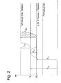
- Figure 2 shows a diagram for the interpretation of the spring force, not necessarily two springs 17; 35 can be used, but also a single spring can be sufficient.
- a solid line represents a level position Ho occupied by the vehicle body at a normal load. The normal loading can z. B. the weight of an adult person including luggage. To support this load would be a vertical load Fso necessary.
- the spring (s) have a biasing force FFS that would support the vehicle body at the level H 1 .
- the electric actuator is operated such that a force FMS against the force FFS of the spring (s) 17; 35 acts. This results in a certain power loss, which has a thermal effect and their qualitative size is to be clarified by the parabolic representation.
- the force FMS is equal to zero, so that no power loss occurs.
- the level H 1 can z. B. are exactly between the minimum and the maximum load state, but also be determined empirically.
- the force FMS of the electric actuator 19 can be reduced and the existing excess of the spring force FFS can be used.
- the force FMS may not be or only slightly larger than an unloaded vehicle.
- the mentioned power dissipation is proportional to FMS 2 , ie a doubling of the force of the actuator would result in a quadrupling of the power loss and thus the thermal load.
- the parabola with the actuator force F MSold is shown by way of example for the previous design, so that the advantage achieved is even clearer.
Landscapes
- Engineering & Computer Science (AREA)
- General Engineering & Computer Science (AREA)
- Mechanical Engineering (AREA)
- Physics & Mathematics (AREA)
- Acoustics & Sound (AREA)
- Aviation & Aerospace Engineering (AREA)
- Vehicle Body Suspensions (AREA)
- Vibration Prevention Devices (AREA)
Abstract
Description
- Die Erfindung betrifft einen Federträger gemäß dem Oberbegriff von Patentanspruch 1.
- Aus der DE 102 55 764 B3 ist Federträger bekannt, der einen E-Motor aufweist, um einen Federteller für eine Fahrzeugtragfeder in seiner axialen Position zu verstellen. Die axiale Position des Federtellers bestimmt eine Vorspannkraft der Fahrzeugtragfeder. Je höher Vorspannkraft eingestellt ist, um so kleiner ist die Einfederungsbewegung eines Fahrzeugaufbaus. Mit einem derartigen Federträger kann man eine Niveauregulierung erzielen oder einer Wank-und/oder Nickbewegung entgegenwirken.
- Bei hydraulischen oder pneumatischen Niveauregulierungen wird der energieärmste Zustand des Systems auf die Konstruktionslage bezogen. Die Konstruktionslage des Fahrzeugs entspricht beispielsweise der Beladung mit einer Person und einem Gepäckanteil. Bei Erreichen der Konstruktionslage wird beispielsweise die Pumpe für das Niveauregelsystem abgeschaltet.
- In der EP 689 21 534 T2 wird eine Kombination einer Luftfeder mit einer elektromotorischen Federverstellung beschrieben, wobei der E-Motor in Ruhelage keine Kraft ausübt. (Fig. 7). Erst bei einer Abweichung der Momentanlage von einer Konstruktionslage, die einer Beladung eines Fahrzeugs mit z. B. einer Person inkl. Gepäck entspricht, wird der E-Motor aktiviert. Prinzipbedingt steigt mit zunehmender Kraft des E-Motors auch die Verlustleistung entsprechend der Stromstärke im Quadrat. Bei einer Verdoppelung der Beladung erreicht die Verlustleistung einen vierfachen Wert. Dadurch wird die Verlustleistung zu einem wesentlichen Entscheidungskriterium bei der Auswahl des E-Motors.
- Die gattungsbildende DE 101 22 542 A1 beschreibt ein Verfahren zum Betrieb eines Federträgers zwischen einem Stützelement und einer zum Stützelement beweglichen Traglast, wobei der Federträger mindestens eine Feder aufweist, deren Vorspannkraft mittels eines elektrischen Aktuators einstellbar ist, um einen definierten Abstand der Traglast zum Stützelement zu erreichen. Die Feder soll dabei derart eingestellt sein, dass in beiden Richtungen die von dem Motor auszuübende Kraft gleich groß ist.
- Aufgabe der vorliegenden Erfindung ist es ein Verfahren zum Betrieb eines Federträgers mit elektrischer Verstellung der Federkraft zu realisieren, das eine möglichst geringe Verlustleistung für den Aktuator mit sich bringt.
- Erfindungsgemäß wird die Aufgabe dadurch gelöst, dass der elektrische Aktuator eine Kraft entgegen der Tragkraft der Feder ausübt, um den definierten Abstand zu erreichen.
- Der Vorteil dieser bewußt zu groß dimensionierten Federkraft besteht darin, dass der elektrische Aktuator bei einer zulässigen Beladung einen deutlich kleineren Stützkraftanteil aufbringen muss, um den defininierten Abstand einzuhalten, als bei einer exakt auf den definierten Abstand ausgelegte Federkraft. Zwar muss der elektrische Aktuator häufig aktiviert werden, um den definierten Abstand zwischen der Traglast und dem Stützelement zu erreichen, jedoch nicht mit den Stützkraftspitzenwerten. Die Stützkraftspitzenwerte bestimmen die auftretende Verlusteistung im elektrischen Aktuator. Wenn man die Verlustleistung minimiert, dann kann man einen leistungsschwächeren elektrischen Aktuator verwenden, der deutlich geringer thermisch beansprucht wird. Ein leistungsschwächerer Aktuator benötigt in der Regel auch einen kleineren Bauraum.
- Anhand der folgenden Figurenbeschreibung soll die Erfindung näher erläutert werden. Es zeigt:
- Fig. 1
- Prinzipdarstellung von einem Federträger mit elektrisch verstellbarer Vorspannkraft
- Fig. 2
- Kraft-Niveaulagen-Diagramm
- Die Fig. 1 zeigt ein Prinzipschaubild eines Federträgers 1, der zwei axial relativ zu einander bewegliche Baugruppen 3; 5 aufweist. Die Baugruppe 5 kann mit einer Traglast z. B. in der Ausführung eines Fahrzeugaufbaus verbunden sein. Eine erste Baugruppe 3 umfasst einen Federteller 7, der z. B. an einem Zylinder 9 eines Schwingungsdämpfers 11 befestigt ist. Die zweite Baugruppe 5 verfügt über einen Federteller 13, der mit einer Kolbenstange 15 des Schwingungsdämpfers 11 in Wirkverbindung steht. Zwischen den beiden Federtellern 7; 13 ist eine Feder 17 verspannt. Grundsätzlich kann man den Federteller 7 z. B. auch direkt an einer Fahrzeugachse als Stützelement anordnen und den oberen Federteller 13 auch ohne Kolbenstange 15 mit einem Fahrzeugaufbau in Wirkverbindung bringen, so dass die Verwendung eines koaxial angeordneten Schwingungsdämpfers für die Erfindung nicht zwingend notwendig ist.
- Die zweite Baugruppe 5 umfasst einen elektrischen Aktuator 19 in einem Gehäuse 21. Der Aktuator verfügt über einen Rotor 23 und einen Stator 25. Bezogen auf den Stator 25 stellt der Rotor 23 einen Innenläufer dar. Generell ist der konstruktive Aufbau des Federträgers untergeordnet. Nach radial innen treibt der Rotor eine Gewindespindel 27 an, die sich über ein erstes Lager 29 und ein zweites Lager 31 am Gehäuse 21 des Aktuators 19 abstützt. Die Gewindespindel verfügt am Innendurchmesser über ein Bewegungsgewinde und steht mit einer Gewindemutter 33 in Eingriff. Der Federteller 13 ist an der Gewindemutter 33 befestigt und erstreckt sich nach radial innen. Eine Drehbewegung des Rotors wird von der Gewindespindel 27 in Verbindung mit der Gewindemutter 33 in eine Axialbewegung des Federtellers 13 umgesetzt, so dass über den Aktuator die Vorspannung der Feder 17 eingestellt werden kann.
- Neben der Tragfeder 17, die zwischen dem verstellbaren Federteller 13 und dem Federteller 7 der ersten Baugruppe verspannt ist, stützt sich eine zweite Feder 35 zwischen der zweiten Baugruppe und dem axial verstellbaren Federteller 13 ab. Die zweite Feder sorgt für eine statische Entlastung des Aktuators. Bei einer Verstellbewegung des Aktuators wird die Gesamtfederrate der beiden Federn 17; 35 verändert und zur Lageregelung eines Fahrzeugs genutzt.
- Die Figur 2 zeigt ein Schaubild für die Auslegung der Federkraft, wobei nicht unbedingt zwei Federn 17; 35 verwendet werden müssen, sondern auch eine einzelne Feder ausreichen kann. Eine Volllinie steht für eine Niveaulage Ho, die von dem Fahrzeugaufbau bei einer Normalbeladung eingenommen wird. Die Normalbeladung kann z. B. dem Gewicht einer erwachsenen Person inkl. Gepäck entsprechen. Zur Abstützung dieser Last wäre eine Stützlast Fso notwendig. Die Feder(n) verfügen jedoch über eine Vorspannkraft FFS, die den Fahrzeugaufbau auf dem Niveau H1 tragen würden. Um den Fahrzeugaufbau auf den definierten Abstand zum Stützelement bzw. zur Standfläche zu bewegen, wird der elektrische Aktuator derart betrieben, dass eine Kraft FMS gegen die Kraft FFS der Feder(n) 17; 35 wirkt. Dabei fällt eine gewisse Verlustleistung an, die sich thermisch auswirkt und deren qualitative Größe durch die Parabeldarstellung verdeutlicht werden soll.
- Wenn der Fahrzeug das Niveau H1 einnimmt, ist die Kraft FMS gleich Null, so dass keine Verlustleistung anfällt. Das Niveau H1 kann z. B. exakt zwischen dem Minimal-und dem Maximalbeladungzustand liegen, jedoch auch empirisch bestimmt sein.
- Wird das Fahrzeug stärker beladen, dann kann die Kraft FMS des elektrischen Aktuators 19 reduziert und der vorhandene Überschuss der Federkraft FFS genutzt werden. Bei einem maximalen Beladungszustand des Fahrzeugs muss die Kraft FMS ggf. nicht oder nur wenig größer sein als bei einem unbeladenen Fahrzeug. Die angesprochene Verlustleistung ist proportional FMS2, d. h. eine Verdoppelung der Kraft des Aktuators würde eine Vervierfachung der Verlustleistung und damit der thermischen Belastung nach sich ziehen. In dem Schaubild ist beispielhaft für die bisherige Auslegung die Parabel mit der Aktuatorkraft FMSalt eingezeichnet, so dass der erreichte Vorteil noch deutlicher wird.
Claims (1)
- Verfahren zum Betrieb eines Federträgers zwischen einem Stützelement und einer zum Stützelement beweglichen Traglast, wobei der Federträger mindestens eine Feder aufweist, deren Vorspannkraft mittels eines elektrischen Aktuators einstellbar ist, um einen definierten Abstand der Traglast zum Stützelement zu erreichen, wobei die durch die Vorspannung der Feder erzeugte Tragkraft bei dem definierten Abstand größer ist als es für die Traglast erforderlich wäre,
dadurch gekennzeichnet,
dass der elektrische Aktuator eine Kraft (FMS) entgegen der Tragkraft (FF) der Feder (17; 35) ausübt, um den definierten Abstand (Ho) zu erreichen.
Applications Claiming Priority (1)
| Application Number | Priority Date | Filing Date | Title |
|---|---|---|---|
| DE200510001736 DE102005001736B3 (de) | 2005-01-14 | 2005-01-14 | Verfahren zum Betrieb eines Federträgers mit elektrischer Federkraftverstellung |
Publications (2)
| Publication Number | Publication Date |
|---|---|
| EP1681188A1 true EP1681188A1 (de) | 2006-07-19 |
| EP1681188B1 EP1681188B1 (de) | 2007-11-21 |
Family
ID=35955627
Family Applications (1)
| Application Number | Title | Priority Date | Filing Date |
|---|---|---|---|
| EP06000374A Revoked EP1681188B1 (de) | 2005-01-14 | 2006-01-10 | Verfahren zum Betrieb eines Federträgers mit elektrischer Federkraftverstellung |
Country Status (2)
| Country | Link |
|---|---|
| EP (1) | EP1681188B1 (de) |
| DE (2) | DE102005001736B3 (de) |
Cited By (2)
| Publication number | Priority date | Publication date | Assignee | Title |
|---|---|---|---|---|
| WO2009074199A1 (de) * | 2007-12-12 | 2009-06-18 | Bayerische Motoren Werke Aktiengesellschaft | Federbein mit stellhülse |
| WO2017097655A1 (de) * | 2015-12-08 | 2017-06-15 | Bayerische Motoren Werke Aktiengesellschaft | Vorrichtung zur höhenverstellung einer radaufhängung eines fahrzeugs, federbein mit einer vorrichtung zur höhenverstellung und fahrzeug mit einer radaufhängung mit einer vorrichtung zur höhenverstellung |
Families Citing this family (1)
| Publication number | Priority date | Publication date | Assignee | Title |
|---|---|---|---|---|
| DE102009045051B4 (de) | 2009-09-28 | 2011-09-01 | Zf Friedrichshafen Ag | Verstellbares Federbein |
Citations (6)
| Publication number | Priority date | Publication date | Assignee | Title |
|---|---|---|---|---|
| EP0363158A2 (de) * | 1988-10-05 | 1990-04-11 | Ford Motor Company Limited | Elektrisch angetriebene aktive Fahrzeugaufhängung |
| WO1991004876A1 (fr) * | 1989-10-05 | 1991-04-18 | Mauro Bianchi S.A. | Procede de suspension de roue de vehicule |
| EP0436870A2 (de) * | 1990-01-08 | 1991-07-17 | General Electric Company | Dynamisches Fahrzeugaufhängungssystem mit elektronisch kommutiertem Motor |
| DE10122542A1 (de) | 2000-07-26 | 2002-02-07 | Continental Teves Ag & Co Ohg | Vorrichtung zur Regelung von Bewegungen des Aufbaus von Kraftfahrzeugen |
| DE10120102A1 (de) * | 2001-04-25 | 2002-10-31 | Bosch Gmbh Robert | Aktives Fahrwerk mit elektrischem Aktuator und Dämpfer |
| DE10255764B3 (de) | 2002-11-28 | 2004-02-26 | Thyssenkrupp Automotive Ag | Fahrzeugfahrwerk |
-
2005
- 2005-01-14 DE DE200510001736 patent/DE102005001736B3/de not_active Revoked
-
2006
- 2006-01-10 EP EP06000374A patent/EP1681188B1/de not_active Revoked
- 2006-01-10 DE DE200650000186 patent/DE502006000186D1/de not_active Expired - Lifetime
Patent Citations (7)
| Publication number | Priority date | Publication date | Assignee | Title |
|---|---|---|---|---|
| EP0363158A2 (de) * | 1988-10-05 | 1990-04-11 | Ford Motor Company Limited | Elektrisch angetriebene aktive Fahrzeugaufhängung |
| DE68921534T2 (de) | 1988-10-05 | 1995-07-20 | Ford Werke Ag | Elektrisch angetriebene aktive Fahrzeugaufhängung. |
| WO1991004876A1 (fr) * | 1989-10-05 | 1991-04-18 | Mauro Bianchi S.A. | Procede de suspension de roue de vehicule |
| EP0436870A2 (de) * | 1990-01-08 | 1991-07-17 | General Electric Company | Dynamisches Fahrzeugaufhängungssystem mit elektronisch kommutiertem Motor |
| DE10122542A1 (de) | 2000-07-26 | 2002-02-07 | Continental Teves Ag & Co Ohg | Vorrichtung zur Regelung von Bewegungen des Aufbaus von Kraftfahrzeugen |
| DE10120102A1 (de) * | 2001-04-25 | 2002-10-31 | Bosch Gmbh Robert | Aktives Fahrwerk mit elektrischem Aktuator und Dämpfer |
| DE10255764B3 (de) | 2002-11-28 | 2004-02-26 | Thyssenkrupp Automotive Ag | Fahrzeugfahrwerk |
Cited By (3)
| Publication number | Priority date | Publication date | Assignee | Title |
|---|---|---|---|---|
| WO2009074199A1 (de) * | 2007-12-12 | 2009-06-18 | Bayerische Motoren Werke Aktiengesellschaft | Federbein mit stellhülse |
| US8256589B2 (en) | 2007-12-12 | 2012-09-04 | Bayerische Motoren Werke Aktiengesellschaft | Spring strut with control sleeve |
| WO2017097655A1 (de) * | 2015-12-08 | 2017-06-15 | Bayerische Motoren Werke Aktiengesellschaft | Vorrichtung zur höhenverstellung einer radaufhängung eines fahrzeugs, federbein mit einer vorrichtung zur höhenverstellung und fahrzeug mit einer radaufhängung mit einer vorrichtung zur höhenverstellung |
Also Published As
| Publication number | Publication date |
|---|---|
| DE502006000186D1 (de) | 2008-01-03 |
| DE102005001736B3 (de) | 2006-07-13 |
| EP1681188B1 (de) | 2007-11-21 |
Similar Documents
| Publication | Publication Date | Title |
|---|---|---|
| DE10255764B3 (de) | Fahrzeugfahrwerk | |
| DE112010005077B4 (de) | Feder-dämpfer-einheit | |
| EP2231427B1 (de) | Federbeinanordnung für radaufhängungen von kraftfahrzeugen | |
| DE112011101650B4 (de) | Feder-Dämpfer-Einheit zur Höhenverstellung eines Fahrzeuges | |
| DE69908714T2 (de) | Schraubendruckfeder für eine Fahrzeugradaufhängung | |
| DE68921534T2 (de) | Elektrisch angetriebene aktive Fahrzeugaufhängung. | |
| EP2408632B1 (de) | Aktives elektromechanisches federungssystem für ein fahrwerk eines kraftfahrzeuges | |
| EP1729985B1 (de) | Fahrzeugfahrwerk | |
| DE102016221206A1 (de) | Elektromechanischer Fahrwerksaktuator | |
| DE10122542A1 (de) | Vorrichtung zur Regelung von Bewegungen des Aufbaus von Kraftfahrzeugen | |
| EP2003002B1 (de) | Federbein für ein Kraftfahrzeug mit einem axial verstellbaren Federteller | |
| EP1681190B1 (de) | Federträger mit verstellbarem Federteller | |
| EP3736146A1 (de) | Energieversorgungseinheit für aktives fahrwerksystem | |
| DE102010036238A1 (de) | Feder-Dämpfer-Einheit zur Höhenverstellung eines Fahrzeuges | |
| EP1681188B1 (de) | Verfahren zum Betrieb eines Federträgers mit elektrischer Federkraftverstellung | |
| EP2421718B1 (de) | Vorrichtung zum abstützen einer tragfeder einer radaufhängung für ein kraftfahrzeug sowie verfahren zum einbau einer solchen vorrichtung | |
| EP1795386A1 (de) | Aktives Fahrwerk für ein Kraftfahrzeug | |
| EP0179329A2 (de) | Vorrichtung für Hebeeinrichtungen | |
| EP0501115A1 (de) | Regelbares Federungssystem für Radaufhängungen an Kraftfahrzeugen | |
| DE102018128595A1 (de) | Vorrichtung zum Verbinden eines Federbeines mit einer Karosserie | |
| DE102008005247A1 (de) | Verfahren zum Betrieb einer Sicherheitseinrichtung für einen verstellbaren Stabilisator | |
| DE102005001737A1 (de) | Federträger mit verstellbarem Federteller | |
| DE102005001735A1 (de) | Federträger | |
| WO2020038854A1 (de) | Achse eines fahrzeuges | |
| EP0418689B1 (de) | Spindel mit Einzelantrieb |
Legal Events
| Date | Code | Title | Description |
|---|---|---|---|
| PUAI | Public reference made under article 153(3) epc to a published international application that has entered the european phase |
Free format text: ORIGINAL CODE: 0009012 |
|
| 17P | Request for examination filed |
Effective date: 20060425 |
|
| AK | Designated contracting states |
Kind code of ref document: A1 Designated state(s): AT BE BG CH CY CZ DE DK EE ES FI FR GB GR HU IE IS IT LI LT LU LV MC NL PL PT RO SE SI SK TR |
|
| AX | Request for extension of the european patent |
Extension state: AL BA HR MK YU |
|
| 17Q | First examination report despatched |
Effective date: 20060918 |
|
| AKX | Designation fees paid |
Designated state(s): AT BE BG CH CY CZ DE DK EE ES FI FR GB GR HU IE IS IT LI LT LU LV MC NL PL PT RO SE SI SK TR |
|
| GRAP | Despatch of communication of intention to grant a patent |
Free format text: ORIGINAL CODE: EPIDOSNIGR1 |
|
| GRAS | Grant fee paid |
Free format text: ORIGINAL CODE: EPIDOSNIGR3 |
|
| GRAA | (expected) grant |
Free format text: ORIGINAL CODE: 0009210 |
|
| AK | Designated contracting states |
Kind code of ref document: B1 Designated state(s): AT BE BG CH CY CZ DE DK EE ES FI FR GB GR HU IE IS IT LI LT LU LV MC NL PL PT RO SE SI SK TR |
|
| REG | Reference to a national code |
Ref country code: GB Ref legal event code: FG4D Free format text: NOT ENGLISH |
|
| REG | Reference to a national code |
Ref country code: IE Ref legal event code: FG4D Free format text: LANGUAGE OF EP DOCUMENT: GERMAN |
|
| REG | Reference to a national code |
Ref country code: CH Ref legal event code: EP |
|
| REF | Corresponds to: |
Ref document number: 502006000186 Country of ref document: DE Date of ref document: 20080103 Kind code of ref document: P |
|
| PG25 | Lapsed in a contracting state [announced via postgrant information from national office to epo] |
Ref country code: ES Free format text: LAPSE BECAUSE OF FAILURE TO SUBMIT A TRANSLATION OF THE DESCRIPTION OR TO PAY THE FEE WITHIN THE PRESCRIBED TIME-LIMIT Effective date: 20080304 Ref country code: NL Free format text: LAPSE BECAUSE OF FAILURE TO SUBMIT A TRANSLATION OF THE DESCRIPTION OR TO PAY THE FEE WITHIN THE PRESCRIBED TIME-LIMIT Effective date: 20071121 Ref country code: SE Free format text: LAPSE BECAUSE OF FAILURE TO SUBMIT A TRANSLATION OF THE DESCRIPTION OR TO PAY THE FEE WITHIN THE PRESCRIBED TIME-LIMIT Effective date: 20080221 |
|
| NLV1 | Nl: lapsed or annulled due to failure to fulfill the requirements of art. 29p and 29m of the patents act | ||
| PG25 | Lapsed in a contracting state [announced via postgrant information from national office to epo] |
Ref country code: SI Free format text: LAPSE BECAUSE OF FAILURE TO SUBMIT A TRANSLATION OF THE DESCRIPTION OR TO PAY THE FEE WITHIN THE PRESCRIBED TIME-LIMIT Effective date: 20071121 Ref country code: PL Free format text: LAPSE BECAUSE OF FAILURE TO SUBMIT A TRANSLATION OF THE DESCRIPTION OR TO PAY THE FEE WITHIN THE PRESCRIBED TIME-LIMIT Effective date: 20071121 Ref country code: FI Free format text: LAPSE BECAUSE OF FAILURE TO SUBMIT A TRANSLATION OF THE DESCRIPTION OR TO PAY THE FEE WITHIN THE PRESCRIBED TIME-LIMIT Effective date: 20071121 Ref country code: IS Free format text: LAPSE BECAUSE OF FAILURE TO SUBMIT A TRANSLATION OF THE DESCRIPTION OR TO PAY THE FEE WITHIN THE PRESCRIBED TIME-LIMIT Effective date: 20080321 Ref country code: BG Free format text: LAPSE BECAUSE OF FAILURE TO SUBMIT A TRANSLATION OF THE DESCRIPTION OR TO PAY THE FEE WITHIN THE PRESCRIBED TIME-LIMIT Effective date: 20080221 Ref country code: LT Free format text: LAPSE BECAUSE OF FAILURE TO SUBMIT A TRANSLATION OF THE DESCRIPTION OR TO PAY THE FEE WITHIN THE PRESCRIBED TIME-LIMIT Effective date: 20071121 Ref country code: LV Free format text: LAPSE BECAUSE OF FAILURE TO SUBMIT A TRANSLATION OF THE DESCRIPTION OR TO PAY THE FEE WITHIN THE PRESCRIBED TIME-LIMIT Effective date: 20071121 |
|
| GBV | Gb: ep patent (uk) treated as always having been void in accordance with gb section 77(7)/1977 [no translation filed] | ||
| BERE | Be: lapsed |
Owner name: ZF FRIEDRICHSHAFEN A.G. Effective date: 20080131 |
|
| PG25 | Lapsed in a contracting state [announced via postgrant information from national office to epo] |
Ref country code: CZ Free format text: LAPSE BECAUSE OF FAILURE TO SUBMIT A TRANSLATION OF THE DESCRIPTION OR TO PAY THE FEE WITHIN THE PRESCRIBED TIME-LIMIT Effective date: 20071121 Ref country code: DK Free format text: LAPSE BECAUSE OF FAILURE TO SUBMIT A TRANSLATION OF THE DESCRIPTION OR TO PAY THE FEE WITHIN THE PRESCRIBED TIME-LIMIT Effective date: 20071121 |
|
| PG25 | Lapsed in a contracting state [announced via postgrant information from national office to epo] |
Ref country code: RO Free format text: LAPSE BECAUSE OF FAILURE TO SUBMIT A TRANSLATION OF THE DESCRIPTION OR TO PAY THE FEE WITHIN THE PRESCRIBED TIME-LIMIT Effective date: 20071121 Ref country code: SK Free format text: LAPSE BECAUSE OF FAILURE TO SUBMIT A TRANSLATION OF THE DESCRIPTION OR TO PAY THE FEE WITHIN THE PRESCRIBED TIME-LIMIT Effective date: 20071121 Ref country code: MC Free format text: LAPSE BECAUSE OF NON-PAYMENT OF DUE FEES Effective date: 20080131 |
|
| PLBI | Opposition filed |
Free format text: ORIGINAL CODE: 0009260 |
|
| PLAX | Notice of opposition and request to file observation + time limit sent |
Free format text: ORIGINAL CODE: EPIDOSNOBS2 |
|
| PG25 | Lapsed in a contracting state [announced via postgrant information from national office to epo] |
Ref country code: PT Free format text: LAPSE BECAUSE OF FAILURE TO SUBMIT A TRANSLATION OF THE DESCRIPTION OR TO PAY THE FEE WITHIN THE PRESCRIBED TIME-LIMIT Effective date: 20080421 |
|
| 26 | Opposition filed |
Opponent name: AUDI AG Effective date: 20080819 |
|
| RAP2 | Party data changed (patent owner data changed or rights of a patent transferred) |
Owner name: VOLKSWAGEN AG Owner name: ZF FRIEDRICHSHAFEN AG |
|
| REG | Reference to a national code |
Ref country code: IE Ref legal event code: FD4D |
|
| PG25 | Lapsed in a contracting state [announced via postgrant information from national office to epo] |
Ref country code: FR Free format text: LAPSE BECAUSE OF FAILURE TO SUBMIT A TRANSLATION OF THE DESCRIPTION OR TO PAY THE FEE WITHIN THE PRESCRIBED TIME-LIMIT Effective date: 20080905 Ref country code: IE Free format text: LAPSE BECAUSE OF FAILURE TO SUBMIT A TRANSLATION OF THE DESCRIPTION OR TO PAY THE FEE WITHIN THE PRESCRIBED TIME-LIMIT Effective date: 20071121 |
|
| PG25 | Lapsed in a contracting state [announced via postgrant information from national office to epo] |
Ref country code: GB Free format text: LAPSE BECAUSE OF FAILURE TO SUBMIT A TRANSLATION OF THE DESCRIPTION OR TO PAY THE FEE WITHIN THE PRESCRIBED TIME-LIMIT Effective date: 20071121 |
|
| PLBP | Opposition withdrawn |
Free format text: ORIGINAL CODE: 0009264 |
|
| PG25 | Lapsed in a contracting state [announced via postgrant information from national office to epo] |
Ref country code: EE Free format text: LAPSE BECAUSE OF FAILURE TO SUBMIT A TRANSLATION OF THE DESCRIPTION OR TO PAY THE FEE WITHIN THE PRESCRIBED TIME-LIMIT Effective date: 20071121 Ref country code: GR Free format text: LAPSE BECAUSE OF FAILURE TO SUBMIT A TRANSLATION OF THE DESCRIPTION OR TO PAY THE FEE WITHIN THE PRESCRIBED TIME-LIMIT Effective date: 20080222 |
|
| PG25 | Lapsed in a contracting state [announced via postgrant information from national office to epo] |
Ref country code: BE Free format text: LAPSE BECAUSE OF NON-PAYMENT OF DUE FEES Effective date: 20080131 |
|
| PLBB | Reply of patent proprietor to notice(s) of opposition received |
Free format text: ORIGINAL CODE: EPIDOSNOBS3 |
|
| PG25 | Lapsed in a contracting state [announced via postgrant information from national office to epo] |
Ref country code: AT Free format text: LAPSE BECAUSE OF NON-PAYMENT OF DUE FEES Effective date: 20080110 |
|
| PG25 | Lapsed in a contracting state [announced via postgrant information from national office to epo] |
Ref country code: CY Free format text: LAPSE BECAUSE OF FAILURE TO SUBMIT A TRANSLATION OF THE DESCRIPTION OR TO PAY THE FEE WITHIN THE PRESCRIBED TIME-LIMIT Effective date: 20071121 |
|
| PG25 | Lapsed in a contracting state [announced via postgrant information from national office to epo] |
Ref country code: HU Free format text: LAPSE BECAUSE OF FAILURE TO SUBMIT A TRANSLATION OF THE DESCRIPTION OR TO PAY THE FEE WITHIN THE PRESCRIBED TIME-LIMIT Effective date: 20080522 Ref country code: LU Free format text: LAPSE BECAUSE OF NON-PAYMENT OF DUE FEES Effective date: 20080110 |
|
| PG25 | Lapsed in a contracting state [announced via postgrant information from national office to epo] |
Ref country code: TR Free format text: LAPSE BECAUSE OF FAILURE TO SUBMIT A TRANSLATION OF THE DESCRIPTION OR TO PAY THE FEE WITHIN THE PRESCRIBED TIME-LIMIT Effective date: 20071121 |
|
| REG | Reference to a national code |
Ref country code: CH Ref legal event code: PL |
|
| PG25 | Lapsed in a contracting state [announced via postgrant information from national office to epo] |
Ref country code: LI Free format text: LAPSE BECAUSE OF NON-PAYMENT OF DUE FEES Effective date: 20100131 Ref country code: CH Free format text: LAPSE BECAUSE OF NON-PAYMENT OF DUE FEES Effective date: 20100131 |
|
| PG25 | Lapsed in a contracting state [announced via postgrant information from national office to epo] |
Ref country code: IT Free format text: LAPSE BECAUSE OF NON-PAYMENT OF DUE FEES Effective date: 20080131 |
|
| RAP2 | Party data changed (patent owner data changed or rights of a patent transferred) |
Owner name: VOLKSWAGEN AKTIENGESELLSCHAFT Owner name: ZF FRIEDRICHSHAFEN AG |
|
| PGFP | Annual fee paid to national office [announced via postgrant information from national office to epo] |
Ref country code: DE Payment date: 20140108 Year of fee payment: 9 |
|
| RDAF | Communication despatched that patent is revoked |
Free format text: ORIGINAL CODE: EPIDOSNREV1 |
|
| REG | Reference to a national code |
Ref country code: DE Ref legal event code: R064 Ref document number: 502006000186 Country of ref document: DE Ref country code: DE Ref legal event code: R103 Ref document number: 502006000186 Country of ref document: DE |
|
| RDAG | Patent revoked |
Free format text: ORIGINAL CODE: 0009271 |
|
| STAA | Information on the status of an ep patent application or granted ep patent |
Free format text: STATUS: PATENT REVOKED |
|
| 27W | Patent revoked |
Effective date: 20140712 |
|
| REG | Reference to a national code |
Ref country code: DE Ref legal event code: R107 Ref document number: 502006000186 Country of ref document: DE Effective date: 20150108 |
|
| REG | Reference to a national code |
Ref country code: AT Ref legal event code: MA03 Ref document number: 378960 Country of ref document: AT Kind code of ref document: T Effective date: 20140712 |