EP1681121A2 - Processing system - Google Patents
Processing system Download PDFInfo
- Publication number
- EP1681121A2 EP1681121A2 EP06250231A EP06250231A EP1681121A2 EP 1681121 A2 EP1681121 A2 EP 1681121A2 EP 06250231 A EP06250231 A EP 06250231A EP 06250231 A EP06250231 A EP 06250231A EP 1681121 A2 EP1681121 A2 EP 1681121A2
- Authority
- EP
- European Patent Office
- Prior art keywords
- measurement
- carry
- robot
- workpieces
- processing
- Prior art date
- Legal status (The legal status is an assumption and is not a legal conclusion. Google has not performed a legal analysis and makes no representation as to the accuracy of the status listed.)
- Granted
Links
Images



Classifications
-
- B—PERFORMING OPERATIONS; TRANSPORTING
- B23—MACHINE TOOLS; METAL-WORKING NOT OTHERWISE PROVIDED FOR
- B23K—SOLDERING OR UNSOLDERING; WELDING; CLADDING OR PLATING BY SOLDERING OR WELDING; CUTTING BY APPLYING HEAT LOCALLY, e.g. FLAME CUTTING; WORKING BY LASER BEAM
- B23K37/00—Auxiliary devices or processes, not specially adapted for a procedure covered by only one of the other main groups of this subclass
- B23K37/04—Auxiliary devices or processes, not specially adapted for a procedure covered by only one of the other main groups of this subclass for holding or positioning work
- B23K37/0408—Auxiliary devices or processes, not specially adapted for a procedure covered by only one of the other main groups of this subclass for holding or positioning work for planar work
-
- B—PERFORMING OPERATIONS; TRANSPORTING
- B23—MACHINE TOOLS; METAL-WORKING NOT OTHERWISE PROVIDED FOR
- B23K—SOLDERING OR UNSOLDERING; WELDING; CLADDING OR PLATING BY SOLDERING OR WELDING; CUTTING BY APPLYING HEAT LOCALLY, e.g. FLAME CUTTING; WORKING BY LASER BEAM
- B23K11/00—Resistance welding; Severing by resistance heating
- B23K11/24—Electric supply or control circuits therefor
- B23K11/25—Monitoring devices
-
- B—PERFORMING OPERATIONS; TRANSPORTING
- B23—MACHINE TOOLS; METAL-WORKING NOT OTHERWISE PROVIDED FOR
- B23K—SOLDERING OR UNSOLDERING; WELDING; CLADDING OR PLATING BY SOLDERING OR WELDING; CUTTING BY APPLYING HEAT LOCALLY, e.g. FLAME CUTTING; WORKING BY LASER BEAM
- B23K9/00—Arc welding or cutting
- B23K9/095—Monitoring or automatic control of welding parameters
-
- B—PERFORMING OPERATIONS; TRANSPORTING
- B25—HAND TOOLS; PORTABLE POWER-DRIVEN TOOLS; MANIPULATORS
- B25J—MANIPULATORS; CHAMBERS PROVIDED WITH MANIPULATION DEVICES
- B25J9/00—Program-controlled manipulators
- B25J9/0009—Constructional details, e.g. manipulator supports, bases
- B25J9/0018—Bases fixed on ceiling, i.e. upside down manipulators
Definitions
- the present invention relates to a processing system capable of efficiently and precisely processing workpieces on which processing such as welding is performed.
- Fig. 8 is a view showing a time chart for welding steel wheels for an automobile in the processing system of Fig. 1;
- a processing system 1 comprises four stages including a carry-in stage 2, a measurement stage 3, a processing stage 4, and a carry-out stage 5, that are arranged in series from the right side of the drawing.
- the optimum number of lanes of the slide device 7 in the first embodiment can be determined by the following relationships.
- the wheels 14 are measured by the measurement robot 11 to determine a coordinate system for the processing points, for example, and conveyed to the processing stage 4 by the slide device 7 and, for these wheels 14, the measurement robot 11 and the welding robots 12 are separately provided. Therefore, it is difficult to make the coordinate system determined by the measurement robot 11 identical to the coordinate system used by the welding robots 12.
- Fig. 9 is a plan view schematically showing a processing system according to a second embodiment of the present invention.
- wheels 14 are conveyed from left and right side portions to a central portion of the processing system 38 as shown in the drawing.
- Similar elements as in the first embodiment are designated by similar reference numerals as in Fig. 1 and no further explanation will be provided.
- the wheels 14 conveyed into the processing stage 4 can be simultaneously welded by the four welding robots 12 shown in the left and right side of the drawing.
Landscapes
- Engineering & Computer Science (AREA)
- Mechanical Engineering (AREA)
- Physics & Mathematics (AREA)
- Plasma & Fusion (AREA)
- Optics & Photonics (AREA)
- Robotics (AREA)
- Manipulator (AREA)
- Machine Tool Units (AREA)
- Multi-Process Working Machines And Systems (AREA)
Abstract
Description
- The present invention relates to a processing system capable of efficiently and precisely processing workpieces on which processing such as welding is performed.
- Heretofore, welding has been utilized as a process for joining a plurality of members together in a variety of fields. Automation of such welding processes has been greatly advanced and, in recent years, such a processing system has emerged that automatically welds a plurality of members together at joining portions thereof to form a workpiece (such as a steel wheel for an automobile).
- Furthermore, it is necessary for such a processing system that automatically welds a plurality of members together at joining portions thereof to form a workpiece to operate at higher speed and in more precise manner. For this reason, it is necessary for such a processing system that processing should be able to be performed with proper processing precision by measuring variations of individual workpieces using sensors, cycle time should be reduced, overall processing system costs should be reduced, etc.
- Some conventional technologies that are used to inhibit reduction in productivity at the time of manufacturing may calculate manufacturing cost by assigning parts and part data to a plurality of different facilities, such that the overall cycle times of each facility is close to the overall cycle time of the other facilities (e.g., see Japanese Unexamined Patent Application Publication No. 2002-169839 (pages 3-9, Fig. 2), Japanese Patent and Utility Model Gazette).
- In some conventional technologies, a plurality of different manufacturing lines are provided to manufacture sub-wire-harnesses for the purpose of suppressing their interim inventories as much as possible. The manufacturing lines are managed on a line by line basis to control their cycle times (e.g., see Japanese Unexamined Patent Application Publication No. HEI 11-339572 (pages 2-3, Fig. 1), Japanese Patent and Utility Model Gazette).
- A number of conventional technologies may use touch sensing technologies to compensate for the deviation of position of a workpiece (e.g., see Japanese Unexamined Patent Application Publication Nos. 2003-285164 (page 4), 2003-53535 (page 4), and 2000-225467 (
page 3, Figs. 2, 3), Japanese Patent and Utility Model Gazette). Some conventional technologies may use a welding torch to perform touch sensing by modifying a support for a welding wire (e.g., see Japanese Unexamined Patent Application Publication No. HEI 11-254142 (page 3, Fig. 1), Japanese Patent and Utility Model Gazette). Some conventional technologies may attempt to use a tungsten electrode used for arc welding as a touch sensing probe (e.g., see Japanese Unexamined Patent Application Publication No. HEI 09-216059 (pages 2-3, Figs. 3, 4), Japanese Patent and Utility Model Gazette). - However, in Japanese Unexamined Patent Application Publication No. 2002-169839, the accumulated cycle times of each facility is made to be close to cycle times of the other facilities for the purpose of calculating a manufacturing cost. In Japanese Unexamined Patent Application Publication No. HEI 11-339572, the manufacturing lines are managed on a line by line basis to control their cycle times for the purpose of suppressing their interim inventories as much as possible. Unlike the present invention, none of these conventional technologies provide a slide device including a plurality of lanes, and a measurement stage and a processing stage for the slide device for the purpose of optimizing cycle time on a workpiece-by-workpiece basis.
- While some conventional technologies discussed above use touch sensing, unlike the present invention, none of them use touch sensing to create a compensation table so as to enable high-precision processing.
- As described above, none of the conventional technologies discussed above measure variations of individual workpieces and then operate a measuring device and a processing device efficiently by considering processing precision, overall system cost, reduction of time required for tooling change, etc.
- Therefore, an object of the present invention is to provide a processing system capable of efficiently handling workpieces and operating a measurement instrument and a processing device.
- A processing system according to the present invention includes: a carry-in stage including a carry-in device for carrying in workpieces; an operation stage in which the workpieces are measured and processed, the operation stage being disposed in series with the carry-in stage and including a measurement device and a processing device, in this order, from a carry-in stage side thereof, the measurement device being separated from the processing device; a carry-out stage disposed in series with the operation stage and including a carry-out device for carrying out the workpieces; a slide device disposed between the measurement device and the processing device of the operation stage, the slide device including a plurality of lanes, the plurality of lanes being respectively provided with fixing jigs movable back and forth; and a controller configured to perform control such that the carry-in device sequentially moves the workpieces onto the respective fixing jigs, the fixing jigs are moved along the slide device, the measurement device measures workpiece measurement portions of the workpieces and the processing device processes the workpiece measurement portion, and thereafter the carry-out device carries the workpieces out. In this embodiment, the fixing jigs provided on the plurality of lanes are moved back and forth between the measurement stage and the processing stage, the workpieces fixed to the fixing jigs are efficiently conveyed, and the processing device and the measurement device are efficiently operated. Therefore, cycle time can be reduced while high precision processing is maintained.
Furthermore, if some of the fixing jigs fail, the processing can be continued by conveying the workpieces along the slide device using the remaining fixing jigs. - In the processing system according to the present invention, the measurement device may be comprised of one measurement sensor and one measurement robot. In this embodiment, only one robot makes measurements at a plurality of slide devices and merely needs to change measurement points when the workpieces are changed, resulting in further cost savings.
- The processing system according to the present invention may further include: an input inspection device provided in the carry-in stage, for inspecting and determining positions of the workpieces and an output inspection device provided in the carry-out stage, for inspecting the workpieces, wherein the carry-in device is comprised of a carry-in robot, the carry-out device is comprised of a carry-out robot, the workpieces are carried onto the fixing jigs from the input inspection device by the carry-in robot, the workpieces are carried onto the output inspection device from the fixing jigs by the carry-out robot. In this embodiment, carrying onto and out from the plurality of slide devices, checking the workpieces and determining the positions of the workpieces as the workpieces are carried in, and inspecting the processing results of the workpieces as the workpieces are carried out can be automated. Furthermore, changing a grip position when the type of workpiece is changed can be automated.
- The processing system according to the present invention may further include a shield device provided between the measurement device and the processing device. In this embodiment, the measurement device in the measurement stage is separated from the processing device in the processing stage to thereby eliminate negative influences of vibrations, light, noises, and dusts that may otherwise be transferred between the measurement device and the processing device.
- In the processing system according to the present invention, the processing device may be comprised of a welding robot, including an error measurement system configured to measure a position error between measurement point data of the workpiece measurement portion measured by the measurement robot and the workpiece measurement portion prior to welding. A controller associated with the welding robot may be configured to create a compensation table from error data measured by the error measurement system. The processing system may further include a compensation-based driving device for operating the welding robot based on the compensation table. In this embodiment, welding can be performed accurately by the welding robot based on the compensation table created from the position error between the measurement point data of the work measurement portion.
- In the processing system according to the present invention, the processing device may be comprised of a welding robot configured to be controlled by the controller, the welding robot including an error measurement system and the controller including a position data generation system, wherein the position data generation system is configured to generate new position data by controlling the welding robot so as to slightly change a position and an orientation of the welding robot, separately, based on the measurement point data of the workpiece measurement portion measured by the measurement robot, and wherein the error measurement system is configured to measure a position error of the welding robot which is included in position data generated by the position data generation system, and wherein the controller is configured to create a compensation table from error data measured by the error measurement device. The processing device may further include a compensation-based driving device configured to operate the welding robot based on the compensation table. In this embodiment, welding can be performed accurately by the welding robot based on the compensation table created from the data in the vicinity of the actual work measurement portion.
- In the processing system according to the present invention, the error measurement system may be comprised of a touch sensing device including a tip end of the welding robot and/or a visual recognition device including a visual sensor. In this embodiment, more accurate compensation can be performed.
- In the processing system according to the present invention, the controller associated with the welding robot may be configured to create a compensation table for the workpiece measurement portion using input received from the welding robot operating on a model workpiece identical to the workpieces to be processed. In this embodiment, the model workpiece which is identical in dimension to the workpieces and whose measurement portion is accurately finished can be used to reduce the time required to create a compensation table and improve the accuracy of the compensation table.
- In the processing system according to the present invention, the workpieces may be steel wheels for an automobile, the input inspection device may be configured to inspect each of the workpieces and determine a position of each workpiece based on a valve hole or a shape of each workpiece, and the output inspection device may be configured to detect whether or not a break caliper hits the wheel. In this embodiment, welding the wheels can be automated while maintaining high accuracy and reducing cycle time.
- Preferred embodiments of the present invention will now be described by way of example only and with reference to the accompanying drawings in which:
- Fig. 1 is a plan view schematically showing a processing system according to a first embodiment of the present invention;
- Fig. 2 is a front view showing the processing system in Fig. 1;
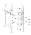
- Fig. 3 is a cross sectional view taken along line III-III of Fig. 2;
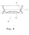
- Fig. 4 is a cross sectional view showing an example of a steel wheel for an automobile to be welded with the processing system shown in Fig. 1;
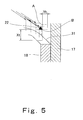
- Fig. 5 is a schematic view showing a manner in which welding points are detected by touch sensing in the processing system according to the present invention;
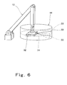
- Fig. 6 is a schematic view showing a manner in which welding points are detected by a visual sensor in the processing system according to the present invention;
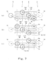
- Fig. 7 is a schematic plan view showing a flow of steel wheels for an automobile transferred in the processing system of Fig. 1;
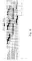
- Fig. 8 is a view showing a time chart for welding steel wheels for an automobile in the processing system of Fig. 1; and
- Fig. 9 is a plan view schematically showing a processing system according to a second embodiment of the present invention.
- Hereinbelow, embodiments of the present invention will be described with reference to the drawings. Fig. 1 is a plan view schematically showing a processing system according to a first embodiment of the present invention, Fig. 2 is a front view showing the processing system of Fig. 1, Fig. 3 is a cross sectional view taken along line III-III of Fig. 2, and Fig. 4 is a cross sectional view showing an example of a steel wheel for an automobile to be welded using the processing system. In the following embodiments, a steel wheel for an automobile shown in Fig. 4 is employed as an example of a workpiece, and an example in which two members including a
rim 17 on which a tire is to be mounted and adisc 18 to be attached to a car body are joined together by welding will be described. Of course, the workpiece is not limited to a wheel. Furthermore, another example in which an operation stage is divided into a measurement stage and a processing stage will also be described. - As shown in the drawing, a
processing system 1 comprises four stages including a carry-instage 2, ameasurement stage 3, aprocessing stage 4, and a carry-outstage 5, that are arranged in series from the right side of the drawing. Aslide device 7, which includes threelanes measurement stage 3 and theprocessing stage 4. While the present example of theslide device 7 includes threelanes jigs lanes robot 10 described below sequentially carries thewheels 14 ontorespective fixing jigs fixing jigs slide device 7, ameasurement robot 11 described below measures workpiece measurement portions, awelding robot 12 described below welds the workpiece measurement portions, and thereafter a carry-out robot 13 carries thewheels 14 out. Thecontroller 9 can be comprised of a personal computer or other suitable computing device for example. While a central controller is depicted, it will be appreciated that the control functions described herein alternatively may be divided among a plurality of distributed controllers assigned to the various components of theprocessing system 1. For example, one controller may control all welding robots, each welding robot may have its own controller, etc. - Furthermore, in this embodiment, the carry-in
robot 10 serves as a carry in device in the cary-instage 2, themeasurement robot 11 serves as a measurement device in themeasurement stage 3, thewelding robot 12 serves as a processing device in theprocessing stage 4, and the carry-outrobot 13 serves as a carry-out device in the carry-outstage 5. Thus, in this embodiment, each of thewheels 14 is forwarded from right to left in the drawing, and, at each of the stages, is transferred, measured, or processed by one of therobots 10 to 13. - The carry-in stage is provided with a
conveyer 15 for conveying thewheels 14 and aninput inspection device 16 for inspecting position information ofwheels 14 carried in by theconveyer 15. Theinput inspection device 16 is configured to inspect the position of a valve hole (air inlet hole) of each of thewheels 14 using a light sensor. Based on the position of the valve hole, a coordinate system of the wheel as carried in (for example, a rotational angle, a positional deviation of the wheel with respect to a reference point, etc.) is determined. Theinput inspection device 16 may be any suitable device that is capable of detecting a reference position of a coordinate system of a workpiece. - Thereafter, the
wheels 14 for which the coordinate systems were determined are carried by the carry-inrobot 10 provided in the carry-instage 2 and placed onto the fixingjigs slide device 7 in themeasurement stage 3. The carry-inrobot 10, is typically an articulated robot capable of carrying thewheels 14 from theinput inspection device 16 and placing thewheels 14 onto any of the plurality of fixingjigs robot 10 is provided with agrip 19 capable of handling awheel 14, with thewheel 14 being kept flat as illustrated in Fig. 4. - The
measurement stage 3 is provided with themeasurement robot 11 for measuring a coordinate system of each of thewheels 14 carried onto one of the plurality of the fixingjigs wheel 14 kept in a predetermined orientation. In this example, alaser sensor 20 is provided on a tip of an arm of themeasurement robot 11, and a coordinate system of thewheel 14 determined by thelaser sensor 20 is inputted into thecontroller 9. Themeasurement robot 11 can also be an articulated robot. - The coordinate system of the
wheel 14 determined by themeasurement robot 11 is used in determining processing points (corresponding to workpiece measurement portions) in thenext processing stage 4. Thewheels 14 measured by themeasurement robot 11 are conveyed to theprocessing stage 4 by the fixingjigs - In this embodiment, the measurement device in the
measurement stage 3 is comprised of onemeasurement robot 11 with alaser sensor 20, thereby enabling simultaneous measurements at a plurality oflanes - The
processing stage 4 is provided with fourwelding robots 12 for welding thewheels 14. In this embodiment, two of the welding robots are located in the left and right sides of the slide device 7 (i.e., vertically shown in Fig. 1) and the remaining two welding robots are located along a sliding direction of the slide device 7 (i.e., horizontally shown in Fig. 1). Thesewelding robots 12 are configured to be able to perform four welding operations simultaneously by extending theirarms 21 to any locations at the threelanes slide device 7. These welding robots can also be articulated robots. Each of the welding robots is provided with a welding torch at a tip end thereof. With these fourwelding robots 12 provided, welding can be performed by any of thewelding robots 12 onto any of therespective wheels 14 fixed to the fixingjigs wheel 14 has four spots to be welded, these welding operations can be started simultaneously and ended simultaneously, leading to reduction of processing time. - As shown in Fig. 2, the
measurement robot 11 provided in themeasurement stage 3 and thewelding robots 12 provided in theprocessing stage 4 are located onseparate stands measurement robot 11 and thewelding robots 12 on the separate stands 23, 24 prevents any vibrations generated by thewelding robots 12 at the time of processing from being transmitted to themeasurement robot 11, thereby easing negative influences on the measurement operations of themeasurement robot 11. - A
shield device 25 for shielding between themeasurement robot 11 and thewelding robots 12 is provided between themeasurement robot 11 and thewelding robots 12. The shieldingdevice 25 includes acurtain 26 extending to a location above thewheel 14. Thecurtain 26 prevents spatter, etc. from falling toward a side on which themeasurement robot 11 is positioned at the time of welding. - In addition to the above-described easing of negative effects of the vibrations of the
welding robots 12 on themeasurement robot 11, by providing themeasurement robot 11 and thewelding robots 12 on separate structures and providing theshielding device 25 between themeasurement robot 11 and thewelding robots 12, the negative effects of light, noises, spatter, etc., at the time of welding on themeasurement robot 11 are mitigated. - In the
processing stage 4, ashielding device 27 is provided at an approximate center between thewelding robots 12 arranged in the sliding direction of theslide device 7. The shieldingdevice 27 is provided with aspatter cover 28 capable of moving up and down at an approximate center of thewheel 14. This spatter cover 28 can be moved down to an approximate middle of thewheel 14 to prevent spatter from falling down from a welding portion and adhering to an attachment surface or an ornamental surface of thewheel 14. - The
slide device 7 is provided with threelanes lanes jigs jigs lanes - Each of the fixing
jigs wheel 14 serving as the workpiece, with thewheel 14 being kept flat. In this embodiment, since the workpiece is awheel 14, each of the fixingjigs 8a; 8b, 8c also has a function of rotating awheel 14 in a horizontal plane. Theslide device 7 is provided with, for example, position sensors along theslide device 7 at predetermined positions for detecting positions of the fixingjigs controller 9 is configured to perform control such that the fixingjigs - A cycle of moving the fixing
jigs lanes jigs processing system 1 to be reduced. - With the
slide device 7 comprising the plurality oflanes jigs jigs lanes slide device 7 fail, the workpieces can be continuously processed by using the remaining fixingjigs lanes slide device 7. - The optimum number of lanes of the
slide device 7 in the first embodiment can be determined by the following relationships. - The number of lanes is set to "2" if the conveying time is relatively short such as, for example:
- 1. if X ≈ Y + Z (i.e. X is approximately equal to Y+Z, which occurs, for example, when measurement time is long and approximately equal to processing time + conveying time required (for carrying-in + sliding movement + carrying-out)), or
- 2. if Y ≈ X + Z (i.e. Y is approximately equal to X+Z, which occurs, for example, when processing time is long and approximately equal to measurement time + conveying time required (for carrying-in + sliding movement + carrying-out)),
- The number of lanes is set to "3" if X, Y, and Z are substantially equal to each other such as, for example:
- 3. if X ≈ Y ≈ Z (measurement time is approximately equal to processing time, which is approximately equal to conveying time required (for carrying-in + sliding movement + carrying-out)). The closer the above equality relationship is to true, the higher the efficiency is.
- The number of lanes is set to an integer close to "2p + 2" if the conveying time is relatively long such as, for example:
- 4. if p(X + Y) ≈ Z (p >= 1) (i.e. conveying time required for (carrying-in + sliding movement + carrying-out) is longer than measurement time + processing time). The closer the above equality relationship is to true, the higher the efficiency is. For example, the number of lanes = (2p + 2) = 4 if p = 1. The number of lanes = (2p + 2) = 5 if p = 1.5. The number of lanes = (2p + 2) = 6 if p = 2. The number of lanes = (2p + 2) = 7 if p = 2.5. The number of lanes = (2p + 2) = 8 if p = 3.
- In the manner described above, the number of lanes are determined. In the first embodiment, the number of lanes is determined to be three
lanes - Once the number of lanes is determined, a cycle time of each stage is adjusted such that an optimum operation time is allocated thereto, thereby allowing dead time to be reduced. In this manner, the number of lanes can be efficiently determined and time can be efficiently allocated.
- The carry-out
stage 5 is provided with the carry-outrobot 13 capable of carrying outwheels 14 processed in theprocessing stage 4 from an end of theslide device 7. The carry-outrobot 13, is typically an articulated robot that is capable of carrying out any of thewheels 14 fixed to the plurality of fixingjigs output inspection device 29. Each of thewheels 14 carried out onto theoutput inspection device 29 is inspected to determine whether or not a break caliper hits thewheel 14. Upon completion of inspection by theoutput inspection device 29, thewheels 14 are conveyed out by aconveyor 30. Theoutput inspection device 29 may be any device that is capable of inspecting, measuring, and finishing an inspected portion of a workpiece. - Like the carry-in
robot 10 in the carry-instage 2, the carry-out device in the carry-outstage 5 is comprised of an articulated robot, such that the number of devices necessary for carrying out the workpieces from the plurality oflanes - Fig. 5 is a schematic view showing a manner in which welding points are detected by touch sensing in the processing system according to the present invention, and Fig. 6 is a schematic view showing a manner in which welding points are detected by a visual sensor in the processing system according to the present invention.
- As described above, the
wheels 14 are measured by themeasurement robot 11 to determine a coordinate system for the processing points, for example, and conveyed to theprocessing stage 4 by theslide device 7 and, for thesewheels 14, themeasurement robot 11 and thewelding robots 12 are separately provided. Therefore, it is difficult to make the coordinate system determined by themeasurement robot 11 identical to the coordinate system used by thewelding robots 12. - As shown in the drawings, the
welding robots 12 are each provided with a final position error determination system (also referred to as final position error determination means) for determining a coordinate systems of aworkpiece measurement portion 31 to be finally processed with respect to the coordinate system determined by themeasurement robot 11 before a welding operation is performed by thewelding robots 12. - One embodiment of the final position error determination system may comprise an error measurement device (also referred to as an error measurement means) of a
welding robot 12 for measuring errors between desired points and points actually reached by thewelding robot 12 when thewelding robot 12 is driven in a prescribed orientation to perform processing based on a plurality of measurement point data at which a welding robot is configured to perform processing measured in themeasurement stage 3, a driving device also referred to as a driving means) configured to drive thewelding robot 12 based on a plurality of measurement point data at which a welding robot is configured to perform processing to sequentially measure the errors, a compensation table created by the controller associated with the welding robot for storing compensation data corresponding to the robot positions calculated from the error data measured by the error measurement device, wherein the driving device is a compensation-based driving device (compensation-based driving means) configured to precisely operate thewelding robot 12 based on a plurality of measurement point data at which a welding robot is configured to perform processing and using the compensation table. It will be understood that "driving" is used herein to mean moving or actuating the welding robot and that the driving device may be implemented by the controller and configured to send signals to the welding robot to "drive" or actuate the robot. - Another embodiment of the final position error determination system (final position error determination means) may comprise a position data generation device (position data generation means) for newly generating a plurality of measurement point data based on which a welding robot is driven by slightly changing or adjusting a tip end position of the
welding robot 12 in a predetermined direction while keeping a tool orientation of awelding robot 12 unchanged, a driving device (driving means) configured to drive thewelding robot 12 based on the measurement point data, an error measurement device (error measurement means), a compensation table created by the controller associated with the welding robot for storing compensation data corresponding to robot positions calculated from the error data measured by the error measurement device, wherein the driving device is a compensation-based driving device (compensation-based driving means) for precisely operating thewelding robot 12 based on a plurality of measurement point data at which a welding robot is configured to perform processing and using the compensation table. - Another embodiment of the final position error determination device (final position error determination means) may comprise an error measurement device (error measurement means) of a welding robot 12 for measuring errors between desired points and points actually reached by the welding robot 12 by slightly changing a tool orientation of the welding robot 12 in a predetermined direction while keeping a tip end of the welding robot 12 unchanged, a driving device (driving means) for driving the welding robot 12 based on a plurality of measurement point data at which a welding robot is configured to perform processing to sequentially measure the errors, a position data generation system (position data generation means) for newly generating a plurality of measurement point data based on which a welding robot is driven by slightly changing the tip end of the welding robot 12 in a predetermined direction while keeping a tool orientation of the welding robot 12 unchanged, wherein the driving device (driving means) is configured to drive the welding robot 12 based on the measurement point data, an error measurement device (error measurement means) for measuring errors, and a compensation table created by the controller for storing compensation data corresponding to the robot positions calculated from the error data measured by the error measurement device, wherein the driving device is a compensation-based driving device (compensation-based driving means) for precisely operating the welding robot 12 based on a plurality of measurement point data at which a welding robot is configured to perform processing and using the compensation table.
- In the above embodiment, as the final position error determination system, touch sensing detection that utilizes a
welding torch 22 provided at the tip end of thewelding robot 12, and a visual recognition detection that utilizes a visual sensor provided at the tip end of thewelding robot 12 may be employed, as described below. - In the touch sensing detection embodiment shown in Fig. 5, a relative relationship between a wheel coordinate system (portion A) represented by a coordinate system determined by the
measurement robot 11 in themeasurement stage 3 and a wheel coordinate system (portion B) represented by a coordinate system of thewelding robot 12 will be predetermined by calculation using a model workpiece. - The
welding robot 12 converts values actually measured in the measurement stage 3 (reference points for touch sensing) based on the relative relationship, and when the welding robot is driven, final position errors are obtained by touch sensing as operation paths (Xt, Yt) (in this example, starting from portion B). In the touch sensing, an actual coordinate system is obtained by abutting a tip end of awelding torch 22 having a pre-set coordinate point to awheel 14 using awelding robot 12. In this manner, errors are measured by touch sensing. With the touch sensing thus performed, groove precision can be compensated for, accurately, to the order of a fraction of a millimeter. - The final position errors thus obtained can be applied to later processing by creating an error compensation table from the operation paths (Xt, Yt). Use of touch sensing to determine and compensate for errors between actual positions and calculated positions enables highly precise compensation data to be tabulated. This compensation table is newly created when the type of workpiece is changed.
- Furthermore, use of the touch sensing enables a compensation table to be created precisely and simply, thereby improving processing precision, even if the
measurement robot 11 and thewelding robots 12 are provided separately from each other. - The processing precision can be further improved by creating not only a compensation table for a typical processing movement at a processing point (workpiece measurement portion) but also a compensation table for slightly different positions in a vicinity thereof.
- On the other hand, as shown in Fig. 6, the final position error determination system may be provided in the form of a
visual sensor 32. Instead of thewelding torch 22 of thewelding robot 12 in the welding stage, thevisual sensor 32, whose field of view is within a vicinity of a position of a tip end of the tool, is provided on thewelding robot 12. A compensation table is created for slightly varying positions of the tip end of the tool of thewelding robot 12. - Where arc welding, for example, is performed by the
above welding robot 12, a time required to create a compensation table can be significantly shortened if thevisual sensor 32 serving as an error measurement device (error measurement means), whose field of view is within a vicinity of a position of the tip end of the tool of thewelding robot 12, can be reproducibly and detachably attached to the tip end of the tool of thewelding robot 12, if touch sensing is used only for the purpose of the calibration of the tip end of the tool, and ifposition information 33 of thevisual sensor 22 is used for the error measurement. Thevisual sensor 22 may be calibrated using touch sensing. - Although touch sensing is precise, such measurements take a long time. Therefore, use of a
visual sensor 32 calibrated using touch sensing enables creation of a compensation table that is as precise as that obtained by touch sensing at high speed. - Use of a model workpiece having a size identical to that of an actual workpiece and a measurement portion finished precisely for creation of a compensation table enables the measurement precisions of the touch sensing and the visual sensor to be improved, the creation time of the compensation table to be shortened, and the compensation table to be created more precisely.
- The above embodiment ensures processing accuracy while providing the advantage of eliminating negative influences that may be transferred between the measurement and the processing due to the separation of the
measurement robot 11 and thewelding robots 12. - Fig. 7 is a schematic plan view showing a flow of steel wheels for an automobile conveyed in the processing system of Fig. 1. Vertical dot dashed lines shown in the drawing indicate the positions of "carry-in," "measurement," "welding," and "carry-out" from a right side of the drawing. The
wheels 14 are continuously processed in this order by theprocessing system 1. Hereinafter, description will be provided with reference to reference numerals in Fig. 1. - As shown in the drawing, the
wheels 14 conveyed into the carry-instage 2 are each carried by the carry-inrobot 10 onto one of fixingjigs respective lanes slide device 7, in this order from top to bottom. Thewheels 14 are conveyed by the fixingjigs measurement stage 3 along theslide device 7, where a workpiece measurement portion of each of thewheels 14 is measured by themeasurement robot 11. Upon completion of the measurement, thewheels 14 are conveyed to aprocessing stage 4 along theslide device 7, where predetermined welding is performed by weldingrobots 12 to thewheels 14. Upon completion of the welding, thewheels 14 are sequentially conveyed to the carry-outstage 5, where thewheels 14 are carried out by the carry-outrobot 13 from the carry-outstage 5. Measurements and processing are sequentially performed by repeating the above described steps in the order of (a), (b), and (c) in Fig. 7, thereby allowing thewheels 14 to be continuously conveyed and processed using the 3lanes - The above operations as well as the inspection of processing results can be automated. Furthermore, when the workpiece is changed, position changes can be done quickly and inexpensively.
- Consequently, the measurement device and the processing devices are efficiently operated to thereby reduce cycle time, and the number of fixing
jigs jigs - Fig. 8 is a view showing a time chart for welding steel wheels for an automobile in the processing system of Fig. 1. Hereinafter, an example in which
steel wheels 14 for an automobile are welded by thewelding robots 12 will be described. In the example, thewheels 14 are welded using theslide device 7 including the above described threelanes lanes - As shown in the drawing, the operations of "workpiece feed," "valve hole detection," "carry-in by carry-in robot," "
lane 6a: measurement, welding," "lane 6b: measurement, welding," "lane 6c: measurement, welding," "carry-out by carry-out robot," and "caliper hit inspection" are performed in this order fromlane 6a to lane 6b to lane 6c. - One block shown in the drawing represents approximately 1 second. According to the
processing system 1, a cycle time of the caliper hit inspection can be set to 6 seconds as shown in the bottom of the drawing. - Therefore, arc-welding of the
steel wheels 14 for an automobile according to this time chart provides for a high speed and high precision processing system capable of achieving a cycle time of 6 seconds for the caliper hit inspection, for example, and thus makes it apparent that operation efficiency can be significantly improved even though the measurement device and the processing devices are provided separately from each other. - Fig. 9 is a plan view schematically showing a processing system according to a second embodiment of the present invention. In the second embodiment,
wheels 14 are conveyed from left and right side portions to a central portion of theprocessing system 38 as shown in the drawing. Similar elements as in the first embodiment are designated by similar reference numerals as in Fig. 1 and no further explanation will be provided. - As shown in the drawing, in the second embodiment, carry-in and carry-out
stages 34 are located in left and right sides of the drawing andmeasurement stages 3 are respectively located inside the carry-in and carry-outstages 34, and aprocessing stage 4 is located between the measurement stages 3.Slide devices 7 are respectively provided between one of the measurement stages 3 and theprocessing stage 4 and between the other of the measurement stages 3 and theprocessing stage 4. In this embodiment, the left and rightside slide devices 7 are each comprised of one oflanes slide devices 7 comprising the left andright side lanes - The carry-in and carry-out
stages 34 are respectively provided with carry-in and carry-outrobots 35 which are respectively carry-in and carry-out devices, the measurement stages 3 are provided with the measurement robots which are measurement devices, and the processing stage is provided with thewelding robots 12 which are processing devices. These cany-in and carry-outrobots 35,measurement robots 11, andwelding robots 12 are arranged so as to sequentially measure andweld wheels 14 conveyed inwardly and alternately by the left and right side slide devices. These carry-in and carry-outrobots 35,measurement robots 11, andwelding robots 12 are controlled such that the right side and the left side operate in a coordinated manner.Reference numeral 36 designates input and output inspection devices, each of which has both functions of theinput inspection device 16 and theoutput inspection device 29 of the first embodiment. - In the above embodiment, a
shielding device 27 is provided between the left and rightside slide devices 7, and shieldingdevices 25 are also respectively provided between one of the measurement stages 3 and theprocessing stage 4 and between the other of the measurement stages 3 and theprocessing stage 4. - In the above embodiment, like the first embodiment, a final error determination system (final error determination means) for determining final positional errors of a
workpiece measurement portion 31 from a coordinate system determined in each of themeasurement stage 3 and a coordinate system determined in theprocessing stage 4 is provided. Since the structures of the final error determination system are identical to the structures of the first embodiment, no further explanation will be provided. - According to the
processing system 38 of the second embodiment constructed as described above,wheels 14 are welded in a manner described below. -
Wheels 14 carried into the carry-in and carry-outstages 34 from the left and right sides of the drawing are inspected by the input andoutput inspection devices 36 to determine the positions of valve holes thereof, which in turn determine coordinate systems thereof as thewheels 14 are carried in. Thesewheels 14 are carried by the carry-in and carry-outrobots 35 and placed onto fixingjigs slide devices 7. Thewheels 14 carried and placed onto these fixingjigs measurement robots 11 in themeasurement stage 3 to determine coordinate systems of workpiece measurement portions thereof, then conveyed to theprocess stage 4, and welded by thewelding robots 12. Like the first embodiment, a compensation table for final position errors is created and the coordinate system for processing points is modified. - In the above embodiment, the
wheels 14 conveyed into theprocessing stage 4 can be simultaneously welded by the fourwelding robots 12 shown in the left and right side of the drawing. - The
wheels 14 thus welded are conveyed back into the measurement stages 3 from theprocessing stage 4 by theslide devices 7. Thewheels 14 conveyed back to ends of the measurement stages 3 are carried out onto the input andoutput inspection devices 36 by the carry-in and carry-outrobots 13. Thewheels 14 carried out onto the input andoutput inspection devices 36 are inspected to determine whether or not a caliper hits thewheels 14. Upon completion of the inspection, thewheels 14 are conveyed out by carry-in and carry-outconveyors 37. - In the second embodiment, operations between the left and right sides of the processing system as shown in the drawing are progressed in a coordinated manner. The
wheels 14 are sequentially conveyed into theprocessing stage 4, welded by thewelding robots 12, and conveyed into the measurements stages 3. After thewheels 14 are carried out from the input andoutput inspection devices 36,new wheels 14 are carried onto the input andoutput inspection devices 36, conveyed for welding, and so on. In the second embodiment, even if one of the left and right fixingjigs slide devices 7. - Determination of which embodiment of the processing system (
processing system 38 as in the second embodiment or theprocessing system 1 as in the first embodiment) should be employed depends on the conditions such as installation space, the type of workpiece, etc. - In the above embodiments, a
steel wheel 14 for an automobile is employed as an example of the workpiece, however, it will be appreciated that the workpiece need not be limited to a steel wheel for an automobile. - Numerous modifications and alternative embodiments of the invention will be apparent to those skilled in the art in view of the forgoing description. Accordingly, the description is to be construed as illustrative only, and is provided for the purpose of teaching those skilled in the art the best mode of carrying out the invention. The details of the structure and/or function may be varied substantially without departing from the scope of the invention.
Claims (9)
- A processing system comprising:a carry-in stage including a carry-in device for carrying in workpieces;an operation stage in which the workpieces are measured and processed, the operation stage being disposed in series with the carry-in stage, and including a measurement device and a processing device in this order from a carry-in stage side thereof, the measurement device being separated from the processing device;a carry-out stage disposed in series with the operation stage and including a carry-out device for carrying out the workpieces;a slide device disposed between the measurement device and the processing device of the operation stage, the slide device including a plurality of lanes, the plurality of lanes being respectively provided with fixing jigs movable back and forth; anda controller configured to perform control such that the carry-in device sequentially moves the workpieces onto the respective fixing jigs, the fixing jigs are moved along the slide device, the measurement device measures a workpiece measurement portion of each of the workpieces and the processing device processes each of the workpiece measurement portions, and thereafter the carry-out device carries the workpieces out.
- The processing system according to Claim 1, wherein the measurement device is comprised of one measurement sensor and one measurement robot.
- The processing system according to Claim 2, further comprising:an input inspection device provided in the carry-in stage, configured to inspect,and determine positions of the workpieces: andan output inspection device provided in the carry-out stage, configured to inspect the workpieces,wherein the carry-in device is comprised of a carry-in robot, the carry-out device is comprised of a carry-out robot, the workpieces are carried onto the fixing jigs from the input inspection device by the carry-in robot, and the workpieces are carried onto an output inspection device from the fixing jigs by the carry-out robot.
- The processing system according to Claim 3, wherein the workpieces are steel wheels for an automobile, the input inspection device is configured to inspect each of the workpieces and determine a position of each workpiece based on a valve hole or a shape of each workpiece, and the output inspection device is configured to detect whether or not a break caliper hits the wheel.
- The processing system according to Claim 2, 3 or 4, wherein the processing device is comprised of a welding robot; and
wherein the welding robot includes an error measurement system configured to measure a position error between measurement point data of the workpiece measurement portion measured by the measurement robot and the workpiece measurement portion prior to welding;
wherein the controller is configured to create a compensation table from error data measured by the error measurement system; and
wherein the processing system further includes a compensation-based driving device for operating the welding robot based on the compensation table. - The processing system according to Claim 2, 3 or 4, wherein the processing device is comprised of:a welding robot configured to be controlled by the controller, the welding robot including an error measurement system and the controller including a position data generation system, wherein the position data generation system is configured to generate new position data by controlling the welding robot so as to slightly adjust a position and an orientation of the welding robot, separately, based on the measurement point data of the workpiece measurement portion measured by the measurement robot, and wherein the error measurement system is configured to measure a position error of the welding robot which is included in position data generated by the position data generation system, and wherein the controller is configured to create a compensation table from error data measured by the error measurement device; anda compensation-based driving device configured to operate the welding robot based on the compensation table.
- The processing system according to Claim 5 or 6, wherein the error measurement system is comprised of a touch sensing device including a tip end of the welding robot and/or a visual recognition device including a visual sensor.
- The processing system according to Claim 7, wherein the controller for the welding robot is configured to create a compensation table for the workpiece measurement portion using input received from the welding robot operating on a model workpiece identical to the workpieces to be processed.
- The processing system according to any preceding claim, further comprising: a shield device provided between the measurement device and the processing device.
Applications Claiming Priority (1)
| Application Number | Priority Date | Filing Date | Title |
|---|---|---|---|
| JP2005008765A JP4168123B2 (en) | 2005-01-17 | 2005-01-17 | Processing equipment |
Publications (4)
| Publication Number | Publication Date |
|---|---|
| EP1681121A2 true EP1681121A2 (en) | 2006-07-19 |
| EP1681121A8 EP1681121A8 (en) | 2006-12-06 |
| EP1681121A3 EP1681121A3 (en) | 2007-06-13 |
| EP1681121B1 EP1681121B1 (en) | 2011-06-22 |
Family
ID=36190527
Family Applications (1)
| Application Number | Title | Priority Date | Filing Date |
|---|---|---|---|
| EP06250231A Expired - Lifetime EP1681121B1 (en) | 2005-01-17 | 2006-01-17 | Processing system |
Country Status (4)
| Country | Link |
|---|---|
| US (1) | US20060157533A1 (en) |
| EP (1) | EP1681121B1 (en) |
| JP (1) | JP4168123B2 (en) |
| AT (1) | ATE513648T1 (en) |
Cited By (2)
| Publication number | Priority date | Publication date | Assignee | Title |
|---|---|---|---|---|
| CN110831719A (en) * | 2017-06-26 | 2020-02-21 | 弗罗纽斯国际有限公司 | Method and device for scanning the workpiece surface of a metal workpiece |
| TWI809276B (en) * | 2020-05-29 | 2023-07-21 | 捷力精密機械股份有限公司 | The method of intelligent workpiece measurement |
Families Citing this family (22)
| Publication number | Priority date | Publication date | Assignee | Title |
|---|---|---|---|---|
| JP4748681B2 (en) * | 2006-08-11 | 2011-08-17 | トピー工業株式会社 | Welding system and welding method |
| KR20090038197A (en) * | 2007-10-15 | 2009-04-20 | 현대자동차주식회사 | Welding system |
| JP2009148845A (en) * | 2007-12-19 | 2009-07-09 | Olympus Corp | Small-size production equipment |
| US8201723B2 (en) * | 2008-03-12 | 2012-06-19 | Comau, Inc. | Robotic high density welding body shop |
| US8713780B2 (en) | 2008-05-13 | 2014-05-06 | Comau, Inc. | High density welding subassembly machine |
| JP2010094767A (en) * | 2008-10-15 | 2010-04-30 | Olympus Corp | Conveyor and working machine |
| JP4743454B2 (en) | 2009-04-24 | 2011-08-10 | 村田機械株式会社 | Transport system |
| JP5577770B2 (en) * | 2010-03-15 | 2014-08-27 | 日本電気株式会社 | Coordinate correction method |
| JP5573315B2 (en) * | 2010-04-07 | 2014-08-20 | 株式会社Ihi | Automatic welding method and apparatus |
| US20120091185A1 (en) * | 2010-10-18 | 2012-04-19 | Georgia Tech Research Corporation | In-process weld geometry methods & systems |
| KR101477476B1 (en) * | 2013-07-09 | 2014-12-30 | 주식회사 로보스타 | Track welding apparatus and welding machine having the same |
| JP5870125B2 (en) * | 2014-01-29 | 2016-02-24 | ファナック株式会社 | Spot welding system for managing electrode inspection and robot used therefor |
| CA3008600C (en) | 2014-12-15 | 2022-09-13 | Comau Llc | Modular vehicle assembly system and method |
| JP6067805B1 (en) * | 2015-09-07 | 2017-01-25 | Ntn株式会社 | Combined work device using link actuator |
| US10384873B2 (en) | 2016-05-06 | 2019-08-20 | Comau Llc | Inverted carrier lift device system and method |
| JP6517871B2 (en) * | 2017-04-25 | 2019-05-22 | ファナック株式会社 | Teaching system and method for welding robot |
| PL3707096T3 (en) | 2017-11-07 | 2024-09-23 | Comau Llc | Transport system and methods |
| US11420853B2 (en) | 2019-10-03 | 2022-08-23 | Comau Llc | Assembly material logistics system and methods |
| PL4161851T3 (en) | 2020-06-08 | 2025-12-08 | Comau Llc | Assembly material logistics system and methods |
| JP7509709B2 (en) * | 2021-03-10 | 2024-07-02 | 中央精機株式会社 | Method for determining defective vehicle wheels, program for determining defective vehicle wheels, and device for determining defective vehicle wheels |
| CN117733305B (en) * | 2024-02-20 | 2024-04-26 | 四川华束科技有限公司 | Sealed-off type electron gun and non-vacuum electron beam welding robot |
| JP7839957B1 (en) * | 2025-03-19 | 2026-04-03 | 株式会社サンポー | Blast device |
Citations (7)
| Publication number | Priority date | Publication date | Assignee | Title |
|---|---|---|---|---|
| JPH09216059A (en) | 1996-02-07 | 1997-08-19 | Babcock Hitachi Kk | Electrode non-consumable welding robot and arc welding method using the same |
| JPH11254142A (en) | 1998-03-11 | 1999-09-21 | Hitachi Constr Mach Co Ltd | Automatic welding equipment |
| JPH11339572A (en) | 1998-05-29 | 1999-12-10 | Yazaki Corp | Wire harness manufacturing apparatus and tact time control method for the apparatus |
| JP2000225467A (en) | 1999-02-03 | 2000-08-15 | Kubota Corp | Flange / rib welding method to pipe |
| JP2002169839A (en) | 2000-12-04 | 2002-06-14 | Matsushita Electric Ind Co Ltd | Circuit board mounting cost evaluation method and apparatus |
| JP2003053535A (en) | 2001-08-07 | 2003-02-26 | Kobe Steel Ltd | Tandem arc automatic welding system |
| JP2003285164A (en) | 2002-03-27 | 2003-10-07 | Kobe Steel Ltd | Multi-layer welding method |
Family Cites Families (10)
| Publication number | Priority date | Publication date | Assignee | Title |
|---|---|---|---|---|
| AU553069B2 (en) * | 1981-07-17 | 1986-07-03 | W.R. Grace & Co.-Conn. | Radial scan, pulsed light article inspection ccv system 0 |
| DE3435066A1 (en) * | 1984-09-25 | 1986-04-03 | Markgräflich Badische Industrieverwaltung GmbH & Co Maschinenfabrik Eimeldingen, 7859 Eimeldingen | Method and apparatus for the automatic welding together of vehicle axles |
| US4599506A (en) * | 1984-12-05 | 1986-07-08 | Westinghouse Electric Corp. | Visual observation of welding operation |
| FR2580972B1 (en) * | 1985-04-25 | 1989-12-15 | Sciaky Sa | INSTALLATION FOR THE AUTOMATIC ASSEMBLY OF COMPONENTS AND, PARTICULARLY, OF BODY COMPONENTS OF MOTOR VEHICLES |
| US6193142B1 (en) * | 1996-12-25 | 2001-02-27 | Nissan Motor Co., Ltd. | Assembling apparatus assembling body side of automotive vehicle and assembling method thereof |
| US6153853A (en) * | 1996-12-25 | 2000-11-28 | Honda Giken Kogyo Kabushiki Kaisha | Laser beam welding apparatus |
| KR100204171B1 (en) * | 1997-02-17 | 1999-06-15 | 윤종용 | Automatic stacking and soldering apparatus and a method for producing three dimensionally stacked package device |
| CA2199355A1 (en) * | 1997-03-06 | 1998-09-06 | Bob Bishop | Multiple beam laser welding apparatus |
| IT1302835B1 (en) * | 1998-10-23 | 2000-10-10 | Fata Automation | ASSEMBLY STATION AND MANAGEMENT METHOD FOR IT |
| US6662083B2 (en) * | 2000-10-31 | 2003-12-09 | Progressive Tool & Industries Co. | Multiple robotic workstation with multiple fixtures |
-
2005
- 2005-01-17 JP JP2005008765A patent/JP4168123B2/en not_active Expired - Fee Related
-
2006
- 2006-01-17 US US11/334,054 patent/US20060157533A1/en not_active Abandoned
- 2006-01-17 EP EP06250231A patent/EP1681121B1/en not_active Expired - Lifetime
- 2006-01-17 AT AT06250231T patent/ATE513648T1/en not_active IP Right Cessation
Patent Citations (7)
| Publication number | Priority date | Publication date | Assignee | Title |
|---|---|---|---|---|
| JPH09216059A (en) | 1996-02-07 | 1997-08-19 | Babcock Hitachi Kk | Electrode non-consumable welding robot and arc welding method using the same |
| JPH11254142A (en) | 1998-03-11 | 1999-09-21 | Hitachi Constr Mach Co Ltd | Automatic welding equipment |
| JPH11339572A (en) | 1998-05-29 | 1999-12-10 | Yazaki Corp | Wire harness manufacturing apparatus and tact time control method for the apparatus |
| JP2000225467A (en) | 1999-02-03 | 2000-08-15 | Kubota Corp | Flange / rib welding method to pipe |
| JP2002169839A (en) | 2000-12-04 | 2002-06-14 | Matsushita Electric Ind Co Ltd | Circuit board mounting cost evaluation method and apparatus |
| JP2003053535A (en) | 2001-08-07 | 2003-02-26 | Kobe Steel Ltd | Tandem arc automatic welding system |
| JP2003285164A (en) | 2002-03-27 | 2003-10-07 | Kobe Steel Ltd | Multi-layer welding method |
Cited By (4)
| Publication number | Priority date | Publication date | Assignee | Title |
|---|---|---|---|---|
| CN110831719A (en) * | 2017-06-26 | 2020-02-21 | 弗罗纽斯国际有限公司 | Method and device for scanning the workpiece surface of a metal workpiece |
| CN110831719B (en) * | 2017-06-26 | 2022-08-05 | 弗罗纽斯国际有限公司 | Method and apparatus for scanning workpiece surfaces of metal workpieces |
| US11738402B2 (en) | 2017-06-26 | 2023-08-29 | Fronius International Gmbh | Method and device for scanning a workpiece surface of a metal workpiece |
| TWI809276B (en) * | 2020-05-29 | 2023-07-21 | 捷力精密機械股份有限公司 | The method of intelligent workpiece measurement |
Also Published As
| Publication number | Publication date |
|---|---|
| JP4168123B2 (en) | 2008-10-22 |
| EP1681121B1 (en) | 2011-06-22 |
| US20060157533A1 (en) | 2006-07-20 |
| JP2006192551A (en) | 2006-07-27 |
| ATE513648T1 (en) | 2011-07-15 |
| EP1681121A8 (en) | 2006-12-06 |
| EP1681121A3 (en) | 2007-06-13 |
Similar Documents
| Publication | Publication Date | Title |
|---|---|---|
| EP1681121B1 (en) | Processing system | |
| CN111712355B (en) | Assembling parts in an assembly line | |
| US6615112B1 (en) | Method and device for calibrating robot measuring stations, manipulators and associated optical measuring devices | |
| JP6650119B1 (en) | Robot, robot system, robot position adjustment method | |
| JP6004954B2 (en) | Normal detection device, processing device, and normal detection method | |
| EP2584419B1 (en) | CNC machine for cutting with plasma, oxygen and water jet used as a cutting tool with automatic setting up a precise position of a cutting tool in a cutting head by autocalibration and method thereof | |
| JPH02284885A (en) | Position teaching method for workpiece positioning device | |
| US10654142B2 (en) | Device and method for checking and correcting the position of an operating device with respect to a piece | |
| KR20170074817A (en) | Detection device of pipe alignment status by using image information and laser sensor and method thereof | |
| CN114346485B (en) | Close-packed pipe space curve laser welding track planning method under weld joint tracking | |
| JP4486571B2 (en) | Suspension assembly positioning method | |
| CN109839075A (en) | A kind of robot automatic measurement system and measurement method | |
| KR20080034882A (en) | Welding method of workpiece | |
| EP0678205A1 (en) | Sensory based assembly tooling improvements | |
| JP2009020846A (en) | Modification teaching method of electrostatic coating robot for vehicle | |
| CN117798664B (en) | Flexible island chain type vehicle body manufacturing system and method | |
| CN114083184A (en) | Full-automatic welding equipment and method for bent cap framework piece | |
| CN113059579A (en) | Flexible operation device | |
| JP7051228B2 (en) | Body assembly accuracy inspection method | |
| JPH08224665A (en) | Full circumference automatic processing equipment | |
| CN116413053A (en) | On-line consistency detection and analysis method of production line tooling equipment | |
| JPH01245108A (en) | Calibrating method for work positioning device | |
| JPS6111815A (en) | Compensating system of positional shift of robot | |
| JP3285694B2 (en) | Automatic welding apparatus and welding method using the automatic welding apparatus | |
| JPH0214984A (en) | Method for assembling gar body |
Legal Events
| Date | Code | Title | Description |
|---|---|---|---|
| PUAI | Public reference made under article 153(3) epc to a published international application that has entered the european phase |
Free format text: ORIGINAL CODE: 0009012 |
|
| AK | Designated contracting states |
Kind code of ref document: A2 Designated state(s): AT BE BG CH CY CZ DE DK EE ES FI FR GB GR HU IE IS IT LI LT LU LV MC NL PL PT RO SE SI SK TR |
|
| AX | Request for extension of the european patent |
Extension state: AL BA HR MK YU |
|
| RAP1 | Party data changed (applicant data changed or rights of an application transferred) |
Owner name: CENTRAL MOTOR WHEEL CO., LTD. Owner name: KAWASAKI JUKOGYO KABUSHIKI KAISHA |
|
| PUAL | Search report despatched |
Free format text: ORIGINAL CODE: 0009013 |
|
| AK | Designated contracting states |
Kind code of ref document: A3 Designated state(s): AT BE BG CH CY CZ DE DK EE ES FI FR GB GR HU IE IS IT LI LT LU LV MC NL PL PT RO SE SI SK TR |
|
| AX | Request for extension of the european patent |
Extension state: AL BA HR MK YU |
|
| 17P | Request for examination filed |
Effective date: 20070801 |
|
| AKX | Designation fees paid |
Designated state(s): AT BE BG CH CY CZ DE DK EE ES FI FR GB GR HU IE IS IT LI LT LU LV MC NL PL PT RO SE SI SK TR |
|
| 17Q | First examination report despatched |
Effective date: 20091209 |
|
| GRAP | Despatch of communication of intention to grant a patent |
Free format text: ORIGINAL CODE: EPIDOSNIGR1 |
|
| GRAS | Grant fee paid |
Free format text: ORIGINAL CODE: EPIDOSNIGR3 |
|
| GRAA | (expected) grant |
Free format text: ORIGINAL CODE: 0009210 |
|
| AK | Designated contracting states |
Kind code of ref document: B1 Designated state(s): AT BE BG CH CY CZ DE DK EE ES FI FR GB GR HU IE IS IT LI LT LU LV MC NL PL PT RO SE SI SK TR |
|
| REG | Reference to a national code |
Ref country code: GB Ref legal event code: FG4D |
|
| REG | Reference to a national code |
Ref country code: CH Ref legal event code: EP |
|
| REG | Reference to a national code |
Ref country code: IE Ref legal event code: FG4D |
|
| REG | Reference to a national code |
Ref country code: DE Ref legal event code: R096 Ref document number: 602006022629 Country of ref document: DE Effective date: 20110811 |
|
| REG | Reference to a national code |
Ref country code: NL Ref legal event code: VDEP Effective date: 20110622 |
|
| PG25 | Lapsed in a contracting state [announced via postgrant information from national office to epo] |
Ref country code: SE Free format text: LAPSE BECAUSE OF FAILURE TO SUBMIT A TRANSLATION OF THE DESCRIPTION OR TO PAY THE FEE WITHIN THE PRESCRIBED TIME-LIMIT Effective date: 20110622 Ref country code: LT Free format text: LAPSE BECAUSE OF FAILURE TO SUBMIT A TRANSLATION OF THE DESCRIPTION OR TO PAY THE FEE WITHIN THE PRESCRIBED TIME-LIMIT Effective date: 20110622 |
|
| PG25 | Lapsed in a contracting state [announced via postgrant information from national office to epo] |
Ref country code: CY Free format text: LAPSE BECAUSE OF FAILURE TO SUBMIT A TRANSLATION OF THE DESCRIPTION OR TO PAY THE FEE WITHIN THE PRESCRIBED TIME-LIMIT Effective date: 20110622 Ref country code: AT Free format text: LAPSE BECAUSE OF FAILURE TO SUBMIT A TRANSLATION OF THE DESCRIPTION OR TO PAY THE FEE WITHIN THE PRESCRIBED TIME-LIMIT Effective date: 20110622 Ref country code: GR Free format text: LAPSE BECAUSE OF FAILURE TO SUBMIT A TRANSLATION OF THE DESCRIPTION OR TO PAY THE FEE WITHIN THE PRESCRIBED TIME-LIMIT Effective date: 20110923 Ref country code: FI Free format text: LAPSE BECAUSE OF FAILURE TO SUBMIT A TRANSLATION OF THE DESCRIPTION OR TO PAY THE FEE WITHIN THE PRESCRIBED TIME-LIMIT Effective date: 20110622 Ref country code: LV Free format text: LAPSE BECAUSE OF FAILURE TO SUBMIT A TRANSLATION OF THE DESCRIPTION OR TO PAY THE FEE WITHIN THE PRESCRIBED TIME-LIMIT Effective date: 20110622 Ref country code: SI Free format text: LAPSE BECAUSE OF FAILURE TO SUBMIT A TRANSLATION OF THE DESCRIPTION OR TO PAY THE FEE WITHIN THE PRESCRIBED TIME-LIMIT Effective date: 20110622 |
|
| PG25 | Lapsed in a contracting state [announced via postgrant information from national office to epo] |
Ref country code: BE Free format text: LAPSE BECAUSE OF FAILURE TO SUBMIT A TRANSLATION OF THE DESCRIPTION OR TO PAY THE FEE WITHIN THE PRESCRIBED TIME-LIMIT Effective date: 20110622 Ref country code: NL Free format text: LAPSE BECAUSE OF FAILURE TO SUBMIT A TRANSLATION OF THE DESCRIPTION OR TO PAY THE FEE WITHIN THE PRESCRIBED TIME-LIMIT Effective date: 20110622 |
|
| PG25 | Lapsed in a contracting state [announced via postgrant information from national office to epo] |
Ref country code: CZ Free format text: LAPSE BECAUSE OF FAILURE TO SUBMIT A TRANSLATION OF THE DESCRIPTION OR TO PAY THE FEE WITHIN THE PRESCRIBED TIME-LIMIT Effective date: 20110622 Ref country code: IS Free format text: LAPSE BECAUSE OF FAILURE TO SUBMIT A TRANSLATION OF THE DESCRIPTION OR TO PAY THE FEE WITHIN THE PRESCRIBED TIME-LIMIT Effective date: 20111022 Ref country code: EE Free format text: LAPSE BECAUSE OF FAILURE TO SUBMIT A TRANSLATION OF THE DESCRIPTION OR TO PAY THE FEE WITHIN THE PRESCRIBED TIME-LIMIT Effective date: 20110622 Ref country code: PT Free format text: LAPSE BECAUSE OF FAILURE TO SUBMIT A TRANSLATION OF THE DESCRIPTION OR TO PAY THE FEE WITHIN THE PRESCRIBED TIME-LIMIT Effective date: 20111024 |
|
| PG25 | Lapsed in a contracting state [announced via postgrant information from national office to epo] |
Ref country code: SK Free format text: LAPSE BECAUSE OF FAILURE TO SUBMIT A TRANSLATION OF THE DESCRIPTION OR TO PAY THE FEE WITHIN THE PRESCRIBED TIME-LIMIT Effective date: 20110622 Ref country code: PL Free format text: LAPSE BECAUSE OF FAILURE TO SUBMIT A TRANSLATION OF THE DESCRIPTION OR TO PAY THE FEE WITHIN THE PRESCRIBED TIME-LIMIT Effective date: 20110622 Ref country code: RO Free format text: LAPSE BECAUSE OF FAILURE TO SUBMIT A TRANSLATION OF THE DESCRIPTION OR TO PAY THE FEE WITHIN THE PRESCRIBED TIME-LIMIT Effective date: 20110622 |
|
| PLBE | No opposition filed within time limit |
Free format text: ORIGINAL CODE: 0009261 |
|
| STAA | Information on the status of an ep patent application or granted ep patent |
Free format text: STATUS: NO OPPOSITION FILED WITHIN TIME LIMIT |
|
| 26N | No opposition filed |
Effective date: 20120323 |
|
| PG25 | Lapsed in a contracting state [announced via postgrant information from national office to epo] |
Ref country code: IT Free format text: LAPSE BECAUSE OF FAILURE TO SUBMIT A TRANSLATION OF THE DESCRIPTION OR TO PAY THE FEE WITHIN THE PRESCRIBED TIME-LIMIT Effective date: 20110622 |
|
| PGFP | Annual fee paid to national office [announced via postgrant information from national office to epo] |
Ref country code: DE Payment date: 20120124 Year of fee payment: 7 |
|
| PG25 | Lapsed in a contracting state [announced via postgrant information from national office to epo] |
Ref country code: DK Free format text: LAPSE BECAUSE OF FAILURE TO SUBMIT A TRANSLATION OF THE DESCRIPTION OR TO PAY THE FEE WITHIN THE PRESCRIBED TIME-LIMIT Effective date: 20110622 |
|
| REG | Reference to a national code |
Ref country code: DE Ref legal event code: R097 Ref document number: 602006022629 Country of ref document: DE Effective date: 20120323 |
|
| PG25 | Lapsed in a contracting state [announced via postgrant information from national office to epo] |
Ref country code: MC Free format text: LAPSE BECAUSE OF NON-PAYMENT OF DUE FEES Effective date: 20120131 |
|
| REG | Reference to a national code |
Ref country code: CH Ref legal event code: PL |
|
| GBPC | Gb: european patent ceased through non-payment of renewal fee |
Effective date: 20120117 |
|
| REG | Reference to a national code |
Ref country code: FR Ref legal event code: ST Effective date: 20120928 |
|
| REG | Reference to a national code |
Ref country code: IE Ref legal event code: MM4A |
|
| PG25 | Lapsed in a contracting state [announced via postgrant information from national office to epo] |
Ref country code: LI Free format text: LAPSE BECAUSE OF NON-PAYMENT OF DUE FEES Effective date: 20120131 Ref country code: CH Free format text: LAPSE BECAUSE OF NON-PAYMENT OF DUE FEES Effective date: 20120131 Ref country code: GB Free format text: LAPSE BECAUSE OF NON-PAYMENT OF DUE FEES Effective date: 20120117 |
|
| PG25 | Lapsed in a contracting state [announced via postgrant information from national office to epo] |
Ref country code: FR Free format text: LAPSE BECAUSE OF NON-PAYMENT OF DUE FEES Effective date: 20120131 |
|
| PG25 | Lapsed in a contracting state [announced via postgrant information from national office to epo] |
Ref country code: IE Free format text: LAPSE BECAUSE OF NON-PAYMENT OF DUE FEES Effective date: 20120117 |
|
| PG25 | Lapsed in a contracting state [announced via postgrant information from national office to epo] |
Ref country code: ES Free format text: LAPSE BECAUSE OF FAILURE TO SUBMIT A TRANSLATION OF THE DESCRIPTION OR TO PAY THE FEE WITHIN THE PRESCRIBED TIME-LIMIT Effective date: 20111003 |
|
| PG25 | Lapsed in a contracting state [announced via postgrant information from national office to epo] |
Ref country code: BG Free format text: LAPSE BECAUSE OF FAILURE TO SUBMIT A TRANSLATION OF THE DESCRIPTION OR TO PAY THE FEE WITHIN THE PRESCRIBED TIME-LIMIT Effective date: 20110922 |
|
| PG25 | Lapsed in a contracting state [announced via postgrant information from national office to epo] |
Ref country code: DE Free format text: LAPSE BECAUSE OF NON-PAYMENT OF DUE FEES Effective date: 20130801 |
|
| REG | Reference to a national code |
Ref country code: DE Ref legal event code: R119 Ref document number: 602006022629 Country of ref document: DE Effective date: 20130801 |
|
| PG25 | Lapsed in a contracting state [announced via postgrant information from national office to epo] |
Ref country code: TR Free format text: LAPSE BECAUSE OF FAILURE TO SUBMIT A TRANSLATION OF THE DESCRIPTION OR TO PAY THE FEE WITHIN THE PRESCRIBED TIME-LIMIT Effective date: 20110622 |
|
| PG25 | Lapsed in a contracting state [announced via postgrant information from national office to epo] |
Ref country code: LU Free format text: LAPSE BECAUSE OF NON-PAYMENT OF DUE FEES Effective date: 20120117 |
|
| PG25 | Lapsed in a contracting state [announced via postgrant information from national office to epo] |
Ref country code: HU Free format text: LAPSE BECAUSE OF FAILURE TO SUBMIT A TRANSLATION OF THE DESCRIPTION OR TO PAY THE FEE WITHIN THE PRESCRIBED TIME-LIMIT Effective date: 20060117 |