EP1680743B1 - Dynamically caching engine instructions for on demand program execution - Google Patents
Dynamically caching engine instructions for on demand program execution Download PDFInfo
- Publication number
- EP1680743B1 EP1680743B1 EP04796714A EP04796714A EP1680743B1 EP 1680743 B1 EP1680743 B1 EP 1680743B1 EP 04796714 A EP04796714 A EP 04796714A EP 04796714 A EP04796714 A EP 04796714A EP 1680743 B1 EP1680743 B1 EP 1680743B1
- Authority
- EP
- European Patent Office
- Prior art keywords
- instruction
- engine
- cache
- instructions
- engines
- Prior art date
- Legal status (The legal status is an assumption and is not a legal conclusion. Google has not performed a legal analysis and makes no representation as to the accuracy of the status listed.)
- Expired - Lifetime
Links
Images




Classifications
-
- G—PHYSICS
- G06—COMPUTING OR CALCULATING; COUNTING
- G06F—ELECTRIC DIGITAL DATA PROCESSING
- G06F9/00—Arrangements for program control, e.g. control units
- G06F9/06—Arrangements for program control, e.g. control units using stored programs, i.e. using an internal store of processing equipment to receive or retain programs
- G06F9/30—Arrangements for executing machine instructions, e.g. instruction decode
- G06F9/38—Concurrent instruction execution, e.g. pipeline or look ahead
- G06F9/3802—Instruction prefetching
-
- G—PHYSICS
- G06—COMPUTING OR CALCULATING; COUNTING
- G06F—ELECTRIC DIGITAL DATA PROCESSING
- G06F12/00—Accessing, addressing or allocating within memory systems or architectures
- G06F12/02—Addressing or allocation; Relocation
- G06F12/08—Addressing or allocation; Relocation in hierarchically structured memory systems, e.g. virtual memory systems
- G06F12/0802—Addressing of a memory level in which the access to the desired data or data block requires associative addressing means, e.g. caches
- G06F12/0875—Addressing of a memory level in which the access to the desired data or data block requires associative addressing means, e.g. caches with dedicated cache, e.g. instruction or stack
-
- G—PHYSICS
- G06—COMPUTING OR CALCULATING; COUNTING
- G06F—ELECTRIC DIGITAL DATA PROCESSING
- G06F9/00—Arrangements for program control, e.g. control units
- G06F9/06—Arrangements for program control, e.g. control units using stored programs, i.e. using an internal store of processing equipment to receive or retain programs
- G06F9/30—Arrangements for executing machine instructions, e.g. instruction decode
- G06F9/30003—Arrangements for executing specific machine instructions
- G06F9/3004—Arrangements for executing specific machine instructions to perform operations on memory
- G06F9/30047—Prefetch instructions; cache control instructions
-
- G—PHYSICS
- G06—COMPUTING OR CALCULATING; COUNTING
- G06F—ELECTRIC DIGITAL DATA PROCESSING
- G06F9/00—Arrangements for program control, e.g. control units
- G06F9/06—Arrangements for program control, e.g. control units using stored programs, i.e. using an internal store of processing equipment to receive or retain programs
- G06F9/30—Arrangements for executing machine instructions, e.g. instruction decode
- G06F9/38—Concurrent instruction execution, e.g. pipeline or look ahead
- G06F9/3836—Instruction issuing, e.g. dynamic instruction scheduling or out of order instruction execution
- G06F9/3851—Instruction issuing, e.g. dynamic instruction scheduling or out of order instruction execution from multiple instruction streams, e.g. multistreaming
-
- H—ELECTRICITY
- H04—ELECTRIC COMMUNICATION TECHNIQUE
- H04L—TRANSMISSION OF DIGITAL INFORMATION, e.g. TELEGRAPHIC COMMUNICATION
- H04L49/00—Packet switching elements
- H04L49/30—Peripheral units, e.g. input or output ports
- H04L49/3063—Pipelined operation
Definitions
- Networks enable computers and other devices to communicate.
- networks can carry data representing video, audio, e-mail, and so forth.
- data sent across a network is divided into smaller messages known as packets.
- packets By analogy, a packet is much like an envelope you drop in a mailbox.
- a packet typically includes "payload” and a "header”.
- the packet's "payload” is analogous to the letter inside the envelope.
- the packet's "header” is much like the information written on the envelope itself.
- the header can include information to help network devices handle the packet appropriately. For example, the header can include an address that identifies the packet's destination.
- a given packet may "hop” across many different intermediate network devices (e.g., "routers”, “bridges” and “switches”) before reaching its destination.
- These intermediate devices often perform a variety of packet processing operations. For example, intermediate devices often perform operations to determine how to forward a packet further toward its destination or determine a quality of service to use in handling the packet.
- ASICs Application Specific Integrated Circuits
- Network processors enable software engineers to quickly reprogram network processor operations.
- US 6 574 712 B1 discloses a software prefetch system and method for predetermining amount of streamed data wherein prefetch requests are dynamically determined and issued by a prefetch engine 202 in response to analysis of previous accesses.
- FIG. 2 is a diagram illustrating operation of an instruction to fetch instructions into an engine's instruction cache.
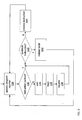
- FIG. 3 is a flow-chart illustrating instruction processing performed by a network processor engine.
- FIG. 4 is a flow-diagram illustrating caching of instructions.
- FIG. 6 is a map of instruction cache memory allocated to different threads of a network processor engine.
- FIG. 7 is a diagram of a network processor engine.
- FIG. 8 is a diagram of a network processor.
- FIG. 9 is a diagram of a network device.
- each engine 102 includes an instruction cache 104 that stores a subset of program 108 instructions.
- instruction cache 104a of packet engine 102a holds segment 108b of program 108.
- the remainder of the program 108 is stored in an instruction store 106 shared by the engines 102.
- the engine 102a may need to access a program segment other than segment 108b.
- the program may branch or sequentially advance to a point within the program 108 outside segment 108b.
- the network processor 100 will download requested/needed segment(s) to the engine's 102a cache 104a.
- the segment(s) stored by the cache dynamically change as program execution proceeds.
- multiple engines 102 receive instructions to cache from instruction store 106.
- the shared instruction store 106 may, in turn, cache instructions from a hierarchically higher instruction store 110 internal or external to the processor 100.
- instructions stores 104, 106, and 110 may form a cache hierarchy that include an L1 instruction cache 104 of the engine and an L2 instruction cache 106 shared by different engines.
- FIG. 1 depicts the instruction store 106 as serving all engines 102
- a network processor 100 may instead feature multiple shared stores 106 that serve different sets of engines 102.
- one shared instruction store 106 may store program instructions for engines #1 to #4 while another stores program instructions for engines #5 to #8.
- FIG. 1 depicted the engine cache 104 and instruction store 106 as storing instructions of a single program 108, they may instead store sets of instructions belonging to different programs.
- a shared instruction store 106 may store different program instructions for each engine 102 or even different engine 102 threads.
- FIG. 1 depicts instructions 108 as source code to ease illustration.
- the actual instructions stored by the shared store 106 and distributed by to the engines would typically be executable instructions expressed in the instruction set provided by the engines.
- FIG 2 depicts a portion of a program source code listing that includes a fetch instruction 122 that allows the program to initiate a "prefetch" of program instructions into the engine's cache 104 ahead of the time when the instructions will be required to continue execution of a program.
- the fetch instruction 122 causes the engine 102n to issue ("1") a request to the shared instruction store 106 for the next needed segment 108b before execution advances to a point within the next segment 108b.
- the engine 102 continues processing instructions 124 following the fetch instruction 122, the requested segment 108b is loaded into the engine's 102n instruction cache 104n.
- the time used to retrieve ("2") a program segment overlaps the time between engine execution of the pre-fetch instruction 122 and the time the engine 102 "runs out” of instructions to execute in the currently cached program segment(s).
- the time to retrieve program instructions was concealed by the time spent executing instructions 122 following the fetch instruction.
- the fetch delay may also be "hidden” by executing the fetch instruction after instructions 120 (e.g., memory operations) that take some time to complete.
- the sample fetch instruction shown in FIG. 2 has a syntax of:
- the SegmentAddress identifies the starting address of the program to retrieve from the shared store 106 and the SegmentCount identifies the number of subsequent segments to fetch. Potentially, the SegmentAddress may be restricted to identify the starting address of program segments.
- the optional_token has a syntax of:
- the instruction syntax shown in FIG. 2 is merely an example and other instructions to fetch program instructions may feature different parameters, keywords, and feature different options. Additionally, the instruction may exist at different levels. For example, the instruction may be part of the instruction set of an engine. Alternately, the instruction may be a source code instruction processed by a compiler to generate target instructions (e.g., engine executable instructions) corresponding to the fetch instruction. Such a compiler may perform other traditional compiler operations such as lexical analysis to group text characters of source code into "tokens", syntax analysis that groups the tokens into grammatical phrases, intermediate code generation that more abstractly represents the source code, optimization, and so forth.
- a compiler may perform other traditional compiler operations such as lexical analysis to group text characters of source code into "tokens", syntax analysis that groups the tokens into grammatical phrases, intermediate code generation that more abstractly represents the source code, optimization, and so forth.
- a fetch instruction may be manually inserted by a programmer during code development. For example, based on initial classification of a packet, the remaining program flow for the packet may be known. Thus, fetch instructions may retrieve the segments needed to process a packet after the classification.
- a program written in a high-level language may include instructions of:
- the fetch instruction may also be inserted into code by a software development tool such as a compiler, analyzer, profiler, and/or pre-processor.
- a software development tool such as a compiler, analyzer, profiler, and/or pre-processor.
- code flow analysis may identify when different program segments should be loaded.
- the compiler may insert the fetch instruction after a memory access instruction or before a set of instructions that take some time to execute.
- FIG. 3 depicts a flow-chart illustrating operation of an engine that retrieves instructions both "on-demand” and in response to "fetch” instructions.
- a program counter 130 identifying the next program instruction to execute is updated. For example, the program counter 130 may be incremented to advance to a next sequential instruction address or the counter 130 may be set to some other instruction address in response to a branch instruction.
- an engine determines 132 whether the engine's instruction cache currently holds the instruction identified by the program counter. If not, the engine thread stalls 134 (e.g., the thread requiring the instruction is swapped out of the engine) until 138 a fetch 136 retrieves the missing instruction from the shared store.
- FIG. 4 depicts a sample architecture of a shared instruction cache 106.
- the instruction cache 106 receives instructions ("1") to share with the engines, for example, during network processor startup. Thereafter, the shared instruction cache 106 distributes portions of the instructions 108 to the engines as needed and/or requested.
- Bus 150 carries ("2") fetch requests to the shared cache 106. These requests can identify the program segment(s) 108 to fetch and the engine making the request. The requests may also identify whether the request is a pre-fetch or an "on-demand" fetch.
- a high-bandwidth bus 152 carries ("4") instructions in the requested program segment(s) back to the requesting engine 102. The bandwidth of bus 152 may permit the shared cache 106 to deliver requested instructions to multiple engines simultaneously.
- the bus 152 may be divided into n-lines that can be dynamically allocated to the engines. For example, if four engines request segments, each can be allocated 25% of the bus bandwidth.
- FIG. 5 illustrates a sample architecture of an engine's instruction cache.
- cache storage is provided by a collection of memory devices 166x that store instructions received from the shared instruction store 106 over bus 164.
- An individual memory element 166a may be sized to hold one program segment.
- each memory 166x is associated with an address decoder that receives the address of an instruction to be processed from the engine and determines whether the instruction is present within the associated memory 166.
- the different decoders operate on an address in parallel. That is, each decoder searches its associated memory at the same time. If found within one of the memories 166x, that memory 166x unit outputs 168 the requested instruction for processing by the engine. If the instruction address is not found in any of the memories 166, a "miss" signal 168 is generated.
- FIG. 6 depicts a memory map of an engine's instruction cache 104 where each engine thread is exclusively allocated a portion of the cache 104.
- thread 0 172 is allocated memory for N program segments 172a, 172b, 172n.
- Instruction segments fetched for a thread can reside in the thread's allocation of the cache 104.
- logic may restrict one thread from victimizing segments from cache partitions allocated to other threads.
- a memory allocation scheme such as the scheme depicted in FIG. 6 can prevent inter-thread thrashing.
- an access count may be associated with the threads currently using a segment. When the count reaches zero, the segment may be victimized.
- a cache victimization scheme may apply different rules. For example, the scheme may try to avoid victimizing a loaded segment which has not yet been accessed by any thread.
- FIG. 7 illustrates a sample engine 102 architecture.
- the engine 102 may be a Reduced Instruction Set Computing (RISC) processor tailored for packet processing.
- RISC Reduced Instruction Set Computing
- the engines 102 may not provide floating point or integer division instructions commonly provided by the instruction sets of general purpose processors.
- the sample engine 102 shown provides multiple threads of execution.
- the engine 102 stores a program context 182 for each thread.
- This context 182 can include thread state data such as a program counter.
- a thread arbiter 182 selects the program context 182x of a thread to execute.
- the program counter for the selected context is fed to an instruction cache 104.
- the cache 104 can initiate a program segment fetch when the instruction identified by the program counter is not currently cached (e.g., the segment is not in the lock-down cache region or the region allocated to the currently executing thread). Otherwise, the cache 104 can send the cached instruction to the instruction decode unit 186.
- the instruction decode unit 190 may identify the instruction as a "fetch" instruction and may initiate a segment fetch. Otherwise the decode 190 unit may feed the instruction to an execution unit (e.g., an ALU) for processing or may initiate a request to a resource shared by different engines (e.g., a memory controller) via command queue 188.
- a fetch control unit 184 handles retrieval of program segments from the shared cache 106. For example, the fetch control unit 184 can negotiate for access to the shared cache request bus, issue a request, and store the returned instructions in the instruction cache 104. The fetch control unit 184 may also handle victimization of previously cached instructions.
- FIG. 8 depicts an example of network processor 200.
- the network processor 200 shown is an Intel® Internet eXchange network Processor (IXP). Other network processors feature different designs.
- IXP Internet eXchange network Processor
- the network processor 200 shown features a collection of packet engines 204 integrated on a single die. As described above, an individual packet engine 204 may offer multiple threads.
- the processor 200 may also include a core processor 210 (e.g., a StrongARM® XScale®) that is often programmed to perform "control plane” tasks involved in network operations.
- the core processor 210 may also handle "data plane” tasks and may provide additional packet processing threads.
- the network processor 200 also features interfaces 202 that can carry packets between the processor 200 and other network components.
- the processor 200 can feature a switch fabric interface 202 (e.g., a Common Switch Interface (CSIX) interface) that enables the processor 200 to transmit a packet to other processor(s) or circuitry connected to the fabric.
- the processor 200 can also feature an interface 202 (e.g., a System Packet Interface (SPI) interface) that enables to the processor 200 to communicate with physical layer (PHY) and/or link layer devices.
- the processor 200 also includes an interface 208 (e.g., a Peripheral Component Interconnect (PCI) bus interface) for communicating, for example, with a host.
- the processor 200 also includes other components shared by the engines such as memory controllers 206, 212, a hash engine, and scratch pad memory.
- the packet processing techniques described above may be implemented on a network processor, such as the IXP, in a wide variety of ways.
- the core processor 210 may deliver program instructions to the shared instruction cache 106 during network processor bootup.
- the processor 200 may feature an N-deep instruction cache hierarchy, for example, when the processor features a very large number of engines
- FIG. 9 depicts a network device incorporating techniques described above.
- the device features a collection of line cards 300 ("blades") interconnected by a switch fabric 310 (e.g., a crossbar or shared memory switch fabric).
- the switch fabric for example, may conform to CSIX or other fabric technologies such as HyperTransport, Infiniband, Peripheral Component Interconnect - Express (PCI-X), and so forth.
- PCI-X Peripheral Component Interconnect - Express
- Individual line cards may include one or more physical layer (PHY) devices 302 (e.g., optic, wire, and wireless PHYs) that handle communication over network connections.
- PHY physical layer
- the PHYs translate between the physical signals carried by different network mediums and the bits (e.g., "0"-s and "1"-s) used by digital systems.
- the line cards 300 may also include framer devices (e.g., Ethernet, Synchronous Optic Network (SONET), High-Level Data Link (HDLC) framers or other "layer 2" devices) 304 that can perform operations on frames such as error detection and/or correction.
- the line cards 300 shown also include one or more network processors 306 using instruction caching techniques described above.
- the network processors 306 are programmed to perform packet processing operations for packets received via the PHY(s) 300 and direct the packets, via the switch fabric 310, to a line card providing the selected egress interface. Potentially, the network processor(s) 306 may perform "layer 2" duties instead of the framer devices 304.
- FIGs. 8 and 9 described sample architectures of an engine, network processor, and a device incorporating network processors, the techniques may be implemented in other engine, network processor, and device designs. Additionally, the techniques may be used in a wide variety of network devices (e.g., a router, switch, bridge, hub, traffic generator, and so forth).
- network devices e.g., a router, switch, bridge, hub, traffic generator, and so forth.
- circuitry as used herein includes hardwired circuitry, digital circuitry, analog circuitry, programmable circuitry, and so forth.
- the programmable circuitry may operate on computer programs.
Landscapes
- Engineering & Computer Science (AREA)
- Theoretical Computer Science (AREA)
- Software Systems (AREA)
- Physics & Mathematics (AREA)
- General Engineering & Computer Science (AREA)
- General Physics & Mathematics (AREA)
- Multimedia (AREA)
- Computer Networks & Wireless Communication (AREA)
- Signal Processing (AREA)
- Memory System Of A Hierarchy Structure (AREA)
- Small-Scale Networks (AREA)
- Executing Machine-Instructions (AREA)
- Microcomputers (AREA)
Abstract
Description
- This is an application relates to the following applications filed on the same day as the present application:
- a. Attorney Docket No. P16851 - "SERVICING ENGINE CACHE REQUESTS";
- b. Attorney Docket No. P16852 - "THREAD-BASED ENGINE CACHE PARTITIONING"
- Networks enable computers and other devices to communicate. For example, networks can carry data representing video, audio, e-mail, and so forth. Typically, data sent across a network is divided into smaller messages known as packets. By analogy, a packet is much like an envelope you drop in a mailbox. A packet typically includes "payload" and a "header". The packet's "payload" is analogous to the letter inside the envelope. The packet's "header" is much like the information written on the envelope itself. The header can include information to help network devices handle the packet appropriately. For example, the header can include an address that identifies the packet's destination.
- A given packet may "hop" across many different intermediate network devices (e.g., "routers", "bridges" and "switches") before reaching its destination. These intermediate devices often perform a variety of packet processing operations. For example, intermediate devices often perform operations to determine how to forward a packet further toward its destination or determine a quality of service to use in handling the packet.
- As network connection speeds increase, the amount of time an intermediate device has to process a packet continues to dwindle. To achieve fast packet processing, many devices feature dedicated, "hard-wired" designs such as Application Specific Integrated Circuits (ASICs). These designs, however, are often difficult to adapt to emerging networking technologies and communication protocols.
- To combine flexibility with the speed often associated with an ASIC, some network devices feature programmable network processors. Network processors enable software engineers to quickly reprogram network processor operations.
- Often, again due to the increasing speed of network connections, the time it takes to process a packet greatly exceeds the rate at which the packets arrive. Thus, the architecture of some network processors features multiple processing engines that process packets simultaneously. For example, while one engine determines how to forward one packet, another engine determines how to forward a different one. While the time to process a given packet may remain the same, processing multiple packets at the same time enables the network processor to keep apace the deluge of arriving packets.
-
US 6 574 712 B1 discloses a software prefetch system and method for predetermining amount of streamed data wherein prefetch requests are dynamically determined and issued by aprefetch engine 202 in response to analysis of previous accesses. - The invention is as set out in
independent claims 1 and 7. -
FIG. 1 is a diagram illustrating instruction caches of a network processor. -
FIG. 2 is a diagram illustrating operation of an instruction to fetch instructions into an engine's instruction cache. -
FIG. 3 is a flow-chart illustrating instruction processing performed by a network processor engine. -
FIG. 4 is a flow-diagram illustrating caching of instructions. -
FIG. 5 is a diagram illustrating engine circuitry to search for cached instructions. -
FIG. 6 is a map of instruction cache memory allocated to different threads of a network processor engine. -
FIG. 7 is a diagram of a network processor engine. -
FIG. 8 is a diagram of a network processor. -
FIG. 9 is a diagram of a network device. -
FIG. 1 depicts anetwork processor 100 that includesmultiple processing engines 102. Theengines 102 can be programmed to perform a wide variety of packet processing operations such as determining a packet's next hop, applying Quality of Service (QoS), metering packet traffic, and so forth. In the architecture shown, theengines 102 executeprogram instructions 108 stored in a high-speedlocal memory 104 of theengine 102. Due to size and cost constraints, the amount ofinstruction memory 104 provided by anengine 102 is often limited. To prevent the limited storage ofengine memory 104 from imposing too stiff a restriction on the overall size and complexity of aprogram 108,FIG. 1 illustrates an example of an instruction caching scheme that dynamically downloads segments (e.g., 108b) of alarger program 108 to anengine 102 as the engine's 102 execution of theprogram 108 proceeds. - In the example shown in
FIG. 1 , eachengine 102 includes aninstruction cache 104 that stores a subset ofprogram 108 instructions. For example,instruction cache 104a ofpacket engine 102a holdssegment 108b ofprogram 108. The remainder of theprogram 108 is stored in aninstruction store 106 shared by theengines 102. - Eventually, the
engine 102a may need to access a program segment other thansegment 108b. For example, the program may branch or sequentially advance to a point within theprogram 108outside segment 108b. To permit theengine 102 to continueprogram 108 execution, thenetwork processor 100 will download requested/needed segment(s) to the engine's102a cache 104a. Thus, the segment(s) stored by the cache dynamically change as program execution proceeds. - As shown in
FIG. 1 ,multiple engines 102 receive instructions to cache frominstruction store 106. The sharedinstruction store 106 may, in turn, cache instructions from a hierarchicallyhigher instruction store 110 internal or external to theprocessor 100. In other words, instructions stores 104, 106, and 110 may form a cache hierarchy that include anL1 instruction cache 104 of the engine and anL2 instruction cache 106 shared by different engines. - While
FIG. 1 depicts theinstruction store 106 as serving allengines 102, anetwork processor 100 may instead feature multiple sharedstores 106 that serve different sets ofengines 102. For example, one sharedinstruction store 106 may store program instructions forengines # 1 to #4 while another stores program instructions for engines #5 to #8. Additionally, whileFIG. 1 depicted theengine cache 104 andinstruction store 106 as storing instructions of asingle program 108, they may instead store sets of instructions belonging to different programs. For instance, a sharedinstruction store 106 may store different program instructions for eachengine 102 or evendifferent engine 102 threads. -
FIG. 1 depictsinstructions 108 as source code to ease illustration. The actual instructions stored by the sharedstore 106 and distributed by to the engines would typically be executable instructions expressed in the instruction set provided by the engines. - Potentially, a program segment needed by an
engine 102 to continue program execution may be provided on an "on-demand" basis. That is, theengine 102 may continue to executeinstructions 108b stored in theinstruction cache 104a until an instruction requiring execution is not found in thecache 104a. When this occurs, theengine 102 may signal the sharedstore 106 to deliver the program segment including the next instruction to be executed. This "on-demand" scenario, however, can introduce a delay intoengine 102 execution of a program. That is, in the "on-demand" sequence, an engine 102 (orengine 102 thread) may sit idle until the needed instruction is loaded. This delay may be caused not only by the operations involved in downloading the needed instructions to theengine 102L1 cache 104, but also by competition among theengines 102b-102n for access to the sharedstore 106. - To, potentially, avoid this delay,
FIG 2 depicts a portion of a program source code listing that includes a fetchinstruction 122 that allows the program to initiate a "prefetch" of program instructions into the engine'scache 104 ahead of the time when the instructions will be required to continue execution of a program. For example, as shown inFIG. 2 , the fetchinstruction 122 causes theengine 102n to issue ("1") a request to the sharedinstruction store 106 for the next neededsegment 108b before execution advances to a point within thenext segment 108b. While theengine 102 continues processinginstructions 124 following the fetchinstruction 122, the requestedsegment 108b is loaded into the engine's102n instruction cache 104n. In other words, the time used to retrieve ("2") a program segment overlaps the time between engine execution of thepre-fetch instruction 122 and the time theengine 102 "runs out" of instructions to execute in the currently cached program segment(s). - In the example shown in
FIG. 2 , the time to retrieve program instructions was concealed by the time spent executinginstructions 122 following the fetch instruction. The fetch delay may also be "hidden" by executing the fetch instruction after instructions 120 (e.g., memory operations) that take some time to complete. - The sample fetch instruction shown in
FIG. 2 has a syntax of: - Prefetch (SegmentAddress,SegmentCount)[, optional_token]
- where the SegmentAddress identifies the starting address of the program to retrieve from the shared
store 106 and the SegmentCount identifies the number of subsequent segments to fetch. Potentially, the SegmentAddress may be restricted to identify the starting address of program segments. - The optional_token has a syntax of:
- optional_token = [ctx_swap[signal],][sig_done[signal]]
- The ctx_swap parameter instructs an
engine 102 to swap to another engine thread of execution until a signal indicates completion of the program segment fetch. The sig_done parameter also identifies a status signal to be set upon completion of the fetch, but does not instruct theengine 102 to swap contexts. - The instruction syntax shown in
FIG. 2 is merely an example and other instructions to fetch program instructions may feature different parameters, keywords, and feature different options. Additionally, the instruction may exist at different levels. For example, the instruction may be part of the instruction set of an engine. Alternately, the instruction may be a source code instruction processed by a compiler to generate target instructions (e.g., engine executable instructions) corresponding to the fetch instruction. Such a compiler may perform other traditional compiler operations such as lexical analysis to group text characters of source code into "tokens", syntax analysis that groups the tokens into grammatical phrases, intermediate code generation that more abstractly represents the source code, optimization, and so forth. - A fetch instruction may be manually inserted by a programmer during code development. For example, based on initial classification of a packet, the remaining program flow for the packet may be known. Thus, fetch instructions may retrieve the segments needed to process a packet after the classification. For example, a program written in a high-level language may include instructions of:
-
 switch(classify(packet.header)) {
           case DropPacket: {
             prefetch(DropCounterInstructions);
          }
          case ForwardPacket {
             prefetch(RoutingLookupInstructions)
             prefetch(PacketEnqueueInstructions);
           }}
Claims (12)
- A processor (100), comprising:an instruction store (106) to store instructions of at least a portion of at least one program (108);a set of multiple engines (102a-102n) coupled to the instruction store (106), individual ones of the engines (102a-102n) including an engine instruction cache (104a-104n) and circuitry to request a subset of the at least the portion of the at least one program (108; andthe circuitry comprises circuitry to issue a demand request for program instructions (108) when an instruction requiring execution is not found in the engine instruction cache (104a-104n) and to issue a fetch request for program instructions (108) in response to a fetch instruction included in the program instructions; characterized in thatthe instruction store (106) comprises a first FIFO queue to enqueue fetch requests, a demand FIFO queue to enqueue demand requests, and an arbiter (156) that prioritizes servicing of the demand FIFO ahead of the first FIFO.
- The processor (100) of claim 1, wherein
the engine instruction cache (104a-104n) comprises an L1 cache; and
the instruction store (106) comprises an L2 cache. - The processor (100) of claim 1, wherein the engines (102a-102n) each comprise multi- threaded engines and wherein each engine instruction cache (104a-104n) comprises a respective portion (172-174) exclusively allocated to each engine (102a-102n) thread and portion (170) shared by all threads of an engine (102a-102n) that is protected for victimization.
- The processor (1001) of claim 1, wherein the engine (102a-102n) comprises circuitry to select instructions to victimize from the engine instruction cache (104a-104n).
- The processor (100) of claim 1, further comprising at least one of the following: an interface to a switch fabric, an interface to a media access controller (MAC), and an interface to a physical layer (PHY) device.
- The processor of claim 1,
wherein a bus (152) couples each of the multiple engines (104a-104n) to the instruction store (106), wherein the bus (152) comprises multiple lines, wherein the bus delivers requested instructions to multiple engines (104a-104n) simultaneously, and wherein the bus (152) lines are dynamically allocated to the engines (104a-104n); and
wherein the number of lines allocated to the engines is changed to increase the number of lines allocated to an engine that issues a fetch request in response to a cache miss. - A method comprising:requesting a subset of instructions (108) stored by an instruction store shared by multiple engines (102a-102n) integrated on a single die;receiving the subset of instructions (108) at a one of the multiple engines (102a-102n) requesting the subset;storing the received subset of instructions (108) in an instruction cache (104a-104n) of the one of the multiple engines (102a-102n); andeach instruction cache (104a-104n) of the multiple engines (102a-102n) comprises circuitry to issue a demand request for program instructions (108) when an instruction requiring execution is not found in the engine instruction cache (104a-104n) and to issue a fetch request for program instructions (108) in response to a fetch instruction included in the program instructions; characterized in thatthe instruction store (106) comprises a first FIFO queue to enqueue fetch requests, a demand FIFO queue and enqueue demand requests, and an arbiter (156) that prioritizes servicing of the demand FIFO ahead of the first FIFO.
- The method of claim 7, wherein the instruction store (106) comprises an L2 cache; and
wherein the instruction cache (104a-104n) of the one of the multiple engines (102a-102n) comprises an L1 cache. - The method of claim 7, wherein each of the engines (102a-102n) comprise multi- threaded engines and wherein each engine instruction cache (104a-104n) comprises a respective portion (172-174) exclusively allocated to each engine (102a-102n) thread and a portion (170) shared by all threads of an engine (102a-102n) that is protected for victimization.
- The method of claim 7, further comprising selecting instructions to victimize from the engine instruction cache (104a-104n).
- The method of claim 10, further comprising executing the subset of instructions (108) to process a packet received over a network.
- A network forwarding device, comprising:a switch fabric (310);a set of line cards (300a-300n) interconnected by the switch fabric (310), at least one of the set of line cards (300a-300n) comprising:at least one PHY (302); andat least one network processor (306) in accordance with claim 1.
Applications Claiming Priority (2)
| Application Number | Priority Date | Filing Date | Title |
|---|---|---|---|
| US10/704,432 US20050102474A1 (en) | 2003-11-06 | 2003-11-06 | Dynamically caching engine instructions |
| PCT/US2004/035923 WO2005048113A2 (en) | 2003-11-06 | 2004-10-29 | Dynamically caching engine instructions for on demand program execution |
Publications (2)
| Publication Number | Publication Date |
|---|---|
| EP1680743A2 EP1680743A2 (en) | 2006-07-19 |
| EP1680743B1 true EP1680743B1 (en) | 2010-10-06 |
Family
ID=34552126
Family Applications (1)
| Application Number | Title | Priority Date | Filing Date |
|---|---|---|---|
| EP04796714A Expired - Lifetime EP1680743B1 (en) | 2003-11-06 | 2004-10-29 | Dynamically caching engine instructions for on demand program execution |
Country Status (7)
| Country | Link |
|---|---|
| US (1) | US20050102474A1 (en) |
| EP (1) | EP1680743B1 (en) |
| JP (1) | JP2007510989A (en) |
| CN (1) | CN1997973B (en) |
| AT (1) | ATE484027T1 (en) |
| DE (1) | DE602004029485D1 (en) |
| WO (1) | WO2005048113A2 (en) |
Families Citing this family (15)
| Publication number | Priority date | Publication date | Assignee | Title |
|---|---|---|---|---|
| US7376789B2 (en) * | 2005-06-29 | 2008-05-20 | Intel Corporation | Wide-port context cache apparatus, systems, and methods |
| US20070005898A1 (en) * | 2005-06-30 | 2007-01-04 | William Halleck | Method, apparatus and system for task context cache replacement |
| US7676604B2 (en) * | 2005-11-22 | 2010-03-09 | Intel Corporation | Task context direct indexing in a protocol engine |
| US8166277B2 (en) * | 2008-02-01 | 2012-04-24 | International Business Machines Corporation | Data prefetching using indirect addressing |
| US8209488B2 (en) * | 2008-02-01 | 2012-06-26 | International Business Machines Corporation | Techniques for prediction-based indirect data prefetching |
| CN102571761B (en) * | 2011-12-21 | 2014-08-20 | 四川长虹电器股份有限公司 | Information transmission method of network interface |
| US10095847B2 (en) * | 2012-05-25 | 2018-10-09 | Koninklijke Philips N.V. | Method, system and device for protection against reverse engineering and/or tampering with programs |
| CN102855213B (en) * | 2012-07-06 | 2017-10-27 | 中兴通讯股份有限公司 | A kind of instruction storage method of network processing unit instruction storage device and the device |
| US9223705B2 (en) * | 2013-04-01 | 2015-12-29 | Advanced Micro Devices, Inc. | Cache access arbitration for prefetch requests |
| US9286258B2 (en) | 2013-06-14 | 2016-03-15 | National Instruments Corporation | Opaque bridge for peripheral component interconnect express bus systems |
| US11397520B2 (en) | 2013-08-01 | 2022-07-26 | Yogesh Chunilal Rathod | Application program interface or page processing method and device |
| WO2015015251A1 (en) * | 2013-08-01 | 2015-02-05 | Yogesh Chunilal Rathod | Presenting plurality types of interfaces and functions for conducting various activities |
| CN113326020B (en) | 2020-02-28 | 2025-04-25 | 昆仑芯(北京)科技有限公司 | Cache device, cache, system, data processing method, device and medium |
| WO2022088074A1 (en) * | 2020-10-30 | 2022-05-05 | 华为技术有限公司 | Instruction processing method based on multiple instruction engines, and processor |
| CN116151338A (en) * | 2021-11-19 | 2023-05-23 | 平头哥(上海)半导体技术有限公司 | Cache access method and correlative graph neural network system |
Family Cites Families (22)
| Publication number | Priority date | Publication date | Assignee | Title |
|---|---|---|---|---|
| JPS60263238A (en) * | 1984-06-11 | 1985-12-26 | Nippon Telegr & Teleph Corp <Ntt> | Information processor |
| JPH03268041A (en) * | 1990-03-17 | 1991-11-28 | Res Dev Corp Of Japan | Cache operation clarifying computer |
| US6021471A (en) * | 1994-11-15 | 2000-02-01 | Advanced Micro Devices, Inc. | Multiple level cache control system with address and data pipelines |
| JPH096633A (en) * | 1995-06-07 | 1997-01-10 | Internatl Business Mach Corp <Ibm> | Method and system for operation of high-performance multiplelogical route in data-processing system |
| JPH09282223A (en) * | 1996-04-12 | 1997-10-31 | Ricoh Co Ltd | Memory controller |
| US6446143B1 (en) * | 1998-11-25 | 2002-09-03 | Compaq Information Technologies Group, L.P. | Methods and apparatus for minimizing the impact of excessive instruction retrieval |
| JP3420091B2 (en) * | 1998-11-30 | 2003-06-23 | Necエレクトロニクス株式会社 | Microprocessor |
| US6393551B1 (en) * | 1999-05-26 | 2002-05-21 | Infineon Technologies North America Corp. | Reducing instruction transactions in a microprocessor |
| US6985431B1 (en) * | 1999-08-27 | 2006-01-10 | International Business Machines Corporation | Network switch and components and method of operation |
| US6668317B1 (en) * | 1999-08-31 | 2003-12-23 | Intel Corporation | Microengine for parallel processor architecture |
| US6606704B1 (en) * | 1999-08-31 | 2003-08-12 | Intel Corporation | Parallel multithreaded processor with plural microengines executing multiple threads each microengine having loadable microcode |
| JP3741945B2 (en) * | 1999-09-30 | 2006-02-01 | 富士通株式会社 | Instruction fetch control device |
| US6574712B1 (en) * | 1999-11-08 | 2003-06-03 | International Business Machines Corporation | Software prefetch system and method for predetermining amount of streamed data |
| US6470427B1 (en) * | 1999-11-09 | 2002-10-22 | International Business Machines Corporation | Programmable agent and method for managing prefetch queues |
| JP2001236221A (en) * | 2000-02-21 | 2001-08-31 | Keisuke Shindo | Pipe line parallel processor using multi-thread |
| JP2001344153A (en) * | 2000-05-30 | 2001-12-14 | Nec Corp | Cash memory controller for multiprocessor system |
| JP2002132702A (en) * | 2000-10-30 | 2002-05-10 | Nec Eng Ltd | Memory control system |
| US20020181476A1 (en) * | 2001-03-17 | 2002-12-05 | Badamo Michael J. | Network infrastructure device for data traffic to and from mobile units |
| US7487505B2 (en) * | 2001-08-27 | 2009-02-03 | Intel Corporation | Multithreaded microprocessor with register allocation based on number of active threads |
| US7120755B2 (en) * | 2002-01-02 | 2006-10-10 | Intel Corporation | Transfer of cache lines on-chip between processing cores in a multi-core system |
| US6915415B2 (en) * | 2002-01-07 | 2005-07-05 | International Business Machines Corporation | Method and apparatus for mapping software prefetch instructions to hardware prefetch logic |
| US20050050306A1 (en) * | 2003-08-26 | 2005-03-03 | Sridhar Lakshmanamurthy | Executing instructions on a processor |
-
2003
- 2003-11-06 US US10/704,432 patent/US20050102474A1/en not_active Abandoned
-
2004
- 2004-10-29 AT AT04796714T patent/ATE484027T1/en not_active IP Right Cessation
- 2004-10-29 JP JP2006538286A patent/JP2007510989A/en active Pending
- 2004-10-29 EP EP04796714A patent/EP1680743B1/en not_active Expired - Lifetime
- 2004-10-29 DE DE602004029485T patent/DE602004029485D1/en not_active Expired - Lifetime
- 2004-10-29 CN CN200480040023XA patent/CN1997973B/en not_active Expired - Fee Related
- 2004-10-29 WO PCT/US2004/035923 patent/WO2005048113A2/en not_active Ceased
Also Published As
| Publication number | Publication date |
|---|---|
| EP1680743A2 (en) | 2006-07-19 |
| US20050102474A1 (en) | 2005-05-12 |
| JP2007510989A (en) | 2007-04-26 |
| WO2005048113A2 (en) | 2005-05-26 |
| WO2005048113A3 (en) | 2006-11-23 |
| ATE484027T1 (en) | 2010-10-15 |
| DE602004029485D1 (en) | 2010-11-18 |
| CN1997973A (en) | 2007-07-11 |
| CN1997973B (en) | 2010-06-09 |
Similar Documents
| Publication | Publication Date | Title |
|---|---|---|
| US8087024B2 (en) | Multiple multi-threaded processors having an L1 instruction cache and a shared L2 instruction cache | |
| CN100378655C (en) | Multi-threaded execution in parallel processors | |
| CA2388740C (en) | Sdram controller for parallel processor architecture | |
| Adiletta et al. | The Next Generation of Intel IXP Network Processors. | |
| CA2456837C (en) | Mechanism for providing early coherency detection to enable high performance memory updates in a latency sensitive multithreaded environment | |
| EP1586037B1 (en) | A software controlled content addressable memory in a general purpose execution datapath | |
| CA2391792C (en) | Sram controller for parallel processor architecture | |
| US7000048B2 (en) | Apparatus and method for parallel processing of network data on a single processing thread | |
| EP1236094B1 (en) | Branch instruction for multithreaded processor | |
| US20140201402A1 (en) | Context Switching with Offload Processors | |
| US7240164B2 (en) | Folding for a multi-threaded network processor | |
| US20030115347A1 (en) | Control mechanisms for enqueue and dequeue operations in a pipelined network processor | |
| US20050102474A1 (en) | Dynamically caching engine instructions | |
| US7467256B2 (en) | Processor having content addressable memory for block-based queue structures | |
| US20040093602A1 (en) | Method and apparatus for serialized mutual exclusion | |
| US20060179277A1 (en) | System and method for instruction line buffer holding a branch target buffer | |
| US7325099B2 (en) | Method and apparatus to enable DRAM to support low-latency access via vertical caching | |
| US7418543B2 (en) | Processor having content addressable memory with command ordering | |
| US7277990B2 (en) | Method and apparatus providing efficient queue descriptor memory access | |
| US20050108479A1 (en) | Servicing engine cache requests | |
| US20060067348A1 (en) | System and method for efficient memory access of queue control data structures |
Legal Events
| Date | Code | Title | Description |
|---|---|---|---|
| PUAI | Public reference made under article 153(3) epc to a published international application that has entered the european phase |
Free format text: ORIGINAL CODE: 0009012 |
|
| 17P | Request for examination filed |
Effective date: 20060510 |
|
| AK | Designated contracting states |
Kind code of ref document: A2 Designated state(s): AT BE BG CH CY CZ DE DK EE ES FI FR GB GR HU IE IT LI LU MC NL PL PT RO SE SI SK TR |
|
| AX | Request for extension of the european patent |
Extension state: AL HR LT LV MK |
|
| PUAK | Availability of information related to the publication of the international search report |
Free format text: ORIGINAL CODE: 0009015 |
|
| DAX | Request for extension of the european patent (deleted) | ||
| 17Q | First examination report despatched |
Effective date: 20071214 |
|
| GRAP | Despatch of communication of intention to grant a patent |
Free format text: ORIGINAL CODE: EPIDOSNIGR1 |
|
| GRAS | Grant fee paid |
Free format text: ORIGINAL CODE: EPIDOSNIGR3 |
|
| GRAA | (expected) grant |
Free format text: ORIGINAL CODE: 0009210 |
|
| AK | Designated contracting states |
Kind code of ref document: B1 Designated state(s): AT BE BG CH CY CZ DE DK EE ES FI FR GB GR HU IE IT LI LU MC NL PL PT RO SE SI SK TR |
|
| REG | Reference to a national code |
Ref country code: GB Ref legal event code: FG4D |
|
| REG | Reference to a national code |
Ref country code: CH Ref legal event code: EP |
|
| REG | Reference to a national code |
Ref country code: IE Ref legal event code: FG4D |
|
| REF | Corresponds to: |
Ref document number: 602004029485 Country of ref document: DE Date of ref document: 20101118 Kind code of ref document: P |
|
| REG | Reference to a national code |
Ref country code: NL Ref legal event code: VDEP Effective date: 20101006 |
|
| PG25 | Lapsed in a contracting state [announced via postgrant information from national office to epo] |
Ref country code: SI Free format text: LAPSE BECAUSE OF FAILURE TO SUBMIT A TRANSLATION OF THE DESCRIPTION OR TO PAY THE FEE WITHIN THE PRESCRIBED TIME-LIMIT Effective date: 20101006 |
|
| PGFP | Annual fee paid to national office [announced via postgrant information from national office to epo] |
Ref country code: DE Payment date: 20101027 Year of fee payment: 7 |
|
| PG25 | Lapsed in a contracting state [announced via postgrant information from national office to epo] |
Ref country code: FI Free format text: LAPSE BECAUSE OF FAILURE TO SUBMIT A TRANSLATION OF THE DESCRIPTION OR TO PAY THE FEE WITHIN THE PRESCRIBED TIME-LIMIT Effective date: 20101006 Ref country code: AT Free format text: LAPSE BECAUSE OF FAILURE TO SUBMIT A TRANSLATION OF THE DESCRIPTION OR TO PAY THE FEE WITHIN THE PRESCRIBED TIME-LIMIT Effective date: 20101006 Ref country code: PT Free format text: LAPSE BECAUSE OF FAILURE TO SUBMIT A TRANSLATION OF THE DESCRIPTION OR TO PAY THE FEE WITHIN THE PRESCRIBED TIME-LIMIT Effective date: 20110207 Ref country code: SE Free format text: LAPSE BECAUSE OF FAILURE TO SUBMIT A TRANSLATION OF THE DESCRIPTION OR TO PAY THE FEE WITHIN THE PRESCRIBED TIME-LIMIT Effective date: 20101006 Ref country code: BG Free format text: LAPSE BECAUSE OF FAILURE TO SUBMIT A TRANSLATION OF THE DESCRIPTION OR TO PAY THE FEE WITHIN THE PRESCRIBED TIME-LIMIT Effective date: 20110106 Ref country code: MC Free format text: LAPSE BECAUSE OF NON-PAYMENT OF DUE FEES Effective date: 20101031 Ref country code: NL Free format text: LAPSE BECAUSE OF FAILURE TO SUBMIT A TRANSLATION OF THE DESCRIPTION OR TO PAY THE FEE WITHIN THE PRESCRIBED TIME-LIMIT Effective date: 20101006 |
|
| REG | Reference to a national code |
Ref country code: CH Ref legal event code: PL |
|
| PG25 | Lapsed in a contracting state [announced via postgrant information from national office to epo] |
Ref country code: GR Free format text: LAPSE BECAUSE OF FAILURE TO SUBMIT A TRANSLATION OF THE DESCRIPTION OR TO PAY THE FEE WITHIN THE PRESCRIBED TIME-LIMIT Effective date: 20110107 Ref country code: BE Free format text: LAPSE BECAUSE OF FAILURE TO SUBMIT A TRANSLATION OF THE DESCRIPTION OR TO PAY THE FEE WITHIN THE PRESCRIBED TIME-LIMIT Effective date: 20101006 |
|
| PG25 | Lapsed in a contracting state [announced via postgrant information from national office to epo] |
Ref country code: ES Free format text: LAPSE BECAUSE OF FAILURE TO SUBMIT A TRANSLATION OF THE DESCRIPTION OR TO PAY THE FEE WITHIN THE PRESCRIBED TIME-LIMIT Effective date: 20110117 Ref country code: EE Free format text: LAPSE BECAUSE OF FAILURE TO SUBMIT A TRANSLATION OF THE DESCRIPTION OR TO PAY THE FEE WITHIN THE PRESCRIBED TIME-LIMIT Effective date: 20101006 Ref country code: LI Free format text: LAPSE BECAUSE OF NON-PAYMENT OF DUE FEES Effective date: 20101031 Ref country code: CZ Free format text: LAPSE BECAUSE OF FAILURE TO SUBMIT A TRANSLATION OF THE DESCRIPTION OR TO PAY THE FEE WITHIN THE PRESCRIBED TIME-LIMIT Effective date: 20101006 Ref country code: CH Free format text: LAPSE BECAUSE OF NON-PAYMENT OF DUE FEES Effective date: 20101031 |
|
| PLBE | No opposition filed within time limit |
Free format text: ORIGINAL CODE: 0009261 |
|
| STAA | Information on the status of an ep patent application or granted ep patent |
Free format text: STATUS: NO OPPOSITION FILED WITHIN TIME LIMIT |
|
| PG25 | Lapsed in a contracting state [announced via postgrant information from national office to epo] |
Ref country code: SK Free format text: LAPSE BECAUSE OF FAILURE TO SUBMIT A TRANSLATION OF THE DESCRIPTION OR TO PAY THE FEE WITHIN THE PRESCRIBED TIME-LIMIT Effective date: 20101006 Ref country code: RO Free format text: LAPSE BECAUSE OF FAILURE TO SUBMIT A TRANSLATION OF THE DESCRIPTION OR TO PAY THE FEE WITHIN THE PRESCRIBED TIME-LIMIT Effective date: 20101006 Ref country code: PL Free format text: LAPSE BECAUSE OF FAILURE TO SUBMIT A TRANSLATION OF THE DESCRIPTION OR TO PAY THE FEE WITHIN THE PRESCRIBED TIME-LIMIT Effective date: 20101006 Ref country code: DK Free format text: LAPSE BECAUSE OF FAILURE TO SUBMIT A TRANSLATION OF THE DESCRIPTION OR TO PAY THE FEE WITHIN THE PRESCRIBED TIME-LIMIT Effective date: 20101006 |
|
| 26N | No opposition filed |
Effective date: 20110707 |
|
| GBPC | Gb: european patent ceased through non-payment of renewal fee |
Effective date: 20110106 |
|
| PG25 | Lapsed in a contracting state [announced via postgrant information from national office to epo] |
Ref country code: IE Free format text: LAPSE BECAUSE OF NON-PAYMENT OF DUE FEES Effective date: 20101029 |
|
| REG | Reference to a national code |
Ref country code: DE Ref legal event code: R097 Ref document number: 602004029485 Country of ref document: DE Effective date: 20110707 |
|
| PG25 | Lapsed in a contracting state [announced via postgrant information from national office to epo] |
Ref country code: GB Free format text: LAPSE BECAUSE OF NON-PAYMENT OF DUE FEES Effective date: 20110106 |
|
| PG25 | Lapsed in a contracting state [announced via postgrant information from national office to epo] |
Ref country code: IT Free format text: LAPSE BECAUSE OF FAILURE TO SUBMIT A TRANSLATION OF THE DESCRIPTION OR TO PAY THE FEE WITHIN THE PRESCRIBED TIME-LIMIT Effective date: 20101006 |
|
| REG | Reference to a national code |
Ref country code: FR Ref legal event code: ST Effective date: 20111125 |
|
| PG25 | Lapsed in a contracting state [announced via postgrant information from national office to epo] |
Ref country code: FR Free format text: LAPSE BECAUSE OF NON-PAYMENT OF DUE FEES Effective date: 20101206 |
|
| PG25 | Lapsed in a contracting state [announced via postgrant information from national office to epo] |
Ref country code: CY Free format text: LAPSE BECAUSE OF FAILURE TO SUBMIT A TRANSLATION OF THE DESCRIPTION OR TO PAY THE FEE WITHIN THE PRESCRIBED TIME-LIMIT Effective date: 20101006 |
|
| PG25 | Lapsed in a contracting state [announced via postgrant information from national office to epo] |
Ref country code: HU Free format text: LAPSE BECAUSE OF FAILURE TO SUBMIT A TRANSLATION OF THE DESCRIPTION OR TO PAY THE FEE WITHIN THE PRESCRIBED TIME-LIMIT Effective date: 20110407 Ref country code: LU Free format text: LAPSE BECAUSE OF NON-PAYMENT OF DUE FEES Effective date: 20101029 |
|
| PG25 | Lapsed in a contracting state [announced via postgrant information from national office to epo] |
Ref country code: TR Free format text: LAPSE BECAUSE OF FAILURE TO SUBMIT A TRANSLATION OF THE DESCRIPTION OR TO PAY THE FEE WITHIN THE PRESCRIBED TIME-LIMIT Effective date: 20101006 |
|
| PG25 | Lapsed in a contracting state [announced via postgrant information from national office to epo] |
Ref country code: DE Free format text: LAPSE BECAUSE OF NON-PAYMENT OF DUE FEES Effective date: 20130501 |
|
| REG | Reference to a national code |
Ref country code: DE Ref legal event code: R119 Ref document number: 602004029485 Country of ref document: DE Effective date: 20130501 |