EP1680211B1 - Backwash and cleaning method - Google Patents
Backwash and cleaning method Download PDFInfo
- Publication number
- EP1680211B1 EP1680211B1 EP04761327.8A EP04761327A EP1680211B1 EP 1680211 B1 EP1680211 B1 EP 1680211B1 EP 04761327 A EP04761327 A EP 04761327A EP 1680211 B1 EP1680211 B1 EP 1680211B1
- Authority
- EP
- European Patent Office
- Prior art keywords
- membrane
- membranes
- cleaning solution
- liquid
- lumens
- Prior art date
- Legal status (The legal status is an assumption and is not a legal conclusion. Google has not performed a legal analysis and makes no representation as to the accuracy of the status listed.)
- Active
Links
- 238000004140 cleaning Methods 0.000 title claims description 51
- 238000000034 method Methods 0.000 title claims description 34
- 239000012528 membrane Substances 0.000 claims description 113
- 239000000126 substance Substances 0.000 claims description 38
- 239000007788 liquid Substances 0.000 claims description 26
- 239000007787 solid Substances 0.000 claims description 14
- 239000000706 filtrate Substances 0.000 claims description 13
- 238000011001 backwashing Methods 0.000 claims description 12
- 239000006194 liquid suspension Substances 0.000 claims description 10
- 239000011148 porous material Substances 0.000 claims description 10
- 238000001914 filtration Methods 0.000 claims description 8
- 230000000717 retained effect Effects 0.000 claims description 6
- 238000009825 accumulation Methods 0.000 claims 1
- 238000010924 continuous production Methods 0.000 claims 1
- 238000006073 displacement reaction Methods 0.000 claims 1
- 230000003252 repetitive effect Effects 0.000 claims 1
- 239000000835 fiber Substances 0.000 description 25
- 238000011084 recovery Methods 0.000 description 3
- 238000001223 reverse osmosis Methods 0.000 description 2
- 238000005406 washing Methods 0.000 description 2
- 239000013043 chemical agent Substances 0.000 description 1
- 238000010612 desalination reaction Methods 0.000 description 1
- 238000011010 flushing procedure Methods 0.000 description 1
- 238000005374 membrane filtration Methods 0.000 description 1
- 239000002245 particle Substances 0.000 description 1
- 239000012466 permeate Substances 0.000 description 1
- 238000003825 pressing Methods 0.000 description 1
- 239000000725 suspension Substances 0.000 description 1
- XLYOFNOQVPJJNP-UHFFFAOYSA-N water Substances O XLYOFNOQVPJJNP-UHFFFAOYSA-N 0.000 description 1
Images


Classifications
-
- B—PERFORMING OPERATIONS; TRANSPORTING
- B01—PHYSICAL OR CHEMICAL PROCESSES OR APPARATUS IN GENERAL
- B01D—SEPARATION
- B01D63/00—Apparatus in general for separation processes using semi-permeable membranes
- B01D63/02—Hollow fibre modules
- B01D63/021—Manufacturing thereof
- B01D63/022—Encapsulating hollow fibres
- B01D63/0221—Encapsulating hollow fibres using a mould
-
- B—PERFORMING OPERATIONS; TRANSPORTING
- B01—PHYSICAL OR CHEMICAL PROCESSES OR APPARATUS IN GENERAL
- B01D—SEPARATION
- B01D63/00—Apparatus in general for separation processes using semi-permeable membranes
- B01D63/02—Hollow fibre modules
-
- B—PERFORMING OPERATIONS; TRANSPORTING
- B01—PHYSICAL OR CHEMICAL PROCESSES OR APPARATUS IN GENERAL
- B01D—SEPARATION
- B01D65/00—Accessories or auxiliary operations, in general, for separation processes or apparatus using semi-permeable membranes
- B01D65/02—Membrane cleaning or sterilisation ; Membrane regeneration
-
- B—PERFORMING OPERATIONS; TRANSPORTING
- B01—PHYSICAL OR CHEMICAL PROCESSES OR APPARATUS IN GENERAL
- B01D—SEPARATION
- B01D2315/00—Details relating to the membrane module operation
- B01D2315/06—Submerged-type; Immersion type
-
- B—PERFORMING OPERATIONS; TRANSPORTING
- B01—PHYSICAL OR CHEMICAL PROCESSES OR APPARATUS IN GENERAL
- B01D—SEPARATION
- B01D2321/00—Details relating to membrane cleaning, regeneration, sterilization or to the prevention of fouling
- B01D2321/04—Backflushing
-
- B—PERFORMING OPERATIONS; TRANSPORTING
- B01—PHYSICAL OR CHEMICAL PROCESSES OR APPARATUS IN GENERAL
- B01D—SEPARATION
- B01D2321/00—Details relating to membrane cleaning, regeneration, sterilization or to the prevention of fouling
- B01D2321/16—Use of chemical agents
- B01D2321/168—Use of other chemical agents
-
- B—PERFORMING OPERATIONS; TRANSPORTING
- B01—PHYSICAL OR CHEMICAL PROCESSES OR APPARATUS IN GENERAL
- B01D—SEPARATION
- B01D2321/00—Details relating to membrane cleaning, regeneration, sterilization or to the prevention of fouling
- B01D2321/20—By influencing the flow
- B01D2321/2066—Pulsated flow
Definitions
- the present invention relates to a method of concentrating the solids of a liquid suspension by means of permeable hollow membranes, and, in particular, to an improved method of backwashing and chemically cleaning the hollow fibre membrane.
- JP-A-11-76769 discloses a cleaning method for a filter membrane module including the step of pressing a liquid chemical agent with a gas from the permeation side through the filter membrane after the membrane has been immersed in water.
- US-S-4,931,186 describes a method of concentrating solids in a liquid suspension using a filter having a plurality of hollow, microporous, elastic fibres.
- the concentrating method includes a cleaning step which comprises stretching the fibre pores of the membrane and washing out solids retained in the pores by the application of gas under pressure.
- JP-A-10-000464 describes a reverse osmosis desalination apparatus and a method for cleaning it.
- the cleaning method includes the step of periodically supplying air from the permeate side to the reverse osmosis membrane for removing solid particles adhered thereto.
- US 4935143 describes a method for cleaning of filters including a gaseous backwash cycle in which pressurised gas is introduced through the lumens of hollow microporous fibres and passes through the wall of the fibres to dislodge solids retained in or on the fibre walls.
- the gaseous cleaning step is enhanced by varying the pressure within the housing of the filter while the gas is being introduced into the filter.
- US-A-4,935,143 A1 describes a microporous filter assembly wherein feed pressure is fed to the external walls of the microporous fibres comprising the filter. Also disclosed are various forms of backwashing of the fibres. These backwash methods include terminating the supply of feed to the exterior surface of the fibres and removing the remaining filtrate from the lumens of the fibres.
- US 4,767,539 discloses a method of cleaning a filter having a plurality of porous hollow fibres contained within a housing.
- the filtration method includes the step of applying a liquid suspension feedstock to the outer surfaces of the fibres so that a portion of the feedstock passes through the walls of the fibres to be drawn from the fibre as a filtrate. During this process, some of the feedstock is retained in the pores of the fibres. This retained feedstock is dislodged by introducing a pressurised gas into the fibres that passes through the fibre walls.
- GB 2,120,952 discloses a process for filtering a suspension using an aggregate of porous hollow fibre membranes contained in a filter vessel. This process includes backwashing the membrane filters with a gas to clean it and repeating the filtration and backwashing process alternately.
- JP 10028845 discloses a filtering device including a plurality of hollow fibre membrane cartridge filters contained in a housing. A backwashing method is carried out on the hollow fibre membranes by air of which the pressure is equal to or more than the bubble point of the hollow fibre membranes in the direction reverse to a filtering direction.
- a pressurized liquid backwash of hollow fibre membranes has been found to be uneven along the length of the fibre membranes due to the frictional losses along the lumen.
- the pressure of liquid is highest at the point of application of the pressurized flow to the fibres lumens and tapering off along the length of the membrane. This results in uneven backwashing and poor recovery of TMP at portions of the fibres remote from the backwash application point.
- the backwash flow is a minimum towards the centre of the fibre.
- TMP transmembrane pressure
- the backwash includes use of clean-in-place (CIP) chemical solutions instead of the filtrate. This may be employed in a number of different backwash methods.
- CIP clean-in-place
- the backwash method includes filtering the chemical cleaning solution from the shell side, that is, from the outer surface or vessel side of the membrane into the membrane lumens.
- the normal backwash is then performed and the chemical solution forced back through the membrane pores in an even fashion by applying a gas as described above.
- One form of the chemical backwash includes applying chemical cleaning solution under pressure to the outer side of the membranes to force chemical cleaning solution through the membrane pores and fill the membrane lumens with the chemical cleaning solution. This is followed by the normal gas backwash described above.
- all (or most) of the liquid in the system may be removed or drained from one side of the membrane, typically the filtrate side (or inside of the hollow membrane), then the outer side of the membrane is at least partially filled with chemical cleaning solution and a vacuum (or reduced pressure) applied to the filtrate side to cause the chemical cleaning solution to be drawn from the outer side of the membrane to the filtrate side, then gas pressure is applied to the filtrate side to force the chemical cleaning solution in the reverse direction from the filtrate side through the membrane wall back to the outer side of the membrane.
- a vacuum or reduced pressure
- the filtrate side of the membrane(s) is drained or emptied of liquid and liquid on the outer side of the membranes is also partially drained or emptied.
- the outer side of the membrane lumen is then at least partially filled chemical cleaning solution.
- the chemical cleaning solution applied to the outer side of the membranes is then pushed through with gas (for a pressurized system) or drawn through under suction (for a submerged non-pressurized system) to fill the lumen with chemical cleaning solution and the volume of chemical cleaning solution used is less than the hold-up volume of liquid on the outer side of the membranes. Only enough volume of chemical cleaning solution on the outer side of the membranes to fill the membrane lumens is required.
- Pressure can then be applied to the lumen side to drain the chemical cleaning solution from the lumen by pushing it back through the membrane wall. This cycle can be repeated multiple times so that the chemical cleaning solution is alternately moved from one side of the membrane to the other through the membrane wall.
- Each of the above chemical cleaning methods has been found to provide a more efficient chemical backwash.
- the methods allow for a minimal use of chemical cleaning solution while also enabling an enhanced washing process by providing a more efficient distribution of the chemical cleaning solution within the system.
- these backwashes or cleans are performed on an intermittent basis.
- the reverse flow cleaning step can be accomplished in such a way as to allow the transmembrane pressure (TMP) to be controlled by the gas pressure and to apply this TMP evenly along the membrane, even at the extremities from the lumen inlet.
- TMP transmembrane pressure
- the gas may be pulsed in its application to the membrane lumens.
- the backwash is performed with the vessel empty.
- the process can be applied to membranes submerged in an open vessel as well as pressurized membrane filtration systems.
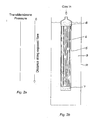
- FIG. 1a the graph shown in Figure 1a illustrates the change in transmembrane pressure (TMP) as the distance from the application of pressure flow increases.
- Figure 1b shows a membrane module 5 having a plurality of hollow fibre membranes 6. The fibre membranes 6 are closed at the lower end in a lower pot 7 and open at the upper end through upper pot 8. The module is immersed in liquid 9 contained in a vessel 10. In the case illustrated, pressurized liquid is applied to the open end of the fibre lumens 11 resulting in the TMP profile shown in Figure 1a .
- TMP transmembrane pressure
- Figures 2a and 2b show a similar arrangement to Figure 1 but in this case pressurized gas is applied to the fibre membrane lumens 11 resulting in an even distribution of TMP along the length of the fibre membranes 6.
- Figures 3a to 3c illustrates pressurized gas applied at a pressure below the bubble point to liquid filled fibre membrane lumens 11.
- the lumen 11 becomes filled with gas resulting in a maximum TMP being applied along the length of the fibre membrane 6 as the liquid level within the fibre membrane lumen 11 drops.
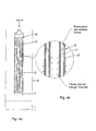
- Figure 4a and 4b illustrates liquid being drained from around the membrane module 5 before the backwashing process is commenced.
- the backwashing process is similar to that described above for Figure 3 .
- FIG. 5 one embodiment of the cleaning process according to the invention is illustrated.
- the membrane module 5 is immersed at least partially in chemical cleaning solution 13 and suction is applied to the open ends of the fibre membrane lumens 11.
- the cleaning solution 13 is drawn through the membrane wall 12 and into the fibre membrane lumen 11.
- the cleaning solution 13 is then drawn up through the lumen 11 until it is completely filled as shown in Figure 5c .
- pressurized gas is then applied to the cleaning solution filling the membrane lumen 11 and displaced through the membrane wall 12 as previously described. This flow of cleaning solution to and from the membrane lumens 11 as well as along their length results in an effective chemical clean of the membrane module 5.
- the invention may be embodied in a similar apparatus to that described in the aforementioned International Application No. WO93/02779 appropriately modified to operate in accordance with the inventive method.
Description
- The present invention relates to a method of concentrating the solids of a liquid suspension by means of permeable hollow membranes, and, in particular, to an improved method of backwashing and chemically cleaning the hollow fibre membrane.
-
JP-A-11-76769 -
US-S-4,931,186 describes a method of concentrating solids in a liquid suspension using a filter having a plurality of hollow, microporous, elastic fibres. The concentrating method includes a cleaning step which comprises stretching the fibre pores of the membrane and washing out solids retained in the pores by the application of gas under pressure. -
JP-A-10-000464 -
US 4935143 describes a method for cleaning of filters including a gaseous backwash cycle in which pressurised gas is introduced through the lumens of hollow microporous fibres and passes through the wall of the fibres to dislodge solids retained in or on the fibre walls. The gaseous cleaning step is enhanced by varying the pressure within the housing of the filter while the gas is being introduced into the filter. -
US-A-4,935,143 A1 describes a microporous filter assembly wherein feed pressure is fed to the external walls of the microporous fibres comprising the filter. Also disclosed are various forms of backwashing of the fibres. These backwash methods include terminating the supply of feed to the exterior surface of the fibres and removing the remaining filtrate from the lumens of the fibres. -
US 4,767,539 discloses a method of cleaning a filter having a plurality of porous hollow fibres contained within a housing. The filtration method includes the step of applying a liquid suspension feedstock to the outer surfaces of the fibres so that a portion of the feedstock passes through the walls of the fibres to be drawn from the fibre as a filtrate. During this process, some of the feedstock is retained in the pores of the fibres. This retained feedstock is dislodged by introducing a pressurised gas into the fibres that passes through the fibre walls. -
GB 2,120,952 -
JP 10028845 - Any discussion of the prior art throughout the specification should in no way be considered as an admission that such prior art is widely known or forms part of the common general knowledge in the field.
- Known backwash systems include those described in our earlier International Application no.
WO93/02779 - A pressurized liquid backwash of hollow fibre membranes has been found to be uneven along the length of the fibre membranes due to the frictional losses along the lumen. In membranes with the fibres closed at one end, the pressure of liquid is highest at the point of application of the pressurized flow to the fibres lumens and tapering off along the length of the membrane. This results in uneven backwashing and poor recovery of TMP at portions of the fibres remote from the backwash application point. In fibres open at both ends, the backwash flow is a minimum towards the centre of the fibre.
- During chemical cleaning of membranes, cleaning solutions are often backflushed from the lumen side of the membrane to distribute the cleaning solution within the membrane fibre bundle. Applying the cleaning solution under pressure assists the removal of foulants from the surface. However, the limitations of pressure drop down the lumen during this step mean that achieving the same applied transmembrane pressure (TMP) to all areas of the membrane cannot be readily achieved, especially for small diameter fibres where the pressure loss is greatest. This impacts on the efficiency of cleaning.
- It is an object of the invention to overcome or at least ameliorate one or more of the disadvantages of the prior art or at least provide a useful alternative.
- According to a first aspect of the invention there is provided a method as recited in claim 1.
- The backwash includes use of clean-in-place (CIP) chemical solutions instead of the filtrate. This may be employed in a number of different backwash methods.
- The backwash method includes filtering the chemical cleaning solution from the shell side, that is, from the outer surface or vessel side of the membrane into the membrane lumens. The normal backwash is then performed and the chemical solution forced back through the membrane pores in an even fashion by applying a gas as described above.
- One form of the chemical backwash includes applying chemical cleaning solution under pressure to the outer side of the membranes to force chemical cleaning solution through the membrane pores and fill the membrane lumens with the chemical cleaning solution. This is followed by the normal gas backwash described above.
- In order to minimise the volume of chemical cleaning solution used all (or most) of the liquid in the system may be removed or drained from one side of the membrane, typically the filtrate side (or inside of the hollow membrane), then the outer side of the membrane is at least partially filled with chemical cleaning solution and a vacuum (or reduced pressure) applied to the filtrate side to cause the chemical cleaning solution to be drawn from the outer side of the membrane to the filtrate side, then gas pressure is applied to the filtrate side to force the chemical cleaning solution in the reverse direction from the filtrate side through the membrane wall back to the outer side of the membrane.
- In another method, the filtrate side of the membrane(s) is drained or emptied of liquid and liquid on the outer side of the membranes is also partially drained or emptied. The outer side of the membrane lumen is then at least partially filled chemical cleaning solution. The chemical cleaning solution applied to the outer side of the membranes is then pushed through with gas (for a pressurized system) or drawn through under suction (for a submerged non-pressurized system) to fill the lumen with chemical cleaning solution and the volume of chemical cleaning solution used is less than the hold-up volume of liquid on the outer side of the membranes. Only enough volume of chemical cleaning solution on the outer side of the membranes to fill the membrane lumens is required. Pressure can then be applied to the lumen side to drain the chemical cleaning solution from the lumen by pushing it back through the membrane wall. This cycle can be repeated multiple times so that the chemical cleaning solution is alternately moved from one side of the membrane to the other through the membrane wall.
- Each of the above chemical cleaning methods has been found to provide a more efficient chemical backwash. The methods allow for a minimal use of chemical cleaning solution while also enabling an enhanced washing process by providing a more efficient distribution of the chemical cleaning solution within the system. Desirably, these backwashes or cleans are performed on an intermittent basis.
- Using the methods described the reverse flow cleaning step can be accomplished in such a way as to allow the transmembrane pressure (TMP) to be controlled by the gas pressure and to apply this TMP evenly along the membrane, even at the extremities from the lumen inlet. This ensures all areas of the membrane are contacted with chemical cleaning solution and that they are back-flushed with the same applied TMP. It also allows the chemical in the lumens to be fully drained by the end of the reverse flow step, which aids in recovery of chemical cleaning solution, reduces flushing requirements, and reduces cleaning downtime.
- In one preferred form, the gas may be pulsed in its application to the membrane lumens. In one alternate form of the chemical solution backwash described above, the backwash is performed with the vessel empty.
- The process can be applied to membranes submerged in an open vessel as well as pressurized membrane filtration systems.
- Preferred embodiments of the invention will now be described, by way of example only, with reference to the accompanying drawings in which:
-
Figure 1a shows a graph of transmembrane pressure (TMP) vs position along the membrane bundle of the membrane module configuration shown inFigure 1b ; -
Figure 1b shows a simplified sectional side elevation of a membrane module immersed in a feed liquid with pressurized liquid applied to the membrane lumens ; -
Figure 2a shows a graph of transmembrane pressure (TMP) vs position along the membrane bundle of the membrane module configuration shown inFigure 2b ; -
Figure 2b shows a simplified sectional side elevation of a membrane module immersed in a feed liquid with pressurized gas applied to the membrane lumens ; -
Figure 3a shows a graph of transmembrane pressure (TMP) vs position along the membrane bundle of the membrane module configuration shown inFigure 3b ; -
Figure 3b shows a simplified sectional side elevation of a membrane module immersed in a feed liquid with pressurized gas applied to liquid filled membrane lumens ; -
Figure 3c shows an enlarged sectional view of the membranes in the indicated region ofFigure 3b ; -
Figure 4a shows a simplified sectional side elevation of a membrane module with the feed liquid drained from around the module ; -
Figure 4b shows an enlarged sectional view of the membranes in the indicated region ofFigure 4b ; -
Figure 5a shows a simplified sectional side elevation of a membrane module with a lower portion of the module immersed in a chemical cleaning solution and suction applied to the membrane lumens ; -
Figure 5b shows an enlarged sectional view of the membranes in the indicated region ofFigure 5a ; -
Figure 5c shows an enlarged sectional view of the membranes in the indicated region ofFigure 5a ; -
Figure 6a shows a simplified sectional side elevation of a membrane module with a lower portion of the module immersed in a chemical cleaning solution and pressurized gas applied to the membrane lumens ; and -
Figure 6b shows an enlarged sectional view of the membranes in the indicated region ofFigure 6a . - Referring to
Figures 1 a and 1b, the graph shown inFigure 1a illustrates the change in transmembrane pressure (TMP) as the distance from the application of pressure flow increases.Figure 1b shows amembrane module 5 having a plurality ofhollow fibre membranes 6. Thefibre membranes 6 are closed at the lower end in alower pot 7 and open at the upper end throughupper pot 8. The module is immersed inliquid 9 contained in avessel 10. In the case illustrated, pressurized liquid is applied to the open end of the fibre lumens 11 resulting in the TMP profile shown inFigure 1a . - As noted above, in membranes with the
fibre membranes 6 closed at one end, the pressure of liquid is highest at the point of application of the pressurized flow to the fibres lumens 11 and tapers off along the length of themembrane 6. This results in uneven backwashing and poor recovery of TMP at portions of thefibre membranes 6 remote from the backwash application point. -
Figures 2a and 2b show a similar arrangement toFigure 1 but in this case pressurized gas is applied to the fibre membrane lumens 11 resulting in an even distribution of TMP along the length of thefibre membranes 6. -
Figures 3a to 3c illustrates pressurized gas applied at a pressure below the bubble point to liquid filled fibre membrane lumens 11. As best shown inFigure 3c as the liquid is displaced through themembrane wall 12, the lumen 11 becomes filled with gas resulting in a maximum TMP being applied along the length of thefibre membrane 6 as the liquid level within the fibre membrane lumen 11 drops. -
Figure 4a and 4b illustrates liquid being drained from around themembrane module 5 before the backwashing process is commenced. The backwashing process is similar to that described above forFigure 3 . - Referring to
Figures 5 and6 , one embodiment of the cleaning process according to the invention is illustrated. Themembrane module 5 is immersed at least partially inchemical cleaning solution 13 and suction is applied to the open ends of the fibre membrane lumens 11. As best shown infigure 5b , thecleaning solution 13 is drawn through themembrane wall 12 and into the fibre membrane lumen 11. Thecleaning solution 13 is then drawn up through the lumen 11 until it is completely filled as shown inFigure 5c . As shown inFigures 6a and 6b , pressurized gas is then applied to the cleaning solution filling the membrane lumen 11 and displaced through themembrane wall 12 as previously described. This flow of cleaning solution to and from the membrane lumens 11 as well as along their length results in an effective chemical clean of themembrane module 5. - The invention may be embodied in a similar apparatus to that described in the aforementioned International Application No.
WO93/02779
Claims (4)
- A method of concentrating the solids of a liquid suspension comprising:(i) providing a pressure differential across the walls of permeable, hollow membranes immersed in the liquid suspension, said liquid suspension being applied to the outer surface of the porous hollow membranes to induce and sustain filtration through the membrane walls wherein:(a) some of the liquid suspension passes through the walls of the membranes to be drawn off as clarified liquid or filtrate from the hollow membrane lumens, and(b) at least some of the solids are retained on or in the hollow membranes or otherwise as suspended solids within the liquid surrounding the membranes.(ii) periodically backwashing the membrane pores using the filtrate by applying a gas at a pressure below the bubble point to the membrane lumens to progressively displace at least some of liquid filtrate within the lumens through the membrane pores resulting in removal of the solids retained on or in the hollow membranes into the bulk liquid surrounding the membranes;
wherein the backwashing step includes the use of a chemical cleaning solution instead of the filtrate comprising filtering the chemical cleaning solution from the outer surface of the porous hollow membranes into the membrane lumens and then displacing said chemical cleaning solution back through the membrane pores by application of said gas;
the method further includes the step of removing at least part of the bulk liquid surrounding the membranes prior to the backwashing step; and,
the step of removing at least part of the liquid remaining in the membrane lumens prior to displacing chemical cleaning solution into the membrane lumens. - A method of concentrating the solids of a liquid suspension according to claim 1 wherein said method is carried out as a continuous process utilizing the repetitive cycle of solid accumulation and solid displacement or removal.
- A method of concentrating the solids of a liquid suspension according to claim 1 or 2 including the step of applying the chemical cleaning solution under pressure to the outer surface of the porous hollow membranes to displace chemical cleaning solution through the membrane pores into the membrane lumens and then displacing said chemical cleaning solution back through the membrane pores by application of said gas.
- A method of concentrating the solids of a liquid suspension according to any one of the preceding claims wherein the gas is pulsed in its application to the membrane lumens.
Applications Claiming Priority (2)
| Application Number | Priority Date | Filing Date | Title |
|---|---|---|---|
| AU2003905174A AU2003905174A0 (en) | 2003-09-22 | Backwash and cleaning method | |
| PCT/AU2004/001292 WO2005028086A1 (en) | 2003-09-22 | 2004-09-22 | Backwash and cleaning method |
Publications (3)
| Publication Number | Publication Date |
|---|---|
| EP1680211A1 EP1680211A1 (en) | 2006-07-19 |
| EP1680211A4 EP1680211A4 (en) | 2007-10-17 |
| EP1680211B1 true EP1680211B1 (en) | 2014-07-09 |
Family
ID=34318307
Family Applications (1)
| Application Number | Title | Priority Date | Filing Date |
|---|---|---|---|
| EP04761327.8A Active EP1680211B1 (en) | 2003-09-22 | 2004-09-22 | Backwash and cleaning method |
Country Status (9)
| Country | Link |
|---|---|
| US (1) | US20070034569A1 (en) |
| EP (1) | EP1680211B1 (en) |
| JP (2) | JP4846584B2 (en) |
| KR (1) | KR101141514B1 (en) |
| CN (1) | CN100450594C (en) |
| CA (1) | CA2533505C (en) |
| NZ (1) | NZ544864A (en) |
| SG (1) | SG120409A1 (en) |
| WO (1) | WO2005028086A1 (en) |
Families Citing this family (38)
| Publication number | Priority date | Publication date | Assignee | Title |
|---|---|---|---|---|
| AUPR421501A0 (en) | 2001-04-04 | 2001-05-03 | U.S. Filter Wastewater Group, Inc. | Potting method |
| AUPR692401A0 (en) | 2001-08-09 | 2001-08-30 | U.S. Filter Wastewater Group, Inc. | Method of cleaning membrane modules |
| AUPS300602A0 (en) | 2002-06-18 | 2002-07-11 | U.S. Filter Wastewater Group, Inc. | Methods of minimising the effect of integrity loss in hollow fibre membrane modules |
| CA2501628C (en) | 2002-10-10 | 2012-12-04 | U.S. Filter Wastewater Group, Inc. | A filtration and backwashing arrangement for membrane modules |
| CN103285737B (en) | 2003-08-29 | 2016-01-13 | 伊沃夸水处理技术有限责任公司 | Backwash |
| CN100421772C (en) | 2003-11-14 | 2008-10-01 | 西门子水技术公司 | Improved module cleaning method |
| WO2005092799A1 (en) | 2004-03-26 | 2005-10-06 | U.S. Filter Wastewater Group, Inc. | Process and apparatus for purifying impure water using microfiltration or ultrafiltration in combination with reverse osmosis |
| EP1807180B1 (en) | 2004-09-07 | 2013-02-13 | Siemens Industry, Inc. | Reduction of backwash liquid waste |
| CA2579857A1 (en) | 2004-09-14 | 2006-03-23 | Siemens Water Technologies Corp. | Membrane filtration module and cleaning process |
| CA2579894A1 (en) | 2004-09-15 | 2006-03-23 | Siemens Water Technologies Corp. | Continuously variable aeration |
| SG150505A1 (en) | 2004-12-24 | 2009-03-30 | Siemens Water Tech Corp | Cleaning in membrane filtration systems |
| CA2591580A1 (en) | 2004-12-24 | 2006-06-29 | Siemens Water Technologies Corp. | Simple gas scouring method and apparatus |
| KR20080005993A (en) * | 2005-04-29 | 2008-01-15 | 지멘스 워터 테크놀로지스 코포레이션 | Chemical clean for membrane filter |
| KR20080045231A (en) | 2005-08-22 | 2008-05-22 | 지멘스 워터 테크놀로지스 코포레이션 | An assembly for water filtration using a tube manifold to minimise backwash |
| US20090255873A1 (en) * | 2006-08-31 | 2009-10-15 | Bruce Gregory Biltoft | Low pressure backwash |
| WO2008051546A2 (en) | 2006-10-24 | 2008-05-02 | Siemens Water Technologies Corp. | Infiltration/inflow control for membrane bioreactor |
| EP2129629A1 (en) | 2007-04-02 | 2009-12-09 | Siemens Water Technologies Corp. | Improved infiltration/inflow control for membrane bioreactor |
| US9764288B2 (en) | 2007-04-04 | 2017-09-19 | Evoqua Water Technologies Llc | Membrane module protection |
| KR100775521B1 (en) * | 2007-05-09 | 2007-11-15 | 황규복 | fluorescent lamp contact terminal of liquid crystal display device |
| CN106040002B (en) | 2007-05-29 | 2020-01-10 | 懿华水处理技术有限责任公司 | Membrane cleaning using pulsed gas stripping pump |
| JP2010531218A (en) * | 2007-06-28 | 2010-09-24 | シーメンス ウォーター テクノロジース コーポレイション | Cleaning methods for simple filtration systems |
| AU2009273775B2 (en) | 2008-07-24 | 2014-11-20 | Evoqua Water Technologies Llc | Frame system for membrane filtration modules |
| AU2010101488B4 (en) | 2009-06-11 | 2013-05-02 | Evoqua Water Technologies Llc | Methods for cleaning a porous polymeric membrane and a kit for cleaning a porous polymeric membrane |
| CN102574066B (en) * | 2009-10-22 | 2015-03-18 | 旭化成化学株式会社 | Method for immersion-type washing of separation membrane device and system for immersion-type washing of separation membrane device |
| EP2563501B1 (en) | 2010-04-30 | 2019-05-15 | Evoqua Water Technologies LLC | Fluid flow distribution device |
| CN102371123A (en) * | 2010-08-24 | 2012-03-14 | 苏州立升净水科技有限公司 | On-line cleaning method of immersed hollow fiber membrane module |
| CN103118766B (en) | 2010-09-24 | 2016-04-13 | 伊沃夸水处理技术有限责任公司 | The fluid of membrane filtration system controls manifold |
| CA2850309C (en) | 2011-09-30 | 2020-01-07 | Evoqua Water Technologies Llc | Improved manifold arrangement |
| EP2760567B1 (en) | 2011-09-30 | 2021-12-01 | Rohm & Haas Electronic Materials Singapore Pte. Ltd | Isolation valve |
| JP6013457B2 (en) * | 2012-03-27 | 2016-10-25 | メタウォーター株式会社 | Horizontal membrane filtration device |
| EP2866922B1 (en) | 2012-06-28 | 2018-03-07 | Evoqua Water Technologies LLC | A potting method |
| US9962865B2 (en) | 2012-09-26 | 2018-05-08 | Evoqua Water Technologies Llc | Membrane potting methods |
| EP2900356A1 (en) | 2012-09-27 | 2015-08-05 | Evoqua Water Technologies LLC | Gas scouring apparatus for immersed membranes |
| WO2015050764A1 (en) | 2013-10-02 | 2015-04-09 | Evoqua Water Technologies Llc | A method and device for repairing a membrane filtration module |
| CN107847869B (en) | 2015-07-14 | 2021-09-10 | 罗门哈斯电子材料新加坡私人有限公司 | Aeration device for a filtration system |
| JP6653154B2 (en) * | 2015-10-08 | 2020-02-26 | 株式会社クラレ | Cleaning method and filtration device for hollow fiber membrane module |
| MY186114A (en) * | 2016-03-04 | 2021-06-22 | Mitsubishi Electric Corp | Membrane filtration device, filtration membrane cleaning method, and method for manufacturing filtration membrane |
| CN109954714B (en) * | 2019-04-19 | 2020-12-15 | 业成科技(成都)有限公司 | Cleaning method and cleaning device for porous elastic fiber |
Family Cites Families (20)
| Publication number | Priority date | Publication date | Assignee | Title |
|---|---|---|---|---|
| JPS53108882A (en) * | 1977-03-04 | 1978-09-22 | Kuraray Co Ltd | Back washing method for hollow filament membrane |
| US4540490A (en) * | 1982-04-23 | 1985-09-10 | Jgc Corporation | Apparatus for filtration of a suspension |
| JPH0657302B2 (en) * | 1983-07-13 | 1994-08-03 | 株式会社東芝 | Backwashing method for hollow fiber membrane filters |
| JPH0659393B2 (en) | 1983-09-30 | 1994-08-10 | メムテツク リミテツド | Filter cleaning method |
| ATE81796T1 (en) * | 1985-03-05 | 1992-11-15 | Memtec Ltd | CONCENTRATION OF SOLIDS IN A SUSPENSION. |
| WO1986005705A1 (en) * | 1985-03-28 | 1986-10-09 | Memtec Limited | Cooling hollow fibre cross-flow separators |
| US4769539A (en) * | 1986-04-03 | 1988-09-06 | Thurston William H | Electro-optical roll angle detector |
| ES2014516A6 (en) * | 1986-07-11 | 1990-07-16 | Mentec Ltd | Cleaning of filters. |
| JPS6344832A (en) * | 1986-08-11 | 1988-02-25 | 株式会社オリイ | Confectionery maker |
| JPH0671540B2 (en) * | 1988-12-20 | 1994-09-14 | 株式会社東芝 | Cleaning method of hollow fiber membrane filter |
| US5643455A (en) * | 1991-08-07 | 1997-07-01 | Memtel Limited | Concentration of solids in a suspension using hollow fibre membranes |
| AUPM800694A0 (en) * | 1994-09-09 | 1994-10-06 | Memtec Limited | Cleaning of hollow fibre membranes |
| JPH10464A (en) * | 1996-06-18 | 1998-01-06 | Mitsubishi Heavy Ind Ltd | Reverse osmosis apparatus for freshening seawater |
| JPH1028845A (en) * | 1996-07-17 | 1998-02-03 | Kanegafuchi Chem Ind Co Ltd | Housing of hollow fiber membrane cartridge filter and backwashing thereof |
| JP3887072B2 (en) * | 1997-02-12 | 2007-02-28 | 株式会社クラレ | Method for cleaning hollow fiber membrane module and filtration device used in the method |
| JPH10328538A (en) | 1997-05-29 | 1998-12-15 | Japan Organo Co Ltd | Method for cleaning hollow yarn membrane filtration tower |
| JPH1176769A (en) * | 1997-09-01 | 1999-03-23 | Daicel Chem Ind Ltd | Cleaning method of filter membrane module |
| JP2000079390A (en) * | 1998-06-30 | 2000-03-21 | Kikai Kagaku Kenkyusho:Kk | Purified water production |
| JP2000237548A (en) * | 1999-02-17 | 2000-09-05 | Tokyo Denki Komusho Co Ltd | Hollow fiber membrane type heat storage tank water purifying device |
| JP4382275B2 (en) | 2000-12-15 | 2009-12-09 | 前澤工業株式会社 | Membrane module cleaning method |
-
2004
- 2004-09-22 WO PCT/AU2004/001292 patent/WO2005028086A1/en active Search and Examination
- 2004-09-22 US US10/572,971 patent/US20070034569A1/en not_active Abandoned
- 2004-09-22 EP EP04761327.8A patent/EP1680211B1/en active Active
- 2004-09-22 NZ NZ544864A patent/NZ544864A/en not_active IP Right Cessation
- 2004-09-22 JP JP2006526487A patent/JP4846584B2/en active Active
- 2004-09-22 SG SG2006001436A patent/SG120409A1/en unknown
- 2004-09-22 CN CNB2004800264894A patent/CN100450594C/en not_active Expired - Fee Related
- 2004-09-22 CA CA2533505A patent/CA2533505C/en not_active Expired - Fee Related
- 2004-09-22 KR KR1020067005571A patent/KR101141514B1/en active IP Right Grant
-
2010
- 2010-09-13 JP JP2010204344A patent/JP2011020121A/en active Pending
Also Published As
| Publication number | Publication date |
|---|---|
| JP4846584B2 (en) | 2011-12-28 |
| JP2007505728A (en) | 2007-03-15 |
| KR101141514B1 (en) | 2012-05-08 |
| CA2533505A1 (en) | 2005-03-31 |
| CN100450594C (en) | 2009-01-14 |
| JP2011020121A (en) | 2011-02-03 |
| EP1680211A4 (en) | 2007-10-17 |
| US20070034569A1 (en) | 2007-02-15 |
| WO2005028086A1 (en) | 2005-03-31 |
| NZ544864A (en) | 2010-02-26 |
| CA2533505C (en) | 2013-02-19 |
| KR20060098430A (en) | 2006-09-18 |
| CN1852760A (en) | 2006-10-25 |
| EP1680211A1 (en) | 2006-07-19 |
| SG120409A1 (en) | 2006-04-26 |
Similar Documents
| Publication | Publication Date | Title |
|---|---|---|
| EP1680211B1 (en) | Backwash and cleaning method | |
| US20100025320A1 (en) | Backwash and cleaning method | |
| EP1441841B1 (en) | Method for cleaning a high solids module | |
| EP0952885B1 (en) | Scouring method | |
| EP1799334B1 (en) | Methods and apparatus for removing solids from a membrane module | |
| EP1835985B1 (en) | Cleaning in membrane filtration systems | |
| EP1677898B1 (en) | Backwash | |
| JP4975950B2 (en) | Membrane module cleaning method | |
| JPH07185268A (en) | Hollow fiber filter membrane element and module | |
| AU2004273542B2 (en) | Backwash and cleaning method | |
| AU2002328672B2 (en) | High solids module | |
| AU2004267874B2 (en) | Backwash | |
| AU2002328672A1 (en) | High solids module |
Legal Events
| Date | Code | Title | Description |
|---|---|---|---|
| PUAI | Public reference made under article 153(3) epc to a published international application that has entered the european phase |
Free format text: ORIGINAL CODE: 0009012 |
|
| 17P | Request for examination filed |
Effective date: 20060407 |
|
| AK | Designated contracting states |
Kind code of ref document: A1 Designated state(s): AT BE BG CH CY CZ DE DK EE ES FI FR GB GR HU IE IT LI LU MC NL PL PT RO SE SI SK TR |
|
| DAX | Request for extension of the european patent (deleted) | ||
| RAP1 | Party data changed (applicant data changed or rights of an application transferred) |
Owner name: SIEMENS WATER TECHNOLOGIES CORP. |
|
| A4 | Supplementary search report drawn up and despatched |
Effective date: 20070917 |
|
| 17Q | First examination report despatched |
Effective date: 20090420 |
|
| RAP1 | Party data changed (applicant data changed or rights of an application transferred) |
Owner name: SIEMENS INDUSTRY, INC. |
|
| GRAP | Despatch of communication of intention to grant a patent |
Free format text: ORIGINAL CODE: EPIDOSNIGR1 |
|
| RAP1 | Party data changed (applicant data changed or rights of an application transferred) |
Owner name: SIEMENS WATER TECHNOLOGIES LLC |
|
| INTG | Intention to grant announced |
Effective date: 20140214 |
|
| RAP1 | Party data changed (applicant data changed or rights of an application transferred) |
Owner name: EVOQUA WATER TECHNOLOGIES LLC |
|
| GRAS | Grant fee paid |
Free format text: ORIGINAL CODE: EPIDOSNIGR3 |
|
| GRAA | (expected) grant |
Free format text: ORIGINAL CODE: 0009210 |
|
| AK | Designated contracting states |
Kind code of ref document: B1 Designated state(s): AT BE BG CH CY CZ DE DK EE ES FI FR GB GR HU IE IT LI LU MC NL PL PT RO SE SI SK TR |
|
| REG | Reference to a national code |
Ref country code: GB Ref legal event code: FG4D |
|
| REG | Reference to a national code |
Ref country code: CH Ref legal event code: EP Ref country code: AT Ref legal event code: REF Ref document number: 676354 Country of ref document: AT Kind code of ref document: T Effective date: 20140715 |
|
| REG | Reference to a national code |
Ref country code: IE Ref legal event code: FG4D |
|
| REG | Reference to a national code |
Ref country code: DE Ref legal event code: R096 Ref document number: 602004045435 Country of ref document: DE Effective date: 20140814 |
|
| REG | Reference to a national code |
Ref country code: NL Ref legal event code: T3 |
|
| REG | Reference to a national code |
Ref country code: AT Ref legal event code: MK05 Ref document number: 676354 Country of ref document: AT Kind code of ref document: T Effective date: 20140709 |
|
| PG25 | Lapsed in a contracting state [announced via postgrant information from national office to epo] |
Ref country code: GR Free format text: LAPSE BECAUSE OF FAILURE TO SUBMIT A TRANSLATION OF THE DESCRIPTION OR TO PAY THE FEE WITHIN THE PRESCRIBED TIME-LIMIT Effective date: 20141010 Ref country code: SE Free format text: LAPSE BECAUSE OF FAILURE TO SUBMIT A TRANSLATION OF THE DESCRIPTION OR TO PAY THE FEE WITHIN THE PRESCRIBED TIME-LIMIT Effective date: 20140709 Ref country code: FI Free format text: LAPSE BECAUSE OF FAILURE TO SUBMIT A TRANSLATION OF THE DESCRIPTION OR TO PAY THE FEE WITHIN THE PRESCRIBED TIME-LIMIT Effective date: 20140709 Ref country code: ES Free format text: LAPSE BECAUSE OF FAILURE TO SUBMIT A TRANSLATION OF THE DESCRIPTION OR TO PAY THE FEE WITHIN THE PRESCRIBED TIME-LIMIT Effective date: 20140709 Ref country code: BG Free format text: LAPSE BECAUSE OF FAILURE TO SUBMIT A TRANSLATION OF THE DESCRIPTION OR TO PAY THE FEE WITHIN THE PRESCRIBED TIME-LIMIT Effective date: 20141009 Ref country code: PT Free format text: LAPSE BECAUSE OF FAILURE TO SUBMIT A TRANSLATION OF THE DESCRIPTION OR TO PAY THE FEE WITHIN THE PRESCRIBED TIME-LIMIT Effective date: 20141110 |
|
| PG25 | Lapsed in a contracting state [announced via postgrant information from national office to epo] |
Ref country code: PL Free format text: LAPSE BECAUSE OF FAILURE TO SUBMIT A TRANSLATION OF THE DESCRIPTION OR TO PAY THE FEE WITHIN THE PRESCRIBED TIME-LIMIT Effective date: 20140709 Ref country code: AT Free format text: LAPSE BECAUSE OF FAILURE TO SUBMIT A TRANSLATION OF THE DESCRIPTION OR TO PAY THE FEE WITHIN THE PRESCRIBED TIME-LIMIT Effective date: 20140709 Ref country code: CY Free format text: LAPSE BECAUSE OF FAILURE TO SUBMIT A TRANSLATION OF THE DESCRIPTION OR TO PAY THE FEE WITHIN THE PRESCRIBED TIME-LIMIT Effective date: 20140709 |
|
| REG | Reference to a national code |
Ref country code: DE Ref legal event code: R097 Ref document number: 602004045435 Country of ref document: DE |
|
| PG25 | Lapsed in a contracting state [announced via postgrant information from national office to epo] |
Ref country code: LU Free format text: LAPSE BECAUSE OF FAILURE TO SUBMIT A TRANSLATION OF THE DESCRIPTION OR TO PAY THE FEE WITHIN THE PRESCRIBED TIME-LIMIT Effective date: 20140922 Ref country code: MC Free format text: LAPSE BECAUSE OF FAILURE TO SUBMIT A TRANSLATION OF THE DESCRIPTION OR TO PAY THE FEE WITHIN THE PRESCRIBED TIME-LIMIT Effective date: 20140709 Ref country code: SK Free format text: LAPSE BECAUSE OF FAILURE TO SUBMIT A TRANSLATION OF THE DESCRIPTION OR TO PAY THE FEE WITHIN THE PRESCRIBED TIME-LIMIT Effective date: 20140709 Ref country code: IT Free format text: LAPSE BECAUSE OF FAILURE TO SUBMIT A TRANSLATION OF THE DESCRIPTION OR TO PAY THE FEE WITHIN THE PRESCRIBED TIME-LIMIT Effective date: 20140709 Ref country code: RO Free format text: LAPSE BECAUSE OF FAILURE TO SUBMIT A TRANSLATION OF THE DESCRIPTION OR TO PAY THE FEE WITHIN THE PRESCRIBED TIME-LIMIT Effective date: 20140709 Ref country code: CZ Free format text: LAPSE BECAUSE OF FAILURE TO SUBMIT A TRANSLATION OF THE DESCRIPTION OR TO PAY THE FEE WITHIN THE PRESCRIBED TIME-LIMIT Effective date: 20140709 Ref country code: EE Free format text: LAPSE BECAUSE OF FAILURE TO SUBMIT A TRANSLATION OF THE DESCRIPTION OR TO PAY THE FEE WITHIN THE PRESCRIBED TIME-LIMIT Effective date: 20140709 Ref country code: DK Free format text: LAPSE BECAUSE OF FAILURE TO SUBMIT A TRANSLATION OF THE DESCRIPTION OR TO PAY THE FEE WITHIN THE PRESCRIBED TIME-LIMIT Effective date: 20140709 |
|
| REG | Reference to a national code |
Ref country code: CH Ref legal event code: PL |
|
| PLBE | No opposition filed within time limit |
Free format text: ORIGINAL CODE: 0009261 |
|
| STAA | Information on the status of an ep patent application or granted ep patent |
Free format text: STATUS: NO OPPOSITION FILED WITHIN TIME LIMIT |
|
| 26N | No opposition filed |
Effective date: 20150410 |
|
| REG | Reference to a national code |
Ref country code: IE Ref legal event code: MM4A |
|
| REG | Reference to a national code |
Ref country code: FR Ref legal event code: ST Effective date: 20150529 |
|
| PG25 | Lapsed in a contracting state [announced via postgrant information from national office to epo] |
Ref country code: BE Free format text: LAPSE BECAUSE OF NON-PAYMENT OF DUE FEES Effective date: 20140930 |
|
| REG | Reference to a national code |
Ref country code: HU Ref legal event code: AG4A Ref document number: E023160 Country of ref document: HU |
|
| PG25 | Lapsed in a contracting state [announced via postgrant information from national office to epo] |
Ref country code: LI Free format text: LAPSE BECAUSE OF NON-PAYMENT OF DUE FEES Effective date: 20140930 Ref country code: CH Free format text: LAPSE BECAUSE OF NON-PAYMENT OF DUE FEES Effective date: 20140930 |
|
| PG25 | Lapsed in a contracting state [announced via postgrant information from national office to epo] |
Ref country code: IE Free format text: LAPSE BECAUSE OF NON-PAYMENT OF DUE FEES Effective date: 20140922 Ref country code: FR Free format text: LAPSE BECAUSE OF NON-PAYMENT OF DUE FEES Effective date: 20140930 |
|
| PGFP | Annual fee paid to national office [announced via postgrant information from national office to epo] |
Ref country code: HU Payment date: 20140908 Year of fee payment: 11 |
|
| PG25 | Lapsed in a contracting state [announced via postgrant information from national office to epo] |
Ref country code: SI Free format text: LAPSE BECAUSE OF FAILURE TO SUBMIT A TRANSLATION OF THE DESCRIPTION OR TO PAY THE FEE WITHIN THE PRESCRIBED TIME-LIMIT Effective date: 20140709 |
|
| PG25 | Lapsed in a contracting state [announced via postgrant information from national office to epo] |
Ref country code: BE Free format text: LAPSE BECAUSE OF FAILURE TO SUBMIT A TRANSLATION OF THE DESCRIPTION OR TO PAY THE FEE WITHIN THE PRESCRIBED TIME-LIMIT Effective date: 20140709 Ref country code: TR Free format text: LAPSE BECAUSE OF FAILURE TO SUBMIT A TRANSLATION OF THE DESCRIPTION OR TO PAY THE FEE WITHIN THE PRESCRIBED TIME-LIMIT Effective date: 20140709 |
|
| PG25 | Lapsed in a contracting state [announced via postgrant information from national office to epo] |
Ref country code: HU Free format text: LAPSE BECAUSE OF NON-PAYMENT OF DUE FEES Effective date: 20150923 |
|
| PGFP | Annual fee paid to national office [announced via postgrant information from national office to epo] |
Ref country code: DE Payment date: 20180815 Year of fee payment: 15 Ref country code: NL Payment date: 20180829 Year of fee payment: 15 |
|
| REG | Reference to a national code |
Ref country code: DE Ref legal event code: R119 Ref document number: 602004045435 Country of ref document: DE |
|
| REG | Reference to a national code |
Ref country code: NL Ref legal event code: MM Effective date: 20191001 |
|
| PG25 | Lapsed in a contracting state [announced via postgrant information from national office to epo] |
Ref country code: DE Free format text: LAPSE BECAUSE OF NON-PAYMENT OF DUE FEES Effective date: 20200401 Ref country code: NL Free format text: LAPSE BECAUSE OF NON-PAYMENT OF DUE FEES Effective date: 20191001 |
|
| REG | Reference to a national code |
Ref country code: GB Ref legal event code: 732E Free format text: REGISTERED BETWEEN 20200827 AND 20200902 |
|
| P01 | Opt-out of the competence of the unified patent court (upc) registered |
Effective date: 20230530 |
|
| PGFP | Annual fee paid to national office [announced via postgrant information from national office to epo] |
Ref country code: GB Payment date: 20230803 Year of fee payment: 20 |