EP1679775A1 - Busbar - Google Patents
Busbar Download PDFInfo
- Publication number
- EP1679775A1 EP1679775A1 EP05027992A EP05027992A EP1679775A1 EP 1679775 A1 EP1679775 A1 EP 1679775A1 EP 05027992 A EP05027992 A EP 05027992A EP 05027992 A EP05027992 A EP 05027992A EP 1679775 A1 EP1679775 A1 EP 1679775A1
- Authority
- EP
- European Patent Office
- Prior art keywords
- busbar according
- busbar
- connection
- plane
- longitudinal member
- Prior art date
- Legal status (The legal status is an assumption and is not a legal conclusion. Google has not performed a legal analysis and makes no representation as to the accuracy of the status listed.)
- Granted
Links
Images

Classifications
-
- H—ELECTRICITY
- H02—GENERATION; CONVERSION OR DISTRIBUTION OF ELECTRIC POWER
- H02B—BOARDS, SUBSTATIONS OR SWITCHING ARRANGEMENTS FOR THE SUPPLY OR DISTRIBUTION OF ELECTRIC POWER
- H02B1/00—Frameworks, boards, panels, desks, casings; Details of substations or switching arrangements
- H02B1/20—Bus-bar or other wiring layouts, e.g. in cubicles, in switchyards
- H02B1/205—Bus-bar or other wiring layouts, e.g. in cubicles, in switchyards for connecting electrical apparatus mounted side by side on a rail
Definitions
- the invention relates to a busbar for the simultaneous phased feeding of several juxtaposed modular switching devices in an electrical installation distribution according to the generic part of claim 1.
- Object of the present invention is therefore to develop a power bus of the generic type so that even with immediately adjacent terminals modern switchgear for the necessary directly adjacent busbars trouble-free connection wiring in one of the provided for the terminal lugs of the busbar recesses of the terminals is possible.
- the power bus according to the invention should be easy to manufacture and easy to install.
- connection plane of the busbar formed by the longitudinal member and the connecting plane of the busbar formed jointly by the connecting tabs are separated from one another are spaced apart parallel to each other, wherein the terminal plates are connected by connecting webs with the side rail.
- the ribbon-shaped longitudinal member of the busbar which establishes the connection between the individual terminal straps and defines the connection plane, is laterally removed from the region of the terminal straps fixed directly in the terminals of the switching devices.
- the bus bar thus has a first formed by the flat band-shaped side rail connecting portion (connection plane) from which projecting individual connecting webs at right angles, wherein the connecting webs are in turn bent at right angles to the terminal lugs, which form the so-called terminal level in their entirety.
- the connecting webs at least on their side facing away from the terminal straps top cover by an insulating hood. In this way, a contact of current leading parts of the busbar in the installed state is reliably excluded.
- the insulating hood can at its end facing away from the ribbon-shaped longitudinal beam end in the region of the outlet of the respective terminal lug a Have recess, which is preferably designed arcuate.
- the recess is used, if necessary, to insert a connection wire directly under the insulating hood parallel to the corresponding connection lug into a connection terminal of a switching device in particularly cramped space conditions.
- Switchgear with predetermined different distances of the terminals in the range of 4 to 12 mm can hereby be connected to two busbars with different power supply, if the connecting webs have a length in the range of 4 to 12 mm.
- the busbar may further comprise a fixed number of 2 to 13 terminal lugs, and furthermore a multiple of each of 2 to 13 terminal latches, i. z. B. 26 or 39 connecting straps for corresponding applications are advantageous.
- FIG. 1 schematically shows three modular switching devices 1, 2, 3 of an electrical installation distribution.
- the switching devices are set to a mounting rail, not shown here, with a variety of switching devices, whose representation has also been omitted here for reasons of clarity, are arranged side by side in the rule.
- each switching device 1, 2, 3 on its upper side facing the viewer each have two terminals 4 and 5 provided with recesses. These recesses are provided for receiving connecting straps of busbars.
- the terminals 4 are located on a common dash-dotted line 8 and are acted upon by a busbar 6 together with power.
- the terminals 5 of the switching devices 1, 2, 3 are also located on a common dash-dotted line 9 and are acted upon by a busbar 7 with power.
- connection plane V the connection plane of the busbar.
- connecting lugs 11 which are connected to the side rail 10 by connecting webs 12.
- connection area remains directly above the terminals 4, 5 of the switching devices 1, 2, 3, in contrast to known from the prior art busbars freely accessible, so that here, if necessary, a necessary Connection wiring in one of the terminals 4, 5 can be easily made.
- connection webs 12 are each angled perpendicular to both the terminal lug 11 and the longitudinal member 10, so that there is a double-L-shaped cross-sectional configuration of the busbars 6, 7.
- connection plane A and the connecting plane V are arranged at a distance from each other in parallel.
- the longitudinal member 10 is enclosed by an insulating sleeve 13, with cover caps 14 adjoining the insulating sleeve 13 in the region of the respective connecting webs 12, covering the connecting web 12 on its upper side facing away from the connecting tabs 11 .
- This design is used for insulation according to international classification IP 20, since after insertion of the busbars 6, 7 with their respective terminal lugs 11 in the terminals 4, 5 of the switching devices 1, 2 3 no longer has possibility, current-carrying parts of Stormsammelschiene with his finger to touch.
- the covers 14 of the connecting webs 12 and the insulating sheath 13 of the longitudinal member 10 are advantageously produced in one piece as part of an injection molding process and can have different color design for different busbar applications.
- each end between two adjacent terminal lugs 11 has a substantially rectangular recess 17 formed.
- the connecting webs 12 can engage with the covering cover 14 covering them in the indentations 17 of the adjacent busbar.
- the distance between two adjacent busbars 6 and 7 can thus be easily different lateral distances of the terminals 4, 5 of the switching devices 1, 2, 3 adapt.
- distances between the lines 8 and 9 defined by the connection terminals 4 and 5 can be compensated from 4 to 11 mm.
Abstract
Description
Die Erfindung betrifft eine Stromsammelschiene zur gleichzeitigen phasenweisen Speisung mehrerer nebeneinander angeordneter modularer Schaltgeräte in einer elektrischen Installationsverteilung gemäss dem gattungsbildenden Teil des Anspruches 1.The invention relates to a busbar for the simultaneous phased feeding of several juxtaposed modular switching devices in an electrical installation distribution according to the generic part of
Stromsammelschienen der genannten Art werden weltweit in unterschiedlicher Ausgestaltung eingesetzt und haben sich prinzipiell für die kostengünstige elektrische Verbindung modularer Schaltgeräte bewährt. Die Schaltgeräte unterliegen dabei auf Grund technischer Weiterentwicklungen sowie geänderter gesetzlicher Vorgaben häufigen baulichen Änderungen. Hinzu kommt die allgemeine Anforderung der Baugrößenreduzierung derartiger Geräte, die dazu führt, dass auch die zur Aufnahme der Anschlusslaschen der einzelnen Stromsammelschienen vorgesehenen Ausnehmungen der Anschlussklemmen an den einzelnen Schaltgeräten der elektrischen Installationsverteilung immer näher zusammenrücken.Current busbars of the type mentioned are used worldwide in different configurations and have proven in principle for the cost-effective electrical connection of modular switchgear. The switching devices are subject to frequent structural changes due to technical developments as well as changed legal requirements. In addition, there is the general requirement of reducing the size of such devices, which means that the recesses provided for receiving the terminal lugs of the individual busbars closer together ever closer to the individual switching devices of the electrical installation distribution.
Zwar ist es zum gegenwärtigen Zeitpunkt noch möglich, mittels der aus dem Stand der Technik bekannten Stromsammelschienen durch Übereinanderanordnung von Letzteren die Verbindung der Anschlüsse der einzelnen Schaltgeräte vorzunehmen, jedoch ergibt sich durch das zwangsläufige Zusammenrücken der parallel übereinander angeordneten Stromsammelschienen die Problematik, dass der notwendige Drahtanschluss der Stromsammelschienen, der in einer der Anschlussklemmen für die Anschlusslaschen der Stromsammelschienen in einer der verbundenen Schaltgeräte zusätzlich eingeklemmt werden muss, platzmäßig nur noch unter größten Schwierigkeiten zu realisieren ist.Although it is still possible at the present time, by means of the known from the prior art busbars by superposition of the latter to make the connection of the terminals of the individual switching devices, however, results from the inevitable moving together in parallel arranged busbars the problem that the necessary wire connection of the busbars, which must be additionally clamped in one of the terminals for the terminal lugs of the busbars in one of the connected switching devices, space only with great difficulty to realize.
Bei zwei parallel übereinander angeordneten Stromsammelschienen ist es nämlich erforderlich, dass mindestens ein Anschluss einer Stromsammelschiene zwischen den beiden zueinander weisenden Flachseiten der benachbarten Stromsammelschienen hindurchgeführt und in einer Ausnehmung einer Anschlussklemme eines Schaltgerätes zusammen mit einer Anschlusslasche in üblicher Weise durch einen geeigneten Klemmmechanismus fixiert wird. Da der Abstand der zueinander weisenden Flachseiten auf Grund der geänderten Bauabmaße moderner Schaltgeräte unter Umständen nur noch im Bereich von 1 bis 2 mm liegt, ergeben sich zwangsläufig für die Verdrahtung in Folge der notwendigen Drahtdurchmesser große Anschlussschwierigkeiten.In the case of two busbars arranged parallel one above the other, it is necessary for at least one terminal of a busbar to be passed between the two mutually facing flat sides of the adjacent busbars and fixed in a recess of a terminal of a switching device together with a terminal lug in the usual way by a suitable clamping mechanism. Since the distance of the mutually facing flat sides due to the changed dimensions of modern switchgear under certain circumstances only in the range of 1 to 2 mm, inevitably arise for the wiring as a result of the necessary wire diameter large connection difficulties.
Aufgabe der vorliegenden Erfindung ist es daher, eine Stromsammelschiene der gattungsgemäßen Art so weiter zu entwickeln, dass auch bei unmittelbar nebeneinander liegenden Anschlüssen moderner Schaltgeräte für die dadurch notwendigen unmittelbar nebeneinander befindlichen Stromsammelschienen eine problemlose Anschlussverdrahtung in einer der für die Anschlusslaschen der Stromsammelschiene vorgesehenen Ausnehmungen der Anschlussklemmen möglich ist. Darüber hinaus soll die erfindungsgemäße Stromsammelschiene einfach herstellbar und leicht montierbar sein.Object of the present invention is therefore to develop a power bus of the generic type so that even with immediately adjacent terminals modern switchgear for the necessary directly adjacent busbars trouble-free connection wiring in one of the provided for the terminal lugs of the busbar recesses of the terminals is possible. In addition, the power bus according to the invention should be easy to manufacture and easy to install.
Diese Aufgabe wird erfindungsgemäß in Zusammenschau mit den gattungsbildenden Merkmalen durch die im kennzeichnenden Teil des Anspruches 1 offenbarte technische Lehre gelöst.This object is achieved according to the invention in conjunction with the generic features by the disclosed in the characterizing part of
Wesentlich für die Erfindung ist es dabei, dass die durch den Längsträger gebildete Verbindungsebene der Stromsammelschiene und die durch die Anschlusslaschen gemeinsam gebildete Anschlussebene der Stromsammelschiene voneinander getrennt parallel beabstandet zueinander angeordnet sind, wobei die Anschlusslaschen durch Verbindungsstege mit dem Längsträger verbunden sind.It is essential for the invention in this case that the connection plane of the busbar formed by the longitudinal member and the connecting plane of the busbar formed jointly by the connecting tabs are separated from one another are spaced apart parallel to each other, wherein the terminal plates are connected by connecting webs with the side rail.
Durch diese erfindungsgemäße Gestaltung wird der flachbandförmige Längsträger der Stromsammelschiene, welcher die Verbindung zwischen den einzelnen Anschlusslaschen herstellt und die Verbindungsebene definiert, seitlich aus dem Bereich der unmittelbar in den Anschlussklemmen der Schaltgeräte festgelegten Anschlusslaschen entfernt. Hierdurch kann im Gegensatz zu üblichen aus dem Stand der Technik bekannten Stromsammelschienen nunmehr durch die Tatsache, dass der Bereich über den Anschlusslaschen freigehalten ist, eine Anschlussverdrahtung ohne Platzprobleme direkt in eine der Anschlussklemmen eines Schaltgerätes erfolgen.By means of this design according to the invention, the ribbon-shaped longitudinal member of the busbar, which establishes the connection between the individual terminal straps and defines the connection plane, is laterally removed from the region of the terminal straps fixed directly in the terminals of the switching devices. As a result, in contrast to conventional busbars known from the prior art, a connection wiring without space problems can now be made directly into one of the terminals of a switching device by virtue of the fact that the area above the terminal latches is kept free.
Besondere Ausgestaltung des Gegenstandes der Erfindung ergeben sich zusammen mit der technischen Lehre des Anspruches 1 zusätzlich aus den Merkmalen der rückbezogenen Unteransprüche.Particular embodiment of the subject of the invention will become apparent, together with the technical teaching of
Es hat sich insbesondere als vorteilhaft erwiesen, zur Platzeinsparung im Bereich der Anschlüsse der Schaltgeräte die Verbindungsstege im Wesentlichen rechtwinklig zur Anschlussebene und zur Verbindungsebene der Stromsammelschiene anzuordnen. Im Querschnitt weist die Stromsammelschiene somit einen ersten durch den flachbandförmigen Längsträger gebildeten Verbindungsbereich (Verbindungsebene) auf, aus dem rechtwinklig einzelne Verbindungsstege hervorstehen, wobei die Verbindungsstege wiederum rechtwinklig zu den Anschlusslaschen umgebogen sind, die in ihrer Gesamtheit die so genannte Anschlussebene bilden.In particular, it has proved to be advantageous to arrange the connecting webs essentially at right angles to the connection plane and to the connection plane of the current collecting rail in order to save space in the area of the connections of the switching devices. In cross-section, the bus bar thus has a first formed by the flat band-shaped side rail connecting portion (connection plane) from which projecting individual connecting webs at right angles, wherein the connecting webs are in turn bent at right angles to the terminal lugs, which form the so-called terminal level in their entirety.
Zusätzlich vorteilhaft und auf Grund von Sicherheitsaspekten geboten ist darüber hinaus die Ausgestaltung, die Verbindungsstege mindestens an ihrer den Anschlusslaschen abgewandten Oberseite durch eine Isolierhaube abzudecken. Auf diese Weise wird eine Berührung Strom führender Teile der Stromsammelschiene im eingebauten Zustand zuverlässig ausgeschlossen.In addition, it is advantageous and due to safety aspects offered the embodiment, the connecting webs at least on their side facing away from the terminal straps top cover by an insulating hood. In this way, a contact of current leading parts of the busbar in the installed state is reliably excluded.
Die Isolierhaube kann dabei an ihrem dem flachbandförmigen Längsträger abgewandten Ende im Bereich des Austritts der jeweiligen Anschlusslasche eine Ausnehmung aufweisen, die vorzugsweise bogenförmig gestaltet ist. Die Ausnehmung dient dazu, gegebenenfalls bei besonders beengten Platzverhältnissen einen Anschlussdraht unmittelbar unter der Isolierhaube parallel zur entsprechenden Anschlusslasche in eine Anschlussklemme eines Schaltgerätes einzuführen.The insulating hood can at its end facing away from the ribbon-shaped longitudinal beam end in the region of the outlet of the respective terminal lug a Have recess, which is preferably designed arcuate. The recess is used, if necessary, to insert a connection wire directly under the insulating hood parallel to the corresponding connection lug into a connection terminal of a switching device in particularly cramped space conditions.
Schaltgeräte mit vorgegebenen verschiedenen Abständen der Anschlussklemmen im Bereich von 4 bis 12 mm können hierbei mit zwei Sammelschienen mit verschiedener Stromführung verbunden werden, wenn die Verbindungsstege eine Länge im Bereich von 4 bis 12 mm aufweisen. Mit dieser Maßnahme lassen sich die erfindungsgemäßen Stromsammelschienen für alle herkömmlichen (L1/N = 2polig) Schaltgeräte verwenden.Switchgear with predetermined different distances of the terminals in the range of 4 to 12 mm can hereby be connected to two busbars with different power supply, if the connecting webs have a length in the range of 4 to 12 mm. With this measure, the current busbars according to the invention can be used for all conventional (L1 / N = 2-pole) switching devices.
Die Stromsammelschiene kann darüber hinaus eine festgelegte Anzahl von 2 bis 13 Anschlusslaschen aufweisen, wobei weiterhin auch ein Mehrfaches der jeweils 2 bis 13 Anschlusslaschen, d.h. z. B. 26 bzw. 39 Anschlusslaschen für entsprechende Anwendungsfälle vorteilhaft sind.The busbar may further comprise a fixed number of 2 to 13 terminal lugs, and furthermore a multiple of each of 2 to 13 terminal latches, i. z. B. 26 or 39 connecting straps for corresponding applications are advantageous.
Zur Vereinfachung des Herstellvorganges ist es darüber hinaus vorteilhaft, die Abdeckhauben der Anschlusslaschen und die isolierende Hülle des flachbandförmigen Längsträgers einstückig aus Kunststoffmaterial herzustellen, wobei unterschiedliche Farbgebungen des Kunststoffmaterials für verschiedene Stromsammelschienen denkbar sind.To simplify the manufacturing process, it is also advantageous to make the covers of the terminal lugs and the insulating sheath of the ribbon-shaped longitudinal member in one piece of plastic material, with different colors of the plastic material for different busbars are conceivable.
Im Folgenden wird ein Ausführungsbeispiel des Gegenstandes der Erfindung anhand der beigefügten Zeichnungen näher erläutert:An exemplary embodiment of the subject matter of the invention is explained in more detail below with reference to the attached drawings:
Es zeigen:
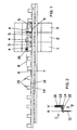
Figur 1- eine Draufsicht auf eine aus mehreren Schaltgeräten gebildete elektrische Installationsanordnung mit daran angeordneten erfindungsgemäßen Stromsammelschienen,
Figur 2- eine Schnittdarstellung durch eine der in
Figur 1 dargestellten Stromsammelschienen, Figur 3- eine Ansicht entsprechend dem Pfeil C aus
Figur 2 und Figur 4- eine Ansicht einer Stromsammelschiene entsprechend dem Pfeil D aus
Figur 2.
- FIG. 1
- a plan view of an electrical installation arrangement formed from a plurality of switching devices with arranged thereon current busbars according to the invention,
- FIG. 2
- a sectional view through one of the current busbars shown in Figure 1,
- FIG. 3
- a view corresponding to the arrow C of Figure 2 and
- FIG. 4
- a view of a busbar according to the arrow D of Figure 2.
In der Figur 1 sind schematisch drei modulare Schaltgeräte 1, 2, 3 einer elektrischen Installationsverteilung dargestellt. Die Schaltgeräte sind auf einer hier nicht näher dargestellten Befestigungsschiene festgelegt, wobei in der Regel eine Vielzahl von Schaltgeräten, auf deren Darstellung hier ebenfalls aus Gründen der Übersichtlichkeit verzichtet wurde, nebeneinander angeordnet sind.FIG. 1 schematically shows three
Im dargestellten Ausführungsbeispiel besitzt jedes Schaltgerät 1, 2, 3 an seiner dem Betrachter zugewandten Oberseite jeweils zwei mit Ausnehmungen versehene Anschlussklemmen 4 und 5. Diese Ausnehmungen sind zur Aufnahme von Anschlusslaschen von Stromschienen vorgesehen. Die Anschlussklemmen 4 liegen dabei auf einer gemeinsamen strichpunktiert dargestellten Linie 8 und werden durch eine Stromsammelschiene 6 gemeinsam mit Strom beaufschlagt. Die Anschlussklemmen 5 der Schaltgeräte 1, 2, 3 befinden sich ebenfalls auf einer gemeinsamen strichpunktiert dargestellten Linie 9 und werden von einer Sammelschiene 7 mit Strom beaufschlagt.In the illustrated embodiment, each
In der Querschnittsdarstellung der Figur 2 wird der Aufbau der in Figur 1 dargestellten Stromsammelschienen 6 und 7 im Einzelnen verdeutlicht,. Die Stromsammelschienen 6, 7 werden im Wesentlichen gebildet aus einem flachbandförmigen Längsträger 10, welcher die so genannte Verbindungsebene V der Stromsammelschiene bildet. Aus dem Längsträger 10 stehen einzelne neben einander angeordnete Anschlusslaschen 11 hervor, welche mit dem Längsträger 10 durch Verbindungsstege 12 verbunden sind. Durch die neben einander liegenden Anschlusslaschen 11 wird eine so genannte Anschlussebene A gebildet, wobei Anschlussebene A und Verbindungsebene V erfindungsgemäß parallel beabstandet zueinander angeordnet sind. Durch diese neuartige Ausbildung der Stromsammelschiene bleibt der Anschlussbereich unmittelbar oberhalb der Anschlussklemmen 4, 5 der Schaltgeräte 1, 2, 3 im Gegensatz zu aus dem Stand der Technik bekannten Stromsammelschienen frei zugänglich, so dass hier gegebenenfalls eine notwendige Anschlussverdrahtung in einer der Anschlussklemmen 4, 5 problemlos vorgenommen werden kann.In the cross-sectional view of Figure 2, the structure of the
Wie aus der Figur 2 ersichtlich ist, sind die Verbindungsstege 12 jeweils rechtwinklig sowohl zur Anschlusslasche 11 als auch zum Längsträger 10 abgewinkelt, so dass sich eine doppel-L-förmige Querschnittsgestaltung der Stromsammelschienen 6, 7 ergibt. Natürlich ist alternativ zu der rechtwinkeligen Abwinkelung auch eine Abwinkelung mit anderen Winkelgraden denkbar, erfindungswesentlich ist, dass die Anschlussebene A und die Verbindungsebene V parallel beabstandet zueinander angeordnet sind.As can be seen from Figure 2, the connecting
Aus der Figur 2 ist darüber hinaus ersichtlich, dass der Längsträger 10 von einer isolierenden Hülle 13 umschlossen ist, wobei sich an die isolierende Hülle 13 im Bereich der jeweiligen Verbindungsstege 12 Abdeckhauben 14 anschließen, die den Verbindungssteg 12 an seiner den Anschlusslaschen 11 abgewandten Oberseite überdecken. Diese Gestaltung dient dem Isolierschutz gemäss der internationalen Klassifikation IP 20, da nach Einsetzen der Stromsammelschienen 6, 7 mit ihren jeweiligen Anschlusslaschen 11 in die Anschlussklemmen 4, 5 der Schaltgeräte 1, 2 3 keine Möglichkeit mehr besteht, Strom führende Teile der Stormsammelschiene mit dem Finger zu berühren. Die Abdeckhauben 14 der Verbindungsstege 12 sowie die isolierende Hülle 13 des Längsträgers 10 werden vorteilhaft einstückig im Rahmen eines Spritzgussverfahrens hergestellt und können dabei für unterschiedliche Stromschienenanwendungen unterschiedliche farbliche Gestaltung aufweisen.It is also apparent from FIG. 2 that the
Sowohl aus der Darstellung der Figur 1 als auch aus der Darstellung der Figur 4 wird ergänzend deutlich, dass die jeweiligen Abdeckhauben 14 der Verbindungsstege 12 an ihrer vorderen, dem Längsträger 10 abgewandten Seite Ausnehmungen 15 aufweisen. Die Ausnehmungen 15 sind leicht bogenförmig ausgeführt und erleichtern die Anlage eines Anschlussdrahtes 16, der zur Stromversorgung der Stromsammelschiene 6 beispielhaft in der Figur 1 in der Anschlussklemme 4 des Schaltgerätes 1 zusätzlich eingeklemmt ist.Both from the representation of Figure 1 and from the illustration of Figure 4 is additionally clear that the respective covers 14 of the connecting
Aus der Figur 3 wird ergänzend deutlich, dass die den Längsträger umgebende Hülle 13 an ihrem unteren den Anschlusslaschen 11 zugewandtem Ende jeweils zwischen zwei benachbarten Anschlusslaschen 11 eine im Wesentlichen rechteckförmig ausgebildete Einbuchtung 17 aufweist. Bei dicht nebeneinander angeordneten Stromsammelschienen ist auf Grund dieser konstruktiven Gestaltung die Möglichkeit gegeben, dass, wie dieses insbesondere in Figur 1 deutlich wird, die Verbindungsstege 12 mit der sie überdeckenden Abdeckhaube 14 in die Einbuchtungen 17 der benachbarten Stromsammelschiene eingreifen können. Der Abstand zweier benachbarter Stromsammelschienen 6 und 7 lässt sich somit problemlos unterschiedlichen seitlichen Abständen der Anschlussklemmen 4, 5 der Schaltgeräte 1, 2, 3 anpassen. Mit Hilfe der erfindungsgemäßen Stromsammelschienen lassen sich Abstände zwischen den durch die Anschlussklemmen 4 und 5 definierten Linien 8 und 9 von 4 bis 11 mm ausgleichen.From the figure 3 is additionally clear that the surrounding the
- 11
- Schaltgerätswitchgear
- 22
- Schaltgerätswitchgear
- 33
- Schaltgerätswitchgear
- 44
- Anschlussklemmeterminal
- 55
- Anschlussklemmeterminal
- 66
- StromsammelschieneBusbar
- 7.7th
- StromsammelschieneBusbar
- 8.8th.
- Linieline
- 9.9th
- Linieline
- 10.10th
- Längsträgerlongitudinal beams
- 11.11th
- Anschlusslascheconnection tab
- 12.12th
- Verbindungsstegconnecting web
- 13.13th
- Hülleshell
- 14.14th
- Abdeckhaubecover
- 15.15th
- Ausnehmungrecess
- 16.16th
- AnschlussdrahtLead wire
- 17.17th
- Einbuchtungindentation
Claims (10)
dadurch gekennzeichnet, dass
die durch den Längsträger (10) gebildete Verbindungsebene (V) der Stromsammelschiene (6, 7) und die durch die Anschlusslaschen (11) gemeinsam gebildete Anschlussebene (A) der Stromsammelschienen (6, 7) voneinander getrennt parallel beabstandet zueinander angeordnet sind, wobei die Anschlusslaschen (11) durch Verbindungsstege (12) mit dem Längsträger (10) verbunden sind.Power bus for simultaneous phased feeding multiple juxtaposed modular switchgear in an electrical installation distribution with a flat band-shaped side rail on which one side of the joint formed by the longitudinal member connecting plane juxtaposed connecting tabs for connection with recesses in the electrical devices terminal connection protruding elements, wherein the side members of an insulating sheath is enclosed,
characterized in that
the connection plane (V) of the busbar (6, 7) formed by the longitudinal member (10) and the connection plane (A) of the busbars (6, 7) jointly formed by the connecting tabs (11) are arranged at a distance from one another parallel to one another; Connecting straps (11) are connected by connecting webs (12) with the longitudinal carrier (10).
dadurch gekennzeichnet, dass
die Verbindungsstege (12) im Wesentlichen rechtwinklig zur Anschlussebene (A) und zur Verbindungsebene (V) angeordnet sind.Busbar according to claim 1,
characterized in that
the connecting webs (12) are arranged essentially at right angles to the connecting plane (A) and to the connecting plane (V).
dadurch gekennzeichnet, dass
die Verbindungsstege (12) mindestens an ihrer den Anschlusslaschen (11) abgewandten Oberseite durch eine isolierende Abdeckhaube (14) überdeckt sind.Power busbar according to claim 1 or 2,
characterized in that
the connecting webs (12) are covered by an insulating covering hood (14) at least at their upper side facing away from the connecting straps (11).
dadurch gekennzeichnet, dass
die Abdeckhaube (14) an ihrem dem Längsträger (10) abgewandten Ende im Bereich des Austritts der jeweiligen Anschlusslasche (11) eine Ausnehmung (4, 5) aufweist.Busbar according to claim 3,
characterized in that
the covering hood (14) has a recess (4, 5) at its end facing away from the longitudinal member (10) in the region of the outlet of the respective connecting lug (11).
dadurch gekennzeichnet, dass
die Ausnehmung (15) bogenförmig ausgebildet ist.Busbar according to claim 4,
characterized in that
the recess (15) is arcuate.
dadurch gekennzeichnet, dass
die Verbindungsstege (12) eine Länge im Bereich von 4 bis 12 mm aufweisen.Busbar according to one of the preceding claims,
characterized in that
the connecting webs (12) have a length in the range of 4 to 12 mm.
dadurch gekennzeichnet, dass
an einem Längsträger (10) dreizehn Anschlusslaschen (11) angeordnet sind.Busbar according to one of the preceding claims,
characterized in that
Thirteen connecting lugs (11) are arranged on a side member (10).
dadurch gekennzeichnet, dass
an einem Längsträger (10) ein Mehrfaches von jeweils dreizehn Anschlusslaschen (11) angeordnet ist.Busbar according to one of the preceding claims,
characterized in that
a multiple of in each case thirteen connecting lugs (11) is arranged on a side member (10).
dadurch gekennzeichnet, dass
an dem Ende des Längsträgers (10) jeweils Abdeckkappen angeordnet sind.Busbar according to one of the preceding claims,
characterized in that
Cover caps are arranged at the end of the longitudinal member (10).
dadurch gekennzeichnet, dass
die Abdeckhaube (14) und die isolierende Hülle einstückig aus Kunststoffmaterial gefertigt sind, wobei unterschiedliche Farbgebungen des Kunststoffmaterials vorgesehen sind.Busbar according to one of the preceding claims,
characterized in that
the cover (14) and the insulating sheath are made in one piece from plastic material, wherein different colors of the plastic material are provided.
Applications Claiming Priority (1)
| Application Number | Priority Date | Filing Date | Title |
|---|---|---|---|
| DE200520000144 DE202005000144U1 (en) | 2005-01-06 | 2005-01-06 | Busbar |
Publications (2)
| Publication Number | Publication Date |
|---|---|
| EP1679775A1 true EP1679775A1 (en) | 2006-07-12 |
| EP1679775B1 EP1679775B1 (en) | 2012-08-15 |
Family
ID=34353818
Family Applications (1)
| Application Number | Title | Priority Date | Filing Date |
|---|---|---|---|
| EP20050027992 Not-in-force EP1679775B1 (en) | 2005-01-06 | 2005-12-21 | Busbar |
Country Status (2)
| Country | Link |
|---|---|
| EP (1) | EP1679775B1 (en) |
| DE (1) | DE202005000144U1 (en) |
Families Citing this family (2)
| Publication number | Priority date | Publication date | Assignee | Title |
|---|---|---|---|---|
| FR2935846B1 (en) * | 2008-09-10 | 2014-09-12 | Legrand France | ELECTRICAL CONNECTION COMB |
| DE202009006714U1 (en) | 2009-05-08 | 2009-07-30 | Deutsche Kahneisen Gesellschaft Mbh | Mounting plate, in particular for anchor channels |
Citations (4)
| Publication number | Priority date | Publication date | Assignee | Title |
|---|---|---|---|---|
| FR2664755A1 (en) * | 1990-07-16 | 1992-01-17 | Schrack Components Ag | System for connecting rails |
| DE19721501A1 (en) * | 1996-05-24 | 1997-12-11 | Legrand S A Limoges | Connector for forming transverse connection between two aligned modular electrical devices |
| EP1137035A1 (en) * | 2000-03-20 | 2001-09-26 | Schneider Electric Industries SA | Electrical connecting system for multiple modular electrical devices |
| DE10105597A1 (en) * | 2001-02-06 | 2002-08-08 | Elkutec Gmbh | Busbar block e.g. for electrical switchgear, includes insulated section with outer wall enclosing all busbars |
-
2005
- 2005-01-06 DE DE200520000144 patent/DE202005000144U1/en not_active Expired - Lifetime
- 2005-12-21 EP EP20050027992 patent/EP1679775B1/en not_active Not-in-force
Patent Citations (4)
| Publication number | Priority date | Publication date | Assignee | Title |
|---|---|---|---|---|
| FR2664755A1 (en) * | 1990-07-16 | 1992-01-17 | Schrack Components Ag | System for connecting rails |
| DE19721501A1 (en) * | 1996-05-24 | 1997-12-11 | Legrand S A Limoges | Connector for forming transverse connection between two aligned modular electrical devices |
| EP1137035A1 (en) * | 2000-03-20 | 2001-09-26 | Schneider Electric Industries SA | Electrical connecting system for multiple modular electrical devices |
| DE10105597A1 (en) * | 2001-02-06 | 2002-08-08 | Elkutec Gmbh | Busbar block e.g. for electrical switchgear, includes insulated section with outer wall enclosing all busbars |
Also Published As
| Publication number | Publication date |
|---|---|
| DE202005000144U1 (en) | 2005-03-17 |
| EP1679775B1 (en) | 2012-08-15 |
Similar Documents
| Publication | Publication Date | Title |
|---|---|---|
| DE2316521C3 (en) | Electrical connector for cable harnesses | |
| DE102004030085B4 (en) | Terminal for connecting electrical conductors and terminal arrangement | |
| EP1710884A1 (en) | Laminated two- or multi-phase busbar assembly | |
| EP4224635A1 (en) | Conductor connection terminal | |
| DE3621268A1 (en) | INSULATING GAS SWITCHING DEVICE | |
| EP0639877B1 (en) | Device for supplying at least one electric installation appliance with electric energy | |
| EP3132502A1 (en) | Terminal block | |
| DE102009030645B4 (en) | Brückerelement and set of at least one clamping element and Brückerelement | |
| WO2005096478A1 (en) | Long stator comprising a ground conductor and maglev railway that is equipped with said stator | |
| DE10003266A1 (en) | Circuit breaker e.g. for electrical vehicle, has variable distance between terminals, and plug movable in application/release device so plug side terminals are freely applied to or released from terminals on main body side | |
| EP1331693B1 (en) | Terminal block | |
| DE2251020C3 (en) | Connection device | |
| EP1679775B1 (en) | Busbar | |
| EP0466043B1 (en) | Distribution installation with at least two rows of electrical apparatus of a narrow type | |
| CH646281A5 (en) | GAS-ENCLOSED, PRESSURE-GAS INSULATED SWITCHGEAR. | |
| DE19530947C2 (en) | Terminal block for electricity meters | |
| EP3101745B1 (en) | Multiphase busbar with improved creepage distance | |
| DE3633854A1 (en) | SCREW TERMINAL | |
| WO1995029520A1 (en) | Busbar and cross connection for a series terminal | |
| DE102008056482B4 (en) | Busbar system with a connecting element | |
| EP4042526A1 (en) | Bus bar for lights or electrical units | |
| DE102011001152A1 (en) | Contact element e.g. spring for terminal e.g. separation clamp, has several lamellar contact blades that are formed at end portions of main portion, and contact regions formed between respective end portions and center portion | |
| DE102017112978B4 (en) | Cross connector and cross connector assembly | |
| EP0794592A2 (en) | Comb-shaped dispenser with connecting terminal | |
| CH658945A5 (en) | BUSBAR ARRANGEMENT FOR CONNECTING ADDABLE INSTALLATION DEVICES. |
Legal Events
| Date | Code | Title | Description |
|---|---|---|---|
| PUAI | Public reference made under article 153(3) epc to a published international application that has entered the european phase |
Free format text: ORIGINAL CODE: 0009012 |
|
| AK | Designated contracting states |
Kind code of ref document: A1 Designated state(s): AT BE BG CH CY CZ DE DK EE ES FI FR GB GR HU IE IS IT LI LT LU LV MC NL PL PT RO SE SI SK TR |
|
| AX | Request for extension of the european patent |
Extension state: AL BA HR MK YU |
|
| AKX | Designation fees paid | ||
| 17P | Request for examination filed |
Effective date: 20070427 |
|
| RBV | Designated contracting states (corrected) |
Designated state(s): AT BE BG CH CY CZ DE DK EE ES FI FR GB GR HU IE IS IT LI LT LU LV MC NL PL PT RO SE SI SK TR |
|
| 17Q | First examination report despatched |
Effective date: 20070614 |
|
| GRAC | Information related to communication of intention to grant a patent modified |
Free format text: ORIGINAL CODE: EPIDOSCIGR1 |
|
| GRAP | Despatch of communication of intention to grant a patent |
Free format text: ORIGINAL CODE: EPIDOSNIGR1 |
|
| GRAS | Grant fee paid |
Free format text: ORIGINAL CODE: EPIDOSNIGR3 |
|
| GRAA | (expected) grant |
Free format text: ORIGINAL CODE: 0009210 |
|
| AK | Designated contracting states |
Kind code of ref document: B1 Designated state(s): AT BE BG CH CY CZ DE DK EE ES FI FR GB GR HU IE IS IT LI LT LU LV MC NL PL PT RO SE SI SK TR |
|
| REG | Reference to a national code |
Ref country code: GB Ref legal event code: FG4D Free format text: NOT ENGLISH Ref country code: CH Ref legal event code: EP Ref country code: AT Ref legal event code: REF Ref document number: 571247 Country of ref document: AT Kind code of ref document: T Effective date: 20120815 |
|
| REG | Reference to a national code |
Ref country code: IE Ref legal event code: FG4D Free format text: LANGUAGE OF EP DOCUMENT: GERMAN |
|
| REG | Reference to a national code |
Ref country code: DE Ref legal event code: R096 Ref document number: 502005013002 Country of ref document: DE Effective date: 20121011 |
|
| REG | Reference to a national code |
Ref country code: NL Ref legal event code: VDEP Effective date: 20120815 |
|
| PG25 | Lapsed in a contracting state [announced via postgrant information from national office to epo] |
Ref country code: LT Free format text: LAPSE BECAUSE OF FAILURE TO SUBMIT A TRANSLATION OF THE DESCRIPTION OR TO PAY THE FEE WITHIN THE PRESCRIBED TIME-LIMIT Effective date: 20120815 Ref country code: CY Free format text: LAPSE BECAUSE OF FAILURE TO SUBMIT A TRANSLATION OF THE DESCRIPTION OR TO PAY THE FEE WITHIN THE PRESCRIBED TIME-LIMIT Effective date: 20120815 Ref country code: IS Free format text: LAPSE BECAUSE OF FAILURE TO SUBMIT A TRANSLATION OF THE DESCRIPTION OR TO PAY THE FEE WITHIN THE PRESCRIBED TIME-LIMIT Effective date: 20121215 Ref country code: FI Free format text: LAPSE BECAUSE OF FAILURE TO SUBMIT A TRANSLATION OF THE DESCRIPTION OR TO PAY THE FEE WITHIN THE PRESCRIBED TIME-LIMIT Effective date: 20120815 |
|
| PG25 | Lapsed in a contracting state [announced via postgrant information from national office to epo] |
Ref country code: PL Free format text: LAPSE BECAUSE OF FAILURE TO SUBMIT A TRANSLATION OF THE DESCRIPTION OR TO PAY THE FEE WITHIN THE PRESCRIBED TIME-LIMIT Effective date: 20120815 Ref country code: SI Free format text: LAPSE BECAUSE OF FAILURE TO SUBMIT A TRANSLATION OF THE DESCRIPTION OR TO PAY THE FEE WITHIN THE PRESCRIBED TIME-LIMIT Effective date: 20120815 Ref country code: LV Free format text: LAPSE BECAUSE OF FAILURE TO SUBMIT A TRANSLATION OF THE DESCRIPTION OR TO PAY THE FEE WITHIN THE PRESCRIBED TIME-LIMIT Effective date: 20120815 Ref country code: GR Free format text: LAPSE BECAUSE OF FAILURE TO SUBMIT A TRANSLATION OF THE DESCRIPTION OR TO PAY THE FEE WITHIN THE PRESCRIBED TIME-LIMIT Effective date: 20121116 Ref country code: PT Free format text: LAPSE BECAUSE OF FAILURE TO SUBMIT A TRANSLATION OF THE DESCRIPTION OR TO PAY THE FEE WITHIN THE PRESCRIBED TIME-LIMIT Effective date: 20121217 Ref country code: SE Free format text: LAPSE BECAUSE OF FAILURE TO SUBMIT A TRANSLATION OF THE DESCRIPTION OR TO PAY THE FEE WITHIN THE PRESCRIBED TIME-LIMIT Effective date: 20120815 |
|
| PG25 | Lapsed in a contracting state [announced via postgrant information from national office to epo] |
Ref country code: NL Free format text: LAPSE BECAUSE OF FAILURE TO SUBMIT A TRANSLATION OF THE DESCRIPTION OR TO PAY THE FEE WITHIN THE PRESCRIBED TIME-LIMIT Effective date: 20120815 |
|
| PG25 | Lapsed in a contracting state [announced via postgrant information from national office to epo] |
Ref country code: CZ Free format text: LAPSE BECAUSE OF FAILURE TO SUBMIT A TRANSLATION OF THE DESCRIPTION OR TO PAY THE FEE WITHIN THE PRESCRIBED TIME-LIMIT Effective date: 20120815 Ref country code: DK Free format text: LAPSE BECAUSE OF FAILURE TO SUBMIT A TRANSLATION OF THE DESCRIPTION OR TO PAY THE FEE WITHIN THE PRESCRIBED TIME-LIMIT Effective date: 20120815 Ref country code: RO Free format text: LAPSE BECAUSE OF FAILURE TO SUBMIT A TRANSLATION OF THE DESCRIPTION OR TO PAY THE FEE WITHIN THE PRESCRIBED TIME-LIMIT Effective date: 20120815 Ref country code: ES Free format text: LAPSE BECAUSE OF FAILURE TO SUBMIT A TRANSLATION OF THE DESCRIPTION OR TO PAY THE FEE WITHIN THE PRESCRIBED TIME-LIMIT Effective date: 20121126 Ref country code: EE Free format text: LAPSE BECAUSE OF FAILURE TO SUBMIT A TRANSLATION OF THE DESCRIPTION OR TO PAY THE FEE WITHIN THE PRESCRIBED TIME-LIMIT Effective date: 20120815 |
|
| PG25 | Lapsed in a contracting state [announced via postgrant information from national office to epo] |
Ref country code: IT Free format text: LAPSE BECAUSE OF FAILURE TO SUBMIT A TRANSLATION OF THE DESCRIPTION OR TO PAY THE FEE WITHIN THE PRESCRIBED TIME-LIMIT Effective date: 20120815 Ref country code: SK Free format text: LAPSE BECAUSE OF FAILURE TO SUBMIT A TRANSLATION OF THE DESCRIPTION OR TO PAY THE FEE WITHIN THE PRESCRIBED TIME-LIMIT Effective date: 20120815 |
|
| PLBE | No opposition filed within time limit |
Free format text: ORIGINAL CODE: 0009261 |
|
| STAA | Information on the status of an ep patent application or granted ep patent |
Free format text: STATUS: NO OPPOSITION FILED WITHIN TIME LIMIT |
|
| BERE | Be: lapsed |
Owner name: ELKUTEC G.M.B.H. Effective date: 20121231 |
|
| 26N | No opposition filed |
Effective date: 20130516 |
|
| PG25 | Lapsed in a contracting state [announced via postgrant information from national office to epo] |
Ref country code: MC Free format text: LAPSE BECAUSE OF NON-PAYMENT OF DUE FEES Effective date: 20121231 Ref country code: BG Free format text: LAPSE BECAUSE OF FAILURE TO SUBMIT A TRANSLATION OF THE DESCRIPTION OR TO PAY THE FEE WITHIN THE PRESCRIBED TIME-LIMIT Effective date: 20121115 |
|
| REG | Reference to a national code |
Ref country code: CH Ref legal event code: PL |
|
| GBPC | Gb: european patent ceased through non-payment of renewal fee |
Effective date: 20121221 |
|
| REG | Reference to a national code |
Ref country code: DE Ref legal event code: R097 Ref document number: 502005013002 Country of ref document: DE Effective date: 20130516 |
|
| REG | Reference to a national code |
Ref country code: IE Ref legal event code: MM4A |
|
| REG | Reference to a national code |
Ref country code: FR Ref legal event code: ST Effective date: 20130830 |
|
| PG25 | Lapsed in a contracting state [announced via postgrant information from national office to epo] |
Ref country code: BE Free format text: LAPSE BECAUSE OF NON-PAYMENT OF DUE FEES Effective date: 20121231 |
|
| REG | Reference to a national code |
Ref country code: DE Ref legal event code: R119 Ref document number: 502005013002 Country of ref document: DE Effective date: 20130702 |
|
| PG25 | Lapsed in a contracting state [announced via postgrant information from national office to epo] |
Ref country code: LI Free format text: LAPSE BECAUSE OF NON-PAYMENT OF DUE FEES Effective date: 20121231 Ref country code: DE Free format text: LAPSE BECAUSE OF NON-PAYMENT OF DUE FEES Effective date: 20130702 Ref country code: CH Free format text: LAPSE BECAUSE OF NON-PAYMENT OF DUE FEES Effective date: 20121231 Ref country code: IE Free format text: LAPSE BECAUSE OF NON-PAYMENT OF DUE FEES Effective date: 20121221 |
|
| PG25 | Lapsed in a contracting state [announced via postgrant information from national office to epo] |
Ref country code: FR Free format text: LAPSE BECAUSE OF NON-PAYMENT OF DUE FEES Effective date: 20130102 Ref country code: GB Free format text: LAPSE BECAUSE OF NON-PAYMENT OF DUE FEES Effective date: 20121221 |
|
| REG | Reference to a national code |
Ref country code: AT Ref legal event code: MM01 Ref document number: 571247 Country of ref document: AT Kind code of ref document: T Effective date: 20121221 |
|
| PG25 | Lapsed in a contracting state [announced via postgrant information from national office to epo] |
Ref country code: TR Free format text: LAPSE BECAUSE OF FAILURE TO SUBMIT A TRANSLATION OF THE DESCRIPTION OR TO PAY THE FEE WITHIN THE PRESCRIBED TIME-LIMIT Effective date: 20120815 |
|
| PG25 | Lapsed in a contracting state [announced via postgrant information from national office to epo] |
Ref country code: LU Free format text: LAPSE BECAUSE OF NON-PAYMENT OF DUE FEES Effective date: 20121221 Ref country code: AT Free format text: LAPSE BECAUSE OF NON-PAYMENT OF DUE FEES Effective date: 20121221 |
|
| PG25 | Lapsed in a contracting state [announced via postgrant information from national office to epo] |
Ref country code: HU Free format text: LAPSE BECAUSE OF FAILURE TO SUBMIT A TRANSLATION OF THE DESCRIPTION OR TO PAY THE FEE WITHIN THE PRESCRIBED TIME-LIMIT Effective date: 20051221 |