EP1679626A1 - Design support device, design support method, design support program, and recording medium - Google Patents
Design support device, design support method, design support program, and recording medium Download PDFInfo
- Publication number
- EP1679626A1 EP1679626A1 EP03770082A EP03770082A EP1679626A1 EP 1679626 A1 EP1679626 A1 EP 1679626A1 EP 03770082 A EP03770082 A EP 03770082A EP 03770082 A EP03770082 A EP 03770082A EP 1679626 A1 EP1679626 A1 EP 1679626A1
- Authority
- EP
- European Patent Office
- Prior art keywords
- divided
- unit
- generated
- generating unit
- generating
- Prior art date
- Legal status (The legal status is an assumption and is not a legal conclusion. Google has not performed a legal analysis and makes no representation as to the accuracy of the status listed.)
- Withdrawn
Links
Images









Classifications
-
- G—PHYSICS
- G06—COMPUTING OR CALCULATING; COUNTING
- G06F—ELECTRIC DIGITAL DATA PROCESSING
- G06F30/00—Computer-aided design [CAD]
- G06F30/30—Circuit design
- G06F30/32—Circuit design at the digital level
- G06F30/327—Logic synthesis; Behaviour synthesis, e.g. mapping logic, HDL to netlist, high-level language to RTL or netlist
-
- G—PHYSICS
- G06—COMPUTING OR CALCULATING; COUNTING
- G06F—ELECTRIC DIGITAL DATA PROCESSING
- G06F30/00—Computer-aided design [CAD]
-
- G—PHYSICS
- G06—COMPUTING OR CALCULATING; COUNTING
- G06F—ELECTRIC DIGITAL DATA PROCESSING
- G06F30/00—Computer-aided design [CAD]
- G06F30/30—Circuit design
Definitions
- the present invention relates to a design support apparatus, a design support method, a design support program, and a recording medium that records the program for supporting design of a design object such as large-scale integration (LSI).
- LSI large-scale integration
- the LSI design is gradually shifted from a register transfer level (RTL) to a higher operation level, and, as is the case with software design, the LSI design is generally divided and performed in several phases, such as an analysis phase, a design phase, and an install phase.
- RTL register transfer level
- the design target system is handled like a black box and a requirement analysis is performed without considering implementation. Since the analysis in the analysis phase is performed focusing on "what is produced", a data object processed by the design target system and the operation and attribute associated with each data object form basic components of the design target system.
- a designer can perform the modeling of the processing flow of the data object to analyze the event flow of the design target system.
- a final result of the analysis phase is referred to as "requested specification description" here.
- design phase division into parallel and concurrent function modules is performed by the designer in accordance with the requested specification description.
- a patent document 1 discloses a designing method for dividing a logic circuit constituting LSI into a plurality of modules to perform hierarchical design.
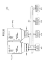
- Fig. 20 is a block diagram of a hardware configuration of a conventional design target system.
- a design target system 2000 includes, for example, a processor 2001, a main memory 2002 such as a random access memory (RAM), other peripheral hardware modules 2011 to 2014, and a bus 2003 connecting these components, which realize various complicated functions in the design target system 2000.
- main memory 2002 such as a random access memory (RAM)
- RAM random access memory
- mapping is performed at the discretion of the designer to the function modules, which are meaningful function units.
- This mapping generally forms a configuration such that, for example, encrypted data, JPEC coder-decoder (CODEC) data, moving picture experts group (MPEG) CODEC data, or other processed data are stored in the main memory 2002 connected to the bus 2003 to start processing of the next module.
- CODEC JPEC coder-decoder
- MPEG moving picture experts group
- a software function Func_SW() is mapped to the processor 2001 shown in Fig. 20 and the software function Func_SW() is assumed to include sub-functions f1(), f2(), f3().
- a hardware function Func_HW1() is mapped to the hardware Module2011 and the hardware function Func_HW1() is assumed to include sub-functions g1(), g2(), g3().
- the hardware function Func_HW1() utilizes the sub-function f3() of the software function Func_SW(). Specifically, the sub-function f3() of the software function Func_SW() reads data written by the sub-function g1() of the hardware function Func_HW1() to perform desired processing.
- Fig. 21 is a block diagram of another example of the hardware configuration of the conventional design target system shown in Fig. 20. The same symbols are added to the same components as the configuration shown in Fig. 20, and description thereof is omitted.
- the design target system 2000 includes a local memory 2004 connected to the hardware Module2011.
- the sub-function f3() of the software function Func_SW() shown in Fig. 20 is mapped to the hardware Module2011.
- the data do not have to be transferred via the main memory 2002 and the bus 2003, and the data can be transferred between the hardware Module2011 and the local memory 2004.
- Patent Document 1 Japanese Patent Application Laid-Open Publication No. 2003-016125
- the final performance requirement of the design target system 2000 may not satisfy demand of customers in a footprint or power consumption, thereby causing a problem in which the credibility and quality of the LSI design is degraded.
- a design support apparatus, a design support method, a design support program, and a recording medium that records the program includes a specification description input unit that inputs specification description describing a plurality of pieces of processing information representing a content of processing performed by a design object and association information representing associations among the processing information; a node generating unit that generates a node for each of the processing information input by the specification description input unit; a link generating unit that generates a link coupling a plurality of the nodes generated by the node generating unit based on the association information input by the specification description input unit; a divided chart generating unit that generates a plurality of divided charts by dividing a chart schematically indicating the specification description based on the nodes generated by the node generating unit and the links generated by the link generating unit; and a function-module generating unit that generates a function module executing a function based on the processing information corresponding to the nodes and the association information corresponding to the links in each
- the module division of the design object described by the specification description can be substituted by the chart division and the module division can be automated.
- the design support apparatus may set costs indicating weights of links generated by the link generating unit based on the specification description input by the specification description input unit, and may extract a link with the minimum cost set by the cost setting unit.
- the divided charts may be created based on the extracted link.
- the module division can be achieved in consideration of the overhead between the modules. Furthermore, the design support apparatus may set the cost based on common variables commonly used in the processing of the processing information corresponding to a pair of the nodes coupled by the link. The design support apparatus may calculate the number of times of execution of the processing information described in the specification description, and based on the calculated number of times of execution of the processing information, the design support apparatus may calculate the cost. According to this invention, the module division can be efficiently performed in consideration of the overhead between the modules and the performance of the design object can be improved.
- the design support apparatus may input a constraint condition limiting the number of the divided charts to be generated, a constraint condition limiting the number of the nodes to be included in the divided charts to be generated, a constraint condition to include any plurality of pieces of processing information in one of the function module, or a constraint condition not to include any plurality of pieces of processing information in one of divided specification description, and determine whether the divided charts satisfy the input constraint condition.
- the design support apparatus may generate the function module for each generated divided chart based on a result of determination. According to this invention, the module division can be performed in accordance with the performance of the design object.
- the design support apparatus may notify that the division of the chart is impossible if it is determined by the constraint condition is not satisfied.
- the module division is prevented from generating the overhead between the modules.
- the design support apparatus may generate specification description for a communication path connecting a plurality of the function modules based on the generated function modules. According to this invention, the design operation can be efficiently achieved.
- Fig. 1 is a block diagram of a hardware configuration of a design support apparatus according to an embodiment of the present invention
- Fig. 2 is an explanatory diagram of an example of a specification description described in the C++ language
- Fig. 3 is an explanatory diagram of an example of the specification description with the same content as the content shown in Fig. 2 described in the unified modeling language (UML) and the object constraint language (OCL)
- Fig. 4 is a block diagram of a functional configuration of the design support apparatus according to the embodiment of the present invention
- Fig. 5 is an explanatory diagram of an example of generating nodes from the specification description
- Fig. 6 is an explanatory diagram of an example of a chart schematically represented by the nodes shown in Fig. 5 and links
- FIG. 7 is an explanatory diagram of an example (1) of setting costs for the links in the graph shown in Fig. 6;
- Fig. 8 is an explanatory diagram of an example (2) of setting costs for the links in the graph shown in Fig. 6;
- Fig. 9 is an explanatory diagram of an example (3) of setting costs for the links in the graph shown in Fig. 6;
- Fig. 10 is an explanatory diagrams of division solutions obtained from the graph shown in Fig. 8;
- Fig. 11 is an explanatory diagram of an example of generating a function module from each sub-graph of the division solution shown in Fig. 10;
- Fig. 12 is an explanatory diagram of an example of representing the same content as the content shown in Fig. 11 with the System C;
- FIG. 13 is an explanatory diagram of a specification description for a communication path generated between the function modules shown in Fig. 12;
- Fig. 14 is an explanatory diagram of an example of dividing into sub-graphs in conformity to a constraint condition;
- Fig. 15 is a flowchart of a design support processing of the design support apparatus according to the embodiment of the present invention;
- Fig. 16 is an explanatory diagram of another example of the node generation of the design support apparatus according to the embodiment of the present invention;
- Fig. 17 is a block diagram of a functional configuration of a cost setting unit in this case;
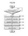
- Fig. 18 is a flowchart of an example of a cost setting processing;
- Fig. 19 is an explanatory diagram of a graph with costs set by the cost setting processing;
- Fig. 20 is a block diagram of a hardware configuration of a conventional design target system;
- Fig. 21 is a block diagram of another example of a hardware configuration of a conventional design target system.
- Fig. 1 is a block diagram of a hardware configuration of the design support apparatus according to the embodiment of the present invention.
- the design support apparatus includes a central processing unit (CPU) 101, a read-only memory (ROM) 102, a random access memory (RAM) 103, a hard disk drive (HDD) 104, a hard disk (HD) 105, a flexible disk drive (FDD) 106, a flexible disk (FD) 107 as an example of a removable recording medium, a display 108, an interface (I/F) 109, a keyboard 110, a mouse 111, a scanner 112, and a printer 113.
- the components are connected to each other through a bus 100.
- the CPU 101 is responsible for overall control of the design support apparatus.
- the ROM 102 stores programs such as a boot program.
- the RAM 103 is used for a work area of the CPU 101.
- the HDD 104 controls read/write of data from/to the HD 105 under the control of the CPU 101.
- the HD 105 stores data written under the control of the HDD 104.
- the FDD 106 controls read/write of data from/to the FD 107 under the control of the CPU 101.
- the FD 107 stores data written under the control of the FDD 106 and allows the design support apparatus to read the data stored in the FD 107.
- a compact-disc read-only memory (a compact-disc recordable (CD-R), a compact-disk rewritable (CD-RW)), a magneto optical (MO) disk, a digital versatile disk (DVD), and a memory card may be used.
- the display 108 displays a cursor, icons or tool boxes as well as data such as a document, an image, and function information.
- This display 108 may be, for example, a cathode ray tube (CRT), a thin film transistor (TFT) liquid crystal display, a plasma display, etc.
- CTR cathode ray tube
- TFT thin film transistor
- the I/F 109 is connected via a communication line to a network 114 such as the internet and is connected to other apparatuses via this network 114.
- the I/F 109 is responsible for interfacing the network 114 with the inside of the apparatus and controls input/output of data from/to an external apparatus.
- the I/F 109 may be, for example, a modem, a LAN adaptor, etc.
- the keyboard 110 is provided with keys for entering characters, numeric characters, various instructions, etc. to enter data.
- a touch-panel type input pad, a numeric keypad, etc. may be used instead.
- the mouse 111 moves a cursor, selects an area or moves and resizes a window, etc.
- a trackball or joystick may be used instead, as long as similar functions for a pointing device are provided.
- the scanner 112 reads an image optically and captures image data into the design support apparatus.
- the scanner 112 may have an OCR function.
- the printer 113 prints image data and document data.
- the printer 113 may be, for example, a laser printer or ink-jet printer.
- the specification description is an analysis result of a requirement analysis without considering implementation of a design object such as LSI, which is obtained in an analysis phase of LSI design.
- the specification description is described in a predetermined computer-recognizable language.
- the specification description describes a plurality of pieces of processing information representing content of processing performed by the design object and association information representing associations in the plurality of pieces of the processing information.
- a specific example of the specification description will be described with reference to Fig. 2 and Fig. 3.
- Fig. 2 is an explanatory diagram of an example of the specification description described in the C++ language
- Fig. 3 is an explanatory diagram of an example of the specification description with the same content as Fig. 2 described in the UML and the OCL.
- a specification description 200 shown in Fig. 2 has a main function 201 and a subroutine 202.
- sets of data objects are represented by classes (Class1 and Class2).
- the class has an attribute and operations playing a role of a plurality of pieces of the processing information.
- an integer-type (int) attribute q, operation 01, operation 02, and operation 03 exist in the Class1.
- the operations O1 to 03 constitute an object 1, which is an object of the Class1.
- an integer-type attribute m and operation 04 exist.
- the operation 04 constitutes an object 2, which is an object of the Class2.
- class instances i.e., data objects are generated and the calling orders (interactions) thereof are described.
- the Class1 and Class2 are represented using UML class diagrams 301, 302, respectively.
- the portion of the main function shown in Fig. 2 is represented using a sequence diagram 303 at the lower left of Fig. 3.
- a post condition of the operation of each class can be defined using an OCL 304, which is also the specification description language, as shown on the right of Fig. 3.
- OCL 304 which is also the specification description language
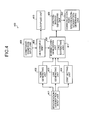
- Fig. 4 is a block diagram of a functional configuration of the design support apparatus according to the embodiment of the present invention.
- a design support apparatus 400 is configured to include a specification-description input unit 401, a node generating unit 402, a link generating unit 403, a cost setting unit 404, a divided-chart generating unit 405, a function-module generating unit 406, a communication-path specification-description generating unit 407, a constraint-condition input unit 408, a determining unit 409, and a notifying unit 410.
- the specification-description input unit 401 inputs the specification description describing a plurality of pieces of processing information representing content of processing performed by a design object such as LSI and association information representing associations in the plurality of pieces of the processing information. Specifically, the specification-description input unit 401 inputs the specification description 200 described in the C++ language shown in Fig. 2 and the specification description 300 described with the UML diagrams 301 to 303 and the OCL 304 shown in Fig. 3 as described above.
- the node generating unit 402 generates a node for each of the plurality of pieces of the processing information input by the specification-description input unit 401.
- Fig. 5 is an explanatory diagram of an example of generating nodes from the specification description.
- the node generating unit 402 extracts the operations O1 to 04 included in the Class1 and the Class2 of the class diagrams 301, 302 and converts the extracted operations 01 to 04 into nodes V1 to V4. In this way, the nodes V1 to V4 can be generated.
- the link generating unit 403 generates a link coupling a plurality of the nodes generated by the node generating unit 402, based on the association information input by the specification-description input unit 401.
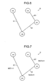
- Fig. 6 is an explanatory diagram of an example of a chart schematically represented by the nodes shown in Fig. 5 and links.
- the association information is information representing the associations in the plurality of pieces of the processing information and can be represented by the presence of the association among various parameters of the data objects shown in Figs. 2 and 3 or by the presence of the association among the operations O1 to 04 obtained from the delivery of the parameters, for example.
- the operation O1 and the operation 02 access to the common attribute q and it can be known that an association exists between the operation 01 and the operation 02.
- a return value t obtained from the operation 02 of the Class1 and a return value s obtained from the operation 03 are delivered to the operation 04 of the Class2. Therefore, it can be known that an association exists between the operation 02 and the operation 04 and, similarly, it can be known that an association exists between the operation 03 and the operation 04.
- the link generating unit 403 can generate a link E3 coupling the node V1 generated from the operation 01 and the node V2 generated from the operation 02, as shown in Fig. 6. Since the association exists between the operation 02 and the operation 04, the link generating unit 403 can generate a link E2 coupling the node V2 generated from the operation 02 and the node V4 generated from the operation 04.
- the link generating unit 403 can generate a link E1 coupling the node V3 generated from the operation 03 and the node V4 generated from the operation 04.
- a graph G is generated as an example of a chart.
- the cost setting unit 404 sets costs indicating weights of links generated by the link generating unit 403, based on the specification description input by the specification-description input unit 401.
- the cost setting unit 404 can set the cost based on a bit length of the common variable used in common in the processing between pieces of the processing information corresponding to a pair of the nodes coupled by the link.
- One parameter q is the integer type (int) and, thus, the bit length is 32 bits.
- sub-graphs i.e., a plurality of divided charts are generated by dividing the graph G, which is the chart of the specification description schematically, based on the nodes V1 to V4 generated by the node generating unit 402 and the links E1 to E3 generated by the link generating unit 403.
- the divided-chart generating unit 405 is provided with a link extracting unit 411.
- the link extracting unit 411 extracts a link with a minimum cost set by the cost setting unit 404. For example, from the graph G shown in Fig. 7, all the links E1 to E3 are extracted. From the graph G shown in Fig. 8, the links E2 and e3 are extracted. From the graph G shown in Fig. 9, the links E2 and e3 are extracted. Specifically, the extraction of the links is performed by a Min-Cut algorithm described later.
- the divided-chart generating unit 405 can generate the sub-graphs, i.e., a plurality of divided charts based on the links extracted by the link extracting unit 411. Into this division processing, the Min-Cut algorithm can be introduced.
- the Min-Cut can cut the link with the minimum weighting cost between the subsets S and T of the nodes V. In this way, a resolution can be obtained in O(2n ⁇ logn) time. n is the number of the nodes.
- Fig. 10 is an explanatory diagram of division solutions obtained from the graph shown in Fig. 8.
- the graph G shown in Fig. 8 shows an example of division of the graph when the costs of the link E1 to link E3 are set depending on the number of parameters.
- a sub-graph G1 is constituted by the node V3, the node V4, and the link E1, and a sub-graph G2 is constituted by the node V1, the node V2, and the link E3.
- a sub-graph G1 is constituted by the node V2, the node V3, the node V4, the link E1, and the link E2, and a sub-graph G2 is constituted by the node V1. Since the link coupling the sub-graphs G1 and G2 has the minimum cost, both the division solution 1 and the division solution 2 are correct answers.
- the function-module generating unit 406 generates a function module executing a function based on the processing information corresponding to the nodes and the association information corresponding to the links in each divided chart for each of a plurality of the divided charts generated by the divided-chart generating unit 405.
- Fig. 11 is an explanatory diagram of an example of generating a function module from each of the sub-graphs G1, G2 of the division solution 1 shown in Fig. 10.
- the sub-graph G1 is compiled into a function Modulel represented by a UML class diagram 1101 and the sub-graph G2 is wrapped up into a function Module2 represented by a UML class diagram 1102.
- a «module» stereotype indicates that a relevant class is a module.
- a «process» stereotype indicates that the operation of the module is a process.
- a «port» stereotype indicates a port for communication between the modules.
- the operation 03 of the Class1 and the operation 04 of the Class2 are compiled into entry () of a process «process» of the function module Modulel, since the sub-graph G1 includes the nodes V3, V4.
- the operation O1 and the operation 02 of the Class1 are compiled into entry () of a process «process» of the function module Module2, since the sub-graph G2 includes the nodes V1, V2.
- ports for communication between the function module Modulel and the function module Module2 can be determined since two parameters are communicated between the function module Module1 and the function module Module2.
- the function module Module1 is assigned with data_in1 and data_in2.
- the respective data types are represented by in ⁇ int> and in ⁇ bool>. In ⁇ type> indicates the input side.
- the function module Module2 is provided with ports of data_out1 and data_out2.
- the respective data types are represented by out ⁇ int> and out ⁇ bool>.
- Out ⁇ type> represents the output side.
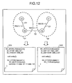
- Fig. 12 is an explanatory diagram of an example of representing the same content as Fig. 11 with System C 1201, 1202.
- an SC_MODULE() macro defines a function module.
- SC_CTOR represents a portion to be regarded as processing.
- SC_METHOD and SC_THREAD indicate processes.
- Module2 is expressed by SC_THREAD since an input port does not exist.
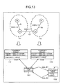
- the communication-path specification-description generating unit 407 generates the specification description for a communication path connecting a plurality of the function modules based on the plurality of function modules generated by the function-module generating unit 406.
- Fig. 13 is an explanatory diagram of the specification description for a communication path generated between the function modules shown in Fig. 12.
- the class diagram 1101 TOP
- a Class1302 (signal) can be generated which is represented by a communication path «channel» stereotype. In this way, the level of the completion of design can be enhanced.
- the constraint-condition input unit 408 inputs a constraint condition constraining the number of generation of the divided charts generated by the divided-chart generating unit 405.
- An example of the constraint condition can be the number of the divided charts equal to a predetermined number, equal to or less than a predetermined number, equal to or more than a predetermined number, or equal to or more than a predetermined number as well as equal to or less than a predetermined number, for example.
- the constraint-condition input unit 408 can input a constraint condition constraining the number of the nodes included in a plurality of the divided charts generated by the divided-chart generating unit 405.
- An example of the constraint condition can be the number of the nodes included in the divided charts equal to a predetermined number, equal to or less than a predetermined number, equal to or more than a predetermined number or more, or equal to or more than a predetermined number as well as equal to or less than a predetermined number, for example.
- the constraint-condition input unit 408 can input a constraint condition that includes content for including any plurality of pieces of processing information in one function module or content for not including any plurality of pieces of processing information in one function module.
- the constraint-condition input unit 408 can input a constraint condition for including the operation 01 and the operation 02 to the same function module or a constraint condition for not including the operation 02 and the operation 03 to the same function module.
- the determining unit 409 determines whether or not the divided charts generated by the divided-chart generating unit 405 satisfy the constraint condition input by the constraint-condition input unit 408. In this case, the divided-chart generating unit 405 divides a graph, i.e., a chart into sub-graphs, i.e., a plurality of divided charts based on the determination result determined by the determining unit 409.
- Fig. 14 is an explanatory diagram of an example of dividing into the sub-graphs in conformity to the constraint condition.
- Fig. 14 illustrates one division solution 1 of the two division solution shown in Fig. 10.
- the division solution 2 shown in Fig. 10 will be excluded and only the division solution 1 will be a correct answer.
- the notifying unit 410 notifies that the division into the divided charts is impossible. Specifically, for example, the notification is performed by displaying this content on the display 108 shown in Fig. 1.
- the link extracting unit 411 specifically, for example, the functions thereof are realized by executing programs recorded on the ROM 102, the RAM 103, the HD 105, the FD 107 etc. shown in Fig. 1 with the CPU 101 or by the I/F 109.
- Fig. 15 is a flowchart of a design support processing of the design support apparatus according to the embodiment of the present invention.
- step S1501 when the specification description 200, 300 shown in Figs. 2 and 3 is input (step S1501: YES), the nodes are generated from the processing information described in the specification description 200, 300 (step S1502). The links and the costs thereof are generated from the association information described in the specification description (step S1503, step S1504). In this way, the graph G is generated which is constituted by the nodes V and the links E.
- step S1505 The link with the minimum cost is extracted from the graph G by the Min-Cut algorithm (step S1505) and the graph G is divided by cutting the extracted link (step S1506). If the constraint condition does not exist (step S1507: NO), the sub-graphs are generated from the division solutions (step S1510). On the other hand, if the constraint condition exists (step S1507: NO), it is determined whether or not a division solution satisfying the constraint condition exists in the division solutions (step S1508). If the satisfying division solution does not exist (step S1508: NO), it is displayed that the graph G cannot be divided (step S1509).
- step S1508 YES
- the sub-graphs are output from the division solution (step S1510).
- the function modules are generated from the output sub-graphs (step S1511) and the specification description is generated for the communication path between the function modules (step S1512).
- optimum LSI design can be performed regardless of yeas of experience and a skill level of an LSI designer.
- a node V5 and a node V6 may be generated by extracting the attribute q and the attribute m included in the Class1 and the Class2 playing a role of the plurality of pieces of the processing information input into the specification-description input unit 401, as shown in Fig. 16. In this way, the division into the sub-groups can be performed in units of the attribute.
- Fig. 17 is a block diagram of a functional configuration of the cost setting unit in this case.
- the cost setting unit 404 is provided with a converting unit 1701, a profile unit 1702, an execution-count calculating unit 1703, and a cost calculating unit 1704.
- the converting unit 1701 converts the specification description input by the specification-description input unit 401 into an executable model using a program language. Specifically, the specification description 200 described in the C++ language is compiled to an executable model by a compiler such as gcc_pg.
- the profile unit 1702 profiles the executable model with a profiler such as a free command gprof.
- the execution-count calculating unit 1703 calculates the number of times of execution of the processing information (e.g., operation O1 to operation 04) represented by the nodes V.
- the cost calculating unit 1704 calculates the cost by summing the number of times of execution of the processing information represented by a pair of nodes V coupled by the link E.
- Fig. 18 is a flowchart of an example of a cost setting processing.
- the specification description 200 described in the C++ language is input (step S1801: YES)
- the input specification description 200 is compiled to the executable model by the compiler such as gcc_pg (step S1802). Since the free command gprof is used for the profiler, "-pg” is added at the time of the compiling. "-pg” is a flag for using gprof.
- the compiled executable model is executed by applying a test case (step S1803) to generate profile data (step S1804). From the generated profile data, the number of times of execution of the operation O1 to the operation 04 is calculated (step S1805). In this way, the costs W(V1) to W(V4) of the nodes V1 to V4 can be obtained.
- the cost of each link is calculated by summing the costs of a pair of nodes V coupled through each link E1 to E3 (step S 1806). The costs of the links can be set by the calculated costs.
- Fig. 19 is an explanatory diagram of a graph with the costs set by the cost setting processing.
- a cost W(E1) of the link E1 is a cost obtained by summing the cost W(V3) of the node V3 and the cost W(V4) of the node V4.
- a cost W(E2) of the link E2 is a cost obtained by summing the cost W(V2) of the node V2 and the cost W(V4) of the node V4.
- a cost W(E3) of the link E3 is a cost obtained by summing the cost W(V1) of the node V1 and the cost W(V2) of the node V2.
- the cost can be set with the emphasis on the number of times of the execution of each of the operation O1 to the operation 04 when the specification description is executed.
- the module division can be performed in consideration of a data transfer amount in the communication between modules. Therefore, each function module can be executed without generating the overhead and the performance of the design target can be improved.
- changes in the design can be reduced which are caused because the customer's request is not satisfied by the final performance requirement of the design target system, for example, a mounting footprint or power consumption, and the design quality and the credibility can be improved. This reduces the redesign and the design period can be shortened.
- the design support method described in the embodiment can be achieved by executing a program prepared in advance with a computer such as a personal computer or a workstation.
- the program is recorded on a computer-readable medium such as a hard disk, flexible disk, CD-ROM, MO, and DVD and is read from the recording medium by the computer for execution.
- the program may be a transmission medium that can be distributed through network such as the internet.
- the module division of the design object described by the specification description can be replaced with the graph division and the automation of the module division can be achieved. In this way, the design operation of the design object can be supported easily and efficiently.
- the present invention is suitable for providing a design support apparatus, a design support method, a design support program, and a recording medium that records the program for dividing the specification description described in the C++ language, UML, OSL, etc. into function modules that can be executed in parallel and concurrently.
Landscapes
- Engineering & Computer Science (AREA)
- Physics & Mathematics (AREA)
- Theoretical Computer Science (AREA)
- Computer Hardware Design (AREA)
- Evolutionary Computation (AREA)
- Geometry (AREA)
- General Engineering & Computer Science (AREA)
- General Physics & Mathematics (AREA)
- Design And Manufacture Of Integrated Circuits (AREA)
- Stored Programmes (AREA)
Abstract
Description
- The present invention relates to a design support apparatus, a design support method, a design support program, and a recording medium that records the program for supporting design of a design object such as large-scale integration (LSI).
- Recently, as a scale of LSI design becomes larger, functions of a design target system has rapidly become complicate, and the LSI realizes wide range of circuits from a conventional single-function hardware circuit to a multifunction or combined-function circuit. Therefore, the LSI design is gradually shifted from a register transfer level (RTL) to a higher operation level, and, as is the case with software design, the LSI design is generally divided and performed in several phases, such as an analysis phase, a design phase, and an install phase.
- In the analysis phase, the design target system is handled like a black box and a requirement analysis is performed without considering implementation. Since the analysis in the analysis phase is performed focusing on "what is produced", a data object processed by the design target system and the operation and attribute associated with each data object form basic components of the design target system.
- A designer can perform the modeling of the processing flow of the data object to analyze the event flow of the design target system. A final result of the analysis phase is referred to as "requested specification description" here. In the design phase, division into parallel and concurrent function modules is performed by the designer in accordance with the requested specification description.
- Since implementation is not considered in the analysis phase, the operation and attribute associated with the data is not necessarily divided into the same function modules. Such division into the function modules is performed based on long years of experience and intuition of the designer at present. For example, a
patent document 1 below discloses a designing method for dividing a logic circuit constituting LSI into a plurality of modules to perform hierarchical design. - Specific description will be made of such conventional division into function modules. Fig. 20 is a block diagram of a hardware configuration of a conventional design target system. As shown in Fig. 20, a
design target system 2000 includes, for example, aprocessor 2001, amain memory 2002 such as a random access memory (RAM), otherperipheral hardware modules 2011 to 2014, and abus 2003 connecting these components, which realize various complicated functions in thedesign target system 2000. - In the conventional division into function modules, mapping is performed at the discretion of the designer to the function modules, which are meaningful function units. This mapping generally forms a configuration such that, for example, encrypted data, JPEC coder-decoder (CODEC) data, moving picture experts group (MPEG) CODEC data, or other processed data are stored in the
main memory 2002 connected to thebus 2003 to start processing of the next module. - For example, a software function Func_SW() is mapped to the
processor 2001 shown in Fig. 20 and the software function Func_SW() is assumed to include sub-functions f1(), f2(), f3(). On the other hand, a hardware function Func_HW1() is mapped to the hardware Module2011 and the hardware function Func_HW1() is assumed to include sub-functions g1(), g2(), g3(). The hardware function Func_HW1() utilizes the sub-function f3() of the software function Func_SW(). Specifically, the sub-function f3() of the software function Func_SW() reads data written by the sub-function g1() of the hardware function Func_HW1() to perform desired processing. - In such a case, when executing the sub-function f3() of the software function Func_SW(), data are written by the sub-function g1() of the hardware function Func_HW1() from the hardware Module2011 into the
main memory 2002 through the bus. The data written into themain memory 2002 are read by theprocessor 2001 through thebus 2003. The sub-function f3() of the software function Func_SW() processes the read data and writes the data into themain memory 2002 again through thebus 2003, and the sub-function g1() of the hardware function Func_HW1() reads the data written into themain memory 2002 through thebus 2003. - The sub-function f3() of the software function Func_SW() may be preliminarily mapped. Fig. 21 is a block diagram of another example of the hardware configuration of the conventional design target system shown in Fig. 20. The same symbols are added to the same components as the configuration shown in Fig. 20, and description thereof is omitted. As shown in Fig. 21, the
design target system 2000 includes alocal memory 2004 connected to the hardware Module2011. The sub-function f3() of the software function Func_SW() shown in Fig. 20 is mapped to the hardware Module2011. Thus, when executing the sub-function f3(), the data do not have to be transferred via themain memory 2002 and thebus 2003, and the data can be transferred between the hardware Module2011 and thelocal memory 2004.
Patent Document 1
Japanese Patent Application Laid-Open Publication No. 2003-016125 - However, in the
design target system 2000 designed in accordance with the conventional module division shown in Fig. 20 described above, since going through themain memory 2002 and thebus 2003, a large amount of data must be transferred. Therefore, an enormous communication cost is generated between theprocessor 2001 and the hardware Module2011, thereby causing a problem in which overhead is generated and that the performance of thedesign target system 2000 is degraded. - In the
design target system 2000 designed in accordance with the conventional module division shown in Fig. 21, since the sub-function f3() of the software function Func_SW() is merely one of many algorithms in the software function Func_SW(), the designer cannot find out that the sub-function f3() is utilized in the processing of the sub-function g1() of the hardware function Func_HW1(). Therefore, when the module division is performed based on the experience of the designer, it is very difficult to realize the optimum mapping as shown in Fig. 21. - Since the optimum division result is not necessarily obtained by the conventional module division, the final performance requirement of the
design target system 2000 may not satisfy demand of customers in a footprint or power consumption, thereby causing a problem in which the credibility and quality of the LSI design is degraded. - In a design operation site, if some functions are frequently deleted or redesigned to prevent the degradation of the credibility and quality of the LSI design, the efficiency of the design operation is reduced and the LSI design period is prolonged.
- In view of the above problems, it is an object of the present invention to provide a design support apparatus, a design support method, a design support program, and a recording medium that records the program capable of supporting design operation for a design object easily and efficiently.
- To solve the above problems and to achieve the object, a design support apparatus, a design support method, a design support program, and a recording medium that records the program includes a specification description input unit that inputs specification description describing a plurality of pieces of processing information representing a content of processing performed by a design object and association information representing associations among the processing information; a node generating unit that generates a node for each of the processing information input by the specification description input unit; a link generating unit that generates a link coupling a plurality of the nodes generated by the node generating unit based on the association information input by the specification description input unit; a divided chart generating unit that generates a plurality of divided charts by dividing a chart schematically indicating the specification description based on the nodes generated by the node generating unit and the links generated by the link generating unit; and a function-module generating unit that generates a function module executing a function based on the processing information corresponding to the nodes and the association information corresponding to the links in each divided chart for each of a plurality of the divided charts generated by the divided chart generating unit.
- According to this invention, since the requested specification description is converted to a chart constituted by the nodes and the links, the module division of the design object described by the specification description can be substituted by the chart division and the module division can be automated.
Moreover, the design support apparatus may set costs indicating weights of links generated by the link generating unit based on the specification description input by the specification description input unit, and may extract a link with the minimum cost set by the cost setting unit. The divided charts may be created based on the extracted link. - According to this invention, the module division can be achieved in consideration of the overhead between the modules.
Furthermore, the design support apparatus may set the cost based on common variables commonly used in the processing of the processing information corresponding to a pair of the nodes coupled by the link. The design support apparatus may calculate the number of times of execution of the processing information described in the specification description, and based on the calculated number of times of execution of the processing information, the design support apparatus may calculate the cost. According to this invention, the module division can be efficiently performed in consideration of the overhead between the modules and the performance of the design object can be improved. - Moreover, the design support apparatus may input a constraint condition limiting the number of the divided charts to be generated, a constraint condition limiting the number of the nodes to be included in the divided charts to be generated, a constraint condition to include any plurality of pieces of processing information in one of the function module, or a constraint condition not to include any plurality of pieces of processing information in one of divided specification description, and determine whether the divided charts satisfy the input constraint condition. The design support apparatus may generate the function module for each generated divided chart based on a result of determination. According to this invention, the module division can be performed in accordance with the performance of the design object.
- Furthermore, the design support apparatus may notify that the division of the chart is impossible if it is determined by the constraint condition is not satisfied. According to this invention, the module division is prevented from generating the overhead between the modules.
- Moreover, the design support apparatus may generate specification description for a communication path connecting a plurality of the function modules based on the generated function modules. According to this invention, the design operation can be efficiently achieved.
- Fig. 1 is a block diagram of a hardware configuration of a design support apparatus according to an embodiment of the present invention; Fig. 2 is an explanatory diagram of an example of a specification description described in the C++ language; Fig. 3 is an explanatory diagram of an example of the specification description with the same content as the content shown in Fig. 2 described in the unified modeling language (UML) and the object constraint language (OCL); Fig. 4 is a block diagram of a functional configuration of the design support apparatus according to the embodiment of the present invention; Fig. 5 is an explanatory diagram of an example of generating nodes from the specification description; Fig. 6 is an explanatory diagram of an example of a chart schematically represented by the nodes shown in Fig. 5 and links; Fig. 7 is an explanatory diagram of an example (1) of setting costs for the links in the graph shown in Fig. 6; Fig. 8 is an explanatory diagram of an example (2) of setting costs for the links in the graph shown in Fig. 6; Fig. 9 is an explanatory diagram of an example (3) of setting costs for the links in the graph shown in Fig. 6; Fig. 10 is an explanatory diagrams of division solutions obtained from the graph shown in Fig. 8; Fig. 11 is an explanatory diagram of an example of generating a function module from each sub-graph of the division solution shown in Fig. 10; Fig. 12 is an explanatory diagram of an example of representing the same content as the content shown in Fig. 11 with the System C; Fig. 13 is an explanatory diagram of a specification description for a communication path generated between the function modules shown in Fig. 12; Fig. 14 is an explanatory diagram of an example of dividing into sub-graphs in conformity to a constraint condition; Fig. 15 is a flowchart of a design support processing of the design support apparatus according to the embodiment of the present invention; Fig. 16 is an explanatory diagram of another example of the node generation of the design support apparatus according to the embodiment of the present invention; Fig. 17 is a block diagram of a functional configuration of a cost setting unit in this case; Fig. 18 is a flowchart of an example of a cost setting processing; Fig. 19 is an explanatory diagram of a graph with costs set by the cost setting processing; Fig. 20 is a block diagram of a hardware configuration of a conventional design target system; and Fig. 21 is a block diagram of another example of a hardware configuration of a conventional design target system.
- Exemplary embodiments of a design support apparatus, a design support method, a design support program, and a recording medium that records the program according to the present invention will be explained in detail with reference to the drawings.
- Description will be made of a hardware configuration of the design support apparatus according to the embodiment of the present invention. Fig. 1 is a block diagram of a hardware configuration of the design support apparatus according to the embodiment of the present invention. As shown in Fig. 1, the design support apparatus includes a central processing unit (CPU) 101, a read-only memory (ROM) 102, a random access memory (RAM) 103, a hard disk drive (HDD) 104, a hard disk (HD) 105, a flexible disk drive (FDD) 106, a flexible disk (FD) 107 as an example of a removable recording medium, a
display 108, an interface (I/F) 109, akeyboard 110, amouse 111, ascanner 112, and aprinter 113. The components are connected to each other through abus 100. - The
CPU 101 is responsible for overall control of the design support apparatus. TheROM 102 stores programs such as a boot program. TheRAM 103 is used for a work area of theCPU 101. TheHDD 104 controls read/write of data from/to theHD 105 under the control of theCPU 101. TheHD 105 stores data written under the control of theHDD 104. - The
FDD 106 controls read/write of data from/to theFD 107 under the control of theCPU 101. TheFD 107 stores data written under the control of theFDD 106 and allows the design support apparatus to read the data stored in theFD 107. - As a removable recording medium, in addition to the
FD 107, a compact-disc read-only memory (CD-ROM) (a compact-disc recordable (CD-R), a compact-disk rewritable (CD-RW)), a magneto optical (MO) disk, a digital versatile disk (DVD), and a memory card may be used. Thedisplay 108 displays a cursor, icons or tool boxes as well as data such as a document, an image, and function information. Thisdisplay 108 may be, for example, a cathode ray tube (CRT), a thin film transistor (TFT) liquid crystal display, a plasma display, etc. - The I/
F 109 is connected via a communication line to anetwork 114 such as the internet and is connected to other apparatuses via thisnetwork 114. The I/F 109 is responsible for interfacing thenetwork 114 with the inside of the apparatus and controls input/output of data from/to an external apparatus. The I/F 109 may be, for example, a modem, a LAN adaptor, etc. - The
keyboard 110 is provided with keys for entering characters, numeric characters, various instructions, etc. to enter data. A touch-panel type input pad, a numeric keypad, etc. may be used instead. Themouse 111 moves a cursor, selects an area or moves and resizes a window, etc. A trackball or joystick may be used instead, as long as similar functions for a pointing device are provided. - The
scanner 112 reads an image optically and captures image data into the design support apparatus. Thescanner 112 may have an OCR function. Theprinter 113 prints image data and document data. Theprinter 113 may be, for example, a laser printer or ink-jet printer. - Description will be made of a specification description used in the design support apparatus according to the embodiment of the present invention. The specification description is an analysis result of a requirement analysis without considering implementation of a design object such as LSI, which is obtained in an analysis phase of LSI design. The specification description is described in a predetermined computer-recognizable language. The specification description describes a plurality of pieces of processing information representing content of processing performed by the design object and association information representing associations in the plurality of pieces of the processing information. A specific example of the specification description will be described with reference to Fig. 2 and Fig. 3. Fig. 2 is an explanatory diagram of an example of the specification description described in the C++ language and Fig. 3 is an explanatory diagram of an example of the specification description with the same content as Fig. 2 described in the UML and the OCL.
- A
specification description 200 shown in Fig. 2 has amain function 201 and asubroutine 202. In thisspecification description 200, sets of data objects are represented by classes (Class1 and Class2). The class has an attribute and operations playing a role of a plurality of pieces of the processing information. For example, in the Class1, an integer-type (int) attribute q,operation 01,operation 02, andoperation 03 exist. The operations O1 to 03 constitute anobject 1, which is an object of the Class1. In the Class2, an integer-type attribute m andoperation 04 exist. Theoperation 04 constitutes anobject 2, which is an object of the Class2. In themain function 201 shown on the right of Fig. 2, class instances, i.e., data objects are generated and the calling orders (interactions) thereof are described. - Similarly, in a
specification description 300 shown in Fig. 3, the Class1 and Class2 are represented using UML class diagrams 301, 302, respectively. The portion of the main function shown in Fig. 2 is represented using a sequence diagram 303 at the lower left of Fig. 3. However, since it is difficult to model the operation content with the UML diagrams 301 to 303, a post condition of the operation of each class can be defined using anOCL 304, which is also the specification description language, as shown on the right of Fig. 3. A specific example of the association information representing the associations in the plurality of pieces of the processing information will be described later. - Description will be made of a functional configuration of the design support apparatus according to the embodiment of the present invention. Fig. 4 is a block diagram of a functional configuration of the design support apparatus according to the embodiment of the present invention. As shown in Fig. 4, a
design support apparatus 400 is configured to include a specification-description input unit 401, anode generating unit 402, alink generating unit 403, acost setting unit 404, a divided-chart generating unit 405, a function-module generating unit 406, a communication-path specification-description generating unit 407, a constraint-condition input unit 408, a determiningunit 409, and a notifyingunit 410. - The specification-
description input unit 401 inputs the specification description describing a plurality of pieces of processing information representing content of processing performed by a design object such as LSI and association information representing associations in the plurality of pieces of the processing information. Specifically, the specification-description input unit 401 inputs thespecification description 200 described in the C++ language shown in Fig. 2 and thespecification description 300 described with the UML diagrams 301 to 303 and theOCL 304 shown in Fig. 3 as described above. - The
node generating unit 402 generates a node for each of the plurality of pieces of the processing information input by the specification-description input unit 401. Fig. 5 is an explanatory diagram of an example of generating nodes from the specification description. In Fig. 5, thenode generating unit 402 extracts the operations O1 to 04 included in the Class1 and the Class2 of the class diagrams 301, 302 and converts the extractedoperations 01 to 04 into nodes V1 to V4. In this way, the nodes V1 to V4 can be generated. - The
link generating unit 403 generates a link coupling a plurality of the nodes generated by thenode generating unit 402, based on the association information input by the specification-description input unit 401. Fig. 6 is an explanatory diagram of an example of a chart schematically represented by the nodes shown in Fig. 5 and links. As described above, the association information is information representing the associations in the plurality of pieces of the processing information and can be represented by the presence of the association among various parameters of the data objects shown in Figs. 2 and 3 or by the presence of the association among the operations O1 to 04 obtained from the delivery of the parameters, for example. - Specifically, with reference to the
OCL 304 shown in Fig. 3, the operation O1 and theoperation 02 access to the common attribute q and it can be known that an association exists between theoperation 01 and theoperation 02. With reference to the UML sequence diagram 303, a return value t obtained from theoperation 02 of the Class1 and a return value s obtained from theoperation 03 are delivered to theoperation 04 of the Class2. Therefore, it can be known that an association exists between theoperation 02 and theoperation 04 and, similarly, it can be known that an association exists between theoperation 03 and theoperation 04. - In this way, since the association exists between the
operation 01 and theoperation 02, thelink generating unit 403 can generate a link E3 coupling the node V1 generated from theoperation 01 and the node V2 generated from theoperation 02, as shown in Fig. 6. Since the association exists between theoperation 02 and theoperation 04, thelink generating unit 403 can generate a link E2 coupling the node V2 generated from theoperation 02 and the node V4 generated from theoperation 04. - Since the association exists between the
operation 03 and theoperation 04, thelink generating unit 403 can generate a link E1 coupling the node V3 generated from theoperation 03 and the node V4 generated from theoperation 04. By coupling the node V1 to node V4 with the link E1 to link E3, a graph G is generated as an example of a chart. - The
cost setting unit 404 sets costs indicating weights of links generated by thelink generating unit 403, based on the specification description input by the specification-description input unit 401. Figs. 7 to 9 are explanatory diagrams of examples of setting costs to the links E1 to E3 of the graph G shown in Fig. 6. For example, in an example of setting the costs is shown in Fig. 7, the costs of all the links E1 to E3 can be set to W(E)=1. In this way, the emphasis can only be on whether or not any nodes are coupled with the link. - The
cost setting unit 404 can set the cost based on common variables used in common in the processing between pieces of the processing information corresponding to a pair of the nodes coupled by the link. For example, thecost setting unit 404 can set the cost based on the number of the common variables. Referring to Figs. 2 and 3, q is the only common variable used in common in the processing between theoperation 01 and theoperation 02, i.e., a pair of pieces of the processing information. Therefore, In Fig. 8, with regard to the link E3 coupling the node V1 and the node V2 corresponding to theoperation 01 and theoperation 02, the weight W(E3) can be set to W(E3)=1. - In the processing between the
operation 02 and theoperation 04, t is the only common variable used in common. Therefore, as shown in Fig. 8, with regard to the link E2 coupling the node V2 and the node V4 corresponding to theoperation 02 and theoperation 04, the weight W(E2) can be set to W(E2)=1. - In the processing between the
operation 03 and theoperation 04, s and g are two common variables used in common. Therefore, as shown in Fig. 8, with regard to the link E1 coupling the node V3 and the node V4 corresponding to theoperation 03 and theoperation 04, the weight W(E1) can be set to W(E1)=1. - The
cost setting unit 404 can set the cost based on a bit length of the common variable used in common in the processing between pieces of the processing information corresponding to a pair of the nodes coupled by the link. - For example, in the processing between the operation O1 and the
operation 02, the common variable q used in common is the integer type (int) and, thus, the bit length is 32 bits. Therefore, in Fig. 9, with regard to the link E3 coupling the node V1 and the node V2 corresponding to theoperation 01 and theoperation 02, the weight W(E3) can be set to W(E3)=32. - In the processing between the
operation 02 and theoperation 04, the common variable t used in common is also the integer type and, thus, the bit length is 32 bits. Therefore, as shown in Fig. 9, with regard to the link E2 coupling the node V2 and the node V4 corresponding to theoperation 02 and theoperation 04, the weight W(E2) can be set to W(E2)=32. - In the processing between the
operation 03 and theoperation 04, two common variables used in common exist. One parameter q is the integer type (int) and, thus, the bit length is 32 bits. The other parameter g is a Boolean type (bool) and, thus, the bit count is one bit. Therefore, in Fig. 9, with regard to the link E1 coupling the node V3 and the node V4 corresponding to theoperation 03 and theoperation 04, the weight W(E1) can be set to W(E1)=32+1=33. - In the divided-
chart generating unit 405, sub-graphs, i.e., a plurality of divided charts are generated by dividing the graph G, which is the chart of the specification description schematically, based on the nodes V1 to V4 generated by thenode generating unit 402 and the links E1 to E3 generated by thelink generating unit 403. - The divided-
chart generating unit 405 is provided with alink extracting unit 411. Thelink extracting unit 411 extracts a link with a minimum cost set by thecost setting unit 404. For example, from the graph G shown in Fig. 7, all the links E1 to E3 are extracted. From the graph G shown in Fig. 8, the links E2 and e3 are extracted. From the graph G shown in Fig. 9, the links E2 and e3 are extracted. Specifically, the extraction of the links is performed by a Min-Cut algorithm described later. - The divided-
chart generating unit 405 can generate the sub-graphs, i.e., a plurality of divided charts based on the links extracted by thelink extracting unit 411. Into this division processing, the Min-Cut algorithm can be introduced. - Description will be made of an example of introducing the Min-Cut algorithm to perform the division processing. The Min-Cut is to divide a set V of the nodes of the graph G into two subsets S and T when an undirected graph G=(V, E) is given. The Min-Cut can cut the link with the minimum weighting cost between the subsets S and T of the nodes V. In this way, a resolution can be obtained in O(2n·logn) time. n is the number of the nodes.
- Fig. 10 is an explanatory diagram of division solutions obtained from the graph shown in Fig. 8. As shown in Fig. 10, the graph G shown in Fig. 8 shows an example of division of the graph when the costs of the link E1 to link E3 are set depending on the number of parameters. When introducing the Min-Cut algorithm, since the link E2 or link E3 having the minimum cost is cut, two division solutions exist.
- Since the link E2 is cut in the
division solution 1, a sub-graph G1 is constituted by the node V3, the node V4, and the link E1, and a sub-graph G2 is constituted by the node V1, the node V2, and the link E3. On the other hand, since the link E3 is cut in thedivision solution 2, a sub-graph G1 is constituted by the node V2, the node V3, the node V4, the link E1, and the link E2, and a sub-graph G2 is constituted by the node V1. Since the link coupling the sub-graphs G1 and G2 has the minimum cost, both thedivision solution 1 and thedivision solution 2 are correct answers. - The function-
module generating unit 406 generates a function module executing a function based on the processing information corresponding to the nodes and the association information corresponding to the links in each divided chart for each of a plurality of the divided charts generated by the divided-chart generating unit 405. Fig. 11 is an explanatory diagram of an example of generating a function module from each of the sub-graphs G1, G2 of thedivision solution 1 shown in Fig. 10. - As shown in Fig. 11, the sub-graph G1 is compiled into a function Modulel represented by a UML class diagram 1101 and the sub-graph G2 is wrapped up into a function Module2 represented by a UML class diagram 1102. In the class diagrams 1101, 1102, a «module» stereotype indicates that a relevant class is a module. A «process» stereotype indicates that the operation of the module is a process. A «port» stereotype indicates a port for communication between the modules.
- In the function module Module1, the
operation 03 of the Class1 and theoperation 04 of the Class2 are compiled into entry () of a process «process» of the function module Modulel, since the sub-graph G1 includes the nodes V3, V4. - Similarly, in the function module Module2, the operation O1 and the
operation 02 of the Class1 are compiled into entry () of a process «process» of the function module Module2, since the sub-graph G2 includes the nodes V1, V2. - From the
specification description - The function module Module2 is provided with ports of data_out1 and data_out2. The respective data types are represented by out<int> and out<bool>. Out<type> represents the output side.
- Fig. 12 is an explanatory diagram of an example of representing the same content as Fig. 11 with
System C - The communication-path specification-
description generating unit 407 generates the specification description for a communication path connecting a plurality of the function modules based on the plurality of function modules generated by the function-module generating unit 406. Fig. 13 is an explanatory diagram of the specification description for a communication path generated between the function modules shown in Fig. 12. In Fig. 13, when the ports of the function module Module1 and the function module Module2 are revealed by the generation of the function modules, the specification description and a top module can also be generated for a communication path between the function modules. The class diagram 1101 (TOP) can also be generated which is represented by a «module» stereotype integrating the Module1 and the Module2. A Class1302 (signal) can be generated which is represented by a communication path «channel» stereotype. In this way, the level of the completion of design can be enhanced. - The constraint-
condition input unit 408 inputs a constraint condition constraining the number of generation of the divided charts generated by the divided-chart generating unit 405. An example of the constraint condition can be the number of the divided charts equal to a predetermined number, equal to or less than a predetermined number, equal to or more than a predetermined number, or equal to or more than a predetermined number as well as equal to or less than a predetermined number, for example. - The constraint-
condition input unit 408 can input a constraint condition constraining the number of the nodes included in a plurality of the divided charts generated by the divided-chart generating unit 405. An example of the constraint condition can be the number of the nodes included in the divided charts equal to a predetermined number, equal to or less than a predetermined number, equal to or more than a predetermined number or more, or equal to or more than a predetermined number as well as equal to or less than a predetermined number, for example. - The constraint-
condition input unit 408 can input a constraint condition that includes content for including any plurality of pieces of processing information in one function module or content for not including any plurality of pieces of processing information in one function module. For example, the constraint-condition input unit 408 can input a constraint condition for including theoperation 01 and theoperation 02 to the same function module or a constraint condition for not including theoperation 02 and theoperation 03 to the same function module. - The determining
unit 409 determines whether or not the divided charts generated by the divided-chart generating unit 405 satisfy the constraint condition input by the constraint-condition input unit 408. In this case, the divided-chart generating unit 405 divides a graph, i.e., a chart into sub-graphs, i.e., a plurality of divided charts based on the determination result determined by the determiningunit 409. - Description will be made of an example of dividing into the sub-graphs in conformity to the constraint condition. Fig. 14 is an explanatory diagram of an example of dividing into the sub-graphs in conformity to the constraint condition. Fig. 14 illustrates one
division solution 1 of the two division solution shown in Fig. 10. When the number of the sub-graphs is two and the number of the nodes included in the sub-graph is two in the constraint condition, thedivision solution 2 shown in Fig. 10 will be excluded and only thedivision solution 1 will be a correct answer. - If the determining
unit 409 determines that the constraint condition is not satisfied, the notifyingunit 410 notifies that the division into the divided charts is impossible. Specifically, for example, the notification is performed by displaying this content on thedisplay 108 shown in Fig. 1. - With regard to the specification-
description input unit 401, thenode generating unit 402, thelink generating unit 403, thecost setting unit 404, the divided-chart generating unit 405, the function-module generating unit 406, the communication-path specification-description generating unit 407, the constraint-condition input unit 408, the determiningunit 409, the notifyingunit 410, and thelink extracting unit 411, specifically, for example, the functions thereof are realized by executing programs recorded on theROM 102, theRAM 103, theHD 105, theFD 107 etc. shown in Fig. 1 with theCPU 101 or by the I/F 109. - Description will be made of a design support processing of the
design support apparatus 400 according to the embodiment of the invention. Fig. 15 is a flowchart of a design support processing of the design support apparatus according to the embodiment of the present invention. - As shown in Fig. 15, when the
specification description specification description 200, 300 (step S1502). The links and the costs thereof are generated from the association information described in the specification description (step S1503, step S1504). In this way, the graph G is generated which is constituted by the nodes V and the links E. - The link with the minimum cost is extracted from the graph G by the Min-Cut algorithm (step S1505) and the graph G is divided by cutting the extracted link (step S1506). If the constraint condition does not exist (step S1507: NO), the sub-graphs are generated from the division solutions (step S1510). On the other hand, if the constraint condition exists (step S1507: NO), it is determined whether or not a division solution satisfying the constraint condition exists in the division solutions (step S1508).
If the satisfying division solution does not exist (step S1508: NO), it is displayed that the graph G cannot be divided (step S1509). - On the other hand, if the satisfying division solution exists (step S1508: YES), the sub-graphs are output from the division solution (step S1510). The function modules are generated from the output sub-graphs (step S1511) and the specification description is generated for the communication path between the function modules (step S1512).
- According to the
design support apparatus 400, since the optimum division result of the function modules can be automatically obtained, optimum LSI design can be performed regardless of yeas of experience and a skill level of an LSI designer. - Although the
node generating unit 402 extracts theoperations 01 to 04 included in the Class1 and the Class2 of the class diagram shown in Fig. 3 to convert the extracted operations O1 to 04 into the nodes V1 to V4 in the embodiments described above, a node V5 and a node V6 may be generated by extracting the attribute q and the attribute m included in the Class1 and the Class2 playing a role of the plurality of pieces of the processing information input into the specification-description input unit 401, as shown in Fig. 16. In this way, the division into the sub-groups can be performed in units of the attribute. - Although the
cost setting unit 404 sets all the costs using static analyses, the cost can be set with the use of dynamic analyses by executing thespecific description 200 itself described in the C++ language shown in Fig. 2. In this way, an executable execution profile of thespecification description 200 can be acquired to obtain the number of calls of operations dependent on external inputs. Fig. 17 is a block diagram of a functional configuration of the cost setting unit in this case. - In Fig. 17, the
cost setting unit 404 is provided with a convertingunit 1701, aprofile unit 1702, an execution-count calculating unit 1703, and acost calculating unit 1704. The convertingunit 1701 converts the specification description input by the specification-description input unit 401 into an executable model using a program language. Specifically, thespecification description 200 described in the C++ language is compiled to an executable model by a compiler such as gcc_pg. Theprofile unit 1702 profiles the executable model with a profiler such as a free command gprof. The execution-count calculating unit 1703 calculates the number of times of execution of the processing information (e.g., operation O1 to operation 04) represented by the nodes V. Thecost calculating unit 1704 calculates the cost by summing the number of times of execution of the processing information represented by a pair of nodes V coupled by the link E. - Description will be made of a cost setting processing in this case. Fig. 18 is a flowchart of an example of a cost setting processing. In Fig. 18, if the
specification description 200 described in the C++ language is input (step S1801: YES), theinput specification description 200 is compiled to the executable model by the compiler such as gcc_pg (step S1802). Since the free command gprof is used for the profiler, "-pg" is added at the time of the compiling. "-pg" is a flag for using gprof. - The compiled executable model is executed by applying a test case (step S1803) to generate profile data (step S1804). From the generated profile data, the number of times of execution of the operation O1 to the
operation 04 is calculated (step S1805). In this way, the costs W(V1) to W(V4) of the nodes V1 to V4 can be obtained. The cost of each link is calculated by summing the costs of a pair of nodes V coupled through each link E1 to E3 (step S 1806). The costs of the links can be set by the calculated costs. - Description will be made of a graph with the costs set by the cost setting processing. Fig. 19 is an explanatory diagram of a graph with the costs set by the cost setting processing. In the graph of Fig. 19, a cost W(E1) of the link E1 is a cost obtained by summing the cost W(V3) of the node V3 and the cost W(V4) of the node V4. A cost W(E2) of the link E2 is a cost obtained by summing the cost W(V2) of the node V2 and the cost W(V4) of the node V4. A cost W(E3) of the link E3 is a cost obtained by summing the cost W(V1) of the node V1 and the cost W(V2) of the node V2. In this way, the cost can be set with the emphasis on the number of times of the execution of each of the operation O1 to the
operation 04 when the specification description is executed. - As described above, according to the
design support apparatus 400 of the embodiment, the module division can be performed in consideration of a data transfer amount in the communication between modules. Therefore, each function module can be executed without generating the overhead and the performance of the design target can be improved. In a design operation site, changes in the design can be reduced which are caused because the customer's request is not satisfied by the final performance requirement of the design target system, for example, a mounting footprint or power consumption, and the design quality and the credibility can be improved. This reduces the redesign and the design period can be shortened. - The design support method described in the embodiment can be achieved by executing a program prepared in advance with a computer such as a personal computer or a workstation. The program is recorded on a computer-readable medium such as a hard disk, flexible disk, CD-ROM, MO, and DVD and is read from the recording medium by the computer for execution. The program may be a transmission medium that can be distributed through network such as the internet.
- As described above, according to the present invention, since the requested specification description is converted to the graph constituted by the nodes and the links, the module division of the design object described by the specification description can be replaced with the graph division and the automation of the module division can be achieved. In this way, the design operation of the design object can be supported easily and efficiently.
- As described above, the present invention is suitable for providing a design support apparatus, a design support method, a design support program, and a recording medium that records the program for dividing the specification description described in the C++ language, UML, OSL, etc. into function modules that can be executed in parallel and concurrently.
Claims (13)
- A design support apparatus comprising:a specification description input unit that inputs specification description describing a plurality of pieces of processing information representing content of processing performed by a design object and association information representing associations in the plurality of pieces of the processing information;a node generating unit that generates a node for each of the plurality of pieces of the processing information input by the specification description input unit;a link generating unit that generates a link coupling a plurality of the nodes generated by the node generating unit based on the association information input by the specification description input unit;a divided chart generating unit that generates a plurality of divided charts by dividing a chart of the specification description schematically based on the nodes generated by the node generating unit and the links generated by the link generating unit; anda function-module generating unit that generates a function module executing a function based on the processing information corresponding to the nodes and the association information corresponding to the links in each divided chart for each of a plurality of the divided charts generated by the divided chart generating unit.
- The design support apparatus of claim 1 comprising:a cost setting unit that sets costs indicating weights of links generated by the link generating unit based on the specification description input by the specification description input unit; anda link extracting unit that extracts a link with the minimum cost set by the cost setting unit,wherein the divided chart generating unit generates the plurality of the divided charts based on the link extracted by the link extracting unit.
- The design support apparatus of claim 2,
wherein the cost setting unit sets the cost based on common variables used in common in the processing between the pieces of the processing information corresponding to a pair of the nodes coupled by the link. - The design support apparatus of claim 2,
wherein the cost setting unit is comprised of:an execution-count calculating unit that calculates the number of times of execution of the processing information described in the specification description; anda cost calculating unit that calculates the cost based on the number of times of execution of the processing information calculated by the execution-count calculating unit. - The design support apparatus of any one of claims 1 to 4 comprising:a constraint-condition input unit that inputs a constraint condition constraining the number of generation of the plurality of the divided charts generated by the divided chart generating unit; anda determining unit that determines whether or not the divided charts generated by the divided chart generating unit satisfy the constraint condition input by the constraint-condition input unit,wherein the function-module generating unit generates the function module for each divided chart generated by the divided chart generating unit based on the determination result determined by the determining unit.
- The design support apparatus of any one of claims 1 to 4 comprising:a constraint-condition input unit that input a constraint condition constraining the number of the nodes included in a plurality of the divided charts generated by the divided chart generating unit; anda determining unit that determines whether or not the divided charts generated by the divided chart generating unit satisfy the constraint condition input by the constraint-condition input unit,wherein the function-module generating unit generates the function module for each divided chart generated by the divided chart generating unit based on the determination result determined by the determining unit.
- The design support apparatus of any one of claims 1 to 4 comprising:a constraint-condition input unit that input a constraint condition that includes content for including any plurality of pieces of processing information in one of the function module; anda determining unit that determines whether or not the divided charts generated by the divided chart generating unit satisfy the constraint condition input by the constraint-condition input unit,wherein the function-module generating unit generates the function module for each divided chart generated by the divided chart generating unit based on the determination result determined by the determining unit.
- The design support apparatus of any one of claims 1 to 4 comprising:a constraint-condition input unit that input a constraint condition that includes content for not including any plurality of pieces of processing information in one of the function module; anda determining unit that determines whether or not the divided charts generated by the divided chart generating unit satisfy the constraint condition input by the constraint-condition input unit,wherein the function-module generating unit generates the function module for each divided chart generated by the divided chart generating unit based on the determination result determined by the determining unit.
- The design support apparatus of claim 5 comprising a notifying unit that notifies that the division of the chart is impossible if it is determined by the determining unit that the constraint condition is not satisfied.
- The design support apparatus of claim 1 comprising a communication-path specification-description generating unit that generates specification description for a communication path connecting a plurality of the function modules based on the plurality of the function modules generated by the function-module generating unit.
- A design support method comprising:inputting specification description describing a plurality of pieces of processing information representing content of processing performed by a design object and association information representing associations in the plurality of pieces of the processing information;generating a node for each of the plurality of pieces of the processing information input at the inputting;generating a link coupling a plurality of the nodes generated at the generating a node based on the association information input at the inputting;generating a plurality of divided charts by dividing a chart of the specification description schematically based on the nodes generated at the generating a node and the links generated at the generating a link; andgenerating a function module executing a function based on the processing information corresponding to the nodes and the association information corresponding to the links in each divided chart for each of a plurality of the divided charts generated at the generating divided charts.
- A design support program that makes a computer execute:inputting specification description describing a plurality of pieces of processing information representing content of processing performed by a design object and association information representing associations in the plurality of pieces of the processing information;generating a node for each of the plurality of pieces of the processing information input at the inputting;generating a link coupling a plurality of the nodes generated at the generating a node based on the association information input at the inputting;generating a plurality of divided charts by dividing a chart of the specification description schematically based on the nodes generated at the generating a node and the links generated at the generating a link; andgenerating a function module executing a function based on the processing information corresponding to the nodes and the association information corresponding to the links in each divided chart for each of a plurality of the divided charts generated at the generating divided charts.
- A computer-readable recording medium that records the design support program according to claim 12.
Applications Claiming Priority (1)
| Application Number | Priority Date | Filing Date | Title |
|---|---|---|---|
| PCT/JP2003/013994 WO2005043418A1 (en) | 2003-10-31 | 2003-10-31 | Design support device, design support method, design support program, and recording medium |
Publications (2)
| Publication Number | Publication Date |
|---|---|
| EP1679626A1 true EP1679626A1 (en) | 2006-07-12 |
| EP1679626A4 EP1679626A4 (en) | 2006-12-13 |
Family
ID=34532058
Family Applications (1)
| Application Number | Title | Priority Date | Filing Date |
|---|---|---|---|
| EP03770082A Withdrawn EP1679626A4 (en) | 2003-10-31 | 2003-10-31 | DESIGN SUPPORT DEVICE, METHOD AND PROGRAM, AND RECORDING MEDIUM |
Country Status (4)
| Country | Link |
|---|---|
| US (1) | US7752576B2 (en) |
| EP (1) | EP1679626A4 (en) |
| JP (1) | JP3877753B2 (en) |
| WO (1) | WO2005043418A1 (en) |
Families Citing this family (3)
| Publication number | Priority date | Publication date | Assignee | Title |
|---|---|---|---|---|
| CN1981288A (en) * | 2004-07-01 | 2007-06-13 | 富士通株式会社 | Apparatus, method and programme for supporting verification and recording medium |
| US20110088011A1 (en) * | 2009-10-14 | 2011-04-14 | Vermeg Sarl | Automated Enterprise Software Development |
| CN113282893B (en) * | 2021-04-27 | 2024-07-19 | 南方电网数字平台科技(广东)有限公司 | Source code reinforcement method, device, computer equipment and storage medium |
Family Cites Families (13)
| Publication number | Priority date | Publication date | Assignee | Title |
|---|---|---|---|---|
| JP2760682B2 (en) * | 1991-09-30 | 1998-06-04 | 株式会社東芝 | Hardware design support system |
| JP2995963B2 (en) * | 1991-10-11 | 1999-12-27 | 富士ゼロックス株式会社 | Hierarchical circuit database optimization apparatus and hierarchical circuit database optimization method |
| CA2166252C (en) * | 1995-12-28 | 1999-08-24 | Robert James Blainey | Global variable coalescing |
| US6175957B1 (en) * | 1997-12-09 | 2001-01-16 | International Business Machines Corporation | Method of, system for, and computer program product for providing efficient utilization of memory hierarchy through code restructuring |
| JPH11175578A (en) * | 1997-12-12 | 1999-07-02 | Toshiba Corp | Register transfer level description module generation support method and apparatus |
| US6011918A (en) * | 1998-04-22 | 2000-01-04 | International Business Machines Corporation | Methods, systems and computer program products for generating client/server applications |
| US6745160B1 (en) * | 1999-10-08 | 2004-06-01 | Nec Corporation | Verification of scheduling in the presence of loops using uninterpreted symbolic simulation |
| CA2288614C (en) * | 1999-11-08 | 2004-05-11 | Robert J. Blainey | Loop allocation for optimizing compilers |
| JP2001338004A (en) * | 2000-05-29 | 2001-12-07 | Toshiba Corp | High-level synthesis system, high-level synthesis method, and computer-readable recording medium storing high-level synthesis method execution program |
| JP2002123563A (en) * | 2000-10-13 | 2002-04-26 | Nec Corp | Compiling method, composing device, and recording medium |
| EP1405179A4 (en) * | 2001-06-15 | 2007-10-03 | Cadence Design Systems Inc | Enhancing mergeability of datapaths and reducing datapath widths responsively to required precision |
| JP2003016125A (en) | 2001-06-27 | 2003-01-17 | Nec Microsystems Ltd | Design method of semiconductor integrated circuit |
| US7185328B2 (en) * | 2002-05-30 | 2007-02-27 | Microsoft Corporation | System and method for improving a working set |
-
2003
- 2003-10-31 EP EP03770082A patent/EP1679626A4/en not_active Withdrawn
- 2003-10-31 WO PCT/JP2003/013994 patent/WO2005043418A1/en not_active Ceased
- 2003-10-31 JP JP2005510141A patent/JP3877753B2/en not_active Expired - Fee Related
-
2006
- 2006-03-31 US US11/394,390 patent/US7752576B2/en not_active Expired - Fee Related
Also Published As
| Publication number | Publication date |
|---|---|
| JP3877753B2 (en) | 2007-02-07 |
| WO2005043418A1 (en) | 2005-05-12 |
| US7752576B2 (en) | 2010-07-06 |
| EP1679626A4 (en) | 2006-12-13 |
| JPWO2005043418A1 (en) | 2007-05-10 |
| US20060236289A1 (en) | 2006-10-19 |
Similar Documents
| Publication | Publication Date | Title |
|---|---|---|
| Nikolov et al. | Daedalus: toward composable multimedia MP-SoC design | |
| US20060176901A1 (en) | Method and apparatus for data processing, and computer product | |
| US9996136B2 (en) | Data transform method and data transformer | |
| JP5375676B2 (en) | Image processing apparatus, image processing method, and image processing program | |
| US20030125904A1 (en) | Log analysis method and recording medium storing log analysis program | |
| JP5040136B2 (en) | Tuning support device, tuning support program, computer-readable recording medium recording tuning support program, and tuning support method | |
| Bondarev et al. | Exploring performance trade-offs of a JPEG decoder using the DeepCompass framework | |
| US5974244A (en) | Layout pattern generation device for semiconductor integrated circuits and method therefor | |
| EP1679626A1 (en) | Design support device, design support method, design support program, and recording medium | |
| CN118605853A (en) | A graphical rule engine implementation method, device, equipment and storage medium | |
| US7536620B2 (en) | Method of and apparatus for validation support, computer product for validation support | |
| JP2018041301A (en) | RTL optimization system and RTL optimization program | |
| CN102999323B (en) | A kind ofly generate the method for object code, the method for data processing and device | |
| EP4358070B1 (en) | Cumulative calculation device, cumulative calculation method, and program | |
| JP6869082B2 (en) | Computer for selecting test cases and test case selection method | |
| Fischaber et al. | Soc memory hierarchy derivation from dataflow graphs | |
| CN114047926A (en) | Method, device and equipment for converting array calculation expression language and storage medium | |
| US7788643B2 (en) | Method and apparatus for supporting verification of hardware and software, and computer product | |
| US20130254728A1 (en) | Computer product, design support method, and design support apparatus | |
| JP2020087033A (en) | Program generation device and program generation method | |
| JP4898365B2 (en) | Embedded program development apparatus and program automatic generation method | |
| JP5262403B2 (en) | Design support program, design support apparatus, and design support method | |
| Padmanabham | An Empirical Study on Low-Code Platforms for Business Process Automation in Hybrid Cloud Environments | |
| JP2007287088A (en) | High level synthesis method and high level synthesis system | |
| JP4895374B2 (en) | Software product generation method and system |
Legal Events
| Date | Code | Title | Description |
|---|---|---|---|
| PUAI | Public reference made under article 153(3) epc to a published international application that has entered the european phase |
Free format text: ORIGINAL CODE: 0009012 |
|
| 17P | Request for examination filed |
Effective date: 20060329 |
|
| AK | Designated contracting states |
Kind code of ref document: A1 Designated state(s): DE FR GB |
|
| A4 | Supplementary search report drawn up and despatched |
Effective date: 20061110 |
|
| RBV | Designated contracting states (corrected) |
Designated state(s): DE FR GB |
|
| 17Q | First examination report despatched |
Effective date: 20080204 |
|
| GRAP | Despatch of communication of intention to grant a patent |
Free format text: ORIGINAL CODE: EPIDOSNIGR1 |
|
| INTG | Intention to grant announced |
Effective date: 20160510 |
|
| STAA | Information on the status of an ep patent application or granted ep patent |
Free format text: STATUS: THE APPLICATION IS DEEMED TO BE WITHDRAWN |
|
| 18D | Application deemed to be withdrawn |
Effective date: 20160921 |