EP1679563B1 - Gerät und Verfahren zur Regelung einer Gasturbine zur elektrischen Stromerzeugung - Google Patents
Gerät und Verfahren zur Regelung einer Gasturbine zur elektrischen Stromerzeugung Download PDFInfo
- Publication number
- EP1679563B1 EP1679563B1 EP05113038A EP05113038A EP1679563B1 EP 1679563 B1 EP1679563 B1 EP 1679563B1 EP 05113038 A EP05113038 A EP 05113038A EP 05113038 A EP05113038 A EP 05113038A EP 1679563 B1 EP1679563 B1 EP 1679563B1
- Authority
- EP
- European Patent Office
- Prior art keywords
- control signal
- sliding
- generating
- electric power
- igv
- Prior art date
- Legal status (The legal status is an assumption and is not a legal conclusion. Google has not performed a legal analysis and makes no representation as to the accuracy of the status listed.)
- Expired - Lifetime
Links
Images


Classifications
-
- F—MECHANICAL ENGINEERING; LIGHTING; HEATING; WEAPONS; BLASTING
- F23—COMBUSTION APPARATUS; COMBUSTION PROCESSES
- F23N—REGULATING OR CONTROLLING COMBUSTION
- F23N1/00—Regulating fuel supply
- F23N1/02—Regulating fuel supply conjointly with air supply
- F23N1/022—Regulating fuel supply conjointly with air supply using electronic means
-
- F—MECHANICAL ENGINEERING; LIGHTING; HEATING; WEAPONS; BLASTING
- F02—COMBUSTION ENGINES; HOT-GAS OR COMBUSTION-PRODUCT ENGINE PLANTS
- F02C—GAS-TURBINE PLANTS; AIR INTAKES FOR JET-PROPULSION PLANTS; CONTROLLING FUEL SUPPLY IN AIR-BREATHING JET-PROPULSION PLANTS
- F02C9/00—Controlling gas-turbine plants; Controlling fuel supply in air- breathing jet-propulsion plants
- F02C9/48—Control of fuel supply conjointly with another control of the plant
- F02C9/50—Control of fuel supply conjointly with another control of the plant with control of working fluid flow
-
- G—PHYSICS
- G05—CONTROLLING; REGULATING
- G05B—CONTROL OR REGULATING SYSTEMS IN GENERAL; FUNCTIONAL ELEMENTS OF SUCH SYSTEMS; MONITORING OR TESTING ARRANGEMENTS FOR SUCH SYSTEMS OR ELEMENTS
- G05B13/00—Adaptive control systems, i.e. systems automatically adjusting themselves to have a performance which is optimum according to some preassigned criterion
- G05B13/02—Adaptive control systems, i.e. systems automatically adjusting themselves to have a performance which is optimum according to some preassigned criterion electric
- G05B13/0205—Adaptive control systems, i.e. systems automatically adjusting themselves to have a performance which is optimum according to some preassigned criterion electric not using a model or a simulator of the controlled system
- G05B13/0255—Adaptive control systems, i.e. systems automatically adjusting themselves to have a performance which is optimum according to some preassigned criterion electric not using a model or a simulator of the controlled system the criterion being a time-optimal performance criterion
-
- F—MECHANICAL ENGINEERING; LIGHTING; HEATING; WEAPONS; BLASTING
- F05—INDEXING SCHEMES RELATING TO ENGINES OR PUMPS IN VARIOUS SUBCLASSES OF CLASSES F01-F04
- F05D—INDEXING SCHEME FOR ASPECTS RELATING TO NON-POSITIVE-DISPLACEMENT MACHINES OR ENGINES, GAS-TURBINES OR JET-PROPULSION PLANTS
- F05D2270/00—Control
- F05D2270/01—Purpose of the control system
- F05D2270/05—Purpose of the control system to affect the output of the engine
- F05D2270/053—Explicitly mentioned power
-
- F—MECHANICAL ENGINEERING; LIGHTING; HEATING; WEAPONS; BLASTING
- F05—INDEXING SCHEMES RELATING TO ENGINES OR PUMPS IN VARIOUS SUBCLASSES OF CLASSES F01-F04
- F05D—INDEXING SCHEME FOR ASPECTS RELATING TO NON-POSITIVE-DISPLACEMENT MACHINES OR ENGINES, GAS-TURBINES OR JET-PROPULSION PLANTS
- F05D2270/00—Control
- F05D2270/01—Purpose of the control system
- F05D2270/06—Purpose of the control system to match engine to driven device
-
- F—MECHANICAL ENGINEERING; LIGHTING; HEATING; WEAPONS; BLASTING
- F05—INDEXING SCHEMES RELATING TO ENGINES OR PUMPS IN VARIOUS SUBCLASSES OF CLASSES F01-F04
- F05D—INDEXING SCHEME FOR ASPECTS RELATING TO NON-POSITIVE-DISPLACEMENT MACHINES OR ENGINES, GAS-TURBINES OR JET-PROPULSION PLANTS
- F05D2270/00—Control
- F05D2270/01—Purpose of the control system
- F05D2270/11—Purpose of the control system to prolong engine life
- F05D2270/112—Purpose of the control system to prolong engine life by limiting temperatures
-
- F—MECHANICAL ENGINEERING; LIGHTING; HEATING; WEAPONS; BLASTING
- F05—INDEXING SCHEMES RELATING TO ENGINES OR PUMPS IN VARIOUS SUBCLASSES OF CLASSES F01-F04
- F05D—INDEXING SCHEME FOR ASPECTS RELATING TO NON-POSITIVE-DISPLACEMENT MACHINES OR ENGINES, GAS-TURBINES OR JET-PROPULSION PLANTS
- F05D2270/00—Control
- F05D2270/30—Control parameters, e.g. input parameters
- F05D2270/303—Temperature
-
- F—MECHANICAL ENGINEERING; LIGHTING; HEATING; WEAPONS; BLASTING
- F05—INDEXING SCHEMES RELATING TO ENGINES OR PUMPS IN VARIOUS SUBCLASSES OF CLASSES F01-F04
- F05D—INDEXING SCHEME FOR ASPECTS RELATING TO NON-POSITIVE-DISPLACEMENT MACHINES OR ENGINES, GAS-TURBINES OR JET-PROPULSION PLANTS
- F05D2270/00—Control
- F05D2270/30—Control parameters, e.g. input parameters
- F05D2270/303—Temperature
- F05D2270/3032—Temperature excessive temperatures, e.g. caused by overheating
-
- Y—GENERAL TAGGING OF NEW TECHNOLOGICAL DEVELOPMENTS; GENERAL TAGGING OF CROSS-SECTIONAL TECHNOLOGIES SPANNING OVER SEVERAL SECTIONS OF THE IPC; TECHNICAL SUBJECTS COVERED BY FORMER USPC CROSS-REFERENCE ART COLLECTIONS [XRACs] AND DIGESTS
- Y02—TECHNOLOGIES OR APPLICATIONS FOR MITIGATION OR ADAPTATION AGAINST CLIMATE CHANGE
- Y02T—CLIMATE CHANGE MITIGATION TECHNOLOGIES RELATED TO TRANSPORTATION
- Y02T10/00—Road transport of goods or passengers
- Y02T10/10—Internal combustion engine [ICE] based vehicles
- Y02T10/40—Engine management systems
Definitions
- the present invention relates to a device and method for controlling a gas turbine electric power generating system.
- turbogas systems normally comprise a drive (turbodrive), of which form part a variable-geometry compressor, a combustion chamber, and a gas turbine; and a generator connected mechanically to the same shaft as the turbine and compressor, and by a main breaker to an electric power mains.
- drive turbine
- Turbogas systems are also equipped with control devices for performing various operations necessary to ensure correct operation, and which must also ensure compliance with increasingly strict regulations governing system performance in terms of safety, stability, and the ability to respond to variations in mains power demand.
- control devices must at least:
- Measurable turbogas system quantities normally available for control purposes are the angular speed of the turbine and generator, active electric power supplied to the mains, and turbine exhaust gas temperature.
- Activation acts on a feed valve supplying fuel to the combustion chamber (to regulate no-load speed, control the electric load, and limit exhaust gas temperature), and on the geometry of the compressor, by adjusting the inclination of a group of stator vanes (to control exhaust gas temperature).
- each function is performed by a respective PID (Proportional-Integral-Derivative) controller.
- PID Proportional-Integral-Derivative
- selection devices are provided to avoid conflict according to given rules. Firstly, a switch selectively enables electric load control and no-load speed adjustment, depending on whether the generator is connected or not to the mains (i.e. depending on the main breaker setting). And a minimum-selection port then assigns feed valve access to the controller involving the least effort (i.e. supplying the control signal with the lowest module).
- a first problem lies in calibrating the PID controllers, which, given the numerous parameters involved and the complex nature of turbogas systems, is invariably difficult and non-repeatable, even when dealing with similar systems.
- start-up of the system is a long, painstaking job, and the sensitivity of the system to variations in machine parameters calls for frequent, equally painstaking adjustments.
- Other drawbacks have to do with performance, and are caused, in particular, by the integral action effect of the minimum-selected PID controllers. That is, since the non-selected controller is unable to act on the respective controlled variable to reduce the error in question, the contribution of the integral term tends to rapidly saturate the control signal.
- Anti-wind-up techniques have therefore been proposed, which basically provide for artificially forcing feedback to keep the out-of-control signal at a slightly higher value than the competing signal at the minimum-selection port.
- the non-selected controller tends to intervene when not strictly necessary, when the competing controller attempts to track a rapid variation in the respective controlled variable, thus also resulting in a significant impairment in performance.
- conventional systems fail to react promptly, especially in the case of sudden variations in load, and often manifest undesired oscillations incompatible with the increasingly strict stability requirements of recent regulations.
- systems are required to assist in regulating the mains, and to withstand sudden switching from nominal conditions, in which the mains is virtually able to absorb infinite loads, to so-called "load island” conditions, in which a section of the mains is isolated, e.g. due to a fault, and only absorbs a limited load.
- JP 2002 295661 A An example of a known device for controlling a gas turbine power plant is described in JP 2002 295661 A and includes regulating means that supply a first signal for controlling fuel supply to a combustion chamber and a second signal for controlling air intake by a compressor.
- JP 01 294915 A discloses feedback control of turbine rotational speed in an inertia phase during gear shift in an automatic transmission.
- CHANG G-K ET AL "Modified integral variable structrue model following control of synchronous generator” PROCEEDINGS OF THE 2001 AMERICAN CONTROL CONFERENCE ACC. ARLINGTON, VA, JUNE 25-27, 2001, AMERICAN CONTROL CONFERENCE, NEW YOIRK, NY: IEEE US, vol.2, 25 june 2001(2001-06-05), pages 823-828 and SENJYU T ET AL: "Cooperative control of AVR and GOV for improving transient stability of power systems using fuzzy controlled" NEURAL NETWORKS TO POWER SYSTEMS, 1993, ANNPS '93, PROCEEDINGS OF THE SECOND INTERNATIONAL FORUM ON APPLICATIONS OF YOKOHAMA, JAPAN 19-22 APRIL 1993, NEW YORK, NY, USA, IEEE, IS, 19 April 1993, pages 35-40 , teaches to apply sliding mode control techniques to generators in power generating systems.
- a device and method for controlling an electric power generating system including a gas turbine as claimed in Claims 1 and 6 respectively.
- Figure 1 shows a gas turbine electric power generating system 1.
- System 1 is selectively connectable to a mains 2 by a main breaker 3, and comprises a turbodrive 5, a generator 6, a sensor module 7, a control device 8, and a first and second actuator 9, 10.
- Turbodrive 5 is a conventional type comprising a compressor 12 with a variable-geometry input stage 13; a combustion chamber 14; and a gas turbine 15. More specifically, input stage 13 of compressor 12 has a number of vanes (not shown), the inclination of which is adjustable by second actuator 10 to regulate the air intake of compressor 12. Combustion chamber 14 is supplied with fuel by a known feed or proportional valve (not shown) activated by first actuator 9.
- Generator 6 - in this case, a synchronous alternator - is connected mechanically to the same shaft as turbine 15 and compressor 12, and rotated at the same angular speed ⁇ . And generator 6 converts the mechanical power produced by turbine 15 to active electric power P E available for mains 2.
- sensor module 7 - comprising a number of known sensors not shown in detail - at least angular speed ⁇ , active (electric) power P E , and the exhaust gas temperature T E at exhaust of turbine 15 are detected and supplied to control device 8, which accordingly generates a first and second control signal U FV , U IGV , in turn supplied to first and second actuator 9, 10 respectively.
- Sensor module 7 preferably also detects and supplies control device 8 with an ambient temperature T A , intake and output pressures P I , P O of compressor 12, a current vane position IGV POS of input stage 13 of compressor 12, and a MAIN position signal indicating the position of main breaker 3.
- control device 8 comprises a memory 20, a computing stage 21, and a first and second regulator 24, 25.
- Computing stage 21 is connected to sensor module 7 to receive angular speed ⁇ , exhaust temperature T E , ambient temperature T A , intake and output pressures P I , P O of compressor 12, and the current vane position IGV POS of input stage 13 of compressor 12, and accordingly calculates in known manner a current compression ratio ⁇ C , and a maximum compression ratio ⁇ MAX of compressor 12 compatible with operating conditions; and a correct exhaust gas temperature T EC at exhaust of turbine 15, which takes into account the effect of ambient temperature T A and angular speed ⁇ .
- First regulator 24 receives angular speed ⁇ and active power P E from sensor module 7; current compression ratio ⁇ C, maximum compression ratio ⁇ MAX, and correct exhaust temperature T EC from computing stage 21; and reference angular speed ⁇ R , reference active power P ER , and maximum temperature T MAX from memory 20. As described in detail below, first regulator 24 generates first control signal U FV using a first-order, sliding-mode control algorithm to :
- Second regulator 25 receives the correct exhaust temperature T EC from computing stage 21, and reference temperature T R from memory 20, and generates second control signal U IGV using a sliding-mode control algorithm to maintain exhaust temperature T E equal to reference temperature T R , as described below.
- first and second regulator 24, 25 may advantageously be based on a model of turbodrive 5 employing three differential equations representing angular speed ⁇ and the active power P E generated, compression ratio ⁇ , and exhaust temperature T E .
- thermocouple a thermocouple
- f 6 -f 8 and g 2 are appropriate functions of the variables indicated.
- first regulator 24 defines a sliding surface separately for each of the state variables (or errors of each variable with respect to the respective reference values).
- Second regulator 25 employs a sliding surface for correct exhaust temperature T EC or for the error with respect to reference temperature T R .
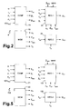
- first regulator 24 comprises a first, a second, and a third regulating line 30, 31, 32 contending a minimum-section port 33; and a first switch stage 35 downstream from minimum-selection port 33.
- First regulating line 30 comprises a first and a second subtraction node 36, 37; a correction stage 38 having a dead-band block 38a and a gain block 38b; a selector 40; and a first generating stage 41.
- power error E PE and the regulation based on it are unaffected by the correction, if speed error E ⁇ is small.
- Power error E PE is supplied to a second input of selector 40, which has an output connected to first generating stage 41 and is controlled by position signal MAIN of main breaker 3. More specifically, if main breaker 3 is open (no-load operation), selector 40 transmits speed error E ⁇ to first generating stage 41; conversely, power error E PE is transmitted.
- ⁇ is a characteristic parameter of the sliding surface.
- first and second regulator 24, 25 use the same parameter ⁇ to synthesize the various sliding surfaces.
- the parameter ⁇ used by second regulator 25 is greater.
- Second regulating line 31 comprises a third subtraction node 43 receiving correct exhaust temperature T EC and maximum temperature T MAX ; and a second generating stage 45.
- Third regulating line 32 comprises a fourth subtraction node 46 receiving current compression ratio ⁇ C and maximum compression ratio ⁇ MAX ; and a third generating stage 47.
- First, second, and third generating stage 41, 45, 47 may advantageously be defined by high-pass filters (filtered derivators) or by observers, which in turn may be sliding-mode types.
- constant H is selected so that: ⁇ MIN ⁇ d ⁇ ⁇ MIN d ⁇ t ⁇ 1 2 ⁇ d ⁇ ⁇ MIN 2 d ⁇ t ⁇ ⁇ H 2 ⁇ MIN
- second regulator 25 comprises a fifth subtraction node 48, a fourth generating stage 50, and a second switch stage 51.
- Second switch stage 51 generates second control signal U IGV , using fourth sliding surface ⁇ 4 and according to the equation :
- U I ⁇ G ⁇ V ⁇ H 2 ⁇ sat ⁇ 4 / ⁇ ⁇ sgn ⁇ 4
- the control device has considerable advantages by employing the sliding-mode control technique.
- discontinuous activation as provided for by sliding-mode techniques, permits maximum control power at all times, so that extremely fast controllers can be achieved, with substantially no oscillation, and capable of finite-time error elimination.
- error saturation problems are also solved.
- the regulators described are highly insensitive to variations in controlled-process parameters, i.e. of turbodrive 5 and mains 2; and, given the robust nature of sliding-mode controllers, design and calibration are greatly simplified, thus also reducing system installation and maintenance cost.
- Second sliding surface ⁇ 2 , third sliding surface ⁇ 3 , and fourth sliding surface ⁇ 4 are generated by second, third, and fourth generating stages 45, 47, 50 respectively, on the basis of the equations :
- FIG. 5 A different embodiment of the invention, which employs second-order sliding-mode control techniques, is shown in Figures 5-7 , in which any parts identical to those already described are indicated using the same reference numbers.
- first and second control signal U FV , U IGV are generated by a first regulator 124 and a second regulator 125 respectively.
- first regulator 124 comprises regulating lines 30, 31, 32, minimum-selection port 33, and a first switch stage 135 connected to the minimum-selection port.
- ⁇ 1 ⁇ / ⁇ t + ⁇ ⁇ E P ⁇ E t
- ⁇ 1 ⁇ / ⁇ t + ⁇ 2 ⁇ E ⁇ t ⁇ d ⁇ t
- ⁇ 1 ⁇ / ⁇ t + ⁇ 2 ⁇ E P ⁇ E t ⁇ d ⁇ t
- the least of sliding surfaces ⁇ 1 , ⁇ 2 , ⁇ 3 is selected by minimum-selection port 33 and sent to first switch stage 135 as minimum sliding surface ⁇ MIN .
- the first control signal U FV so generated satisfies the convergence conditions of the second-order sliding-mode algorithms, and so eliminates in finite time speed error E ⁇ , power error E PE , first temperature error E TE1 , and compression ratio error E ⁇ .
- second regulator 125 comprises fifth subtraction node 48, fourth generating stage 50, and a second switch stage 151.
- Second switch stage 151 receives and uses fourth sliding surface ⁇ 4 to generate second control signal U IGV according to the equation :
- U I ⁇ G ⁇ V ⁇ H 2 ⁇ ⁇ ⁇ 4 ⁇ sat ⁇ 4 / ⁇ ⁇ sgn ⁇ ⁇ 4 ⁇ ⁇ ⁇ ⁇ MAX
- second control signal U IGV also satisfies the convergence conditions of the sliding-mode algorithms, second temperature error E TE2 tends towards zero in finite time.
- Control device 108 also has the further advantage of attenuating so-called “chattering”, i.e. high-frequency oscillations generated about the regulation point by rapid, persistent control signal switching, and which are sometimes caused by poor system modelling (e.g. neglected dominant dynamics).
- chattering i.e. high-frequency oscillations generated about the regulation point by rapid, persistent control signal switching, and which are sometimes caused by poor system modelling (e.g. neglected dominant dynamics).
- the sliding-mode technique may be used solely for the first or second regulator of the control device according to the invention, while synthesis of the other may be based on conventional techniques, such as proportional-integral controllers.
- the regulator supplying second control signal U IGV for the actuator associated with the variable-geometry stage of the compressor is less critical.
- performance of the control device in terms of stability and response would be inferior, but even only one sliding-mode regulator would be sufficient to bring about a big improvement as compared with conventional control devices.
Landscapes
- Engineering & Computer Science (AREA)
- Chemical & Material Sciences (AREA)
- Combustion & Propulsion (AREA)
- General Engineering & Computer Science (AREA)
- Physics & Mathematics (AREA)
- Mechanical Engineering (AREA)
- Artificial Intelligence (AREA)
- Health & Medical Sciences (AREA)
- Fluid Mechanics (AREA)
- Computer Vision & Pattern Recognition (AREA)
- Evolutionary Computation (AREA)
- Medical Informatics (AREA)
- Software Systems (AREA)
- General Physics & Mathematics (AREA)
- Automation & Control Theory (AREA)
- Control Of Eletrric Generators (AREA)
- Control Of Turbines (AREA)
- Engine Equipment That Uses Special Cycles (AREA)
Claims (9)
- Einrichtung zum Steuern eines elektrischen Stromerzeugungssystems, das eine Gasturbine (15); einen Kompressor (12, 13); eine Verbrennungskammer (14); und einen elektrischen Stromerzeuger (6) aufweist, der mechanisch mit der Gasturbine verbunden ist;
wobei die Einrichtung umfasst: ein Regelungsmittel (24, 25; 124, 125), das ein erstes Steuersignal (UFV) zum Steuern von Kraftstoffzufuhr an die Verbrennungskammer (14) liefert, und ein zweites Steuersignal (UIGV) zum Steuern von Lufteinlass durch den Kompressor (12, 13);
dadurch gekennzeichnet, dass das Regelungsmittel (24, 25; 124, 125) eingerichtet ist, das erste (UFV) und zweite (UIGV) Steuersignal in Gleitmodusart zu erzeugen und einen ersten Gleitmodusregulator (24; 124), der das erste Steuersignal (UFV) liefert, umfasst und einen zweiten Gleitmodusregulator (25; 125), der das zweite Steuersignal (IIGV) liefert;
wobei der erste Gleitmodusregulator (24; 124) umfasst:eine erste Schaltstufe (35; 135), die das erste Steuersignal (UFV) auf der Basis eines ersten variablen Satzes (ω, PE, β, TE, TEC) erzeugt, die von dem System erreichbar sind, und auf der Basis von entsprechenden ersten Referenzwerten (ω, PER, βMAX, TMAX), wobei der erste Variablensatz (ω, PE, β, TE, TEC) wenigstens eine Winkelgeschwindigkeit (ω) der Gasturbine (15) aufweist, eine elektrische Wirkleistung (PE), die von dem Erzeuger (6) geliefert wird, eine Auslassgastemperatur (TE, TEC) der Gasturbine (15) und ein Kompressionsverhältnis (β); undeine erste, eine zweite und eine dritte Erzeugungsstufe (41, 45, 47), die eine erste, eine zweite und eine dritte Gleitfläche (σ1, σ2, σ3) liefern, die entsprechend repräsentativ für einen Winkelgeschwindigkeitsfehler (Eω) und einen elektrischen Wirkleistungsfehler (EPE), für einen ersten Auslassgastemperaturfehler (ETE1) und für einen Kompressionsverhältnisfehler (Eβ) sind, wobei die erste Schaltstufe (35; 135) das erste Steuersignal (UFV) auf der Basis einer Minimalfläche (σ-MIN) erzeugt, die aus der ersten, der zweiten und der dritten Gleitfläche (σ1, σ2, σ3) gewählt ist;und wobei der zweite Gleitmodusregulator (25; 125) umfasst:eine zweite Schaltstufe (51; 151), die das zweite Steuersignal (UIGV) auf der Basis eines zweiten Variablensatzes (TE, TEC) erzeugt, der von dem System erreichbar ist, und auf der Basis entsprechender zweiter Referenzwerte (TR), wobei der zweite Variablensatz (TE, TEC) die Auslassgastemperatur aufweist; undeine vierte Erzeugungsstufe (50), die eine vierte Gleitfläche (σ4) liefert, die repräsentativ für einen zweiten Auslassgastemperaturfehler (ETE2) ist, wobei die zweite Schaltstufe (51; 151) das zweite Steuersignal (UIGV) auf der Basis der vierten Gleitfläche (σ4) erzeugt. - Einrichtung, wie in Anspruch 1 beansprucht, dadurch gekennzeichnet, dass sie ein Minimumwahlanschluss (33) zum Empfangen der ersten, der zweiten und der dritten Gleitfläche (σ1, σ2, σ3) aufweist, und die Minimalfläche (σMIN) an die erste Schaltstufe (35; 135) liefert.
- Einrichtung, wie in einem der Ansprüche 1 oder 2 beansprucht, dadurch gekennzeichnet, dass der erste Gleitmodusregulator (24; 124) ein Gleitmodusregulator einer ersten Ordnung oder einer zweiten Ordnung ist.
- Einrichtung, wie in einem der vorhergehenden Ansprüche beansprucht, dadurch gekennzeichnet, dass der zweite Gleitmodusregulator (25; 125) ein Gleitmodusregulator einer ersten Ordnung oder einer zweiten Ordnung ist.
- Elektrisches Stromerzeugungssystem, das eine Gasturbine (15); einen Kompressor (12, 13); eine Verbrennungskammer (14); und einen elektrischen Stromerzeuger (6), der mechanisch mit der Gasturbine verbunden ist, umfasst,
dadurch gekennzeichnet, dass es eine Steuereinrichtung (8; 108), wie in einem der vorhergehenden Ansprüche beansprucht, umfasst. - Verfahren zum Steuern eines elektrischen Stromerzeugungssystems, das eine Gasturbine (15); einen Kompressor (12, 13); eine Verbrennungskammer (14); und einen elektrischen Stromerzeuger (6), der mechanisch mit der Gasturbine verbunden ist, aufweist;
wobei das Verfahren die Schritte umfasst:Erzeugen eines ersten Steuersignals (UFV) zum Steuern einer Kraftstoffzufuhr an die Verbrennungskammer (14); undErzeugen eines zweiten Steuersignals (UIGV) zum Steuern eines Lufteinlasses durch den Kompressor (12, 13);dadurch gekennzeichnet, dass das erste (UFV) und das zweite (UIGV) Steuersignal auf Gleitmodussteuerart erzeugt wird;wobei das erste Steuersignal (UFV) auf der Basis eines ersten Variablensatzes (ω, PE, β, TE, TEC) erzeugt wird, der von dem System erreichbar ist, und auf der Basis entsprechender erster Referenzwerte (ωR, PER, βMAX, TMAX), wobei der erste Variablensatz (ω, PE, β, TE, TEC) wenigstens eine Winkelgeschwindigkeit (ω) der Gasturbine (15) aufweist, eine elektrische Wirkleistung (PE), die von dem Erzeuger (6) geliefert wird, eine Auslassgastemperatur (TE, TEC) der Gasturbine (15) und ein Kompressionsverhältnis (β);wobei der Schritt des Erzeugens des ersten Steuersignals (UFV) das Erzeugen einer ersten, einer zweiten und einer dritten Gleitfläche (σ1, σ2, σ3) umfasst, die entsprechend repräsentativ für einen Winkelgeschwindigkeitsfehler (Eω) und einen elektrischen Wirkleistungsfehler (EPE) sind, für einen ersten Auslassgastemperaturfehler (ETE1) und für einen Kompressionsverhältnisfehler (Eβ), wobei das erste Steuersignal (UFV) auf der Basis einer Minimalfläche (σMIN) erzeugt wird, die aus der ersten, der zweiten und der dritten Gleitfläche (σ1, σ2, σ3) gewählt wird;wobei das zweite Steuersignal (UIGV) auf der Basis eines zweiten Variablensatzes (TE, TEC) erzeugt wird, der von dem System erreichbar ist, und auf der Basis entsprechender zweiter Referenzwerte (TR); wobei der zweite Variablensatz (TE, TEC) die Auslassgastemperatur aufweist; undwobei der Schritt des Erzeugens des zweiten Steuersignals (UIGV) das Erzeugen einer vierten Gleitfläche (σ4) umfasst, die repräsentativ für einen zweiten Auslassgastemperaturfehler (ETE2) ist. - Verfahren, wie in Anspruch 6 beansprucht, dadurch gekennzeichnet, dass das erste Steuersignal (UFV) in Gleitmodussteuerart erster Ordnung oder zweiter Ordnung erzeugt wird.
- Verfahren, wie in Anspruch 6 oder 7 beansprucht, dadurch gekennzeichnet, dass das zweite Steuersignal (UIGV) auf Basis der vierten Gleitfläche (σ4) erzeugt wird.
- Verfahren, wie in einem der Ansprüche 6 bis 8 beansprucht, dadurch gekennzeichnet, dass das zweite Steuersignal (UIGV) in Gleitmodussteuerart erster Ordnung oder zweiter Ordnung erzeugt wird.
Applications Claiming Priority (1)
| Application Number | Priority Date | Filing Date | Title |
|---|---|---|---|
| IT002542A ITMI20042542A1 (it) | 2004-12-29 | 2004-12-29 | Dispositivo e metodo di controllo di un impianto di produzione di energia elettrica a turbina a gas |
Publications (2)
| Publication Number | Publication Date |
|---|---|
| EP1679563A1 EP1679563A1 (de) | 2006-07-12 |
| EP1679563B1 true EP1679563B1 (de) | 2010-10-27 |
Family
ID=36101725
Family Applications (1)
| Application Number | Title | Priority Date | Filing Date |
|---|---|---|---|
| EP05113038A Expired - Lifetime EP1679563B1 (de) | 2004-12-29 | 2005-12-28 | Gerät und Verfahren zur Regelung einer Gasturbine zur elektrischen Stromerzeugung |
Country Status (5)
| Country | Link |
|---|---|
| EP (1) | EP1679563B1 (de) |
| AT (1) | ATE486306T1 (de) |
| DE (1) | DE602005024356D1 (de) |
| ES (1) | ES2351867T3 (de) |
| IT (1) | ITMI20042542A1 (de) |
Families Citing this family (8)
| Publication number | Priority date | Publication date | Assignee | Title |
|---|---|---|---|---|
| WO2008081483A1 (en) * | 2006-12-29 | 2008-07-10 | Ansaldo Energia S.P.A. | Control device and method of a turbine electric power plant supplied with low calorific value gas |
| WO2009016665A1 (en) * | 2007-08-01 | 2009-02-05 | Ansaldo Energia S.P.A. | Device and method for regulating the exhaust temperature of a gas turbine |
| DE602007007324D1 (de) * | 2007-08-14 | 2010-08-05 | Ansaldo Energia Spa | Vorrichtung und Verfahren zur Steuerung einer Gasturbinenanlage |
| ITMI20101428A1 (it) * | 2010-07-29 | 2012-01-30 | Ansaldo Energia Spa | Metodo per la gestione del margine di riserva primaria in un impianto per la produzione di energia elettrica e impianto per la produzione di energia elettrica |
| JP6164994B2 (ja) * | 2013-09-06 | 2017-07-19 | 三菱日立パワーシステムズ株式会社 | ガスタービンプラント、その制御装置、及びガスタービンの運転方法 |
| CN112879167B (zh) * | 2019-11-29 | 2022-01-28 | 中国航发商用航空发动机有限责任公司 | 发动机闭环控制系统及方法 |
| CN111912624A (zh) * | 2020-06-24 | 2020-11-10 | 湖南航翔燃气轮机有限公司 | 可移动式微型燃气轮机发电机组试车台 |
| EP4112908B1 (de) * | 2021-06-30 | 2025-07-30 | ANSALDO ENERGIA S.p.A. | Verfahren zur steuerung eines gasturbinenkraftwerks und gasturbinenkraftwerk |
Family Cites Families (5)
| Publication number | Priority date | Publication date | Assignee | Title |
|---|---|---|---|---|
| IT991920B (it) * | 1973-07-31 | 1975-08-30 | Fiat Spa | Dispositivo per la regolazione di turbine a gas |
| JPH01294915A (ja) * | 1988-05-24 | 1989-11-28 | Toshiba Corp | ガスタービン制御装置 |
| WO1997006471A1 (de) * | 1995-08-08 | 1997-02-20 | Siemens Aktiengesellschaft | Regelsystem mit mindestens zwei reglern sowie verfahren zur minimierung der totzeit eines regelsystems |
| US5857321A (en) * | 1996-06-11 | 1999-01-12 | General Electric Company | Controller with neural network for estimating gas turbine internal cycle parameters |
| JP2002295661A (ja) * | 2001-03-29 | 2002-10-09 | Unisia Jecs Corp | 自動変速機の変速制御装置 |
-
2004
- 2004-12-29 IT IT002542A patent/ITMI20042542A1/it unknown
-
2005
- 2005-12-28 AT AT05113038T patent/ATE486306T1/de not_active IP Right Cessation
- 2005-12-28 DE DE602005024356T patent/DE602005024356D1/de not_active Expired - Lifetime
- 2005-12-28 ES ES05113038T patent/ES2351867T3/es not_active Expired - Lifetime
- 2005-12-28 EP EP05113038A patent/EP1679563B1/de not_active Expired - Lifetime
Also Published As
| Publication number | Publication date |
|---|---|
| EP1679563A1 (de) | 2006-07-12 |
| ES2351867T3 (es) | 2011-02-11 |
| ATE486306T1 (de) | 2010-11-15 |
| DE602005024356D1 (de) | 2010-12-09 |
| ITMI20042542A1 (it) | 2005-03-29 |
Similar Documents
| Publication | Publication Date | Title |
|---|---|---|
| EP1174588B1 (de) | Regeleinrichtung für eine Dampfturbine, die variable Frequenzregelung erlaubt | |
| JPH033927A (ja) | ガスタービンエンジンの制御装置及びその方法 | |
| EP1679563B1 (de) | Gerät und Verfahren zur Regelung einer Gasturbine zur elektrischen Stromerzeugung | |
| CN111095130B (zh) | 用于控制飞机发动机的混合系统和控制其的方法 | |
| EP2647811B1 (de) | Gasturbinensteuervorrichtung und stromerzeugungssystem | |
| RU2172419C1 (ru) | Способ управления многомерным объектом | |
| EP4112908B1 (de) | Verfahren zur steuerung eines gasturbinenkraftwerks und gasturbinenkraftwerk | |
| US20100007304A1 (en) | Drive and method | |
| US12270353B2 (en) | Closed-loop control device for closed-loop control of a power assembly including an internal combustion engine and a generator having an operative drive connection to the internal combustion engine, closed-loop control arrangement having such a closed-loop control device, power assembly and method for closed-loop control of a power assembly | |
| JP2009071908A (ja) | 軸ねじれ振動抑制機能を有する同時同量制御装置 | |
| US12546264B2 (en) | Control device for controlling a power assembly | |
| KR20200096655A (ko) | 가스 터빈의 제어 장치 및 가스 터빈 및 가스 터빈의 제어 방법 | |
| EP1164448A2 (de) | Steuervorrichtung | |
| RU2094620C1 (ru) | Способ управления энергоблоком | |
| JP2007336669A (ja) | 電源系統安定化方法及びその方法を用いた電源系統安定化システム | |
| EP2192292B1 (de) | Drehzahlregler | |
| EP3269963B1 (de) | Modellbasierter stossfreier transfer zwischen passiv- und aktivmodusbetrieb von einem dreiwege-rückschlagventil zur flüssigbrennstoffbereitstellung in einem gasturbinensystem | |
| US20060004470A1 (en) | Multivalue control system and method for controlling a multivalue controlled system | |
| RU2729584C1 (ru) | Способ управления турбогенератором | |
| JPH0228802A (ja) | 制御装置 | |
| Hogg et al. | Optimal PID automatic voltage regulator for synchronous machines | |
| CN121002273A (zh) | 用于控制混合动力涡轮发动机的混合动力率的方法 | |
| AU2022243271A1 (en) | Gas turbine fuel control device | |
| JPS63129104A (ja) | 蒸気タ−ビン加減弁制御切替方法 | |
| KR100805242B1 (ko) | 서보모터의 제어시스템 및 그 제어방법 |
Legal Events
| Date | Code | Title | Description |
|---|---|---|---|
| PUAI | Public reference made under article 153(3) epc to a published international application that has entered the european phase |
Free format text: ORIGINAL CODE: 0009012 |
|
| AK | Designated contracting states |
Kind code of ref document: A1 Designated state(s): AT BE BG CH CY CZ DE DK EE ES FI FR GB GR HU IE IS IT LI LT LU LV MC NL PL PT RO SE SI SK TR |
|
| AX | Request for extension of the european patent |
Extension state: AL BA HR MK YU |
|
| 17P | Request for examination filed |
Effective date: 20070110 |
|
| 17Q | First examination report despatched |
Effective date: 20070212 |
|
| AKX | Designation fees paid |
Designated state(s): AT BE BG CH CY CZ DE DK EE ES FI FR GB GR HU IE IS IT LI LT LU LV MC NL PL PT RO SE SI SK TR |
|
| GRAP | Despatch of communication of intention to grant a patent |
Free format text: ORIGINAL CODE: EPIDOSNIGR1 |
|
| GRAC | Information related to communication of intention to grant a patent modified |
Free format text: ORIGINAL CODE: EPIDOSCIGR1 |
|
| GRAS | Grant fee paid |
Free format text: ORIGINAL CODE: EPIDOSNIGR3 |
|
| GRAA | (expected) grant |
Free format text: ORIGINAL CODE: 0009210 |
|
| AK | Designated contracting states |
Kind code of ref document: B1 Designated state(s): AT BE BG CH CY CZ DE DK EE ES FI FR GB GR HU IE IS IT LI LT LU LV MC NL PL PT RO SE SI SK TR |
|
| REG | Reference to a national code |
Ref country code: GB Ref legal event code: FG4D |
|
| REG | Reference to a national code |
Ref country code: CH Ref legal event code: EP |
|
| REG | Reference to a national code |
Ref country code: IE Ref legal event code: FG4D |
|
| REF | Corresponds to: |
Ref document number: 602005024356 Country of ref document: DE Date of ref document: 20101209 Kind code of ref document: P |
|
| REG | Reference to a national code |
Ref country code: ES Ref legal event code: FG2A Effective date: 20110201 |
|
| REG | Reference to a national code |
Ref country code: NL Ref legal event code: VDEP Effective date: 20101027 |
|
| LTIE | Lt: invalidation of european patent or patent extension |
Effective date: 20101027 |
|
| PGFP | Annual fee paid to national office [announced via postgrant information from national office to epo] |
Ref country code: GB Payment date: 20101222 Year of fee payment: 6 |
|
| PG25 | Lapsed in a contracting state [announced via postgrant information from national office to epo] |
Ref country code: LT Free format text: LAPSE BECAUSE OF FAILURE TO SUBMIT A TRANSLATION OF THE DESCRIPTION OR TO PAY THE FEE WITHIN THE PRESCRIBED TIME-LIMIT Effective date: 20101027 |
|
| PG25 | Lapsed in a contracting state [announced via postgrant information from national office to epo] |
Ref country code: IS Free format text: LAPSE BECAUSE OF FAILURE TO SUBMIT A TRANSLATION OF THE DESCRIPTION OR TO PAY THE FEE WITHIN THE PRESCRIBED TIME-LIMIT Effective date: 20110227 Ref country code: BG Free format text: LAPSE BECAUSE OF FAILURE TO SUBMIT A TRANSLATION OF THE DESCRIPTION OR TO PAY THE FEE WITHIN THE PRESCRIBED TIME-LIMIT Effective date: 20110127 Ref country code: SE Free format text: LAPSE BECAUSE OF FAILURE TO SUBMIT A TRANSLATION OF THE DESCRIPTION OR TO PAY THE FEE WITHIN THE PRESCRIBED TIME-LIMIT Effective date: 20101027 Ref country code: PT Free format text: LAPSE BECAUSE OF FAILURE TO SUBMIT A TRANSLATION OF THE DESCRIPTION OR TO PAY THE FEE WITHIN THE PRESCRIBED TIME-LIMIT Effective date: 20110228 Ref country code: LV Free format text: LAPSE BECAUSE OF FAILURE TO SUBMIT A TRANSLATION OF THE DESCRIPTION OR TO PAY THE FEE WITHIN THE PRESCRIBED TIME-LIMIT Effective date: 20101027 Ref country code: SI Free format text: LAPSE BECAUSE OF FAILURE TO SUBMIT A TRANSLATION OF THE DESCRIPTION OR TO PAY THE FEE WITHIN THE PRESCRIBED TIME-LIMIT Effective date: 20101027 Ref country code: AT Free format text: LAPSE BECAUSE OF FAILURE TO SUBMIT A TRANSLATION OF THE DESCRIPTION OR TO PAY THE FEE WITHIN THE PRESCRIBED TIME-LIMIT Effective date: 20101027 Ref country code: FI Free format text: LAPSE BECAUSE OF FAILURE TO SUBMIT A TRANSLATION OF THE DESCRIPTION OR TO PAY THE FEE WITHIN THE PRESCRIBED TIME-LIMIT Effective date: 20101027 Ref country code: NL Free format text: LAPSE BECAUSE OF FAILURE TO SUBMIT A TRANSLATION OF THE DESCRIPTION OR TO PAY THE FEE WITHIN THE PRESCRIBED TIME-LIMIT Effective date: 20101027 |
|
| PG25 | Lapsed in a contracting state [announced via postgrant information from national office to epo] |
Ref country code: BE Free format text: LAPSE BECAUSE OF FAILURE TO SUBMIT A TRANSLATION OF THE DESCRIPTION OR TO PAY THE FEE WITHIN THE PRESCRIBED TIME-LIMIT Effective date: 20101027 Ref country code: GR Free format text: LAPSE BECAUSE OF FAILURE TO SUBMIT A TRANSLATION OF THE DESCRIPTION OR TO PAY THE FEE WITHIN THE PRESCRIBED TIME-LIMIT Effective date: 20110128 |
|
| PG25 | Lapsed in a contracting state [announced via postgrant information from national office to epo] |
Ref country code: EE Free format text: LAPSE BECAUSE OF FAILURE TO SUBMIT A TRANSLATION OF THE DESCRIPTION OR TO PAY THE FEE WITHIN THE PRESCRIBED TIME-LIMIT Effective date: 20101027 Ref country code: CZ Free format text: LAPSE BECAUSE OF FAILURE TO SUBMIT A TRANSLATION OF THE DESCRIPTION OR TO PAY THE FEE WITHIN THE PRESCRIBED TIME-LIMIT Effective date: 20101027 Ref country code: MC Free format text: LAPSE BECAUSE OF NON-PAYMENT OF DUE FEES Effective date: 20101231 |
|
| REG | Reference to a national code |
Ref country code: CH Ref legal event code: PL |
|
| PG25 | Lapsed in a contracting state [announced via postgrant information from national office to epo] |
Ref country code: DK Free format text: LAPSE BECAUSE OF FAILURE TO SUBMIT A TRANSLATION OF THE DESCRIPTION OR TO PAY THE FEE WITHIN THE PRESCRIBED TIME-LIMIT Effective date: 20101027 Ref country code: RO Free format text: LAPSE BECAUSE OF FAILURE TO SUBMIT A TRANSLATION OF THE DESCRIPTION OR TO PAY THE FEE WITHIN THE PRESCRIBED TIME-LIMIT Effective date: 20101027 Ref country code: PL Free format text: LAPSE BECAUSE OF FAILURE TO SUBMIT A TRANSLATION OF THE DESCRIPTION OR TO PAY THE FEE WITHIN THE PRESCRIBED TIME-LIMIT Effective date: 20101027 Ref country code: SK Free format text: LAPSE BECAUSE OF FAILURE TO SUBMIT A TRANSLATION OF THE DESCRIPTION OR TO PAY THE FEE WITHIN THE PRESCRIBED TIME-LIMIT Effective date: 20101027 |
|
| PLBE | No opposition filed within time limit |
Free format text: ORIGINAL CODE: 0009261 |
|
| STAA | Information on the status of an ep patent application or granted ep patent |
Free format text: STATUS: NO OPPOSITION FILED WITHIN TIME LIMIT |
|
| 26N | No opposition filed |
Effective date: 20110728 |
|
| PG25 | Lapsed in a contracting state [announced via postgrant information from national office to epo] |
Ref country code: IE Free format text: LAPSE BECAUSE OF NON-PAYMENT OF DUE FEES Effective date: 20101228 Ref country code: LI Free format text: LAPSE BECAUSE OF NON-PAYMENT OF DUE FEES Effective date: 20101231 Ref country code: CH Free format text: LAPSE BECAUSE OF NON-PAYMENT OF DUE FEES Effective date: 20101231 |
|
| REG | Reference to a national code |
Ref country code: DE Ref legal event code: R097 Ref document number: 602005024356 Country of ref document: DE Effective date: 20110728 |
|
| PG25 | Lapsed in a contracting state [announced via postgrant information from national office to epo] |
Ref country code: IT Free format text: LAPSE BECAUSE OF FAILURE TO SUBMIT A TRANSLATION OF THE DESCRIPTION OR TO PAY THE FEE WITHIN THE PRESCRIBED TIME-LIMIT Effective date: 20101027 |
|
| PGFP | Annual fee paid to national office [announced via postgrant information from national office to epo] |
Ref country code: FR Payment date: 20111220 Year of fee payment: 7 Ref country code: ES Payment date: 20111216 Year of fee payment: 7 |
|
| PGFP | Annual fee paid to national office [announced via postgrant information from national office to epo] |
Ref country code: DE Payment date: 20120126 Year of fee payment: 7 |
|
| PG25 | Lapsed in a contracting state [announced via postgrant information from national office to epo] |
Ref country code: CY Free format text: LAPSE BECAUSE OF FAILURE TO SUBMIT A TRANSLATION OF THE DESCRIPTION OR TO PAY THE FEE WITHIN THE PRESCRIBED TIME-LIMIT Effective date: 20101027 |
|
| PG25 | Lapsed in a contracting state [announced via postgrant information from national office to epo] |
Ref country code: LU Free format text: LAPSE BECAUSE OF NON-PAYMENT OF DUE FEES Effective date: 20101228 Ref country code: HU Free format text: LAPSE BECAUSE OF FAILURE TO SUBMIT A TRANSLATION OF THE DESCRIPTION OR TO PAY THE FEE WITHIN THE PRESCRIBED TIME-LIMIT Effective date: 20110428 |
|
| PG25 | Lapsed in a contracting state [announced via postgrant information from national office to epo] |
Ref country code: TR Free format text: LAPSE BECAUSE OF FAILURE TO SUBMIT A TRANSLATION OF THE DESCRIPTION OR TO PAY THE FEE WITHIN THE PRESCRIBED TIME-LIMIT Effective date: 20101027 |
|
| GBPC | Gb: european patent ceased through non-payment of renewal fee |
Effective date: 20121228 |
|
| REG | Reference to a national code |
Ref country code: FR Ref legal event code: ST Effective date: 20130830 |
|
| REG | Reference to a national code |
Ref country code: DE Ref legal event code: R119 Ref document number: 602005024356 Country of ref document: DE Effective date: 20130702 |
|
| PG25 | Lapsed in a contracting state [announced via postgrant information from national office to epo] |
Ref country code: DE Free format text: LAPSE BECAUSE OF NON-PAYMENT OF DUE FEES Effective date: 20130702 |
|
| PG25 | Lapsed in a contracting state [announced via postgrant information from national office to epo] |
Ref country code: GB Free format text: LAPSE BECAUSE OF NON-PAYMENT OF DUE FEES Effective date: 20121228 Ref country code: FR Free format text: LAPSE BECAUSE OF NON-PAYMENT OF DUE FEES Effective date: 20130102 |
|
| REG | Reference to a national code |
Ref country code: ES Ref legal event code: FD2A Effective date: 20140306 |
|
| PG25 | Lapsed in a contracting state [announced via postgrant information from national office to epo] |
Ref country code: ES Free format text: LAPSE BECAUSE OF NON-PAYMENT OF DUE FEES Effective date: 20121229 |