EP1679480A1 - Thermoelectric generator - Google Patents
Thermoelectric generator Download PDFInfo
- Publication number
- EP1679480A1 EP1679480A1 EP05028045A EP05028045A EP1679480A1 EP 1679480 A1 EP1679480 A1 EP 1679480A1 EP 05028045 A EP05028045 A EP 05028045A EP 05028045 A EP05028045 A EP 05028045A EP 1679480 A1 EP1679480 A1 EP 1679480A1
- Authority
- EP
- European Patent Office
- Prior art keywords
- passage
- cooling water
- engine
- heat source
- fluid
- Prior art date
- Legal status (The legal status is an assumption and is not a legal conclusion. Google has not performed a legal analysis and makes no representation as to the accuracy of the status listed.)
- Pending
Links
- 239000012530 fluid Substances 0.000 claims abstract description 30
- 238000001816 cooling Methods 0.000 claims abstract description 15
- 239000002918 waste heat Substances 0.000 claims description 6
- 238000010438 heat treatment Methods 0.000 claims description 2
- 239000000498 cooling water Substances 0.000 description 94
- XLYOFNOQVPJJNP-UHFFFAOYSA-N water Substances O XLYOFNOQVPJJNP-UHFFFAOYSA-N 0.000 description 15
- 230000005679 Peltier effect Effects 0.000 description 4
- 238000010586 diagram Methods 0.000 description 3
- 230000004048 modification Effects 0.000 description 3
- 238000012986 modification Methods 0.000 description 3
- 238000011144 upstream manufacturing Methods 0.000 description 3
- 238000010792 warming Methods 0.000 description 3
- 230000005678 Seebeck effect Effects 0.000 description 2
- 230000007423 decrease Effects 0.000 description 2
- 230000003247 decreasing effect Effects 0.000 description 2
- 230000006866 deterioration Effects 0.000 description 2
- 238000011084 recovery Methods 0.000 description 2
- 239000004065 semiconductor Substances 0.000 description 2
- 238000004378 air conditioning Methods 0.000 description 1
- 238000002485 combustion reaction Methods 0.000 description 1
- 230000000694 effects Effects 0.000 description 1
- 239000000446 fuel Substances 0.000 description 1
- 239000004519 grease Substances 0.000 description 1
- 239000002184 metal Substances 0.000 description 1
- 239000000615 nonconductor Substances 0.000 description 1
- 238000010248 power generation Methods 0.000 description 1
Images

Classifications
-
- F—MECHANICAL ENGINEERING; LIGHTING; HEATING; WEAPONS; BLASTING
- F01—MACHINES OR ENGINES IN GENERAL; ENGINE PLANTS IN GENERAL; STEAM ENGINES
- F01P—COOLING OF MACHINES OR ENGINES IN GENERAL; COOLING OF INTERNAL-COMBUSTION ENGINES
- F01P3/00—Liquid cooling
- F01P3/20—Cooling circuits not specific to a single part of engine or machine
-
- F—MECHANICAL ENGINEERING; LIGHTING; HEATING; WEAPONS; BLASTING
- F01—MACHINES OR ENGINES IN GENERAL; ENGINE PLANTS IN GENERAL; STEAM ENGINES
- F01P—COOLING OF MACHINES OR ENGINES IN GENERAL; COOLING OF INTERNAL-COMBUSTION ENGINES
- F01P7/00—Controlling of coolant flow
- F01P7/14—Controlling of coolant flow the coolant being liquid
- F01P7/16—Controlling of coolant flow the coolant being liquid by thermostatic control
- F01P7/165—Controlling of coolant flow the coolant being liquid by thermostatic control characterised by systems with two or more loops
-
- F—MECHANICAL ENGINEERING; LIGHTING; HEATING; WEAPONS; BLASTING
- F02—COMBUSTION ENGINES; HOT-GAS OR COMBUSTION-PRODUCT ENGINE PLANTS
- F02G—HOT GAS OR COMBUSTION-PRODUCT POSITIVE-DISPLACEMENT ENGINE PLANTS; USE OF WASTE HEAT OF COMBUSTION ENGINES; NOT OTHERWISE PROVIDED FOR
- F02G5/00—Profiting from waste heat of combustion engines, not otherwise provided for
-
- H—ELECTRICITY
- H10—SEMICONDUCTOR DEVICES; ELECTRIC SOLID-STATE DEVICES NOT OTHERWISE PROVIDED FOR
- H10N—ELECTRIC SOLID-STATE DEVICES NOT OTHERWISE PROVIDED FOR
- H10N10/00—Thermoelectric devices comprising a junction of dissimilar materials, i.e. devices exhibiting Seebeck or Peltier effects
-
- F—MECHANICAL ENGINEERING; LIGHTING; HEATING; WEAPONS; BLASTING
- F01—MACHINES OR ENGINES IN GENERAL; ENGINE PLANTS IN GENERAL; STEAM ENGINES
- F01P—COOLING OF MACHINES OR ENGINES IN GENERAL; COOLING OF INTERNAL-COMBUSTION ENGINES
- F01P7/00—Controlling of coolant flow
- F01P7/14—Controlling of coolant flow the coolant being liquid
- F01P2007/146—Controlling of coolant flow the coolant being liquid using valves
-
- F—MECHANICAL ENGINEERING; LIGHTING; HEATING; WEAPONS; BLASTING
- F01—MACHINES OR ENGINES IN GENERAL; ENGINE PLANTS IN GENERAL; STEAM ENGINES
- F01P—COOLING OF MACHINES OR ENGINES IN GENERAL; COOLING OF INTERNAL-COMBUSTION ENGINES
- F01P2025/00—Measuring
- F01P2025/08—Temperature
- F01P2025/50—Temperature using two or more temperature sensors
-
- Y—GENERAL TAGGING OF NEW TECHNOLOGICAL DEVELOPMENTS; GENERAL TAGGING OF CROSS-SECTIONAL TECHNOLOGIES SPANNING OVER SEVERAL SECTIONS OF THE IPC; TECHNICAL SUBJECTS COVERED BY FORMER USPC CROSS-REFERENCE ART COLLECTIONS [XRACs] AND DIGESTS
- Y02—TECHNOLOGIES OR APPLICATIONS FOR MITIGATION OR ADAPTATION AGAINST CLIMATE CHANGE
- Y02T—CLIMATE CHANGE MITIGATION TECHNOLOGIES RELATED TO TRANSPORTATION
- Y02T10/00—Road transport of goods or passengers
- Y02T10/10—Internal combustion engine [ICE] based vehicles
- Y02T10/12—Improving ICE efficiencies
Definitions
- the present invention relates to a thermoelectric generator that recovers electric energy from waste heat energy generated in an engine by using a thermoelectric element.
- thermoelectric element It is known to recover electric energy from waste heat energy generated in an internal combustion engine (hereafter, engine) by a thermoelectric element.
- engine an internal combustion engine
- thermoelectric element a thermoelectric element
- electric energy is recovered by using cooling water, which circulates in a cooling water circuit connecting an engine and a first radiator, as a high temperature heat source part of a thermoelectric element and a second radiator, which is cooled by air or water, as a low temperature heat source part of the thermoelectric element.
- the high temperature heat source part is constructed of a tank and is connected to the first radiator in series in the cooling water circuit.
- a heat recovering means (thermoelectric element) is provided between a primary cooling water circuit through which a primary cooling water flows and a secondary cooling water circuit through which a secondary cooling water flows, thereby to recover electric energy by using a temperature difference produced between the primary cooling water and the secondary cooling water.
- the primary cooling water circuit includes a cooling water jacket provided on an engine body as one element of a closed circuit, and has a first cooling water pump for circulating the primary cooling water therein.
- the secondary cooling water circuit is provided separate from the primary cooling water circuit and is constructed of a radiator as one element of a closed circuit.
- the secondary cooling water circuit is provided with a water pump. A circulation rate of the secondary cooling water is adjusted in accordance with an engine operation condition, thereby to control the temperature of the primary cooling water through the thermal-element for cooling the engine body.
- thermoelectric element Since the temperature of the primary cooling water is controlled by the flow rate control of the secondary cooling water through the thermoelectric element, the thermoelectric element is required to increase a coefficient of thermal conductivity for this temperature control. However, if the coefficient of thermal conductivity is increased, it is difficult to sufficiently maintain the temperature difference on the surfaces of the thermoelectric element. Further, this results in deterioration of recovery efficiency (i.e. generation efficiency) on recovering electric energy (i.e. on generating electric power). On the contrary, if the coefficient of thermal conductivity of the thermoelectric element is reduced, it is required to increase the capacity of the radiator and the motive power of the water pump of the secondary cooling water circuit for cooling the engine body.
- the present invention is made in view of the foregoing matter, and it is an object of the present invention to provide a thermoelectric generator capable of generating electric power through a thermoelectric element while sufficiently maintaining a capacity to cool an engine and suppressing a decrease of a flow rate of a cooling water in a radiator.
- a thermoelectric generator has a high temperature heat source part, a low temperature heat source part and a thermoelectric element.
- the high temperature heat source part is provided on a first passage through which a first fluid for cooling an engine flows for receiving heat from the first fluid.
- the low temperature heat source part that is provided on a second passage through which a second fluid flows for receiving heat from the second fluid.
- the second passage is provided separate from the first passage.
- the second fluid has a temperature lower than the first fluid.
- the thermoelectric element is provided between the high temperature heat source part and the low temperature heat source part for producing electric power by a temperature difference between the high temperature heat source part and the low temperature heat source part.
- the first passage is included in a first circuit.
- the engine and a first radiator for cooling the first fluid are connected in loop through a main passage. Further, the first passage is arranged in parallel to the first radiator.
- the second passage is included in a second circuit that is separate from the first circuit. The second circuit has a second radiator for cooling the second fluid.
- the high temperature heat source part is arranged in parallel to the first radiator in the first circuit, it is less likely that the flow rate of the first fluid in the first radiator will be reduced by the high temperature heat source part. Accordingly, the first fluid is sufficiently cooled without requiring the increase of the size of the first radiator, and therefore, the engine is maintained at a predetermined temperature.
- thermoelectric element it is not necessary to transfer heat of the first fluid from the high temperature heat source part to the low temperature heat source part through the thermoelectric element. Therefore, the coefficient of heat conductivity of the thermoelectric element is set at a low level. Furthermore, because the second fluid circulating in the second circuit is cooled through the second radiator, the temperature of the low temperature heat source part is maintained at a low level. Accordingly, electric energy is effectively produced by the thermoelectric element while maintaining the temperature difference between the high temperature heat source part and the low temperature heat source part at a constant level.
- thermoelectric generator system 100 is mainly constructed of a thermoelectric generator 110 and a control device 120 for controlling operation of the thermoelectric generator 110.
- the thermoelectric generator system 100 is used in a vehicle having a water-cooled engine 10 for recovering electric energy from waste heat energy of the engine 10.
- electric power is produced at a thermoelectric element 113 by a temperature difference between a high temperature heat source part 111 and a low temperature heat source part 112.
- the engine 10 is provided with an engine cooling water circuit (first circuit) 20.
- a main passage of the engine cooling water circuit 20 is constructed such that engine cooling water (first fluid) passing through the engine 10 is circulated from a first outlet portion 11 to an inlet portion 13 through an engine cooling water radiator (hereafter, referred to as a first radiator) 21 by a water pump 14.
- the water pump 14 is located close to the inlet portion 13 and is driven by the engine 10.
- the engine cooling water circuit 20 is provided with a bypass passage 22 bypassing the first radiator 21, and a thermostat 24.
- the thermostat 24 is located at a confluence where the bypass passage 22 meets with the main passage at a position downstream of the first radiator 21.
- the thermostat 24 is provided to adjust a flow rate of the engine cooling water of the main passage communicating with the first radiator 21 and a flow rate of the engine cooling water of the bypass passage 22.
- the thermostat 24 closes the main passage when the temperature of engine cooling water is equal to or lower than a predetermined first temperature (e.g. 85 °C). When the temperature of engine cooling water exceeds the first predetermined temperature, the thermostat 24 begins to open the main passage. When the temperature of engine cooling water is equal to or higher than a second predetermined temperature (e.g. 90 °C), the thermostat 24 closes the bypass passage 22 and fully opens the main passage.
- a predetermined first temperature e.g. 85 °C
- a second predetermined temperature e.g. 90 °C
- the engine cooling water circuit 20 is provided with a parallel passage (first passage) 23 that is arranged in parallel to the first radiator 21.
- the parallel passage 23 diverges from the main passage between the first radiator 21 and the bypass passage 22, at an upstream position of the first radiator 21.
- the parallel passage 23 meets with the main passage between the thermostat 24 and the water pump 14.
- a flow rate adjustment valve 25 is provided at the diverging point of the parallel passage 23.
- a switching valve 26 is provided at the confluence of the parallel passage 23 and the main passage. The switching valve 26 switches the passage so that at least one of the engine cooling water flowing from the parallel passage 23 and the engine cooling water flowing through the main passage from the thermostat 24 is introduced toward the engine 10.
- a switching valve 27 is provided at a diverging point where the bypass passage 22 diverges from the main passage of the engine cooling water circuit 20.
- the switching valve 27 switches the main passage and the bypass passage 22.
- the opening degree of the flow rate adjustment valve 25, and the switching operation of the switching valves 26, 27 are controlled by the control device 120.
- thermoelectric generator system 100 has a low temperature circuit (second circuit, second passage) 30 through which low temperature cooling water (second fluid) circulates.
- the low temperature circuit 30 is operated separate from the engine cooling water circuit 20.
- a low temperature cooling water radiator hereafter, referred to as a second radiator
- an electric pump 32 is provided on the low temperature circuit 30 for circulating the low temperature cooling water therein.
- the low temperature cooling water is cooled through the second radiator 31, so the temperature of the low temperature cooling water is maintained lower than the temperature of the engine cooling water of the engine cooling water circuit 20.
- the electric pump 32 is controlled by the control device 120.
- the engine 10 is provided with a heater hot water circuit 40 through which the engine cooling water circulates.
- the heater hot water circuit 40 extends from a second outlet portion 12 and meets with the main passage of the engine cooling water circuit 20 at a position upstream of the water pump 14 through a heater core 41.
- the heater core 41 is a heat exchanger that heats air for an air-conditioning system by using heat of the engine cooling water (hot water).
- the thermoelectric generator 110 uses the engine cooling water of the cooling water circuit 20 and the low temperature cooling water of the low temperature side circuit 30 as the heat sources.
- the thermoelectric generator 110 is constructed of the high temperature heat source part 111, the low temperature heat source part 112, and the thermoelectric element 113.
- thermoelectric element (thermoelectric module) 113 is a known element that produces electric power by Seebeck effect and generates heat by Peltier effect.
- the thermoelectric element 113 is constructed by alternately arranging p-type semiconductors and n-type semiconductors in series through metal electrodes.
- Each of the high temperature heat source part 111 and the low temperature heat source part 112 is provided as a heat exchanger and constructed of a metallic container device having a flat shape. Further, inner fins are inserted therein.
- the high temperature heat source part 111 and the low temperature heat source part 112 are closely attached to a first side and a second side of the thermoelectric element 113, respectively. Between the thermoelectric element 113 and the high temperature side heat source 111 and between the thermoelectric element 113 and the low temperature side heat source 112, electrical insulators are sandwiched and thermal conductive grease is applied for reducing contact heat resistance. Alternatively, heat-transfer sheets are sandwiched between them.
- the high temperature heat source part 111 is arranged on the parallel passage 23, so that the engine cooling water of the engine cooling water circuit 20 passes through the high temperature heat source part 111.
- the low temperature side heat source part 112 is arranged on the low temperature side circuit 30, so that the low temperature cooling water of the low temperature side circuit 30 passes through the low temperature heat source part 112. That is, the thermoelectric generator 110 is constructed such that the thermoelectric element 113 uses the engine cooling water flowing through the parallel passage 23 and the low temperature cooling water flowing through the low temperature side circuit 30 as a high temperature side heat source and a low temperature side heat source, respectively.
- the control device 120 receives signals such as an outside air temperature signal and a cooling water temperature signal from an outside air temperature sensor S1 and an engine cooling water sensor S2, respectively. Also, the control device 120 receives an operation condition of the thermoelectric generator 110. The control device 120 controls the flow rate adjustment valve 25, the switching valves 26, 27 and the electric pump 32 based on the above information.
- control device 120 controls an inverter (power converting device) 130. Specifically, when the electric power is produced by the thermoelectric element 113, the generated electric power is stored in a battery 140 through the inverter 130. Also, the electric power is sent to the thermoelectric element 113 from the battery 140 through the inverter 130 in accordance with the outside temperature signal and the cooling water temperature signal.
- the control device 120, the inverter 130 and the battery 140 provide an electric power supply means (electric power supply unit).
- the thermostat 24 closes the bypass passage 22 and opens the main passage communicating with the first radiator 21.
- the switching valve 26 is controlled such that both the main passage from the thermostat 24 and the parallel passage 23 communicate with the water pump 14, as shown in Fig. 1.
- the switching valve 27 is controlled to open the main passage so that the engine cooling water flows to the first radiator 21.
- the electric pump 32 of the low temperature side circuit 30 is operated.
- the engine cooling water diverges into the main passage for passing through the first radiator 21 (solid line arrow in Fig. 1) and the parallel passage 23 for returning to the main passage while bypassing the first radiator 21 (broken-line arrow in Fig. 1).
- the low temperature cooling water of the low temperature side circuit 30 circulates through the second radiator 31 (dashed-line arrow in Fig. 1). Further, the engine cooling water passes through the high temperature heat source part 111, and the low temperature cooling water passes through the low temperature heat source part 112.
- the engine cooling water is cooled through the radiator 21, and therefore, the temperature of the engine 10 is maintained at a predetermined level. Also, a constant temperature difference is produced between the heat source parts 111, 112 by the engine cooling water and the low temperature cooling water. Therefore, the thermoelectric element 113 produces electric power by Seebeck effect. At this time, the inverter 130 is operated so that the produced electric power is stored in the battery 140.
- the opening degree of the flow rate adjustment valve 25 is controlled in accordance with the temperature of the engine cooling water, thereby to control the amount of electric power to be generated. Namely, when a cooling power required to the first radiator 21 is large, that is, when the temperature of the engine cooling water is high, the flow rate to the first radiator 21 is increased. On the contrary, when the cooling power required to the first radiator 21 is small, that is, when the temperature of the engine cooling water is low, the flow rate to the parallel passage 23 is increased. Accordingly, the amount of electric power generated in the thermoelectric element 113 is increased. 2. On starting up the engine 10
- the thermostat 24 On starting up the engine 10, when both the temperature signals from the outside air temperature sensor S1 and the engine water temperature sensor S2 are higher than 10 °C, the thermostat 24 opens the bypass passage 22 and closes the main passage from the first radiator 21. At this time, the switching valve 26 is controlled to open only the main passage so that the thermostat 24 communicates with the water pump 14, as shown in Fig. 2. Also, the switching valve 27 is controlled to open the bypass passage 22. Furthermore, the electric pump 32 of the low temperature side circuit 30 is stopped.
- the engine cooling water only flows through the bypass passage 22 (solid line arrow in Fig. 2), thereby to warm up the engine 10. This operation corresponds to a normal warming operation by the bypass passage 22. At this time, the electric power is not produced from the thermoelectric element 113.
- the thermostat 24 opens the bypass passage 22 and closes the main passage from the radiator 21.
- the switching valve 26 is controlled to open only the parallel passage 23, as shown in Fig. 3.
- the switching valve 27 is controlled to open the main passage and close the bypass passage 22.
- the opening degree of the flow rate adjustment valve 25 is controlled so that the parallel passage 23 is fully open and the main passage to the first radiator 21 is fully closed.
- the inverter 130 is controlled to introduce the electric power from the battery 140 to the thermoelectric element 113. That is, the thermoelectric element 113 is supplied with the electric power.
- the electric pump 32 of the low temperature side circuit 30 is stopped.
- the cooling water in the engine cooling water circuit 20 flows through the parallel passage 23 and the high temperature side heat source 111, and then returns to the engine 10 (broken line arrow in Fig. 3). Particularly, the cooling water is heated while flowing through the high temperature heat source part 111 by Peltier effect of the thermoelectric element 113. Therefore, the warming of the engine 10 is facilitated.
- the high temperature heat source part 111 is arranged in parallel to the radiator 21 in the engine cooling water circuit 20. Therefore, it is less likely that the flow rate of the engine cooling water in the radiator 21 is decreased by the high temperature heat source part 111. Further, the engine cooling water is sufficiently cooled by the first radiator 21 without requiring an increase of the size of first radiator 21 and an increase of capacity of the water pump 14. Furthermore, the temperature of the engine 10 is maintained at a predetermined level.
- thermoelectric element 113 Because it is not necessary to transfer heat from the high temperature heat source part 111 to the low temperature side heat source 112 through the thermoelectric element 113, the coefficient of thermal conductivity of the thermoelectric element 113 is set at a low level. Further, the low temperature cooling water of the low temperature side circuit 30 is cooled through the second radiator 31. Therefore, the temperature of the low temperature heat source part 112 is constantly maintained at a low level. With this, the constant temperature difference is maintained between the high temperature heat source part 111 and the low temperature heat source part 112. Accordingly, the electric power is effectively produced by the thermoelectric element 113.
- the flow rate of the engine cooling water to the first radiator 21 and the flow rate of the parallel passage 23 are adjusted by the flow rate adjustment valve 25 in accordance with the cooling power required to the first radiator 21, that is, in accordance with the temperature of the engine cooling water. Accordingly, the electric power is produced through the thermoelectric element 113 by effectively using the waste heat of the engine 10.
- thermoelectric element 113 is supplied with the electric power and the cooling water passing through the high temperature heat source part 111 is heated by Peltier effect of the thermoelectric element 113. Accordingly, the warming of the engine 10 is facilitated. With this, friction loss is decreased and emission characteristic is improved. Furthermore, the fuel economy of the engine 10 is enhanced.
- the above embodiment is for example modified as follows. First, in a case that the heating control of the cooling water by Peltier effect of the thermoelectric element 113 is not required during the cold starting, the position of the confluence of the parallel passage 23 to the main passage of the engine cooling water circuit 20 is changed to a position upstream of the thermostat 24. In this case, the switching valves 26, 27 are not required. (Modification 1).
Landscapes
- Engineering & Computer Science (AREA)
- Chemical & Material Sciences (AREA)
- Combustion & Propulsion (AREA)
- Mechanical Engineering (AREA)
- General Engineering & Computer Science (AREA)
- Air-Conditioning For Vehicles (AREA)
- Cooling, Air Intake And Gas Exhaust, And Fuel Tank Arrangements In Propulsion Units (AREA)
Abstract
Description
- The present invention relates to a thermoelectric generator that recovers electric energy from waste heat energy generated in an engine by using a thermoelectric element.
- It is known to recover electric energy from waste heat energy generated in an internal combustion engine (hereafter, engine) by a thermoelectric element. For example, in an engine cooling water circulation system disclosed in Japanese Unexamined Patent Publication No. JP-A-10-238406, electric energy is recovered by using cooling water, which circulates in a cooling water circuit connecting an engine and a first radiator, as a high temperature heat source part of a thermoelectric element and a second radiator, which is cooled by air or water, as a low temperature heat source part of the thermoelectric element. Further, the high temperature heat source part is constructed of a tank and is connected to the first radiator in series in the cooling water circuit.
- In the above system, however, a resistance to the cooling water in the cooling water circuit is increased by the high temperature heat source part. Therefore, a flow rate of the cooling water in the first radiator decreases. This results in deterioration of cooling performance. To solve this matter, for example, it is required to increase the size of the first radiator and to improve the capacity of a pump for circulating the cooling water in the circuit.
- In a waste heat recovery device disclosed in Japanese Unexamined Patent Publication NO. JP-A-9-32636, a heat recovering means (thermoelectric element) is provided between a primary cooling water circuit through which a primary cooling water flows and a secondary cooling water circuit through which a secondary cooling water flows, thereby to recover electric energy by using a temperature difference produced between the primary cooling water and the secondary cooling water.
- In the above device, the primary cooling water circuit includes a cooling water jacket provided on an engine body as one element of a closed circuit, and has a first cooling water pump for circulating the primary cooling water therein. On the contrary, the secondary cooling water circuit is provided separate from the primary cooling water circuit and is constructed of a radiator as one element of a closed circuit. The secondary cooling water circuit is provided with a water pump. A circulation rate of the secondary cooling water is adjusted in accordance with an engine operation condition, thereby to control the temperature of the primary cooling water through the thermal-element for cooling the engine body.
- Since the temperature of the primary cooling water is controlled by the flow rate control of the secondary cooling water through the thermoelectric element, the thermoelectric element is required to increase a coefficient of thermal conductivity for this temperature control. However, if the coefficient of thermal conductivity is increased, it is difficult to sufficiently maintain the temperature difference on the surfaces of the thermoelectric element. Further, this results in deterioration of recovery efficiency (i.e. generation efficiency) on recovering electric energy (i.e. on generating electric power). On the contrary, if the coefficient of thermal conductivity of the thermoelectric element is reduced, it is required to increase the capacity of the radiator and the motive power of the water pump of the secondary cooling water circuit for cooling the engine body.
- The present invention is made in view of the foregoing matter, and it is an object of the present invention to provide a thermoelectric generator capable of generating electric power through a thermoelectric element while sufficiently maintaining a capacity to cool an engine and suppressing a decrease of a flow rate of a cooling water in a radiator.
- According to the present invention, a thermoelectric generator has a high temperature heat source part, a low temperature heat source part and a thermoelectric element. The high temperature heat source part is provided on a first passage through which a first fluid for cooling an engine flows for receiving heat from the first fluid. The low temperature heat source part that is provided on a second passage through which a second fluid flows for receiving heat from the second fluid. The second passage is provided separate from the first passage. The second fluid has a temperature lower than the first fluid. The thermoelectric element is provided between the high temperature heat source part and the low temperature heat source part for producing electric power by a temperature difference between the high temperature heat source part and the low temperature heat source part.
- The first passage is included in a first circuit. In the first circuit, the engine and a first radiator for cooling the first fluid are connected in loop through a main passage. Further, the first passage is arranged in parallel to the first radiator. The second passage is included in a second circuit that is separate from the first circuit. The second circuit has a second radiator for cooling the second fluid.
- Since the high temperature heat source part is arranged in parallel to the first radiator in the first circuit, it is less likely that the flow rate of the first fluid in the first radiator will be reduced by the high temperature heat source part. Accordingly, the first fluid is sufficiently cooled without requiring the increase of the size of the first radiator, and therefore, the engine is maintained at a predetermined temperature.
- Further, it is not necessary to transfer heat of the first fluid from the high temperature heat source part to the low temperature heat source part through the thermoelectric element. Therefore, the coefficient of heat conductivity of the thermoelectric element is set at a low level. Furthermore, because the second fluid circulating in the second circuit is cooled through the second radiator, the temperature of the low temperature heat source part is maintained at a low level. Accordingly, electric energy is effectively produced by the thermoelectric element while maintaining the temperature difference between the high temperature heat source part and the low temperature heat source part at a constant level.
- Other objects, features and advantages of the present invention will become more apparent from the following detailed description made with reference to the accompanying drawings, in which like parts are designated by like reference numbers and in which:
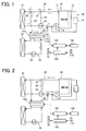
- Fig. 1 is a schematic block diagram of a thermoelectric generator system according to an embodiment of the present invention;
- Fig. 2 is a schematic block diagram of the thermoelectric generator system for showing a flow of engine cooling water on starting an engine according to the embodiment of the present invention; and
- Fig. 3 is a schematic block diagram of the thermoelectric generator system for showing a flow of engine cooling water on cold-starting the engine according to the embodiment of the present invention.
- Embodiments of the present invention will be described hereinafter with reference to the drawing.
- Referring to Fig. 1, a thermoelectric generator system 100 is mainly constructed of a
thermoelectric generator 110 and acontrol device 120 for controlling operation of thethermoelectric generator 110. The thermoelectric generator system 100 is used in a vehicle having a water-cooledengine 10 for recovering electric energy from waste heat energy of theengine 10. Specifically, in thethermoelectric generator 110, electric power is produced at athermoelectric element 113 by a temperature difference between a high temperatureheat source part 111 and a low temperatureheat source part 112. - First, the basic configuration of the thermoelectric generator system 100 will be described with reference to Fig. 1. The
engine 10 is provided with an engine cooling water circuit (first circuit) 20. A main passage of the enginecooling water circuit 20 is constructed such that engine cooling water (first fluid) passing through theengine 10 is circulated from afirst outlet portion 11 to aninlet portion 13 through an engine cooling water radiator (hereafter, referred to as a first radiator) 21 by awater pump 14. Here, thewater pump 14 is located close to theinlet portion 13 and is driven by theengine 10. - Further, the engine
cooling water circuit 20 is provided with abypass passage 22 bypassing thefirst radiator 21, and athermostat 24. Thethermostat 24 is located at a confluence where thebypass passage 22 meets with the main passage at a position downstream of thefirst radiator 21. Thethermostat 24 is provided to adjust a flow rate of the engine cooling water of the main passage communicating with thefirst radiator 21 and a flow rate of the engine cooling water of thebypass passage 22. - Specifically, the
thermostat 24 closes the main passage when the temperature of engine cooling water is equal to or lower than a predetermined first temperature (e.g. 85 °C). When the temperature of engine cooling water exceeds the first predetermined temperature, thethermostat 24 begins to open the main passage. When the temperature of engine cooling water is equal to or higher than a second predetermined temperature (e.g. 90 °C), thethermostat 24 closes thebypass passage 22 and fully opens the main passage. - Further, the engine
cooling water circuit 20 is provided with a parallel passage (first passage) 23 that is arranged in parallel to thefirst radiator 21. Specifically, theparallel passage 23 diverges from the main passage between thefirst radiator 21 and thebypass passage 22, at an upstream position of thefirst radiator 21. Theparallel passage 23 meets with the main passage between thethermostat 24 and thewater pump 14. - At the diverging point of the
parallel passage 23, a flowrate adjustment valve 25 is provided. A flow rate of the engine cooling water to thefirst radiator 21 and a flow rate of the engine cooling water to theparallel passage 23 to adjusted in accordance with an opening degree of thevalve 25. Further, aswitching valve 26 is provided at the confluence of theparallel passage 23 and the main passage. Theswitching valve 26 switches the passage so that at least one of the engine cooling water flowing from theparallel passage 23 and the engine cooling water flowing through the main passage from thethermostat 24 is introduced toward theengine 10. - Furthermore, a
switching valve 27 is provided at a diverging point where thebypass passage 22 diverges from the main passage of the enginecooling water circuit 20. Theswitching valve 27 switches the main passage and thebypass passage 22. The opening degree of the flowrate adjustment valve 25, and the switching operation of theswitching valves control device 120. - Further, the thermoelectric generator system 100 has a low temperature circuit (second circuit, second passage) 30 through which low temperature cooling water (second fluid) circulates. The
low temperature circuit 30 is operated separate from the enginecooling water circuit 20. On thelow temperature circuit 30, a low temperature cooling water radiator (hereafter, referred to as a second radiator) 31 is provided. Further, anelectric pump 32 is provided on thelow temperature circuit 30 for circulating the low temperature cooling water therein. The low temperature cooling water is cooled through thesecond radiator 31, so the temperature of the low temperature cooling water is maintained lower than the temperature of the engine cooling water of the enginecooling water circuit 20. Theelectric pump 32 is controlled by thecontrol device 120. - Also, the
engine 10 is provided with a heaterhot water circuit 40 through which the engine cooling water circulates. The heaterhot water circuit 40 extends from asecond outlet portion 12 and meets with the main passage of the enginecooling water circuit 20 at a position upstream of thewater pump 14 through aheater core 41. Here, theheater core 41 is a heat exchanger that heats air for an air-conditioning system by using heat of the engine cooling water (hot water). - The
thermoelectric generator 110 uses the engine cooling water of the coolingwater circuit 20 and the low temperature cooling water of the lowtemperature side circuit 30 as the heat sources. Thethermoelectric generator 110 is constructed of the high temperatureheat source part 111, the low temperatureheat source part 112, and thethermoelectric element 113. - The thermoelectric element (thermoelectric module) 113 is a known element that produces electric power by Seebeck effect and generates heat by Peltier effect. The
thermoelectric element 113 is constructed by alternately arranging p-type semiconductors and n-type semiconductors in series through metal electrodes. - Each of the high temperature
heat source part 111 and the low temperatureheat source part 112 is provided as a heat exchanger and constructed of a metallic container device having a flat shape. Further, inner fins are inserted therein. The high temperatureheat source part 111 and the low temperatureheat source part 112 are closely attached to a first side and a second side of thethermoelectric element 113, respectively. Between thethermoelectric element 113 and the high temperatureside heat source 111 and between thethermoelectric element 113 and the low temperatureside heat source 112, electrical insulators are sandwiched and thermal conductive grease is applied for reducing contact heat resistance. Alternatively, heat-transfer sheets are sandwiched between them. - The high temperature
heat source part 111 is arranged on theparallel passage 23, so that the engine cooling water of the enginecooling water circuit 20 passes through the high temperatureheat source part 111. Similarly, the low temperature sideheat source part 112 is arranged on the lowtemperature side circuit 30, so that the low temperature cooling water of the lowtemperature side circuit 30 passes through the low temperatureheat source part 112. That is, thethermoelectric generator 110 is constructed such that thethermoelectric element 113 uses the engine cooling water flowing through theparallel passage 23 and the low temperature cooling water flowing through the lowtemperature side circuit 30 as a high temperature side heat source and a low temperature side heat source, respectively. - The control device (control means) 120 receives signals such as an outside air temperature signal and a cooling water temperature signal from an outside air temperature sensor S1 and an engine cooling water sensor S2, respectively. Also, the
control device 120 receives an operation condition of thethermoelectric generator 110. Thecontrol device 120 controls the flowrate adjustment valve 25, the switchingvalves electric pump 32 based on the above information. - Further, the
control device 120 controls an inverter (power converting device) 130. Specifically, when the electric power is produced by thethermoelectric element 113, the generated electric power is stored in abattery 140 through theinverter 130. Also, the electric power is sent to thethermoelectric element 113 from thebattery 140 through theinverter 130 in accordance with the outside temperature signal and the cooling water temperature signal. Here, thecontrol device 120, theinverter 130 and thebattery 140 provide an electric power supply means (electric power supply unit). - Next, operation and advantageous effects of the above configuration will be described with reference to Figs. 1 to 3.
- During the operation of the
engine 10, when the temperature of the engine cooling water in the enginecooling water circuit 20 exceeds the first predetermined temperature (e.g. 85 °C), thethermostat 24 closes thebypass passage 22 and opens the main passage communicating with thefirst radiator 21. At this time, the switchingvalve 26 is controlled such that both the main passage from thethermostat 24 and theparallel passage 23 communicate with thewater pump 14, as shown in Fig. 1. Further, the switchingvalve 27 is controlled to open the main passage so that the engine cooling water flows to thefirst radiator 21. Furthermore, theelectric pump 32 of the lowtemperature side circuit 30 is operated. - Thus, in the engine
cooling water circuit 20, the engine cooling water diverges into the main passage for passing through the first radiator 21 (solid line arrow in Fig. 1) and theparallel passage 23 for returning to the main passage while bypassing the first radiator 21 (broken-line arrow in Fig. 1). Also, the low temperature cooling water of the lowtemperature side circuit 30 circulates through the second radiator 31 (dashed-line arrow in Fig. 1). Further, the engine cooling water passes through the high temperatureheat source part 111, and the low temperature cooling water passes through the low temperatureheat source part 112. - Accordingly, the engine cooling water is cooled through the
radiator 21, and therefore, the temperature of theengine 10 is maintained at a predetermined level. Also, a constant temperature difference is produced between theheat source parts thermoelectric element 113 produces electric power by Seebeck effect. At this time, theinverter 130 is operated so that the produced electric power is stored in thebattery 140. - Here, the opening degree of the flow
rate adjustment valve 25 is controlled in accordance with the temperature of the engine cooling water, thereby to control the amount of electric power to be generated. Namely, when a cooling power required to thefirst radiator 21 is large, that is, when the temperature of the engine cooling water is high, the flow rate to thefirst radiator 21 is increased. On the contrary, when the cooling power required to thefirst radiator 21 is small, that is, when the temperature of the engine cooling water is low, the flow rate to theparallel passage 23 is increased. Accordingly, the amount of electric power generated in thethermoelectric element 113 is increased. 2. On starting up theengine 10 - On starting up the
engine 10, when both the temperature signals from the outside air temperature sensor S1 and the engine water temperature sensor S2 are higher than 10 °C, thethermostat 24 opens thebypass passage 22 and closes the main passage from thefirst radiator 21. At this time, the switchingvalve 26 is controlled to open only the main passage so that thethermostat 24 communicates with thewater pump 14, as shown in Fig. 2. Also, the switchingvalve 27 is controlled to open thebypass passage 22. Furthermore, theelectric pump 32 of the lowtemperature side circuit 30 is stopped. - Thus, the engine cooling water only flows through the bypass passage 22 (solid line arrow in Fig. 2), thereby to warm up the
engine 10. This operation corresponds to a normal warming operation by thebypass passage 22. At this time, the electric power is not produced from thethermoelectric element 113. - On cold-starting the
engine 10, when both of the temperature signals from the outside air temperature sensor S1 and the engine water temperature sensor S2 are equal to or lower than 10 °C, thethermostat 24 opens thebypass passage 22 and closes the main passage from theradiator 21. At this time, the switchingvalve 26 is controlled to open only theparallel passage 23, as shown in Fig. 3. Also, the switchingvalve 27 is controlled to open the main passage and close thebypass passage 22. Furthermore, the opening degree of the flowrate adjustment valve 25 is controlled so that theparallel passage 23 is fully open and the main passage to thefirst radiator 21 is fully closed. Theinverter 130 is controlled to introduce the electric power from thebattery 140 to thethermoelectric element 113. That is, thethermoelectric element 113 is supplied with the electric power. Here, theelectric pump 32 of the lowtemperature side circuit 30 is stopped. - Thus, the cooling water in the engine
cooling water circuit 20 flows through theparallel passage 23 and the high temperatureside heat source 111, and then returns to the engine 10 (broken line arrow in Fig. 3). Particularly, the cooling water is heated while flowing through the high temperatureheat source part 111 by Peltier effect of thethermoelectric element 113. Therefore, the warming of theengine 10 is facilitated. - Accordingly, the high temperature
heat source part 111 is arranged in parallel to theradiator 21 in the enginecooling water circuit 20. Therefore, it is less likely that the flow rate of the engine cooling water in theradiator 21 is decreased by the high temperatureheat source part 111. Further, the engine cooling water is sufficiently cooled by thefirst radiator 21 without requiring an increase of the size offirst radiator 21 and an increase of capacity of thewater pump 14. Furthermore, the temperature of theengine 10 is maintained at a predetermined level. - Because it is not necessary to transfer heat from the high temperature
heat source part 111 to the low temperatureside heat source 112 through thethermoelectric element 113, the coefficient of thermal conductivity of thethermoelectric element 113 is set at a low level. Further, the low temperature cooling water of the lowtemperature side circuit 30 is cooled through thesecond radiator 31. Therefore, the temperature of the low temperatureheat source part 112 is constantly maintained at a low level. With this, the constant temperature difference is maintained between the high temperatureheat source part 111 and the low temperatureheat source part 112. Accordingly, the electric power is effectively produced by thethermoelectric element 113. - During the normal operation of the
engine 10, the flow rate of the engine cooling water to thefirst radiator 21 and the flow rate of theparallel passage 23 are adjusted by the flowrate adjustment valve 25 in accordance with the cooling power required to thefirst radiator 21, that is, in accordance with the temperature of the engine cooling water. Accordingly, the electric power is produced through thethermoelectric element 113 by effectively using the waste heat of theengine 10. - Further, on the engine cold-starting, the
thermoelectric element 113 is supplied with the electric power and the cooling water passing through the high temperatureheat source part 111 is heated by Peltier effect of thethermoelectric element 113. Accordingly, the warming of theengine 10 is facilitated. With this, friction loss is decreased and emission characteristic is improved. Furthermore, the fuel economy of theengine 10 is enhanced. - The above embodiment is for example modified as follows. First, in a case that the heating control of the cooling water by Peltier effect of the
thermoelectric element 113 is not required during the cold starting, the position of the confluence of theparallel passage 23 to the main passage of the enginecooling water circuit 20 is changed to a position upstream of thethermostat 24. In this case, the switchingvalves - In the
above modification 1, in a case that the control of the electric power generation of thethermoelectric element 113 by the flowrate adjustment valve 25 is not required during the normal operation, the flow rate to theradiator 21 and the flow rate to theparallel passage 23 are fixed to predetermined values. Thus, the flowrate adjustment valve 25 is not required. (Modification 2). - The present invention is not limited to the above embodiments, but may be implemented in other ways without departing from the spirit of the invention.
Claims (5)
- A thermoelectric generator (110) for recovering electric power from waste heat generated from an engine (10), the thermoelectric generator (110) comprising:a high temperature heat source part (111) provided on a first passage (23) through which a first fluid for cooling the engine (10) flows for receiving heat from the first fluid;a low temperature heat source part (112) provided on a second passage that is separate from the first passage (23) for receiving heat from a second fluid flowing through the second passage, the second fluid having a temperature lower than that of the first fluid; anda thermoelectric element (113) located between the high temperature heat source part (111) and the low temperature heat source part (112) for producing electric power by a temperature difference between the high temperature heat source part (111) and the low temperature heat source part (112), whereinthe first passage (23) is included in a first circuit (20) that connects the engine (10) and a first radiator (21) for cooling the first fluid in a loop through a main passage,the first passage (23) is disposed in parallel to the first radiator (21) in the first circuit (20), andthe second passage is included in a second circuit (30) that is separate from the first circuit and has a second radiator (31) for cooling the second fluid.
- The thermoelectric generator (110) according to claim 1, further comprising:a flow rate adjustment valve (25) that is located at a point where the first passage (23) diverges from the main passage for adjusting a flow rate of the first fluid to the first passage (23) and a flow rate of the first fluid to the radiator (21).
- The thermoelectric generator (110) according to claim 2, further comprising:a control means (120) for controlling an opening degree of the flow rate adjustment valve (25).
- The thermoelectric generator (110) according to claim 2 or 3, wherein the flow rate adjustment valve (25) is controlled in accordance with a temperature of the first fluid.
- The thermoelectric generator (110) according to any one of claims 1 to 4, further comprising:an electric power supply means (120, 130, 140) for supplying electric power to the thermoelectric element (113), thereby heating the first fluid flowing through the first passage (23).
Applications Claiming Priority (1)
| Application Number | Priority Date | Filing Date | Title |
|---|---|---|---|
| JP2004372254A JP2006177265A (en) | 2004-12-22 | 2004-12-22 | Thermoelectric generator |
Publications (1)
| Publication Number | Publication Date |
|---|---|
| EP1679480A1 true EP1679480A1 (en) | 2006-07-12 |
Family
ID=35610023
Family Applications (1)
| Application Number | Title | Priority Date | Filing Date |
|---|---|---|---|
| EP05028045A Pending EP1679480A1 (en) | 2004-12-22 | 2005-12-21 | Thermoelectric generator |
Country Status (4)
| Country | Link |
|---|---|
| US (1) | US20060130888A1 (en) |
| EP (1) | EP1679480A1 (en) |
| JP (1) | JP2006177265A (en) |
| CN (1) | CN1793634A (en) |
Cited By (17)
| Publication number | Priority date | Publication date | Assignee | Title |
|---|---|---|---|---|
| WO2007002891A3 (en) * | 2005-06-28 | 2007-12-27 | Bsst Llc | Thermoelectric power generator with intermediate loop |
| WO2009030392A1 (en) * | 2007-08-31 | 2009-03-12 | Uwe Vincenz | The use of semiconductor block elements for preheating or heating internal combustion engines |
| DE102008055946A1 (en) * | 2008-11-05 | 2010-05-06 | Mahle International Gmbh | Internal combustion engine for motor vehicle, has cooling circuit for cooling oil cooler, and thermoelectric converter arranged in region of cooling circuit for cooling and/or heating cooling unit or for producing electrical energy |
| WO2011031376A1 (en) * | 2009-08-28 | 2011-03-17 | The Boeing Company | Dual use cooling systems |
| WO2011107511A3 (en) * | 2010-03-05 | 2011-12-22 | Micropelt Gmbh | Heat exchanger and method for producing a heat conducting element for a heat exchanger |
| WO2012136243A1 (en) * | 2011-04-04 | 2012-10-11 | Greenteg Gmbh C/O Eth Zürich, Micro- & Nanosystems | Combined hydroelectric-thermoelectric power plant |
| DE102011056153A1 (en) | 2011-12-08 | 2013-06-13 | Benteler Automobiltechnik Gmbh | Heat exchanger arranged on exhaust line of motor vehicle, has supply chamber which is arranged on heat exchange wall opposite to discharge chamber, so that the discharge chamber and supply chamber are extended in parallel |
| US8495884B2 (en) | 2001-02-09 | 2013-07-30 | Bsst, Llc | Thermoelectric power generating systems utilizing segmented thermoelectric elements |
| US8568938B2 (en) | 2009-08-28 | 2013-10-29 | The Boeing Company | Thermoelectric generator and fuel cell for electric power co-generation |
| EP2310762A4 (en) * | 2008-06-10 | 2013-11-06 | Phillip C Watts | Integrated energy system for whole home or building |
| US8656710B2 (en) | 2009-07-24 | 2014-02-25 | Bsst Llc | Thermoelectric-based power generation systems and methods |
| WO2014091056A1 (en) * | 2012-12-10 | 2014-06-19 | Wärtsilä Finland Oy | Cooling system and method for an internal combustion engine |
| FR3006377A1 (en) * | 2013-05-31 | 2014-12-05 | Renault Sa | METHOD FOR CONTROLLING A DEVICE FOR RECOVERING THERMAL ENERGY DISENGAGED BY AN INTERNAL COMBUSTION ENGINE |
| WO2015000471A1 (en) | 2013-07-01 | 2015-01-08 | Schaeffler Technologies Gmbh & Co. Kg | Thermogenerator for motor vehicles |
| EP2636079A4 (en) * | 2010-11-05 | 2015-02-25 | Mack Trucks | Thermoelectric recovery and peltier heating of engine fluids |
| RU175717U1 (en) * | 2016-12-16 | 2017-12-15 | федеральное государственное бюджетное образовательное учреждение высшего образования "Московский политехнический университет" (Московский Политех) | THERMOELECTRIC RADIATOR |
| US10995652B1 (en) | 2019-12-10 | 2021-05-04 | Hyundai Motor Company | Circuit integrated type coolant thermoelectric generation system and coolant control thermoelectric generation method |
Families Citing this family (58)
| Publication number | Priority date | Publication date | Assignee | Title |
|---|---|---|---|---|
| US7946120B2 (en) | 2001-02-09 | 2011-05-24 | Bsst, Llc | High capacity thermoelectric temperature control system |
| US7273981B2 (en) * | 2001-02-09 | 2007-09-25 | Bsst, Llc. | Thermoelectric power generation systems |
| US6672076B2 (en) | 2001-02-09 | 2004-01-06 | Bsst Llc | Efficiency thermoelectrics utilizing convective heat flow |
| WO2003014634A1 (en) | 2001-08-07 | 2003-02-20 | Bsst Llc | Thermoelectric personal environment appliance |
| US7915516B2 (en) * | 2006-05-10 | 2011-03-29 | The Boeing Company | Thermoelectric power generator with built-in temperature adjustment |
| CN104990301B (en) * | 2007-05-25 | 2019-04-16 | 詹思姆公司 | Distribution formula thermoelectricity heating and cooling system and method |
| JP4997062B2 (en) * | 2007-10-25 | 2012-08-08 | 本田技研工業株式会社 | Cogeneration system |
| DE102008023832A1 (en) * | 2008-05-15 | 2009-11-19 | Bayerische Motoren Werke Aktiengesellschaft | Cooling for a thermoelectric generator |
| WO2011002192A2 (en) * | 2009-06-30 | 2011-01-06 | Shin Sang Yong | Vehicle having a thermoelectric power-generating system using waste heat |
| US9187083B2 (en) | 2009-09-16 | 2015-11-17 | Polaris Industries Inc. | System and method for charging an on-board battery of an electric vehicle |
| EP2308708B1 (en) * | 2009-09-16 | 2016-08-17 | swissauto powersport llc | Electric vehicle with range extension |
| KR101477294B1 (en) * | 2009-12-23 | 2014-12-29 | 한라비스테온공조 주식회사 | Thermoelectric generator for vehicle and cooling module including the same |
| US9395109B2 (en) | 2010-05-26 | 2016-07-19 | Agilent Technologies, Inc. | Efficient chiller for a supercritical fluid chromatography pump |
| JP5557631B2 (en) * | 2010-07-13 | 2014-07-23 | 株式会社神戸製鋼所 | Underwater cut granulator |
| DE102010038314A1 (en) * | 2010-07-23 | 2012-01-26 | Bayerische Motoren Werke Aktiengesellschaft | Drive system for a vehicle |
| US20120096871A1 (en) * | 2010-10-22 | 2012-04-26 | Yuefeng Wang | Dynamic switching thermoelectric thermal management systems and methods |
| WO2012125154A1 (en) * | 2011-03-15 | 2012-09-20 | International Engine Intellectual Property Company, Llc | Cooling system |
| US9006557B2 (en) | 2011-06-06 | 2015-04-14 | Gentherm Incorporated | Systems and methods for reducing current and increasing voltage in thermoelectric systems |
| US9293680B2 (en) | 2011-06-06 | 2016-03-22 | Gentherm Incorporated | Cartridge-based thermoelectric systems |
| JP2013046504A (en) * | 2011-08-25 | 2013-03-04 | Imasen Electric Ind Co Ltd | Power generating system |
| CN104081031B (en) * | 2012-01-31 | 2016-01-06 | 丰田自动车株式会社 | Thermoelectric generating device |
| JP5942317B2 (en) * | 2012-02-16 | 2016-06-29 | 株式会社ササクラ | Thermoelectric generator |
| US20150047804A1 (en) * | 2012-04-10 | 2015-02-19 | Deere & Company | Piezoelectric cooling system |
| US9306143B2 (en) | 2012-08-01 | 2016-04-05 | Gentherm Incorporated | High efficiency thermoelectric generation |
| KR101371755B1 (en) * | 2012-12-14 | 2014-03-10 | 갑을오토텍(주) | Air conditioning apparatus for vehicle |
| US10290794B2 (en) | 2016-12-05 | 2019-05-14 | Sridhar Kasichainula | Pin coupling based thermoelectric device |
| US10566515B2 (en) | 2013-12-06 | 2020-02-18 | Sridhar Kasichainula | Extended area of sputter deposited N-type and P-type thermoelectric legs in a flexible thin-film based thermoelectric device |
| US10141492B2 (en) | 2015-05-14 | 2018-11-27 | Nimbus Materials Inc. | Energy harvesting for wearable technology through a thin flexible thermoelectric device |
| US10367131B2 (en) | 2013-12-06 | 2019-07-30 | Sridhar Kasichainula | Extended area of sputter deposited n-type and p-type thermoelectric legs in a flexible thin-film based thermoelectric device |
| US11024789B2 (en) | 2013-12-06 | 2021-06-01 | Sridhar Kasichainula | Flexible encapsulation of a flexible thin-film based thermoelectric device with sputter deposited layer of N-type and P-type thermoelectric legs |
| US20180090660A1 (en) | 2013-12-06 | 2018-03-29 | Sridhar Kasichainula | Flexible thin-film based thermoelectric device with sputter deposited layer of n-type and p-type thermoelectric legs |
| KR101896315B1 (en) * | 2013-12-26 | 2018-09-07 | 현대자동차 주식회사 | Cooling and thermoelectric power generating system for vehicle |
| US10211493B2 (en) * | 2014-05-16 | 2019-02-19 | Ford Global Technologies, Llc | Thermal management system for an electrified vehicle |
| US10300786B2 (en) | 2014-12-19 | 2019-05-28 | Polaris Industries Inc. | Utility vehicle |
| US11276810B2 (en) | 2015-05-14 | 2022-03-15 | Nimbus Materials Inc. | Method of producing a flexible thermoelectric device to harvest energy for wearable applications |
| US11283000B2 (en) | 2015-05-14 | 2022-03-22 | Nimbus Materials Inc. | Method of producing a flexible thermoelectric device to harvest energy for wearable applications |
| CN118849684A (en) | 2015-05-15 | 2024-10-29 | 北极星工业有限公司 | Multi-purpose vehicles |
| CN104967203B (en) * | 2015-06-04 | 2018-08-24 | 榆社县云山新能源与新健身用品研发厂 | Heat flowing kinetic energy is set directly to save as the accumulator of electric energy |
| DE102015210605B4 (en) * | 2015-06-10 | 2024-06-27 | Volkswagen Aktiengesellschaft | Oil cooler for an internal combustion engine, cooling system and method for controlling a cooling system |
| EP3468823B1 (en) | 2016-06-14 | 2024-09-04 | Polaris Industries Inc. | Hybrid utility vehicle |
| CN106351740A (en) * | 2016-08-31 | 2017-01-25 | 泰豪科技股份有限公司 | Engine water cooling system with evaporator |
| CN106337715B (en) * | 2016-11-08 | 2019-04-16 | 温后东 | A kind of engine thermal energy recycling power generator |
| JP7087376B2 (en) * | 2017-12-21 | 2022-06-21 | 株式会社デンソー | Heat exchanger anomaly detector |
| JP7395557B2 (en) * | 2018-07-09 | 2023-12-11 | エルジー イノテック カンパニー リミテッド | heat conversion equipment |
| US10780770B2 (en) | 2018-10-05 | 2020-09-22 | Polaris Industries Inc. | Hybrid utility vehicle |
| CN109633780B (en) * | 2018-12-19 | 2020-06-26 | 国家电投集团河南电力有限公司 | Method, system and equipment for detecting blockage of stator bar of internal water cooling generator |
| CN110067623A (en) * | 2019-03-26 | 2019-07-30 | 深圳市德卡尔科技有限公司 | Parking heater assembly, automobile parking heating system and control method |
| CA3299418A1 (en) | 2019-04-30 | 2026-03-02 | Polaris Industries Inc. | Vehicle with removable final drive |
| US11370266B2 (en) | 2019-05-16 | 2022-06-28 | Polaris Industries Inc. | Hybrid utility vehicle |
| US11691674B2 (en) | 2020-05-15 | 2023-07-04 | Polaris Industries Inc. | Off-road vehicle |
| US12187127B2 (en) | 2020-05-15 | 2025-01-07 | Polaris Industries Inc. | Off-road vehicle |
| CN112737414B (en) * | 2020-12-30 | 2022-09-06 | 上海宸云环境科技有限公司 | SCR local power supply system based on thermoelectric generation |
| US12485981B2 (en) | 2021-03-24 | 2025-12-02 | Polaris Industries Inc. | Electric recreational vehicle |
| CA3156559A1 (en) | 2021-05-05 | 2022-11-05 | Polaris Industries Inc. | Exhaust assembly for a utility vehicle |
| MX2023006716A (en) | 2022-06-13 | 2023-12-14 | Polaris Inc | POWER TRAIN FOR UTILITY VEHICLE. |
| US12441449B1 (en) | 2022-08-31 | 2025-10-14 | Brunswick Corporation | Thermal management systems and methods for thermally managing components for marine vessels |
| US12552510B1 (en) | 2022-10-31 | 2026-02-17 | Brunswick Corporation | Thermal management systems for marine vessels |
| US12539955B1 (en) | 2023-12-05 | 2026-02-03 | Brunswick Corporation | Thermal management systems and methods thereof for marine vessels |
Citations (6)
| Publication number | Priority date | Publication date | Assignee | Title |
|---|---|---|---|---|
| WO1995001500A1 (en) * | 1993-07-01 | 1995-01-12 | Scania Cv Aktiebolag | Cooling system for a vehicle equipped with a retarder |
| US5419287A (en) * | 1992-09-18 | 1995-05-30 | Evans; John W. | Engine cooling system and heater circuit therefor |
| JPH0932636A (en) | 1995-07-17 | 1997-02-04 | Honda Motor Co Ltd | Waste heat recovery device for internal combustion engine |
| JPH10238406A (en) | 1997-02-25 | 1998-09-08 | Suzuki Motor Corp | Engine cooling water circulation device |
| WO2004092662A1 (en) * | 2003-04-17 | 2004-10-28 | Toyota Jidosha Kabushiki Kaisha | Energy recovery system |
| EP1475532A2 (en) * | 2003-05-06 | 2004-11-10 | Denso Corporation | Thermoelectric generating device |
Family Cites Families (2)
| Publication number | Priority date | Publication date | Assignee | Title |
|---|---|---|---|---|
| JPS6419157A (en) * | 1987-07-10 | 1989-01-23 | Kubota Ltd | Waste heat recovering device for water cooled engine |
| US6032869A (en) * | 1996-04-03 | 2000-03-07 | Denso Corporation | Heating apparatus for vehicle |
-
2004
- 2004-12-22 JP JP2004372254A patent/JP2006177265A/en not_active Withdrawn
-
2005
- 2005-12-21 CN CNA2005101338302A patent/CN1793634A/en active Pending
- 2005-12-21 US US11/314,468 patent/US20060130888A1/en not_active Abandoned
- 2005-12-21 EP EP05028045A patent/EP1679480A1/en active Pending
Patent Citations (6)
| Publication number | Priority date | Publication date | Assignee | Title |
|---|---|---|---|---|
| US5419287A (en) * | 1992-09-18 | 1995-05-30 | Evans; John W. | Engine cooling system and heater circuit therefor |
| WO1995001500A1 (en) * | 1993-07-01 | 1995-01-12 | Scania Cv Aktiebolag | Cooling system for a vehicle equipped with a retarder |
| JPH0932636A (en) | 1995-07-17 | 1997-02-04 | Honda Motor Co Ltd | Waste heat recovery device for internal combustion engine |
| JPH10238406A (en) | 1997-02-25 | 1998-09-08 | Suzuki Motor Corp | Engine cooling water circulation device |
| WO2004092662A1 (en) * | 2003-04-17 | 2004-10-28 | Toyota Jidosha Kabushiki Kaisha | Energy recovery system |
| EP1475532A2 (en) * | 2003-05-06 | 2004-11-10 | Denso Corporation | Thermoelectric generating device |
Cited By (25)
| Publication number | Priority date | Publication date | Assignee | Title |
|---|---|---|---|---|
| US8495884B2 (en) | 2001-02-09 | 2013-07-30 | Bsst, Llc | Thermoelectric power generating systems utilizing segmented thermoelectric elements |
| US9006556B2 (en) | 2005-06-28 | 2015-04-14 | Genthem Incorporated | Thermoelectric power generator for variable thermal power source |
| WO2007002891A3 (en) * | 2005-06-28 | 2007-12-27 | Bsst Llc | Thermoelectric power generator with intermediate loop |
| US8445772B2 (en) | 2005-06-28 | 2013-05-21 | Bsst, Llc | Thermoelectric power generator with intermediate loop |
| WO2009030392A1 (en) * | 2007-08-31 | 2009-03-12 | Uwe Vincenz | The use of semiconductor block elements for preheating or heating internal combustion engines |
| EP2310762A4 (en) * | 2008-06-10 | 2013-11-06 | Phillip C Watts | Integrated energy system for whole home or building |
| DE102008055946A1 (en) * | 2008-11-05 | 2010-05-06 | Mahle International Gmbh | Internal combustion engine for motor vehicle, has cooling circuit for cooling oil cooler, and thermoelectric converter arranged in region of cooling circuit for cooling and/or heating cooling unit or for producing electrical energy |
| DE102008055946B4 (en) | 2008-11-05 | 2019-08-14 | Mahle International Gmbh | internal combustion engine |
| US9276188B2 (en) | 2009-07-24 | 2016-03-01 | Gentherm Incorporated | Thermoelectric-based power generation systems and methods |
| US8656710B2 (en) | 2009-07-24 | 2014-02-25 | Bsst Llc | Thermoelectric-based power generation systems and methods |
| WO2011031376A1 (en) * | 2009-08-28 | 2011-03-17 | The Boeing Company | Dual use cooling systems |
| US8568938B2 (en) | 2009-08-28 | 2013-10-29 | The Boeing Company | Thermoelectric generator and fuel cell for electric power co-generation |
| WO2011107511A3 (en) * | 2010-03-05 | 2011-12-22 | Micropelt Gmbh | Heat exchanger and method for producing a heat conducting element for a heat exchanger |
| EP2636079A4 (en) * | 2010-11-05 | 2015-02-25 | Mack Trucks | Thermoelectric recovery and peltier heating of engine fluids |
| WO2012136243A1 (en) * | 2011-04-04 | 2012-10-11 | Greenteg Gmbh C/O Eth Zürich, Micro- & Nanosystems | Combined hydroelectric-thermoelectric power plant |
| DE102011056153B4 (en) * | 2011-12-08 | 2015-10-29 | Benteler Automobiltechnik Gmbh | Impact surface heat exchanger for arrangement in an exhaust system of a motor vehicle |
| DE102011056153C5 (en) | 2011-12-08 | 2019-02-28 | Benteler Automobiltechnik Gmbh | Impact surface heat exchanger for arrangement in an exhaust system of a motor vehicle |
| DE102011056153A1 (en) | 2011-12-08 | 2013-06-13 | Benteler Automobiltechnik Gmbh | Heat exchanger arranged on exhaust line of motor vehicle, has supply chamber which is arranged on heat exchange wall opposite to discharge chamber, so that the discharge chamber and supply chamber are extended in parallel |
| WO2014091056A1 (en) * | 2012-12-10 | 2014-06-19 | Wärtsilä Finland Oy | Cooling system and method for an internal combustion engine |
| FR3006377A1 (en) * | 2013-05-31 | 2014-12-05 | Renault Sa | METHOD FOR CONTROLLING A DEVICE FOR RECOVERING THERMAL ENERGY DISENGAGED BY AN INTERNAL COMBUSTION ENGINE |
| DE102013212817A1 (en) * | 2013-07-01 | 2015-01-08 | Schaeffler Technologies Gmbh & Co. Kg | Thermal generator for motor vehicles |
| WO2015000471A1 (en) | 2013-07-01 | 2015-01-08 | Schaeffler Technologies Gmbh & Co. Kg | Thermogenerator for motor vehicles |
| RU175717U1 (en) * | 2016-12-16 | 2017-12-15 | федеральное государственное бюджетное образовательное учреждение высшего образования "Московский политехнический университет" (Московский Политех) | THERMOELECTRIC RADIATOR |
| US10995652B1 (en) | 2019-12-10 | 2021-05-04 | Hyundai Motor Company | Circuit integrated type coolant thermoelectric generation system and coolant control thermoelectric generation method |
| KR20210073227A (en) | 2019-12-10 | 2021-06-18 | 현대자동차주식회사 | Circuit Integrated Type Coolant Thermoelectric Generator System and Coolant Control Thermoelectric Generating Method Thereof |
Also Published As
| Publication number | Publication date |
|---|---|
| CN1793634A (en) | 2006-06-28 |
| JP2006177265A (en) | 2006-07-06 |
| US20060130888A1 (en) | 2006-06-22 |
Similar Documents
| Publication | Publication Date | Title |
|---|---|---|
| US20060130888A1 (en) | Thermoelectric generator | |
| JP4023472B2 (en) | Thermoelectric generator | |
| CN109774407B (en) | Thermal management system, control method thereof and vehicle | |
| US11186165B2 (en) | Heat distribution device for hybrid vehicle | |
| US7921640B2 (en) | Exhaust gas waste heat recovery | |
| CN109962268B (en) | Fuel cell vehicle thermal management method | |
| JP7094907B2 (en) | Battery temperature riser | |
| CN114335595A (en) | A fuel cell vehicle thermal management system and its control method | |
| JP2013119259A (en) | On-board battery temperature regulator | |
| US20180363760A1 (en) | Thermoelectric generator for transmission warm-up | |
| JP7377136B2 (en) | Battery temperature management system | |
| JPH10238406A (en) | Engine cooling water circulation device | |
| JP2018127915A (en) | Engine cooling system | |
| KR20080008871A (en) | Automotive auxiliary heating and cooling system using thermoelectric module | |
| JP4114640B2 (en) | Thermoelectric generator | |
| CN209870026U (en) | Heat management system for new energy vehicle and new energy vehicle | |
| CN113733858B (en) | Hydrogen fuel cell and power cell hybrid electric vehicle thermal management system | |
| CN117996285A (en) | A battery thermal management system integrating thermoelectric power generation and refrigeration | |
| CN218505682U (en) | Fuel cell automobile thermal management system and automobile | |
| JP4396351B2 (en) | Thermoelectric generator | |
| CN115723554B (en) | Thermal management and energy recovery systems and methods for vehicles | |
| CN220923758U (en) | Fuel cell waste heat utilization system and vehicle | |
| CN116517668B (en) | Engine waste heat recovery system and vehicle having the same | |
| KR101689379B1 (en) | Thermoelectric generator integrated exhaust heat recovery module and system | |
| EP3643547B1 (en) | Electric power converter device |
Legal Events
| Date | Code | Title | Description |
|---|---|---|---|
| PUAI | Public reference made under article 153(3) epc to a published international application that has entered the european phase |
Free format text: ORIGINAL CODE: 0009012 |
|
| AK | Designated contracting states |
Kind code of ref document: A1 Designated state(s): AT BE BG CH CY CZ DE DK EE ES FI FR GB GR HU IE IS IT LI LT LU LV MC NL PL PT RO SE SI SK TR |
|
| AX | Request for extension of the european patent |
Extension state: AL BA HR MK YU |
|
| 17P | Request for examination filed |
Effective date: 20061005 |
|
| 17Q | First examination report despatched |
Effective date: 20061102 |
|
| AKX | Designation fees paid |
Designated state(s): DE FR GB |
|
| GRAP | Despatch of communication of intention to grant a patent |
Free format text: ORIGINAL CODE: EPIDOSNIGR1 |
|
| STAA | Information on the status of an ep patent application or granted ep patent |
Free format text: STATUS: THE APPLICATION IS DEEMED TO BE WITHDRAWN |