EP1679473A1 - Combustion chamber for revolving flow type combustion furnace - Google Patents
Combustion chamber for revolving flow type combustion furnace Download PDFInfo
- Publication number
- EP1679473A1 EP1679473A1 EP04787906A EP04787906A EP1679473A1 EP 1679473 A1 EP1679473 A1 EP 1679473A1 EP 04787906 A EP04787906 A EP 04787906A EP 04787906 A EP04787906 A EP 04787906A EP 1679473 A1 EP1679473 A1 EP 1679473A1
- Authority
- EP
- European Patent Office
- Prior art keywords
- combustion
- combustion chamber
- chamber
- middle portion
- revolving flow
- Prior art date
- Legal status (The legal status is an assumption and is not a legal conclusion. Google has not performed a legal analysis and makes no representation as to the accuracy of the status listed.)
- Withdrawn
Links
- 238000002485 combustion reaction Methods 0.000 title claims abstract description 205
- 239000000463 material Substances 0.000 claims abstract description 40
- 238000002844 melting Methods 0.000 abstract description 4
- 230000008018 melting Effects 0.000 abstract description 4
- 239000007789 gas Substances 0.000 description 28
- 238000007599 discharging Methods 0.000 description 16
- 239000004071 soot Substances 0.000 description 11
- 238000002156 mixing Methods 0.000 description 9
- 239000000779 smoke Substances 0.000 description 8
- 239000002440 industrial waste Substances 0.000 description 6
- 230000007423 decrease Effects 0.000 description 4
- 230000000694 effects Effects 0.000 description 4
- 239000002699 waste material Substances 0.000 description 4
- 238000004891 communication Methods 0.000 description 3
- 230000005855 radiation Effects 0.000 description 3
- 229920005989 resin Polymers 0.000 description 3
- 239000011347 resin Substances 0.000 description 3
- 239000000126 substance Substances 0.000 description 3
- 238000011144 upstream manufacturing Methods 0.000 description 3
- RNFJDJUURJAICM-UHFFFAOYSA-N 2,2,4,4,6,6-hexaphenoxy-1,3,5-triaza-2$l^{5},4$l^{5},6$l^{5}-triphosphacyclohexa-1,3,5-triene Chemical compound N=1P(OC=2C=CC=CC=2)(OC=2C=CC=CC=2)=NP(OC=2C=CC=CC=2)(OC=2C=CC=CC=2)=NP=1(OC=1C=CC=CC=1)OC1=CC=CC=C1 RNFJDJUURJAICM-UHFFFAOYSA-N 0.000 description 2
- 238000010276 construction Methods 0.000 description 2
- 238000000354 decomposition reaction Methods 0.000 description 2
- 238000002474 experimental method Methods 0.000 description 2
- 239000003063 flame retardant Substances 0.000 description 2
- 239000011521 glass Substances 0.000 description 2
- 229910052751 metal Inorganic materials 0.000 description 2
- 239000002184 metal Substances 0.000 description 2
- 150000002739 metals Chemical class 0.000 description 2
- 230000035484 reaction time Effects 0.000 description 2
- 239000004576 sand Substances 0.000 description 2
- HGUFODBRKLSHSI-UHFFFAOYSA-N 2,3,7,8-tetrachloro-dibenzo-p-dioxin Chemical compound O1C2=CC(Cl)=C(Cl)C=C2OC2=C1C=C(Cl)C(Cl)=C2 HGUFODBRKLSHSI-UHFFFAOYSA-N 0.000 description 1
- UGFAIRIUMAVXCW-UHFFFAOYSA-N Carbon monoxide Chemical compound [O+]#[C-] UGFAIRIUMAVXCW-UHFFFAOYSA-N 0.000 description 1
- 229910002091 carbon monoxide Inorganic materials 0.000 description 1
- 239000003054 catalyst Substances 0.000 description 1
- 239000002801 charged material Substances 0.000 description 1
- 230000003247 decreasing effect Effects 0.000 description 1
- 238000001035 drying Methods 0.000 description 1
- 230000001535 kindling effect Effects 0.000 description 1
- 239000007788 liquid Substances 0.000 description 1
- 238000000034 method Methods 0.000 description 1
- 230000000191 radiation effect Effects 0.000 description 1
- 239000007787 solid Substances 0.000 description 1
- 239000002904 solvent Substances 0.000 description 1
Images



Classifications
-
- F—MECHANICAL ENGINEERING; LIGHTING; HEATING; WEAPONS; BLASTING
- F23—COMBUSTION APPARATUS; COMBUSTION PROCESSES
- F23G—CREMATION FURNACES; CONSUMING WASTE PRODUCTS BY COMBUSTION
- F23G5/00—Incineration of waste; Incinerator constructions; Details, accessories or control therefor
- F23G5/32—Incineration of waste; Incinerator constructions; Details, accessories or control therefor the waste being subjected to a whirling movement, e.g. cyclonic incinerators
-
- F—MECHANICAL ENGINEERING; LIGHTING; HEATING; WEAPONS; BLASTING
- F23—COMBUSTION APPARATUS; COMBUSTION PROCESSES
- F23G—CREMATION FURNACES; CONSUMING WASTE PRODUCTS BY COMBUSTION
- F23G5/00—Incineration of waste; Incinerator constructions; Details, accessories or control therefor
- F23G5/44—Details; Accessories
- F23G5/442—Waste feed arrangements
- F23G5/444—Waste feed arrangements for solid waste
-
- F—MECHANICAL ENGINEERING; LIGHTING; HEATING; WEAPONS; BLASTING
- F23—COMBUSTION APPARATUS; COMBUSTION PROCESSES
- F23C—METHODS OR APPARATUS FOR COMBUSTION USING FLUID FUEL OR SOLID FUEL SUSPENDED IN A CARRIER GAS OR AIR
- F23C2202/00—Fluegas recirculation
- F23C2202/30—Premixing fluegas with combustion air
-
- F—MECHANICAL ENGINEERING; LIGHTING; HEATING; WEAPONS; BLASTING
- F23—COMBUSTION APPARATUS; COMBUSTION PROCESSES
- F23G—CREMATION FURNACES; CONSUMING WASTE PRODUCTS BY COMBUSTION
- F23G2203/00—Furnace arrangements
- F23G2203/107—Furnace arrangements with vibrating grate
-
- F—MECHANICAL ENGINEERING; LIGHTING; HEATING; WEAPONS; BLASTING
- F23—COMBUSTION APPARATUS; COMBUSTION PROCESSES
- F23G—CREMATION FURNACES; CONSUMING WASTE PRODUCTS BY COMBUSTION
- F23G2205/00—Waste feed arrangements
- F23G2205/10—Waste feed arrangements using ram or pusher
- F23G2205/101—Waste feed arrangements using ram or pusher sequentially operated
-
- F—MECHANICAL ENGINEERING; LIGHTING; HEATING; WEAPONS; BLASTING
- F23—COMBUSTION APPARATUS; COMBUSTION PROCESSES
- F23G—CREMATION FURNACES; CONSUMING WASTE PRODUCTS BY COMBUSTION
- F23G2205/00—Waste feed arrangements
- F23G2205/12—Waste feed arrangements using conveyors
- F23G2205/121—Screw conveyor
Definitions
- the present invention relates to a combustion chamber of a revolving flow type combustion furnace which burns and incinerates industrial wastes, such as flame retardant substances.
- Industrial wastes such as large quantities of shredder dusts after the removal of recoverable things, such as bodies, engines and the like coming from waste automobiles or the like, are mostly heat resistant and flame retardant resins and contain metals, glasses, earth and sand, etc. For this reason, in burning and incinerating the above-mentioned industrial wastes which are finely crushed and residues which are obtained by melting the wastes, with conventional stoker type combustion furnaces and the like, the combustion efficiency is low and a small-quantity disposal is necessary. Furthermore, a high cost has been required to improve the performance of disposal equipment.
- a combustion furnace of the revolving flow method (hereinafter referred to as "a revolving flow type combustion furnace") has been proposed and brought into commercial use as a combustion furnace which has higher combustion efficiency than a stoker type combustion furnace and permits a reduction in the disposal cost and miniaturization (see Patent Document 1, for example).
- the revolving flow type combustion furnace can raise the combustion efficiency, as compared with a conventional stoker type combustion furnace by performing combustion in a combustion chamber in a revolving flow.
- Patent Document 1 Japanese Patent No. 3049170
- the combustion temperature in the combustion chamber reaches a high level of 1,200°C or more.
- combustible materials such as the above-mentioned industrial wastes which are finely crushed and the like
- combustible gases are abruptly generated and owing to the generation of moisture or the like which occurs at the same time, a temperature rise around the combustible gases is prevented, with the result that black smoke, soot and the like are generated, leading to lowered combustion efficiency.
- black smoke, soot and the like It is necessary to eliminate black smoke, soot and the like in order to raise the combustion efficiency.
- black smoke, soot and the like are to be individually coped with, the construction of equipment becomes complicated, the equipment becomes large in size, and the cost increases.
- the present invention has as its object the provision of a combustion chamber of a revolving flow type combustion furnace in which the combustion efficiency and disposal efficiency can be improved at a low cost.
- the invention described in claim 1 is a combustion chamber of a revolving flow type combustion furnace which burns and incinerates, with a combustion flame of a revolving flow, a material to be burned which is charged, which is characterized in that the combustion chamber is a roughly oval body which is constructed in such a manner that the combustion chamber is longer in a vertical direction than in a horizontal direction and that a virtually middle portion of the combustion chamber in the vertical direction thereof is bulged in the horizontal direction so that a horizontal surface of the virtually middle portion obtains a maximum diameter and the ratio of a major axis in the vertical direction to a minor axis in the virtually middle portion which is orthogonal to the major axis in the vertical direction is 7:4 to 9:8.
- a combustion route obtains a maximum and by utilizing the combustion route length to a maximum degree, it is possible to sufficiently obtain the reaction time of the combustion flame with combustible gases generated from the material to be burned. Furthermore, as a result of, because it is possible to satisfactorily perform the combustion of combustible materials, such as shredder dusts and residues, in a continuous manner while suppressing the generation of black smoke, soot and the like without the provision of equipment which disposes black smoke, soot and the like, it is possible to improve the combustion efficiency and disposal efficiency at a low cost.
- the invention described in claim 2 is characterized in that in the invention described in claim 1, a charging opening for charging a material to be burned into the combustion chamber is provided in the range of 2/5 to 3/4 of an effective height in the vertical direction within the combustion chamber, the charging opening being directed toward the virtually middle portion where a maximum diameter is obtained.
- the charging opening is present in a position where the sectional radius in the combustion chamber in the shape of an oval body is relatively large and the direction of the charging opening is directed toward the virtually middle portion of the combustion chamber where a maximum combustion route for a material to be burned is obtained.
- a material to be burned is charged in a position where the combustion route is longest, i.e., in the virtually middle portion of the combustion chamber where the sectional radius is largest, with the result that the combustion efficiency is remarkably improved, as compared with a case wherein the material to be burned is charged from another position.
- the position of the charging opening is higher than 3/4 of the effective height in the vertical direction within the combustion chamber, the charging position is too high, and therefore, a material to be burned is carried in an imperfect combustion condition into an exhaust duct and the like before the material to be burned becomes entangled in the combustion flame, thereby lowering the combustion efficiency. Furthermore, if the position of the charging opening is lower than 2/5 of the effective height in the vertical direction within the combustion chamber, the charging opening is too low, and therefore, a material to be burned falls before the material to be burned comes on to a revolving flow, thereby lowering the combustion efficiency.
- the invention described in claim 3 is characterized in that in the invention described in claim 1, the virtually middle portion of the combustion chamber of the roughly oval body where a maximum diameter is obtained has a planar shape.
- a combustion chamber of a revolving flow type combustion furnace of the present invention by generating a combustion flame of revolving flow in the vicinity of a maximum diameter of the combustion chamber, the combustion route obtains a maximum, and by utilizing the combustion route length to a maximum degree, it is possible to sufficiently obtain the reaction time of the combustion flame with combustible gases generated from the material to be burned.
- the reference numeral 1 denotes a revolving flow type combustion furnace which burns, with a combustion flame of a revolving flow, a material to be burned which is charged.
- the revolving flow type combustion furnace 1 is provided with three column-shaped members, that is, an upper member 2, a middle member 3 and a lower member 4.
- Each of the members 2, 3, 4 is provided with frame bodies 2a, 3a, 4a, respectively, along each periphery.
- a flange 2a1 is provided in a bottom end portion of the frame body 2a.
- a flange 3a1 is provided both in a top end portion and a bottom end portion of the frame body 3a, and also a flange 4a1 is provided in a top end portion of the frame body 4a.
- the revolving flow type combustion furnace 1 is provided with a combustion chamber 7 which is formed as a roughly oval body, and this combustion chamber 7 is constituted by an upper portion 7a of combustion chamber, a middle portion 7b of combustion chamber and a lower portion 7c of combustion chamber, which are provided in the members 2,3 4.
- the combustion chamber 7 is symmetrical with respect to a central axis line in a vertical direction (hereinafter referred to as "a major axis"), H (with the exception of the portions of a charging opening T, a discharging opening 8a and an introduction opening 8b), and has a largest diameter in an axis line in a horizontal direction in a virtually middle portion of the combustion chamber 7 in the major axis H direction (hereinafter referred to as "a minor axis"), L. That is, the position of this minor axis L is the portion of the largest diameter of the combustion chamber 7.
- the combustion chamber 7 is formed to obtain a sectional shape which is a roughly oval shape or a roughly ovoid shape in such a manner that the ratio of the major axis H to the minor axis L (H:L) is 7:4 to 9:8, and more preferably, the ratio (H:L) is 5:4 to 3:2.
- the ratio (H:L) is such that the ratio of the minor axis L becomes larger than 9:8, for example, when the ratio (H:L) becomes 9:8.5, the shape resembles a sphere, and therefore, it becomes impossible to ensure the desired combustion volume within the combustion chamber 7.
- the revolving flow of the combustion flame diffuses and it becomes impossible to increase the combustion route length. For this reason, the combustion efficiency decreases and if a larger volume of atmospheric air is introduced into the combustion chamber 7 in order to raise the combustion efficiency, the moving speed of the combustion flame increases more and more, thereby causing the problem that combustible gases were discharged from a discharging opening 8a before combustion.
- the combustion chamber 7 is a roughly oval body in such a manner that the ratio (H:L) of the major axis H to the minor axis L of the combustion chamber 7 is 7:4 to 9:8 as in the embodiment of the present invention, it is possible to satisfactorily obtain both effects, i.e., the effect of the combustion route length and the effect of heat radiation in a well-balanced manner and the combustion efficiency could be raised.
- a roughly oval body having a ratio of the major axis H to the minor axis L of the combustion chamber 7 (H:L) of 5:4 is used.
- the revolving flow type combustion furnace 1 is provided with a charging opening T for charging materials to be burned, such as residues occurring after the melting or decomposition treatment of shredder dusts coming from waste automobiles and the like, from the outside, a discharging opening 8a which discharges gasses generated by the combustion of these materials to be burned, and an introduction opening 8b which introduces exhaust gases discharged from the discharging opening 8a and the like into the combustion chamber 7.
- a charging opening T for charging materials to be burned, such as residues occurring after the melting or decomposition treatment of shredder dusts coming from waste automobiles and the like, from the outside
- a discharging opening 8a which discharges gasses generated by the combustion of these materials to be burned
- an introduction opening 8b which introduces exhaust gases discharged from the discharging opening 8a and the like into the combustion chamber 7.
- the charging opening T is inclined downward so that combustible materials can be charged to the virtually middle portion of the interior of the combustion chamber 7 in the major axis H direction.
- the charging opening T is provided in a position in the range of about 2/5 to 3/4 of the effective height within the combustion chamber 7 in the major axis H direction of the combustion chamber 7.
- the charging opening T is provided, the charging opening being directed toward the center of the major axis H direction of the combustion chamber 7.
- a charging pipe 10 for charging materials to be burned from a hopper 9 installed outside the revolving flow type combustion furnace 1 is inserted into this charging opening T.
- An upstream end of this charging pipe 10 and a downstream end of a conveyor pipe 9a which extends horizontally outward from a side wall of a lower portion of the hopper 9 are connected by a vertical connection pipe 11.
- a top cover 9b is provided in an upper portion of the hopper 9, and materials to be burned are charged into the hopper 9 by opening this top cover 9b.
- a push-out bar 12 On the upstream side of the charging pipe 10, there is provided a push-out bar 12, which is constituted by a bar portion 12a extending in the pipe direction of the charging pipe 10 and a push-out portion 12b having a shape which fits the shape of the inner circumference of the charging pipe 10.
- the bar portion 12b of the push-out bar 12 is inserted into a hole 10b which is formed in the middle of a side wall 10a of an upstream end portion of the charging pipe 10.
- a screw conveyor 13 which moves materials to be burned within the hopper 9 toward the downstream side of the connection pipe 11 and carries the materials to the charging pipe 10.
- This screw conveyor 13 is driven by transmitting the power of a motor 14 installed on the upper side of the connection pipe 11 by use of a belt 15. Also, the power of this motor 14 is transmitted to a loosening mechanism 17 provided within the hopper 9 via the screw conveyor 13 and the belt 16.
- the loosening mechanism 17 is constituted by a rotary shaft 17a to which a rotary force is given by the belt 6 and a plurality of loosening rods 17b attached perpendicularly to the rotary shaft 17a.
- the discharging opening 8a is provided in three places at equal intervals in the upper portion 7a of the combustion chamber 7, and gases generated by the combustion within the combustion chamber are discharged from this discharging opening 8a by natural convection.
- the introduction opening 8b is provided in three places at equal intervals on a wall surface which is lower than the middle of the height direction of the middle portion 7b of the combustion chamber.
- the discharging opening 8a and the introduction opening 8b are in communication with each other by means of a sub-combustion-chamber section 18 and an air feed pipe 19 (a circulation device), and exhaust gasses from the discharging opening 8a are again introduced into the introduction opening 8b through the sub-combustion-chamber section 18 and the air feed pipe 19.
- An atmospheric air introduction pipe 20 which introduces the atmospheric air from the outside is connected to a halfway portion of the air feed pipe 19.
- the downstream side of a portion of the air feed pipe 19 where the atmospheric air introduction pipe 20 is connected constitutes a gas mixing portion 19a which mixes exhaust gasses from the discharging opening 8a and the atmospheric air from the atmospheric air introduction pipe 20 together.
- ⁇ 2 5 degrees from the horizontal with respect to the introduction opening 8b of the combustion chamber 7.
- ⁇ 3 75 degrees in the horizontal direction with respect to a normal line direction a of a wall surface of the combustion chamber 7 (inclined at 15 degrees in the horizontal direction with respect to a tangential line direction b of a wall surface of the combustion chamber 7).
- Atmospheric air pressurization means (not shown), such as a blower, is connected to an end portion of the atmospheric air introduction pipe 20.
- the pressure for introducing atmospheric air into the combustion chamber 7 by this atmospheric air pressurization means is 5 kgf/cm 2 to 7 kgf/cm 2 (0.5 MPa) and the volume of introduced atmospheric air is 600 Nmm 3 /h to 700 Nmm 3 /h.
- the sub-combustion-chamber section 18 is constituted by three sub-combustion-chambers 18a, 18b, 18c, which are respectively, a first sub-combustion-chamber 18a, a second sub-combustion-chamber 18b, and a third sub-combustion-chamber 18c.
- Each of the sub-combustion-chambers 18a, 18b, 18c is formed in such a manner that the shape of the interior of the chamber is a roughly spherical body, and the radius of the spherical body of the first sub-combustion-chamber 18a is larger than the diameter of the discharging opening 8a.
- the radius of a spherical body decreases in order of the first sub-combustion-chamber 18a, the second sub-combustion-chamber 18b, and the third sub-combustion-chamber 18c.
- the flow velocity of exhaust gasses discharged from the discharging opening 8a is reduced when the exhaust gasses enter the first sub-combustion-chamber 18a, and the residence time of the exhaust gasses in the first sub-combustion-chamber 18a becomes long.
- the exhaust gasses the combustion of which has further proceeded during the residence in first sub-combustion-chamber 18a enter the second sub-combustion-chamber 18b and the third sub-combustion-chamber 18c in this order, and the flow velocity is increased upon entrance.
- each spherical body decreases gradually in order of the first sub-combustion-chamber 18a, the second sub-combustion-chamber 18b, and the third sub-combustion-chamber 18c, it is ensured that the velocity of exhaust gases upon passage does not change abruptly.
- a discharge pipe 21 which extends downward is connected to a halfway portion of the above-mentioned air feed pipe 19, and a circulation section 23 is connected to a bottom end of this discharge pipe 21 via a connection section 22.
- the connection section 22 and the circulation section 23 are formed laterally from the lower portion 7c of the combustion chamber along the full circumference.
- An external exhaust pipe 24 which is in communication with the outside is connected to the circulation section 23, and atmospheric air suction means (not shown) is connected to this external exhaust pipe 24.
- the volume of the atmospheric air sucked by this atmospheric air suction means is set so that it exceeds the volume of the atmospheric air introduced by the above-mentioned atmospheric air introduction means, with the result that the interior of the combustion chamber 7 is kept at a negative pressure of approximately -1 mmAq to -5 mmAq.
- This pressure within the combustion chamber 7 of -1 mmAq to -5 mmAq is such that the combustion flame does not flow back from the charging opening T and the discharge speed of combustible gasses and combustion flame generated from a material to be burned to the discharging opening 8a does not become too high, either.
- An ash discharging passage 25 is in communication with the lower side of the bottom of the lower portion 7c of the combustion chamber, and a sieve 26 capable of being vibrated from the outside is installed in this bottom of the lower portion 7c.
- This sieve 26 is provided with two-stage upper and lower meshes, the upper mesh being formed coarsely and the lower mesh being formed finely.
- a material to be burned is charged into the hopper 9. And when the motor 14 is driven, the material to be burned in the hopper 9 is loosened by the loosening mechanism 17 and the material to be burned which has been loosened and has fallen onto the lower portion of the hopper 9 is carried by the screw conveyor 13 to the downstream side of the conveyor pipe 9a.
- the material to be burned which has been carried to the downstream side of the conveyor pipe 9a falls into the charging pipe 10 via the connection pipe 11 and is charged by the inclination of the charging pipe 10 from the charging opening T into the combustion chamber 7.
- This material to be burned is a residue which is obtained by drying a sludge-like substance and removing liquid portions therefrom.
- This sludge-like substance is such that it remains without being melted or decomposed after the melting or decomposition of crushed shredder dusts of portions of a waste automobile containing large amounts of resins, which are represented by an instrumental panel and a sheet, by use of a solvent and steam.
- This residue is in a solid and powdery state and contains metals, earth and sand, glasses and carbons in addition to undecomposed resins.
- the material to be burned in the combustion chamber 7 is ignited.
- the atmospheric air is supplied from the atmospheric air introduction pipe 20 to the introduction opening 8b.
- the atmospheric air is introduced from the introduction opening 8b in three places along the inner wall of the combustion chamber 7 and a revolving flow in a spiral form is generated in the combustion chamber 7.
- the combustion flame of the material to be burned comes to the revolving flow and revolves.
- Gases generated by the combustion of the material to be burned in this revolving flow are discharged from the discharge opening 8a and enter the sub-combustion-chamber section 18. Because the flow velocity of the gases which have entered the first sub-combustion-chamber 18a of the sub-combustion-chamber section 18 is reduced as described above, the residence time of the gasses in the first sub-combustion-chamber 18a becomes long and unburned gasses, soot and the like which are contained in the exhaust gasses are burned again. Furthermore, the re-combustion of unburned gases, soot and the like is performed while the flow velocity in the second sub-combustion-chamber 18b and the third sub-combustion-chamber 18c is being increased.
- the re-burned exhaust gasses flow from the third sub-combustion-chamber 18c into the air feed pipe 19 and are mixed with the atmospheric air introduced from the atmospheric air introduction pipe 20 in the gas mixing portion 19a. This mixed gas is introduced from the introduction opening 8b into the combustion chamber 7.
- the lower member 4 is thermally insulated by the heat of exhaust gasses which circulate through this circulation section 23 and a temperature drop within the combustion chamber 7 is prevented. In the initial stage of combustion, the temperature within the combustion chamber 7 rises rapidly.
- the exhaust gasses exhausted from the external exhaust pipe 24 after the circulation through the circulation section 23 pass through a catalyst, and the exhaust gasses, along with the combustion flame, are delivered to a secondary combustor (not shown).
- a secondary combustor unburned gasses (hc, carbon monoxide, etc.) which cannot be burned in the sub-combustion-chamber section 18 are burned at 800 to 900°C, and then, converted into CO 2 and H 2 O.
- the exhaust gasses passing through the secondary combustor are treated and converted into CO 2 and H 2 O in an exhaust gas treatment system.
- a material to be burned When in this state, a material to be burned is intermittently charged each time in a predetermined quantity from the charging opening T, the charged material to be burned is fed to the vicinity of the middle portion in the height direction of the combustion chamber 7, reacts with the revolving flow in the combustion chamber 7, and is burned. On this occasion, the temperature within the combustion chamber 7 reaches high levels (1200 to 1350°C or more) owing to the combustion flame of the revolving flow.
- the combustion condition was good, and a furnace temperature of 1350°C could be obtained in the middle portion of the combustion chamber 7 where the temperature is highest.
- the soot generation rate was suppressed to 1% or less, the CO concentration was suppressed to 10 ppm or less, and the dioxin concentration was suppressed to 0.4 ng/m 3 or less.
- the gas mixing portion 19a of the air feed pipe 19 is connected in a pipe direction which is inclined downward at 5 degrees from the horizon, to the introduction opening 8b within the combustion chamber 7.
- the present invention is not limited to this. Any inclination angle can be adopted so long as it increases the frequency of revolution of the revolving flow which is generated in a portion lower than the introduction opening 8b within the combustion chamber 7, and so long as the inclination angle is such that the mixing route of the atmospheric air and exhaust gasses and the combustion route of these mixed gasses become long and the combustion efficiency increases remarkably.
- the inclination angle is adjusted to an angle between 0 degree or more and 15 degrees or less according to the pressure and volume of the introduced atmospheric air.
- the gas mixing portion 19a is inclined at 75 degrees in the horizontal direction with respect to a normal line direction of a wall surface of the combustion chamber 7 (inclined at 15 degrees in the horizontal direction with respect to a tangential line direction of a wall surface of the combustion chamber 7).
- the present invention is not limited to this. Any inclination angle can be adopted so long as it is such that the mixed gases are introduced from the introduction opening 8b along the inner wall of the combustion chamber 7 and revolving flows are efficiently generated within the combustion chamber 7.
- the gas mixing portion 19a is inclined in the horizontal direction with respect to a normal line direction of a wall surface of the combustion chamber according to the pressure and volume of the introduced atmospheric air, the size and shape of the combustion chamber, etc.
- the introduction opening 8b is provided in three places at equal intervals on a wall surface which is lower than the middle of the height direction of the middle portion 7b of the combustion chamber.
- the present invention is not limited by this.
- combustion chamber 7 As shown in Figure 6 may be used.
- an inner wall surface of an upper portion 7a of the combustion chamber is made a little flat so as to swell outward from a roughly oval shape
- an area near the middle portion of the interior of the combustion chamber 7 in the major axis H direction is formed as a planar surface which is virtually inscribed in the roughly oval shape
- a lower portion 7c of the combustion chamber is also formed as a planar surface which is virtually inscribed in the roughly oval shape which is parallel to a minor axis L.
- a planar surface which is virtually inscribed in the roughly oval shape is also formed between the area near the middle portion of the interior of the combustion chamber 7 in the major axis H direction, (an area near a maximum diameter of the combustion chamber 7) and the inner wall surface of the lower portion 7c of the combustion chamber.
- Other points in construction are the same as in the embodiment shown in Figure 1, and overlapping descriptions are omitted.
- the curved surface of the inner wall surface of the upper portion 7a of the combustion chamber 7 is made a little flat, the radiation heat from the combustion flame of revolving flow, which is a heat source, is efficiently reflected from the inner wall surface of the upper portion 7a, with the result that it is possible to further improve the combustion efficiency by further raising the heat radiation effect.
- the area near the middle portion (the area near a maximum diameter of the combustion chamber 7) is formed as a planar surface and the inner wall surface of the lower portion 7c is also formed as a planar surface, it is possible to increase the area of contact with combustible gasses, as compared with the case of a curved surface. Therefore, the combustion efficiency can be further improved by raising the generation rate of combustible gasses.
- the combustion chamber 7 is formed to obtain a sectional shape in such a manner that the ratio of the major axis H to the minor axis L (H:L) is 7:4 to 9:8, and more preferably, the ratio (H:L) is 5:4 to 3:2.
Landscapes
- Engineering & Computer Science (AREA)
- Mechanical Engineering (AREA)
- General Engineering & Computer Science (AREA)
- Environmental & Geological Engineering (AREA)
- Incineration Of Waste (AREA)
Abstract
Description
- The present invention relates to a combustion chamber of a revolving flow type combustion furnace which burns and incinerates industrial wastes, such as flame retardant substances.
- Industrial wastes, such as large quantities of shredder dusts after the removal of recoverable things, such as bodies, engines and the like coming from waste automobiles or the like, are mostly heat resistant and flame retardant resins and contain metals, glasses, earth and sand, etc. For this reason, in burning and incinerating the above-mentioned industrial wastes which are finely crushed and residues which are obtained by melting the wastes, with conventional stoker type combustion furnaces and the like, the combustion efficiency is low and a small-quantity disposal is necessary. Furthermore, a high cost has been required to improve the performance of disposal equipment.
- As described above, the incineration and disposal of industrial wastes have hitherto required time and the disposal cost has also been high. For this reason, a combustion furnace which has high combustion efficiency and permits a reduction in disposal cost and miniaturization has been desired. Therefore, in recent years, a combustion furnace of the revolving flow method (hereinafter referred to as "a revolving flow type combustion furnace") has been proposed and brought into commercial use as a combustion furnace which has higher combustion efficiency than a stoker type combustion furnace and permits a reduction in the disposal cost and miniaturization (see Patent Document 1, for example). The revolving flow type combustion furnace can raise the combustion efficiency, as compared with a conventional stoker type combustion furnace by performing combustion in a combustion chamber in a revolving flow.
[Patent Document 1] : Japanese Patent No. 3049170 - Incidentally, in a revolving flow type combustion furnace as described in Patent Document 1 above, generally, the combustion temperature in the combustion chamber reaches a high level of 1,200°C or more. As a result, if combustible materials, such as the above-mentioned industrial wastes which are finely crushed and the like, are continuously charged in large quantities from a charging opening into the combustion chamber, combustible gases are abruptly generated and owing to the generation of moisture or the like which occurs at the same time, a temperature rise around the combustible gases is prevented, with the result that black smoke, soot and the like are generated, leading to lowered combustion efficiency. It is necessary to eliminate black smoke, soot and the like in order to raise the combustion efficiency. However, if black smoke, soot and the like are to be individually coped with, the construction of equipment becomes complicated, the equipment becomes large in size, and the cost increases.
- If quantities of combustible materials, such as the above-mentioned industrial wastes, which are charged into the combustion chamber from the charging opening, are reduced, the generation of black smoke, soot and the like can be suppressed. However, the disposal efficiency decreases significantly.
- Therefore, the present invention has as its object the provision of a combustion chamber of a revolving flow type combustion furnace in which the combustion efficiency and disposal efficiency can be improved at a low cost.
- To achieve the above object, the invention described in claim 1 is a combustion chamber of a revolving flow type combustion furnace which burns and incinerates, with a combustion flame of a revolving flow, a material to be burned which is charged, which is characterized in that the combustion chamber is a roughly oval body which is constructed in such a manner that the combustion chamber is longer in a vertical direction than in a horizontal direction and that a virtually middle portion of the combustion chamber in the vertical direction thereof is bulged in the horizontal direction so that a horizontal surface of the virtually middle portion obtains a maximum diameter and the ratio of a major axis in the vertical direction to a minor axis in the virtually middle portion which is orthogonal to the major axis in the vertical direction is 7:4 to 9:8.
- As a result, because a combustion flame of a revolving flow can be generated in the vicinity of a maximum diameter of the combustion chamber, a combustion route obtains a maximum and by utilizing the combustion route length to a maximum degree, it is possible to sufficiently obtain the reaction time of the combustion flame with combustible gases generated from the material to be burned. Furthermore, as a result of, because it is possible to satisfactorily perform the combustion of combustible materials, such as shredder dusts and residues, in a continuous manner while suppressing the generation of black smoke, soot and the like without the provision of equipment which disposes black smoke, soot and the like, it is possible to improve the combustion efficiency and disposal efficiency at a low cost.
- The invention described in claim 2 is characterized in that in the invention described in claim 1, a charging opening for charging a material to be burned into the combustion chamber is provided in the range of 2/5 to 3/4 of an effective height in the vertical direction within the combustion chamber, the charging opening being directed toward the virtually middle portion where a maximum diameter is obtained.
- As a result, the charging opening is present in a position where the sectional radius in the combustion chamber in the shape of an oval body is relatively large and the direction of the charging opening is directed toward the virtually middle portion of the combustion chamber where a maximum combustion route for a material to be burned is obtained. For this reason, a material to be burned is charged in a position where the combustion route is longest, i.e., in the virtually middle portion of the combustion chamber where the sectional radius is largest, with the result that the combustion efficiency is remarkably improved, as compared with a case wherein the material to be burned is charged from another position. Incidentally, if the position of the charging opening is higher than 3/4 of the effective height in the vertical direction within the combustion chamber, the charging position is too high, and therefore, a material to be burned is carried in an imperfect combustion condition into an exhaust duct and the like before the material to be burned becomes entangled in the combustion flame, thereby lowering the combustion efficiency. Furthermore, if the position of the charging opening is lower than 2/5 of the effective height in the vertical direction within the combustion chamber, the charging opening is too low, and therefore, a material to be burned falls before the material to be burned comes on to a revolving flow, thereby lowering the combustion efficiency.
- Also, the invention described in claim 3 is characterized in that in the invention described in claim 1, the virtually middle portion of the combustion chamber of the roughly oval body where a maximum diameter is obtained has a planar shape.
- As a result, because the virtually middle portion of the combustion chamber of the roughly oval body where a maximum diameter is obtained has a planar shape, a flame present in the vicinity of the middle portion will not be directed by wall surfaces of the combustion chamber. For this reason, by applying an upward force to a flame present in the vicinity of the middle portion by use of a suction force by a duct and the like, an upward revolving flow can be easily generated. Therefore, in the case wherein an exhaust duct is provided on the upper side, the circulation is promoted, as compared with a case wherein the virtually middle portion has a curved shape, with the result that the exhaust efficiency is improved and that the combustion efficiency is also improved. Incidentally, when the virtually middle portion has a curved shape, a side surface above the maximum diameter portion of the combustion chamber face downward. For this reason, a flame present in the vicinity of the middle portion is directed downward by the wall surface of the combustion chamber, and it becomes difficult to generate an upward revolving flow.
- As described above, according to a combustion chamber of a revolving flow type combustion furnace of the present invention, by generating a combustion flame of revolving flow in the vicinity of a maximum diameter of the combustion chamber, the combustion route obtains a maximum, and by utilizing the combustion route length to a maximum degree, it is possible to sufficiently obtain the reaction time of the combustion flame with combustible gases generated from the material to be burned. As a result, because it is possible to satisfactorily perform the combustion of combustible materials, such as shredder dusts and residues, in a continuous manner while suppressing the generation of black smoke, soot and the like without the provision of equipment which disposes black smoke, soot and the like, it is possible to improve the combustion efficiency and the disposal efficiency at a low cost.
- [0057]
- Figure 1 is a sectional view of a revolving flow type combustion furnace in an embodiment of the present invention;
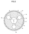
- Figure 2 is a sectional view taken along the II-II line of Figure 1;
- Figure 3 is a sectional view taken along the III-III line of Figure 1;
- Figure 4 is a sectional view taken along the IV-IV line of Figure 1;
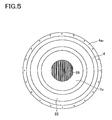
- Figure 5 is a sectional view taken along the line V-V of Figure 1; and
- Figure 6 is a sectional view of a revolving flow type combustion furnace in another embodiment of the present invention.
- [0058]
- 7
- Combustion chamber
- 8a
- Discharging opening
- 8b
- Introduction opening
- 20
- Atmospheric air introduction pipe
- Referring to Figures 1 to 5, the reference numeral 1 denotes a revolving flow type combustion furnace which burns, with a combustion flame of a revolving flow, a material to be burned which is charged.
- The revolving flow type combustion furnace 1 is provided with three column-shaped members, that is, an upper member 2, a middle member 3 and a
lower member 4. Each of themembers 2, 3, 4 is provided withframe bodies - A flange 2a1 is provided in a bottom end portion of the
frame body 2a. Similarly, a flange 3a1 is provided both in a top end portion and a bottom end portion of theframe body 3a, and also a flange 4a1 is provided in a top end portion of theframe body 4a. With thelower member 4, the middle member 3 and the upper member 2 stacked in this order from below, the flanges 2a1, 3a1, 4a1 are fastened by use ofbolts 5 andnuts 6, whereby the members 2,3 4 become integrated and the revolving flow type combustion furnace 1 is constructed. - The revolving flow type combustion furnace 1 is provided with a
combustion chamber 7 which is formed as a roughly oval body, and thiscombustion chamber 7 is constituted by anupper portion 7a of combustion chamber, amiddle portion 7b of combustion chamber and alower portion 7c of combustion chamber, which are provided in the members 2,3 4. - The
combustion chamber 7 is symmetrical with respect to a central axis line in a vertical direction (hereinafter referred to as "a major axis"), H (with the exception of the portions of a charging opening T, adischarging opening 8a and an introduction opening 8b), and has a largest diameter in an axis line in a horizontal direction in a virtually middle portion of thecombustion chamber 7 in the major axis H direction (hereinafter referred to as "a minor axis"), L. That is, the position of this minor axis L is the portion of the largest diameter of thecombustion chamber 7. Thecombustion chamber 7 is formed to obtain a sectional shape which is a roughly oval shape or a roughly ovoid shape in such a manner that the ratio of the major axis H to the minor axis L (H:L) is 7:4 to 9:8, and more preferably, the ratio (H:L) is 5:4 to 3:2. - According to an experiment by the present inventors, when the ratio (H:L) is such that the ratio of the minor axis L becomes larger than 9:8, for example, when the ratio (H:L) becomes 9:8.5, the shape resembles a sphere, and therefore, it becomes impossible to ensure the desired combustion volume within the
combustion chamber 7. In addition, the revolving flow of the combustion flame diffuses and it becomes impossible to increase the combustion route length. For this reason, the combustion efficiency decreases and if a larger volume of atmospheric air is introduced into thecombustion chamber 7 in order to raise the combustion efficiency, the moving speed of the combustion flame increases more and more, thereby causing the problem that combustible gases were discharged from a dischargingopening 8a before combustion. - Furthermore, according to an experiment by the present inventors, when the ratio (H:L) becomes less than 7:4, for example, when the ratio (H:L) becomes 8:4, the shape becomes too vertically long, and therefore, the heat radiation when a top portion of the interior of the
combustion chamber 7 is in a high temperature condition does not work well and a temperature drop in the top portion of the interior of thecombustion chamber 7 tends to become remarkable, with the result that the combustion efficiency decreased. - Consequently, by forming the
combustion chamber 7 as a roughly oval body in such a manner that the ratio (H:L) of the major axis H to the minor axis L of thecombustion chamber 7 is 7:4 to 9:8 as in the embodiment of the present invention, it is possible to satisfactorily obtain both effects, i.e., the effect of the combustion route length and the effect of heat radiation in a well-balanced manner and the combustion efficiency could be raised. In this embodiment shown in Figure 1, a roughly oval body having a ratio of the major axis H to the minor axis L of the combustion chamber 7 (H:L) of 5:4 is used. - The revolving flow type combustion furnace 1 is provided with a charging opening T for charging materials to be burned, such as residues occurring after the melting or decomposition treatment of shredder dusts coming from waste automobiles and the like, from the outside, a discharging
opening 8a which discharges gasses generated by the combustion of these materials to be burned, and anintroduction opening 8b which introduces exhaust gases discharged from the dischargingopening 8a and the like into thecombustion chamber 7. - The charging opening T is inclined downward so that combustible materials can be charged to the virtually middle portion of the interior of the
combustion chamber 7 in the major axis H direction. Incidentally, the charging opening T is provided in a position in the range of about 2/5 to 3/4 of the effective height within thecombustion chamber 7 in the major axis H direction of thecombustion chamber 7. Also in this case, the charging opening T is provided, the charging opening being directed toward the center of the major axis H direction of thecombustion chamber 7. - A charging pipe 10 for charging materials to be burned from a hopper 9 installed outside the revolving flow type combustion furnace 1 is inserted into this charging opening T. An upstream end of this charging pipe 10 and a downstream end of a
conveyor pipe 9a which extends horizontally outward from a side wall of a lower portion of the hopper 9 are connected by a vertical connection pipe 11. - A
top cover 9b is provided in an upper portion of the hopper 9, and materials to be burned are charged into the hopper 9 by opening thistop cover 9b. - On the upstream side of the charging pipe 10, there is provided a push-out
bar 12, which is constituted by abar portion 12a extending in the pipe direction of the charging pipe 10 and a push-outportion 12b having a shape which fits the shape of the inner circumference of the charging pipe 10. Thebar portion 12b of the push-outbar 12 is inserted into ahole 10b which is formed in the middle of aside wall 10a of an upstream end portion of the charging pipe 10. As a result, by pushing thebar portion 12b toward the downstream side of the charging pipe 10, it is possible to push a material to be burned which remains within the charging pipe 10 into thecombustion chamber 7. - In the lower portion of the hopper 9 and within the connection pipe 11, there is provided a
screw conveyor 13 which moves materials to be burned within the hopper 9 toward the downstream side of the connection pipe 11 and carries the materials to the charging pipe 10. Thisscrew conveyor 13 is driven by transmitting the power of amotor 14 installed on the upper side of the connection pipe 11 by use of abelt 15. Also, the power of thismotor 14 is transmitted to aloosening mechanism 17 provided within the hopper 9 via thescrew conveyor 13 and thebelt 16. - The
loosening mechanism 17 is constituted by arotary shaft 17a to which a rotary force is given by thebelt 6 and a plurality of looseningrods 17b attached perpendicularly to therotary shaft 17a. - Incidentally, it is preferred that this hopper 9 be constructed so as to be able to tilt at θ1 = approximately 5 degrees by use of predetermined tilting means.
- The discharging
opening 8a is provided in three places at equal intervals in theupper portion 7a of thecombustion chamber 7, and gases generated by the combustion within the combustion chamber are discharged from this dischargingopening 8a by natural convection. Theintroduction opening 8b is provided in three places at equal intervals on a wall surface which is lower than the middle of the height direction of themiddle portion 7b of the combustion chamber. The dischargingopening 8a and theintroduction opening 8b are in communication with each other by means of a sub-combustion-chamber section 18 and an air feed pipe 19 (a circulation device), and exhaust gasses from the dischargingopening 8a are again introduced into the introduction opening 8b through the sub-combustion-chamber section 18 and theair feed pipe 19. - An atmospheric
air introduction pipe 20 which introduces the atmospheric air from the outside is connected to a halfway portion of theair feed pipe 19. The downstream side of a portion of theair feed pipe 19 where the atmosphericair introduction pipe 20 is connected constitutes agas mixing portion 19a which mixes exhaust gasses from the dischargingopening 8a and the atmospheric air from the atmosphericair introduction pipe 20 together. - The
gas mixing portion 19a of theair feed pipe 19 is connected in a pipe direction which is inclined downward at θ2 = 5 degrees from the horizontal with respect to the introduction opening 8b of thecombustion chamber 7. As a result, it becomes easy to blow exhaust gases and the like against a material to be burned which is charged into thecombustion chamber 7 and positioned in thelower portion 7c of the combustion chamber. Furthermore, because the frequency of revolution of the revolving flow occurring in the portion lower than the introduction opening 8b increases, the mixing route of the atmospheric air and exhaust gases and the combustion route of these mixed gases become long and hence the combustion efficiency increases remarkably. - The
gas mixing portion 19a of theair feed pipe 19 is connected by being inclined at θ3 = 75 degrees in the horizontal direction with respect to a normal line direction a of a wall surface of the combustion chamber 7 (inclined at 15 degrees in the horizontal direction with respect to a tangential line direction b of a wall surface of the combustion chamber 7). As a result, the mixed gases of exhaust gases and the atmospheric gas are introduced from the introduction opening 8b along the inner wall of thecombustion chamber 7, and owing to these mixed gases which are introduced, it is possible to efficiently generate revolving flows within thecombustion chamber 7. - Atmospheric air pressurization means (not shown), such as a blower, is connected to an end portion of the atmospheric
air introduction pipe 20. The pressure for introducing atmospheric air into thecombustion chamber 7 by this atmospheric air pressurization means is 5 kgf/cm2 to 7 kgf/cm2 (0.5 MPa) and the volume of introduced atmospheric air is 600 Nmm3/h to 700 Nmm3/h. - The sub-combustion-
chamber section 18 is constituted by three sub-combustion-chambers 18a, 18b, 18c, which are respectively, a first sub-combustion-chamber 18a, a second sub-combustion-chamber 18b, and a third sub-combustion-chamber 18c. Each of the sub-combustion-chambers 18a, 18b, 18c is formed in such a manner that the shape of the interior of the chamber is a roughly spherical body, and the radius of the spherical body of the first sub-combustion-chamber 18a is larger than the diameter of the dischargingopening 8a. The radius of a spherical body decreases in order of the first sub-combustion-chamber 18a, the second sub-combustion-chamber 18b, and the third sub-combustion-chamber 18c. - As a result, the flow velocity of exhaust gasses discharged from the discharging
opening 8a is reduced when the exhaust gasses enter the first sub-combustion-chamber 18a, and the residence time of the exhaust gasses in the first sub-combustion-chamber 18a becomes long. And the exhaust gasses the combustion of which has further proceeded during the residence in first sub-combustion-chamber 18a enter the second sub-combustion-chamber 18b and the third sub-combustion-chamber 18c in this order, and the flow velocity is increased upon entrance. Because in this manner, the radius of each spherical body decreases gradually in order of the first sub-combustion-chamber 18a, the second sub-combustion-chamber 18b, and the third sub-combustion-chamber 18c, it is ensured that the velocity of exhaust gases upon passage does not change abruptly. - A
discharge pipe 21 which extends downward is connected to a halfway portion of the above-mentionedair feed pipe 19, and acirculation section 23 is connected to a bottom end of thisdischarge pipe 21 via aconnection section 22. Theconnection section 22 and thecirculation section 23 are formed laterally from thelower portion 7c of the combustion chamber along the full circumference. Anexternal exhaust pipe 24 which is in communication with the outside is connected to thecirculation section 23, and atmospheric air suction means (not shown) is connected to thisexternal exhaust pipe 24. - The volume of the atmospheric air sucked by this atmospheric air suction means is set so that it exceeds the volume of the atmospheric air introduced by the above-mentioned atmospheric air introduction means, with the result that the interior of the
combustion chamber 7 is kept at a negative pressure of approximately -1 mmAq to -5 mmAq. This pressure within thecombustion chamber 7 of -1 mmAq to -5 mmAq is such that the combustion flame does not flow back from the charging opening T and the discharge speed of combustible gasses and combustion flame generated from a material to be burned to the dischargingopening 8a does not become too high, either. - An
ash discharging passage 25 is in communication with the lower side of the bottom of thelower portion 7c of the combustion chamber, and asieve 26 capable of being vibrated from the outside is installed in this bottom of thelower portion 7c. Thissieve 26 is provided with two-stage upper and lower meshes, the upper mesh being formed coarsely and the lower mesh being formed finely. By vibrating thissieve 26 from the outside, fine ash after combustion is caused to fall onto theash discharging passage 25, and this ash is discharged to the outside by predetermined discharging means. - Next, the operation of this embodiment will be described.
- First, a material to be burned is charged into the hopper 9. And when the
motor 14 is driven, the material to be burned in the hopper 9 is loosened by theloosening mechanism 17 and the material to be burned which has been loosened and has fallen onto the lower portion of the hopper 9 is carried by thescrew conveyor 13 to the downstream side of theconveyor pipe 9a. The material to be burned which has been carried to the downstream side of theconveyor pipe 9a falls into the charging pipe 10 via the connection pipe 11 and is charged by the inclination of the charging pipe 10 from the charging opening T into thecombustion chamber 7. This material to be burned is a residue which is obtained by drying a sludge-like substance and removing liquid portions therefrom. This sludge-like substance is such that it remains without being melted or decomposed after the melting or decomposition of crushed shredder dusts of portions of a waste automobile containing large amounts of resins, which are represented by an instrumental panel and a sheet, by use of a solvent and steam. This residue is in a solid and powdery state and contains metals, earth and sand, glasses and carbons in addition to undecomposed resins. - Next, by charging a kindling material (a sheet of burning newspaper and the like) from the charging opening T, the material to be burned in the
combustion chamber 7 is ignited. And by driving the above-mentioned atmospheric air pressurization means, the atmospheric air is supplied from the atmosphericair introduction pipe 20 to theintroduction opening 8b. As a result, the atmospheric air is introduced from the introduction opening 8b in three places along the inner wall of thecombustion chamber 7 and a revolving flow in a spiral form is generated in thecombustion chamber 7. And the combustion flame of the material to be burned comes to the revolving flow and revolves. - Gases generated by the combustion of the material to be burned in this revolving flow are discharged from the
discharge opening 8a and enter the sub-combustion-chamber section 18. Because the flow velocity of the gases which have entered the first sub-combustion-chamber 18a of the sub-combustion-chamber section 18 is reduced as described above, the residence time of the gasses in the first sub-combustion-chamber 18a becomes long and unburned gasses, soot and the like which are contained in the exhaust gasses are burned again. Furthermore, the re-combustion of unburned gases, soot and the like is performed while the flow velocity in the second sub-combustion-chamber 18b and the third sub-combustion-chamber 18c is being increased. And the re-burned exhaust gasses flow from the third sub-combustion-chamber 18c into theair feed pipe 19 and are mixed with the atmospheric air introduced from the atmosphericair introduction pipe 20 in thegas mixing portion 19a. This mixed gas is introduced from the introduction opening 8b into thecombustion chamber 7. - A part of exhaust gasses from the
air feed pipe 19 and a part of the atmospheric air from the atmosphericair introduction pipe 20 flow into thedischarge pipe 21, and these exhaust gasses circulate through thecirculation section 23 via theconnection section 22. Thelower member 4 is thermally insulated by the heat of exhaust gasses which circulate through thiscirculation section 23 and a temperature drop within thecombustion chamber 7 is prevented. In the initial stage of combustion, the temperature within thecombustion chamber 7 rises rapidly. - The exhaust gasses exhausted from the
external exhaust pipe 24 after the circulation through thecirculation section 23 pass through a catalyst, and the exhaust gasses, along with the combustion flame, are delivered to a secondary combustor (not shown). In this secondary combustor, unburned gasses (hc, carbon monoxide, etc.) which cannot be burned in the sub-combustion-chamber section 18 are burned at 800 to 900°C, and then, converted into CO2 and H2O. And the exhaust gasses passing through the secondary combustor are treated and converted into CO2 and H2O in an exhaust gas treatment system. - When in this state, a material to be burned is intermittently charged each time in a predetermined quantity from the charging opening T, the charged material to be burned is fed to the vicinity of the middle portion in the height direction of the
combustion chamber 7, reacts with the revolving flow in thecombustion chamber 7, and is burned. On this occasion, the temperature within thecombustion chamber 7 reaches high levels (1200 to 1350°C or more) owing to the combustion flame of the revolving flow. - When a residue was burned in the revolving flow combustion furnace 1 constructed as described above, the combustion condition was good, and a furnace temperature of 1350°C could be obtained in the middle portion of the
combustion chamber 7 where the temperature is highest. The soot generation rate was suppressed to 1% or less, the CO concentration was suppressed to 10 ppm or less, and the dioxin concentration was suppressed to 0.4 ng/m3 or less. - Incidentally, in this embodiment, the
gas mixing portion 19a of theair feed pipe 19 is connected in a pipe direction which is inclined downward at 5 degrees from the horizon, to the introduction opening 8b within thecombustion chamber 7. However, the present invention is not limited to this. Any inclination angle can be adopted so long as it increases the frequency of revolution of the revolving flow which is generated in a portion lower than the introduction opening 8b within thecombustion chamber 7, and so long as the inclination angle is such that the mixing route of the atmospheric air and exhaust gasses and the combustion route of these mixed gasses become long and the combustion efficiency increases remarkably. Specifically, the inclination angle is adjusted to an angle between 0 degree or more and 15 degrees or less according to the pressure and volume of the introduced atmospheric air. - In this embodiment, the
gas mixing portion 19a is inclined at 75 degrees in the horizontal direction with respect to a normal line direction of a wall surface of the combustion chamber 7 (inclined at 15 degrees in the horizontal direction with respect to a tangential line direction of a wall surface of the combustion chamber 7). However, the present invention is not limited to this. Any inclination angle can be adopted so long as it is such that the mixed gases are introduced from the introduction opening 8b along the inner wall of thecombustion chamber 7 and revolving flows are efficiently generated within thecombustion chamber 7. Specifically, thegas mixing portion 19a is inclined in the horizontal direction with respect to a normal line direction of a wall surface of the combustion chamber according to the pressure and volume of the introduced atmospheric air, the size and shape of the combustion chamber, etc. - Incidentally, in this embodiment, the
introduction opening 8b is provided in three places at equal intervals on a wall surface which is lower than the middle of the height direction of themiddle portion 7b of the combustion chamber. However, the present invention is not limited by this. For example, it is possible to provide the introduction opening 8b in two places, each place having a different position, in the height direction of thecombustion chamber 7 so that adifferent introduction opening 8b can be used depending on the quantity of a material to be burned which is charged into thecombustion chamber 7. - Although in this embodiment the description has been given of the roughly
oval combustion chamber 7, the present invention is not limited to this. For example, acombustion chamber 7 as shown in Figure 6 may be used. - In this
combustion chamber 7, an inner wall surface of anupper portion 7a of the combustion chamber is made a little flat so as to swell outward from a roughly oval shape, an area near the middle portion of the interior of thecombustion chamber 7 in the major axis H direction (an area near a maximum diameter of the combustion chamber 7) is formed as a planar surface which is virtually inscribed in the roughly oval shape, and alower portion 7c of the combustion chamber is also formed as a planar surface which is virtually inscribed in the roughly oval shape which is parallel to a minor axis L. - Incidentally, a planar surface which is virtually inscribed in the roughly oval shape is also formed between the area near the middle portion of the interior of the
combustion chamber 7 in the major axis H direction, (an area near a maximum diameter of the combustion chamber 7) and the inner wall surface of thelower portion 7c of the combustion chamber. Other points in construction are the same as in the embodiment shown in Figure 1, and overlapping descriptions are omitted. - Because in this embodiment the curved surface of the inner wall surface of the
upper portion 7a of thecombustion chamber 7 is made a little flat, the radiation heat from the combustion flame of revolving flow, which is a heat source, is efficiently reflected from the inner wall surface of theupper portion 7a, with the result that it is possible to further improve the combustion efficiency by further raising the heat radiation effect. - Furthermore, because the area near the middle portion (the area near a maximum diameter of the combustion chamber 7) is formed as a planar surface and the inner wall surface of the
lower portion 7c is also formed as a planar surface, it is possible to increase the area of contact with combustible gasses, as compared with the case of a curved surface. Therefore, the combustion efficiency can be further improved by raising the generation rate of combustible gasses. - Incidentally, also in this embodiment, the
combustion chamber 7 is formed to obtain a sectional shape in such a manner that the ratio of the major axis H to the minor axis L (H:L) is 7:4 to 9:8, and more preferably, the ratio (H:L) is 5:4 to 3:2.
Claims (4)
- A combustion chamber of a revolving flow type combustion furnace which burns and incinerates, with a combustion flame of a revolving flow, a material to be burned which is charged, characterized in that the combustion chamber is a roughly oval body which is constructed in such a manner that the combustion chamber is longer in a vertical direction than in a horizontal direction and that a virtually middle portion of the combustion chamber in the vertical direction thereof is bulged in the horizontal direction so that a horizontal surface of the virtually middle portion obtains a maximum diameter and the ratio of a major axis in the vertical direction to a minor axis in the virtually middle portion which is orthogonal to the major axis in the vertical direction is 7:4 to 9:8.
- The combustion chamber of a revolving flow type combustion furnace according to claim 1, characterized in that a charging opening for charging a material to be burned into the combustion chamber is provided in the range of 2/5 to 3/4 of an effective height in the vertical direction within the combustion chamber, the charging opening being directed toward the virtually middle portion where a maximum diameter is obtained.
- The combustion chamber of a revolving flow type combustion furnace according to claim 1, characterized in that the virtually middle portion of the combustion chamber of the roughly oval body where a maximum diameter is obtained has a planar shape.
- The combustion chamber of a revolving flow type combustion furnace according to claim 1, characterized in that a lowermost portion of the roughly oval body has a planar shape.
Applications Claiming Priority (3)
| Application Number | Priority Date | Filing Date | Title |
|---|---|---|---|
| JP2003324518 | 2003-09-17 | ||
| JP2004270224A JP4119410B2 (en) | 2003-09-17 | 2004-09-16 | Swirl type combustion furnace |
| PCT/JP2004/013662 WO2005028958A1 (en) | 2003-09-17 | 2004-09-17 | Combustion chamber for revolving flow type combustion furnace |
Publications (2)
| Publication Number | Publication Date |
|---|---|
| EP1679473A1 true EP1679473A1 (en) | 2006-07-12 |
| EP1679473A4 EP1679473A4 (en) | 2011-08-24 |
Family
ID=34380306
Family Applications (1)
| Application Number | Title | Priority Date | Filing Date |
|---|---|---|---|
| EP04787906A Withdrawn EP1679473A4 (en) | 2003-09-17 | 2004-09-17 | Combustion chamber for revolving flow type combustion furnace |
Country Status (3)
| Country | Link |
|---|---|
| EP (1) | EP1679473A4 (en) |
| JP (1) | JP4119410B2 (en) |
| WO (1) | WO2005028958A1 (en) |
Cited By (1)
| Publication number | Priority date | Publication date | Assignee | Title |
|---|---|---|---|---|
| CN106482111A (en) * | 2016-12-16 | 2017-03-08 | 郑佳丹 | A kind of solid waste treatment facility and its processing method |
Family Cites Families (4)
| Publication number | Priority date | Publication date | Assignee | Title |
|---|---|---|---|---|
| GB1506760A (en) * | 1976-10-04 | 1978-04-12 | Cea Combustion Ltd | Incinerator |
| US5203267A (en) * | 1991-01-22 | 1993-04-20 | New Clear Energy, Inc. | Method and apparatus for disposing of waste material |
| US5558028A (en) * | 1995-07-11 | 1996-09-24 | Lin; Wen-Chiang H. | Incinerator frame |
| JP2003065510A (en) * | 2001-08-23 | 2003-03-05 | Kurimoto Ltd | Swirl type melting furnace |
-
2004
- 2004-09-16 JP JP2004270224A patent/JP4119410B2/en not_active Expired - Fee Related
- 2004-09-17 EP EP04787906A patent/EP1679473A4/en not_active Withdrawn
- 2004-09-17 WO PCT/JP2004/013662 patent/WO2005028958A1/en not_active Ceased
Cited By (1)
| Publication number | Priority date | Publication date | Assignee | Title |
|---|---|---|---|---|
| CN106482111A (en) * | 2016-12-16 | 2017-03-08 | 郑佳丹 | A kind of solid waste treatment facility and its processing method |
Also Published As
| Publication number | Publication date |
|---|---|
| JP4119410B2 (en) | 2008-07-16 |
| JP2005121356A (en) | 2005-05-12 |
| WO2005028958A1 (en) | 2005-03-31 |
| EP1679473A4 (en) | 2011-08-24 |
Similar Documents
| Publication | Publication Date | Title |
|---|---|---|
| EP0426471B1 (en) | Municipal waste thermal oxidation system | |
| US4708067A (en) | Method of catalystless denitrification for fluidized bed incinerators | |
| JP4889176B2 (en) | Method and apparatus for burning solid fuel, especially solid waste | |
| EP0555501B1 (en) | Dry distillation type incinerator | |
| JP2004093113A (en) | Improved large quantity fuel combustion system | |
| US4934931A (en) | Cyclonic combustion device with sorbent injection | |
| EP0237720B1 (en) | Method of secondary combustion promotion for a fluidized bed incinerator | |
| JPH10253029A (en) | Incinerator | |
| US4753180A (en) | Method of stable combustion for a fluidized bed incinerator | |
| EP1679473A1 (en) | Combustion chamber for revolving flow type combustion furnace | |
| JP2972081B2 (en) | Incinerator | |
| US3882798A (en) | Secondary bed elutriation arrestor for a fluid bed disposal method and apparatus | |
| CN214501241U (en) | Refuse incinerator | |
| JP2003074817A (en) | Waste gasification and melting equipment and its operation method | |
| RU2229060C2 (en) | Oil-slime heat treatment installation | |
| JP4078342B2 (en) | Swirl furnace | |
| JPH08226623A (en) | Incinerating device for polymeric waste | |
| JP2006200768A (en) | Incinerator | |
| US6619218B2 (en) | Method and apparatus for making a pollutant harmless | |
| JP2001012714A (en) | Re-combustion furnace and recombustion equipment | |
| JPH1111607A (en) | Chute for throwing industrial waste into disposal furnace | |
| JP3172751B2 (en) | Fluidized bed combustion method | |
| RU38381U1 (en) | DEVICE FOR OXIDATION OF METAL WASTE | |
| JP4378528B2 (en) | Fluidized bed furnace and its incineration method. | |
| JPH06193845A (en) | Charging device for matter to be incinerated and incinerator using same |
Legal Events
| Date | Code | Title | Description |
|---|---|---|---|
| PUAI | Public reference made under article 153(3) epc to a published international application that has entered the european phase |
Free format text: ORIGINAL CODE: 0009012 |
|
| 17P | Request for examination filed |
Effective date: 20060412 |
|
| AK | Designated contracting states |
Kind code of ref document: A1 Designated state(s): DE GB |
|
| DAX | Request for extension of the european patent (deleted) | ||
| RBV | Designated contracting states (corrected) |
Designated state(s): DE GB |
|
| RIN1 | Information on inventor provided before grant (corrected) |
Inventor name: UEMURA, TAKAYUKI,C/O PACIFIC METALS CO., LTD. Inventor name: TAJIMA, NORIOC/O HONDA ENGINEERING CO., LTD. Inventor name: SOGA, YOSHISADA,C/O PACIFIC METALS CO., LTD. Inventor name: KUWABARA, MITSUO,C/O HONDA ENGINEERING CO., LTD. Inventor name: YAEZAWA, HIDEAKI,C/O PACIFIC METALS CO., LTD. Inventor name: WATANABE, MITSUOC/O HONDA ENGINEERING CO., LTD. Inventor name: SATOU, AKIRA,C/O PACIFIC METALS CO., LTD. |
|
| RAP1 | Party data changed (applicant data changed or rights of an application transferred) |
Owner name: HONDA MOTOR CO., LTD. |
|
| A4 | Supplementary search report drawn up and despatched |
Effective date: 20110726 |
|
| RIC1 | Information provided on ipc code assigned before grant |
Ipc: F23G 5/32 20060101AFI20110720BHEP |
|
| 17Q | First examination report despatched |
Effective date: 20120503 |
|
| 17Q | First examination report despatched |
Effective date: 20120514 |
|
| STAA | Information on the status of an ep patent application or granted ep patent |
Free format text: STATUS: THE APPLICATION IS DEEMED TO BE WITHDRAWN |
|
| 18D | Application deemed to be withdrawn |
Effective date: 20120925 |